Red Baron Sit-Down DP-171-1st-01B
Red Baron (revised hardware) (Atari, 1980) · Drawing Package · 1 pages · original scan
i ee J2 33 iii eeu. 2 eyes
5983 FIH2 ¢ Figure 1
AUXILIARY PCB pre reeeer 8888 8888 eee
Se 2] (DSK, ¢ a
[000000000000
Figure 2A Figure 2B
PORTION OF AUXILIARY PCB PORTION OF AUXILIARY PCB
C1
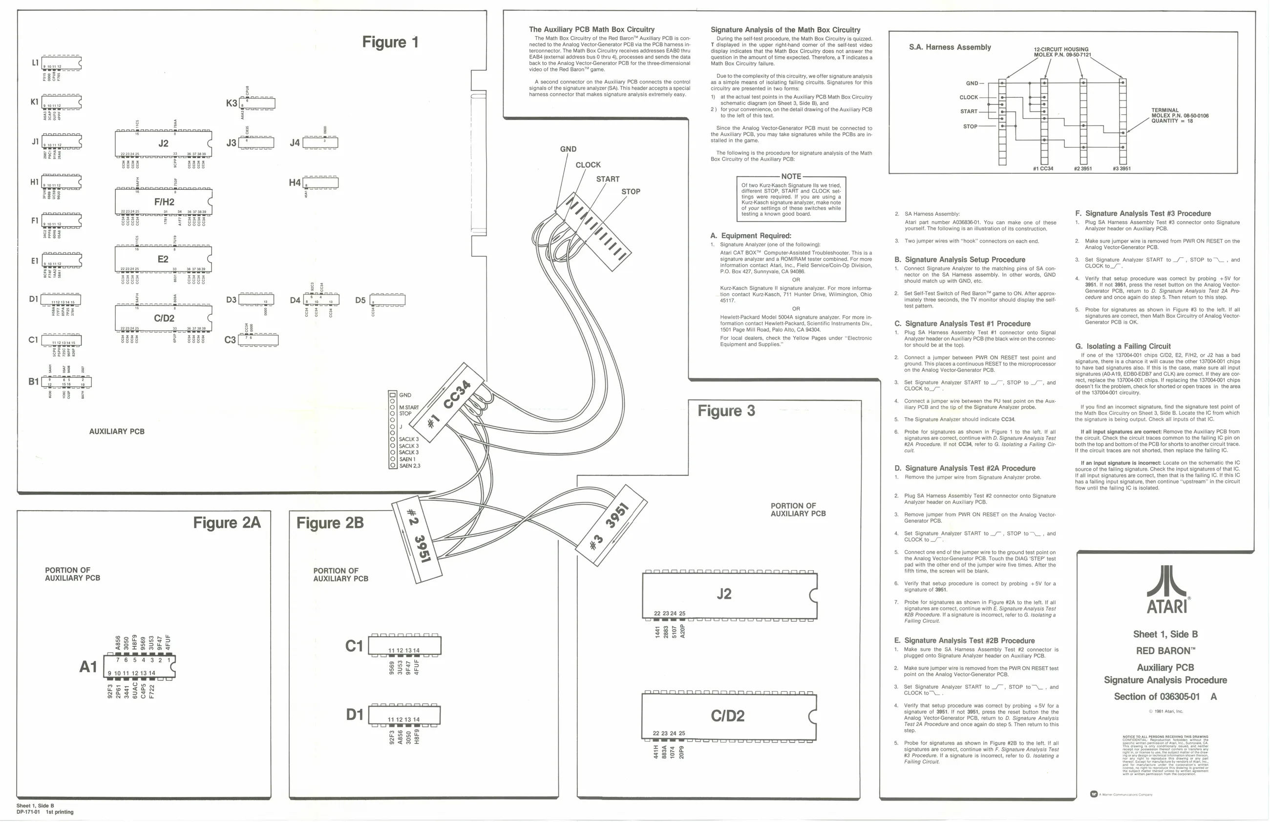
a Sheet 1, Side B DP-171.01 1st printing 9565 The Auxiliary PCB Math Box Circuitry ‘The Math Box Circuitry of the Red Baron™ Auxiliary PCB is connected to the Analog Vector-Generator PCE via the PCB harness in terconnector. The Math Box Circuitry receives addresses EABO thru EAB¢ (external address bus 0 thru 4), processes and sends the data back to the Analog Vector Generator PCB for the three-dimensional video of the Red Baron™ game,
‘A second connector on the Auxiliary PCB connects the contro signals of the signature analyzer (SA). This header accepts a special harness connector that makes signature analysis extremely easy.
GND
Figure 3 Signature Analysis of the Math Box Circuitry During the sel-test procedure, the Math Box Circultry is quizzed. T displayed in the upper righthand comer of the selttest video display indicates that the Math Box Circultry does not answer the question in the amount of time expected. Therefore, a T indicates a Math Box Circuitry failure. Due to the complexity ofthis circuitry, we offer signature analysis as a simple means of isolating falling circuits. Signatures for this Circuitry are presented in two forms:
- at the actual test points in the Auxiliary PCB Math Box Circuitry schematic diagram (on Sheet 3, Side B), and
- foryour convenience, on the detail drawing of the Auxiliary PCB to the left ofthis text
Since the Analog VectorGenerator PCB must be connected to the Auxiliary PCB, you may take signatures while the PCBs are installed in the game,
‘The following is the procedure for signature analysis of the Math Box Circuitry of the Auxiliary PCB:
A. Equipment Required:
- Signature Analyzer (one of the following ‘ari CAT BOX™ Computer Assisted Troubleshooter. This isa signature analyzer and a ROMIRAM tester combined, For more information contact Atari, Inc. Field ServicelCoin Op Division, P.O, Box 427, Sunnyvale, CA 94088, on Kureasch Signature I! signature analyzer. For more informa: tion contact KureKaseh, 711 Hunter Oxve, Wilmington, Ohio 4517 on Hewlett Packard Model 50044 signature analyzer. For more Information contact Hewlet Packard, Scientific Inetruments Div 1601 Page Mill Road, Palo Alto, CA 94308, For local dealers, check the Yellow Pages under “Electronic Equipment an Supplies.”
PORTION OF AUXILIARY PCB S.A. Harness Assembly MOLEX 42.IRCUIT HOUSING 08-50-7121 i A] ono— fo}
Lock.
START,
stop: BCI LILILI TERMINAL, MOLEX P.N. 06-50-0106 QUANTITY = 18
#23951 3.9951
SA Hamess Assembly: ‘Atari part number A036896.01. You can make one of these yourself. The following is an illustration of its construction,
‘Two jumper wires with “hook” connectors on each end.
Signature Analysis Setup Procedure Connect Signature Analyzer to the matching pins of SA connector on the SA Hamess assembly. In other words, GND should match up with GND, ete
Set Self-Test Switch of Red Baron™ game to ON. After approximately three seconds, the TV monitor should display the selt test pattern.
Signature Analysis Test #1 Procedure Plug SA Hamess Assembly Test #1 connector onto Signal ‘Analyzer header on Auxiliary PCB (the black wire on the connec tor should be at the top)
Connect a jumper between PWR ON RESET test point and (round. This places a continuous RESET to the microprocessor fon the Analog Vector-Generator PCB.
Set Signature Analyzer START to _/—, STOP to _/~, and CLOCK to_~
Connect a jumper wire between the PU test point on the Aux: llary PCB and the tip of the Signature Analyzer probe.
The Signature Analyzer should indicate CCA.
Probe for signatures as shown in Figure 1 to the left. If all signatures are correct, continue with D. Signature Analysis Test #24 Procedure. f not CC34, refer to G. Isolating a Failing Circuit
‘Signature Analysis Test #2A Procedure Remove the jumper wire from Signature Analyzer probe.
Plug SA Harness Assembly Test #2 connector onto Signature ‘Analyzer header on Auxiliary PCB.
Romove jumper from PWR ON RESET on the Analog Vector: Generator PCB,
Set Signature Analyzer START to_/, STOP to™\_, and CLOCK to_/— Connect one end of the jumper wire to the ground test point on, the Analog Vector-Generator PCB. Touch the DIAG ‘STEP’ test, ‘pad with the other end of the jumper wire five times. After the fifth time, the screen will be blank.
Verity that setup procedure is correct by probing +5V for a signature of 3951.
robe for signatures as shown in Figure #2A to the left. If all signatures are correct, continue with E. Signature Analysis Test #28 Procedure. Ifa signature is incorrect, refer to G. Isolating @ Failing Circuit
‘Signature Analysis Test #2B Procedure Make sure the SA Hamess Assembly Test #2 connector is plugged onto Signature Analyzer header on Auxiliary PCB.
Make sure jumper wire is removed from the PWR ON RESET test ppoint on the Analog Vector-Generator PCB,
Set Signature Analyzer START to_/—, STOP to—\_, and CLOCK to
Verity that setup procedure was correct by probing +5V for a signature of 3951. If not 3951, press the reset button the the ‘Analog Vector-Generator PCB, retun to D. Signature Analysis Test 2A Procedure and once again do step 5. Then return to this step.
Probe for signatures as shown in Figure #28 to the left. If all signatures are corect, continue with F. Signature Analysis Test 43 Procedure. It signature is incorrect, refer to G. Isolating @ Falling Circuit. F. Signature Analysis Test #3 Procedure
- Plug SA Hamess Assembly Test #3 connector onto Signature ‘Analyzer header on Auxiliary PCB.
2, Make sure jumper wire is removed from PWR ON RESET on the Analog Vector-Generator PCB.
- Set Signature Analyzer START to _/~, STOP to-\_, and CLOCK to_/—.
- Verity that setup procedure was correct by probing +5V for 951. If not 3951, press the reset button on the Analog Vector- Generator PCB, return to D. Signature Analysis Test 2A Pro- Cedure and once again do step 5. Then return to this step.
- Probe for signatures as shown in Figure #3 to the left. If all signatures are correct, then Math Box Circuitry of Analog Vector. Generator PCB is OK.
G. Isolating a Failing Circuit If one of the 137004001 chips CID2, £2, FIM2, or J2 has a bad signature, there is a chance it will cause the other 137004.001 chips to have bad signatures also. If this is the case, make sure all input signatures (AO-A19, EDB0-EDB7 and CLK) are correct. If they are cor: rect, replace the 137004001 chips. If replacing the 137004-001 chips doesn't fix the problem, check for shorted or open traces in the area
If you find an incorrect signature, find the signature test point of the Math Box Circuitry on Sheet 3, Side B. Locate the IC from which the signature is being output. Check all inputs of that IC. {Hall input signatures are correct: Remove the Auxillary PCB from the circuit. Check the circuit traces common to the falling IC pin on ‘both the top and bottom of the PCB for shorts to another circuit trace. Ifthe circuit traces are not shorted, then replace the falling IC.
It an input signature is incorrect: Locate on the schematic the IC ‘source ofthe falling signature. Check the input signatures of that IC. it all input signatures are correct, then that is the failing IC. If this IC has a failing input signature, then continue “upstream in the circult flow until the failing IC is isolated.
A ATARI
Sheet 1, Side B
RED BARON™
Auxiliary PCB Signature Analysis Procedure
Section of 036305-01 A