Xevious TM-230 1st Printing
Xevious (Namco) (Namco, 1982) · Technical Manual · 72 pages · 46 sections · original scan
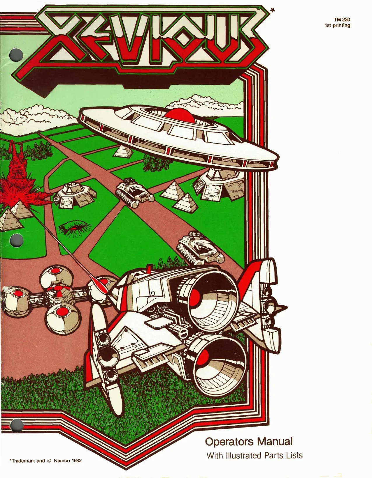
This page is a drawing, shown as the original scan.
If reading through this manual does not lead to solving a certain maintenance problem, call TELEHELP® at the Atari Customer Service office in your geographical area, as shown below.
WEST and CENTRAL U.S.A. Parts and Service
Atari, Inc. California Customer Service Office 1105 N. Fair Oaks Avenue P. O. Box 427, Sunnyvale, CA 94086 Telex 17-1103 (Monday-Friday, 7:30-4:00 pm Pacific Time) = From California, Alaska, or Hawaii (408) 745-2900 OW Service from anywhere in the area shown in white toll-free (800) 538-1611
EAST U.S.A. Service only
Atari, Inc. New Jersey Customer Service Office 12A World's Fair Drive, Somerset, Nj 08873 Telex 37-9347 (Monday-Friday, 7:30-4:00 pm Eastern time) zs From New Jersey (201) 469-5993 = From anywhere else in this area toll-free (800) 526-3849
EUROPE Parts and Service
Atari Ireland Limited European Customer Service Office Tipperary Town, Ireland Telex 28-165 TIPPERARY TOWN, (Monday-Friday, 9:00-6:00 pm GMT) IRELAND.
BH 0062-52155
Operators Manual
With Hlustrated Parts Lists
Xevious
© 1983 by Atari, Inc. All rights reserved. No part of this publication may be reproduced by any mechanical, photographic, or electronic process, or in the form of a phonographic recording, nor may it be stored in a retrieval system, transmitted, or otherwise copied for public or private use, without permission from the publisher. The game play, all graphic designs, this technical manual, its accompanying schematic diagrams, and the display manual are protected by the U.S. Copyright Act of 1976. This Act provides for increased penalties for violating federal copyright laws. Courts can impound infringing articles while legal action is pending. If infringers are convicted, courts can order destruction of the infringing articles. In addition, the Act provides for payment of statutory damages of up to $50,000 in certain cases. Infringets may also have to pay costs and attorneys’ fees, fines up to $25,000, and face an imprisonment Of up to one year. Atari will aggressively enforce its copyrights against any infringers. We will use all legal means to immediately halt any manufacture, distribution, or operation of a copy of video games made by us. Anyone who purchases such copies risks forfeiting such a game.
Published by: ATARI, INC 790 Sycamore Drive P.O. Box 906 Milpitas, California 95035
Lithographed in the U.S.A. IM
Xerious
Notice Regarding Non-ATARI Parts
Use of non-ATARi parts or modifications of your ATARI game circuitry may adversely affect the safety of your game, and injure you or your pk:
You may void the game warranty (printed on the inside back cover of this manual) if you do any of the following:
@ substitute non-ATARI parts in the game ® modify or alter any circuits in the gaine by using kits or parts vot supplied by Atari.
tii
Nevious
Table of Contents
1 Set-Up Procedures How to Use This Manual... 0.2.0.6... Game Overview .. we Installation Specifications . inspecting the Game . Voltage-Plug ction and Fuses . . Switch Locations... ... - Power On/Off Switch Utility Panel Switches. Option Switches G. Selecting the Options. =m OOR>
- Self-Test Procedure A. Obtaining a Self-Test Display B. Checking Controls and Sounds . . Cc. Checking Option Settings . D. Checking Display Convergence
- Illustrated Parts Lists A. Cabinet Mounted Assemblies... 0.0.6... . Control Panel Assemblies oe ee Cc. Upper Fluorescem Tube and Speaker Assemblit D. Video Display and Lower Fluorescent Tube Assemblies E. Utility Panel Assembly . . . F, Coin Door Assemblies Fee G. Printed-Circuit Boards... 6.0... H. Power Supply Assembly .......
iv py ra
THAR NS
Figure 1-1 Figure 1-2 Figure 1-3 Figure 2-1 Figure 2-2 Figure 2-3 Figure Figure 3 Figure
Figure 3-6 Figure 3-7 Figure 3-8 Figure 3-9 Figure 3-10
Figure 3-1 Figure 3-12 Figure 3-13
Figure 3-14 Figure 3-15 Figure 3-16
Table 1-1 Table 1-2 Table 1-3 Table 2-1 Table 2-2 Table 2-3 Xevious
List of Illustrations
Game Overview .... . fom we sie Voltage-Selection Plug and Fuse Locat ALIONS . oye eeee Option Switch Locations .. 2.6... Self-Test Display (RAM and ROM Operating Properly) Self-Test Display (RAM Failure) Begs) aegely Self-Test Display (ROM) Failure) eee ena hatch Pattern Display ........... Cabinet-Mounted Assemblies, U.S.-Built Cabinet-Mounted Assemblies, Ireland-Built Control Panel Assembly 0 Position Joystick Assembly. : Upper Fluorescent Tube and Speaker Assemblies wee Video Display and Lower Fluorescent Tube Assemblies... .. . . Utility Panel Assembly... .. Vertically Mounted Coin Door American-Made Coin Door... 2,2... - see beeen teens Electromagnetic Interference (EMI) Cage Assembly and PCB Mounting Hardware .... 22... Fee eee EMI Shield try Assembly . . . . seb et eee Assembly (ATARI) Dee nase nme esta ee Xevious a PCB Assembly (ATARI)... 2000000000220
Xevious CPU PCB Assembly Parts List(Namco). 2... Xevious Video PCB Assembly Parts List (Namco) a Regulator/Audio Il PCB Assembly, U.S.-Built. 2... 00.000. : Regulator/Audio II PCB Assembly, Ireland-Built. .. 2.2.0... Power Supply Assembly
Installation Specifications... ....0.......- Switch Settings for Price and Bonus Options Switch Settings for Price and Difficulty Options RAM Locations . . . . beavis feeb emery eee ROM Locations ..... 2... . Xevious Sounds 6...
Xevtous
oF
This equipment generates, uses, and can radiate radio frequency energy and if not installed and used in accordance with the instruction manual, may cause interference to radio communications. [thas been tested and found to comply with the limits for a Class A comput ing device pursuant to Subpart] of Part 15 of Federal Communications Commission (FCC) Rules, which are designed to provide reasonable protection against such interference when operated ina commercial environment. Operation of this equipment in a residential area or Modification to this equipment is hkely to cause interference in which case the user, at his own expense, will be required to ake whatever measures may be required to correct the interference. If you suspect interference from an ATARI® game at your location, check the following: e All green ground wires in the game are properly connected as shown in the game wiring diagram
© = The power cord is properly phigged into a grounded three-wire outlet
e The game printed-circuit board(s) (PCB) is properly installed within the Electromagnetic Interference (EMD cage. © = The EMI Shield PCB is properly installed and connected in series with the game PCB. harness: All filter capacitors required on the EMI Shield PCB are properly soldered in place. If you are still unable to solve the interference problem, please contact ATARI Customer Service. See the inside front cover of this manual for service in your area.
Set-Up Procedures
A. How to Use This Manual
This manual, written for game operators and service technicians, describes the Xevious game. The manual contains information about both the Ireland- and U.S.-built games. Whenever information is unique to the
Ireland-built game, this symbol appears: *
Whenever information is unique to the U.S.-built game, this symbol appears:
Chapter | contains game specifications, inspection procedures, voltage plug and fuse information, switch locations, and option information. Chapter 2 contains self-test procedures. Chapter 3 contains illustrated parts lists. Figures 3-1 and 3-2 illustrate the U.S-built and the treland-built game cabinets, Italicized type on these figures refer you to other places in the manual for more information about specific cabinet parts. schematic diagrams of the game circuitry are included as a supplement to this manual.
Chapter
Ser-Up Procedures
Upper Fluorescent Tube & Speaker See Figure 3-5
Video Display *
a See Figure 3-6
Lower Fluorescent Tube & Attraction Panel See Figure 3-6
Control Panel See Figure 33
Coin Door See Figures 38 & 3-9
Utility Panel See Figure 3-7
x item with 4 serial number label (U.S.-built cabinet) Nevious
Game Identification Label « (Serial number appears here on Ireland-built games)
Access panel
EMI Cage See Figure 3-10
Joystick Assy.
See Figure 34 EMI Shield PCB
See Figure 3-11
Video PCB x See Fig. 3-3 for Atari PCB Nameo PCB not illustrated
CPU PCB* See Fig. 3-12 for Atari PCB Namco PCB not illustrated
Power Supply *« See Figure 3-16
Regulator! Audio Ii PCB x See Figures 3-14 & 3-15 Power On/Off Switch 90"
Shock Hazard
Do not plug in the game until it has been inspected. This game should only be connected to a grounded 3wire outlet. If you have only a 2-wire outlet, we recommend you hire a licensed electrician to instatl a grounded outlet. Players may receive an electrical shock if this game is Not properly grounded!
Figure 1-1 Game Overview
Xevious
B. Game Overview
The game Xevious carries you as the Solvalou spacecraft pilot. You will fly through a host of flying enemies and land-based obstacles that try to shoot you from the sky. Your mission is to reclaim the enemyoccupied Earth by shooting and bombing the enem: to oblivion. You must skillfully pilot your spacecraft through harder and harder encounters with the enemy. A new feature for this game is an additional attraction panel located below the video display. This lower attraction panel enhances the visual appeal of the cabinet Whenever this new feature is mentioned in this manual,
you will see this symbol: ew
All major parts of the Xevious game are illustrated in Figure 1-1
C. Installation Specifications
Table 1-1 describes the physical, electrical, and environmental specifications of the game.
Table 1-1 Installation Specifications
Width 62.5 cm (25.5 in.) Depth 90.5 cm (36 in.) Height 181.5 cm (72 in.) 109 to 240 VAC
Power Consumption 150 W O° to +38°C (+32° to + 100° F) Humidity Not to execed 95% relative Line Voltage
Temperature
D. Inspecting the Game
Please inspect your game carefully to ensure that it was delivered to you in good condition.
Examine the exterior of the game cabinet for dents, chips, or broken parts. Remove the screws from the rear access panel. Un- Jock and open this panel and the coin door. Inspect the interior of the game as follows: a. Ensure that all plug-in connectors (on the game harnesses) are firmly plugged in. Replug any connectors found unplugged. Do not force connectors together. The connectors are keyed so they only fit in the proper orientation. A reversed edge connector may damage a PCB and will void your warranty. b. Ensure that all plug-in integrated circuits on the PCB are firmly plugged into their sockets. c. Remove the tie-wrap that secures the coiled power cord inside the cabinet. Inspect the power cord for any cuts or dents in the insulation. Repair or replace it as required. Place the square strain-relief plate in the wood slot at the bottom of the rear panel opening. d. Inspect major subassemblies, such as the power supply, control panel, and video display. Make sure they are mounted securely and that the grcen ground wires are connected.
i3
Set-Up Procedures
E. Voltage-Plug Selection
and Fuses
The power supply in your game contains six fuses.
When you replace a fuse, use the identical type fuse with
the same electrical rating (see Figure 1-2) The power supply operates on the line voltage of many countries. The power supply comes with either one, two, or three voltage-selection plugs. Plug voltages
FUSE AT F2 (4A, 250 V)
FUSE AT F3
- A, 32 V)
FUSES AT F4-F6 (4 A, 250 V) Xevious
and wire colors are 100 VAC (violet wire color), 120 VAC (yellow wire color), 220 VAC (blue wire color), and 240 VAC (brown wire color). See Figure 1-2 for placement of the voltage-selection plug. Before plugging in your game, check your line voltage. Next, check the wire color on the voltageselection plug. Make sure the voltage-selection plug is correct for the voltage of your location. Now plug the game into a grounded 3-wire outlet.
VOLTAGE-SELECTION PLUG
FUSE AT F1 *
(4A, 250 Vy FUSE AT F1 (7 A, 250 V)
J3
Fuse cover not shown.
Figure 1-2 Voltage-Selection Plug and Fuse Locations
Xevious
E. Switch Locations
Power On/Off Switch
The power on/off switch is located on the back of the cabinet on the lower left side (see Figure 1-1).
Utility Panel Switches
The volume control, coin counter(s), self-test switch, and auxiliary coin switch are on the utility panel. The utility panel is located inside the upper coin door (see Figure 1-1.) The volume control adjusts the level of sound produced by the game. The coin counter(s) records the number of coins entered into the game. The self-test switch initiates the self-test mode. The auxiliary coin switch is used to credit the game without activating a coin counter
Option Switches
Option switches for game price, number of lives, bonus, and difficulty selection are on the CPU printedcircuit board (PCB). These switches are at locations 10B and 10D on the ATARI PCB, or at locations 7D and 8D on, the NAMCO PCB (see Figure 1-3.) Set-Up Procedures
G. Selecting the Options
Settings of the option switches are explained in Tables 1-2 and 1-3. Options preset at the factory are shown by the «4 symbol. However, you may change the settings to suit your individual needs. To verify option switch settings, first obtain a self-test display as described in Chapter 2, Obtaining a Self-Test Display. Then, verify the option switch settings on the self-test display as described in Chapter 2, Checking Opdion Settings. Table 1-2 describes the settings for the 8-toggle switch ai location 10D on the ATARI CPU PCB and 7D on the NAMCO CPU PCB. This switch selects both the game price options available for the left coin mechanism and the bonus play options. Table 1-3 describes the settings for the 8-toggle switch at location 10B on the ATARI CPU, PCB and 8D on the NAMCO CPU PCB. This switch selects both the game price options available for the right coin mechanism and the game difficulty options. The basic unit of measurement is a coin worth $.25 or 1 DM. Thus, if you have a 2 DM/1 DM coin door with two coin counters, set switch 8 at location 10D on the ATARI PCB or 7D on the NAMCO PCB* to off. Then different denominations are counted on the two coin counters,
“The NAMCO PCB requires a modification to use the second coin counter. Contact your Customer Service office jor information
Atari CPU PCB Namco CPU PCB
Figure 1-3 Option Switch Locations
Set-tp Procedures Xevious
Table 1-2 Switch Settings for Price and Bonus Options
Settings of 8-Toggle Switch on Xevious CPU PCB fat J0D*}
| 8 | 7 | 6 | 5 | 4 | 3 | 2 | 1 | Option |
| on | Ott | 1 coin/t credit | ||||||
| of | On | 1 coin/2 credits | ||||||
| On | Off | 2 coins!t eredit | ||||||
| On | On | 2 coins/3 credits |
Bonus lives (Solvalous) awarded at the following point values:
Switches 6 and 7 set for | through 3 lives (Solvalous)
| or | of | or |
| ort | Off | On |
| or | on | ofr |
| Off | on | On |
| On | Off | or |
| On | Off | On |
| On | On | ort |
| On | On | On |
20,000 and every 60,0004 10,000 and every 40,000 10,000 and every 50,000 20,000 and every $0,000
20,000 and every 70,000 20,000 and every 80,000 20,000 2nd bones at 60,000 No bonus,
Switches 6 and 7 set for 5 lives (Solvalous)
| Off | ont | Off |
Off off on
| off | On | Off |
| Off | On | On |
| On | Off | Off |
| On | Off | On |
| On | on | Off |
| On | On | On |
of Off
off On
On of on On
Off On 20,000 aud every 70,000. 30,000 and every 50,000 20,900 and every 50,000 20,000 and every 60,000
20,000 and every 80,000 30,000 and every 100,000 20,000 2nd bonus at 80,000 No bonus,
3 lives (Solvalous}<t 4 life: 2 tives: 5 lives
2 coin counters {coin counter
*Thts switch is located at 7D.on Ibe NAMCO CPU PCB. Manufacturer's recommended setting
Table 1-3 Switch Settings for Price and Difficulty Options
Settings of 8-Toggle Switch on Xevious CPU PCB (at 10B*)
| 8 | 7 | 6 | 5 | 4 | 3 | 2 | 1 | Option |
Off Must be off or Blaster fires continuously
Off ort or Must remain off
| off | ofr | 1 coins) credit |
| Off | On | 1 coin/2 credits |
| On | ofr | 2 coins! credit |
| On | On | 2 coins/3 credits |
Off oft Off On On off
| on | On | Very hard game play |
- This switch is located at 8P on the NAMCO CPU PCB. *Manufacturer’s recommended seiting
Self-Test Procedure
This game will test itself and provide data to show that the game circuitry and controls are operating properly. Self-test data is presented visually on the video display and audibly through the speakers. No additional equipment is required.
We suggest you perform a self-test when you first set
up, each time you collect money, when you change the game options, or when you suspect game failure. (All credits are cancelled when you switch to self-test.)
Chapter
Self-Test Procedures
A. Obtaining a Self-Test Display
To enter the self-test mode, set the self-test switch to the on position (see Figure i-1 for the location of this switch). Patterns will appear on the display for about 8 seconds, then a self-test display will appear. If the RAM and ROM chips are operating properly, the self-test display will appear as shown in Figure 2-1. If the display shows that the RAM and ROM chips are operating properly, perform the sound iest and check the option switch positions as described in the following procedures.
ARI Gi,
ROM 0%
Web @
ae Co aa aids
aa
Figure 2-1 Self-Test Display (RAM and
ROM Operating Properly)
RAM FAILURE The first test performed is a RAM test. A RAM failure is indicated by the display shown in Figure 2-2, Examine the display and locate the defective RAM as described in the following procedure. Xevious
FAM 7
Rom souno
Figure 2-2 Self-Test Display (RAM Failure)
A RAM failure is indicated by the word RAM and a number or letter displayed at the top of the screen. The number or letter ident the failed RAM. The following table lists the locations of each RAM
Table 2-1 RAM Locations
Failed RAM Display RAM Location (ATARI and NAMCO PCB)
RAM 7 1H (CPU PCB) RAM 8 2S (Video PCB) RAM 9 2R (Video PCB) RAMA 2P (Video PCB) RAM B 2D, 2H (Video PCB) RAM C 2, 2F (Video PCB)
Xevious
ROM FAILURE The second test performed is a ROM test. A ROM failure is indicated by the display shown in Figure 2-3. Examine the display and locate the defective ROM as described in the following procedure.
RAM OK
BOM 2
sounD
Figure 2-3 Self-Test Display (ROM Failure)
A ROM failure is indicated by the word ROM and a number displayed at the top of the screen. The number identifies the failed ROM. The following table lists the location of each ROM.
Table 2-2 ROM Locations
Failed ROM Display ROM Location (CPU PCB) NAMCO. ATARI PCB PCB
| ROM | | IL | 2b |
| ROM 2 | IL | 2M |
| ROM 3 | IM | 3M |
| ROM 4 | IM | 3P |
| ROM 5 | 4C | 3 |
| ROM 6 | 4c | 3F |
| ROM 7 | 2c | 2c |
Self-Test Procedures
B. Checking Controls and Sounds
This game genctates 16 individual sounds indicated by the word SOUND and a number or letter displayed on the screen as shown in Figure 2-1. Check the operation of each control and of the audio IC by pressing the ZAP- PER, BLASTER, coin switch, start buttons, or moving the joystick to advance through the sounds. Table 2-3 lists the sounds and the event that the sound represents.
Table 2-3 Xevious Sounds
Display Event
Special sound Background No sound 0o Credit 1 Get ready 2 Enter initials for high score 3 Enter initials for 2nd through 5th highest score 4 Bonus Solvalou 5 Destroy airborne enemy 6 Andor Genesis Mother Ship appearing, 7 her Ship (Andor Genesis) 8 rt appears (Sheonite) 9 k balls (Brag Zakato) A Shots hit shields (Bacula) B ZAPPER
Cc BLASTER
D E F
Self Test Procedures
C. Checking Option Settings
The self-test display indicates each position of the two 8-toggie option switches as shown in Figure 2-1. The left column of 8 zeros (O) or ones (1) represents the option switch at location 10D on the ATARI CPU PCB and 7D on the NAMCO CPU PCB. The right column represents the option switch at location 10B on the ATARI CPU PCB and 8D on the NAMCO CPU PCB. Switches are numbered from i at the top through 8 at the bottom of the column. A zero (0) displayed indicates that the corresponding option switch is in the off position; a one (1) displayed indicates the on position.
D. Checking Display Convergence
Acrosshatch pattern as shown in Figure 2-4 is available in the self-test mode to check the video convergence. Refer to the raster-scan video display manual for specific convergence information. To obtain a crosshatch display, set the seif-test switch to the off position and pack to the on position, To remove the crosshatch display, turn the game power off, then on again.
2-4 Xevious
Figure 2-4 Crosshatch Pattern Display
Illustrated Parts Lists
This chapter provides information needed to order parts for your game. Common hardware (screws, nuts, washers, etc.) has been deleted from most of the parts lists. However, a parts list for the hardware needed to mount the game and Regulator/Audio I] printed-circuit boards to the cabinet has been included. The PCB parts lists are arranged in alphabetical order by component type. Each component subsection is arranged alphanumerically by reference designator. Other parts lists are arranged alphanumerically by Atari part number. In these parts lists, all A- prefix numbers come first. Following these are numbers in. sequence evaluated up to the hyphen, namely 00- through 99-, then 000598- through approximately 201000-, When ordering parts, please give the part number, part name, number of this manual, and serial number of your game (see Figure I-) for locations of serial numbers.) This will aid in filling your order rapidly and correctly. We hope the results will be less downtime and more profit from your game. Atari Customer Service numbers are listed on the inside front cover of this manual for your convenience
MMlustrated Parts Lists Xevious
A. Cabinet-Mounted Assemblies Manuals, Schematics, & Selt- Test Label— See parts list on following page
178034024 (T-Molding) 03733201 (Vent. grille) A039821-01 Upper Fluorescent Tube and (Cabinet assy.) Speaker See Figure 3-5
A038881-01 (Lock)
039144-01 (Speaker grille) Video Display 039349-01 See Figure 36 (Access panel) 039860-01 1 (Display shield) CPU PCB EMI Cage See Figure 3-12 See Figure 3-10 786900402 Video PCB See Figure 3-13 EMI Shield PCB (Tape—not shown) See Figure 3-11
Joystick Assy. See Figure 3-4 ‘A039982.01 (Main harn. assy) Lower Attraction Panel Assy. See Figure 36
034536-02 (Foam pad—not shown) Regulator! Audio I PCB See Figure 3-14 178013-001 (Latch)
Control Panel See Figure 3:3 178048-001 (Caster) 038870-01 (Coin box enclosure) 039144-01 (Speaker grille) 148001017 ; - S (Speaker) . 4
03745303 Coin Door Assy. Power Suppl (Power cord) See Figures 3-8 or 3-9 pply : See Figure 3-16 a038600-01 ‘A039983-01 (Power on/off (Power h mb ett wt Glige) 009992.01 (On/off switch cover) Utility Panel Assy. See Figure 3-7
Figure 3-1 Cabinet-Mounted Assemblies U.S.-Built A039820-01 A
Xevious Mlustratecd Parts Lists
Cabinet-Mounted Assemblies Parts List
Part No, Description
AO37453-03 AO37701-01 A038600-01 A038881-01
A03982 1-01 AOS9B50-01 A039941-01 A039982-01 A039983-01
TM-220
‘TM-230
78-3201 78-6900402
009992-01 034530-02
037342-01 038091-0] 38870-01 039 144-01
039349-0} 639856-04 039860-01 [39003-1004
148001-017 178013-001 178034-024 178048-001 Strain-Relie! Power Cord (U.S. and Canada) Electromagnetic Interference (EMI) Cage Assembly Power On/Off Switch Mounting Plate Assembly Lock Assembly (for rear access panel) Acceptable substitute is part no, AO3886 1-03,
Cabinet Assembly (includes glides and PCB retainers. but not the rear access panel) Lower Attraction Shield Assembly EMI Shield PCB Assembly Main Harness Assembly Power Harness Assembly
The following four items are the technical information supplements to this game:
Xevious Schematic Package Xevious Label with Self-Test Procedure and Option Switch Settings Service Manual for 19-Inch Matsushita Color Raster-Scan Display (ase with part no. (39003-1004) Acceptable substitute is TM-160, for use with part no, 92-049. Xevious Operators Manual
Adjustable Glide Vinyl Foam Single-Coated Adhesive Tape, 4-Inch Wide x % Inch Thick (ot shown-—apply to the inside top and bottom of the lower attraction panel re‘ainer and to the inside top of the control panel) On/Off Switch Cover Foam Pad (not shoun—place between the Regulator/Audio IT PCB and cabinet)
Ventilation Grille Molded Coin Box (no? shown) Coin Box Enclosure speaker Grilic
Rear A Panel Decal Video Displity Shield Matsushita 19-Inch Color Raster Display Acceptable substitute is 19-Inch Electrohome Display part no, 92-049. Panel (does not include lock)
6 x 9Inch Oval, 8-Ohm, 6-Ounce, Shielded High-Fidelity Speaker Spring Draw Latch %-Lnch Black Plastic T:Molding 2-Anch Rigid Caster
Mlustrated Parts Lists Nevrous
Manuals, Schematics, & Self- Test Label— 178034.024 See parts list on following page (T-Moiding) 037332-01 (Vent, grille)
A039821-02 (Cabinet assy) Upper Fluorescent Tube and Speaker See Figure 3-5 A038881-01 (Lock)
039349-01 (Access panel) 039856-04 (Panel decat) 039144-01 (Speaker grille)
Video Display See Figure 3-6 039860-0 (Display shield) Video PCB Assy.
PCB Interconnector CPU PCB Assy. 78-6900402 (Tape—not shown) A039782-01 034536-02 . (Main har. assy) Joystick Assy. (Foam pad—not shown) See Figure 34 ee Figure 3 Regulator! Audio Il PCB Lower Attraction Panel Assy. See Figure 3-15 ‘rang (Gee Figure 36) (Laten)
038781-01 Control Panel (Coin box See Figure 3 srooueot (Caster) 039144-01 _ (Speaker grille) 148001-017 \ (Speaker) Naa \
ir Power Supply ‘A037784-03 SS rouees See Figure 3-6 —_,qg3g600-01 A039983-01 (Power cord) (Power on/off (Power harn, assy.) 78-3201 switch assy.) (Gide) 009892.01 (On/oft switch cover)
Utility Panel Assy. See Figure 37
Figure 3-2 Cabinet-Mounted Assemblies Ireland-Built A039820-02 A
3-4
Xevious Mlustvated Parts Lists
Cabinet-Mounted Assemblies Parts List
Part No. Description
AQ37784-03
A0S8600-01 A038881-01 A039782-01
AQ39821-02 A039983-01
TM-160
“TM-230,
78-3201 78-6900402
92-049
00999201
034530-02 O373532-01 O38091-01 O3878I-01
039144-01 039349-01 03985604 039800-01
148001-017, 940-001 175004-708, 176015-112
178013-901 178034-024 178048-001 Strain-Relief Power Cord (United Kingdom, Ireland, Lebanon, Saudi Arabia, India, Hong Kong. Singapore. Egypt, Nigeria, Republic of South Africa, Zimbabwe) Power On/Off Switch Mounting Plate Assembly Lock Assembly (for rear access panel) Acceptable substitute is part n0. AO38881-03. Main Harness Assembly
Cabinet Assembly (includes glides and PCB retainers. but not the rear access panel) Power Harness Assembly
The following four items are the technical information supplements to this game:
Xevious Schematic Package Xevious Label with Self-Test Procedure and Option Switch Settings Service Manual for 19-Inch Electrohome Color Raster-Scan Display (use with part no. 92-049) Acceptable substinue is TM-22U, for use with part no, 139003-1004 Xevious Operators Manual
Adjustable Glide Vinyl Foam Single-Coated Adhesive Tape, '4-Inch Wide x Y-Inch Thick (uf shown—apply to the inside top and bottom of the lower attraction panel retainer and to the inside top of the control panel) Electrohome 19-inch Color Raster Display Acceptable substitute is 19-Inch Matsushita Display part no, 139003 1004 On/Off Switch Cover
Foam Pad (place between the Reguldior/Audio LH PCB, CPU PCB. and Video PCB and cabinet) Ventilation Grille Molded Coin Box (not shown) Coin Box Enclosure
Speaker Grille Rear Aceess Panel (does not include lock) Panel Decal (ot shown) Video Display Shield
6 x 9Inch Oval, $Ohm, 6-Ounce, Shielded High-Fidelity Speaker CPU PCB, Video PCB, and Interconnector Cable Kit Assembly #8 Flat Fiber Washer #10 x % Inch Cross Recessed Pan-Head Tapping Screw
Sprmg Draw Lateh (not shown) si-lnch Black Plastic TMoiding 2-lnch Rigid Caster
Mlustrated Parts Lists Xerious
B. Control Panel Assemblies
171021-001 Joystick Assy. 160013-001 See Figure 3-4 (Leat switch/button holder)
178030-001 75-9910NO (White button assy) A039825-01 (Control panel 7551128 with decal) (Bolt)
039826-01 (Control panel)} |
039827-04 (Decal—not shown)
036895-01 (Switch bezel)
62-039 LED SWITCHES +-player start 2player start
177010-240 (Hex ut) 75-99518 (Nut/washer assy.)
A039984-01 Players may receive an electrical (Harness) shock if this control panel is not properly grounded! After servic- A039783-01 (Harness) ing any parts on the panel, make sure that the ground wire is firmly attached to the metal tab on the inside of the control panel.
Figure 3-3 Control Panel Assembly U.S.-Built Cabinet A039824-01 A Ireland-Built Cabinet A039824-02 A
3-6
Xertous Mlustrated Parts Lists
Control Panel Assembly Parts List
Part No. Description
U.S.-Built Cabinet
A039984-01 Control Panel Harness Assembly
A039783-01 75-995 18 72-1B06S
A039825-01 62-039 75-99 10NO 75-5112B
036895-01 039826-01 039827-04 160013-001
171021-001 177010-240 178030-001 Tretand-Built Cabinet
Control Panel Harness Assembly #832 Nut/Washer Assembly #832 x 37-Inch Cross-Recessed Pan-Head Machine Screw
U.S.- and Ireland-Built Cabinets
Control Panel with Decal SPDT Momentary Pushbutton Start Switch with Red Light-Emitting Diode Synch x 11 Stamped Nut #10-24 x %-Inch Black Carriage Bolt
Black Molded Switch Bezel Control Panel Control Panel Decal (ot shown) Leaf Switch and Button Holder (leaf switch only part no. 160012-00D
8 Position Joystick Assembly #10-24 Hex Locknut White Pushbutton Assembly
4-PLAYER LED START SWITCH 2-PLAYER LED START SWITCH
BROWN
RED (+) 1 yeLlow +l) = WHITE RED (+) 1 rw ORANGE (Normally open “- (Normally open contact) contact) BLACK BLACK (Common contact) (Common contact)
Xerious
Illustrated Parts Lists
LEFT: BLUE, BLACK 99-080028 JOYSTICK— «Shatb TOP REAR VIEW
99-080026 Washer
99-080036 GREY, BLACK (Top Plate)
joystick, unplug the game.
99-080031 (Bellows)
99-080025 99-080032 1Swilchy (Stee! Washer)
99-080030 ‘Speng)
99-080037 (Sw.Plate)
99-080033 (Guard/Actuator}
99-080038 (Sw. Actuator)
82-AL616 ——________> (Screw) 73-3003 (Ring)
Figure 3-4 8-Position Joystick Assembly 171021-001
Xevious Iltustrated Parts Lists
Figure 3-4 8-Position Joystick Assembly Parts List
Part No, Description
73-3003 Retaining Ring 82-ALOI6 #6 x Linch Cross-Recessed Pan-Head Type BT Self-Tapping Steel Screw 99-080025 Leaf Switch 99-080026 2-Inch Black Plastic Washer
99-080028, Metal Shaft 99-080029 Nylon Washer 99-080030, Spring 99-080031 Bellows
99-080032 Flat Steel Washer 99-080033, Plastic Guard/Actuator 99-080036 Top Plate 99-080037 Switch Mounting Plate 99-080038 Nylon Switch Actuator
3-9
Mlustrated Parts Lists Xerious
C. Upper Fluorescent Tube Ae and Speaker Assemblies To ensure thet the fluorescent tube starts, make sure the ground wire is firmly attached to both the transformer and the steel tube bracket. (The Ireland-built game does not have a tube bracket.)
148001017 70-304 (Speaker) (Tube) 70-303 (Tube) 99-11008 \ x (Tab)
179035-001 ( (Tube holder) 79-561816P (Wire nu’) A039985-01 (Harness)
142028-xxx (Transformer)
037469-01 (Bracket)
99-11003 eer See 03754001 99-11009 (Ground wire) A039857-01 (Socket) / (Upper attraction panel assy —cornplete} \ moasia, (Board)
039323-05 (Frame)
78-6900402 (Tape)
a 039318-01 039855-04 Sa (Shield) (Decal) ‘es
'039848-01 (Retainer)
Figure 3-5 Upper Fluorescent Tube and Speaker Assemblies U.S.-Built A039852-01 A Ireland-Built A039852-02 A
3-10
Xevious Illustrated Parts Lists
Fluorescent Tube and Speaker Assembly Parts List
Part No, Description
A037540-01 70-304 79-561816P, 99-11003
99-11006 99-1 1009 037469-01 142028-001
70-303 99-1012 035835-01 142028-002
A039857-01 A039985-01 78-6900402 039i44-01
0393 18-01 039323-05 039848-01 039851-01
039855-04 148001-017 179035-001 U.S.-Built Cabinet
Ground Wire with Ring Lug 18-Inch, 15-Watt, Cool White Fluorescent Tube Spring- Connector Wire Nut for 16- to 18-Gauge Wires Fluorescent Tube Starter
Fluorescent Tube Locking Tib (consists of two pieces) Starter Socket steel Tube Bracket GO Hz, 118 V, Ballast Transformer (used on AQ39852-01 assembly)
Ireland-Built Cabinet
18-Inch, 15-Watt, Cool White Fluorescent Tube 1¥-Inch Fluorescent Tube Clamp (not shown) 12-Inch Y-Lead Connector (of shown) 50 Hz, 118 V, Ballast Transformer (used on AO39852-02 assembly)
For U.S.- and Ireland-Built Cabinets
Upper Attraction Panel Assembly (includes wood frame, decal, shield, and retainer) ‘Tube and Speaker Harness Assembly Vinyl Foam Single-Coated Adhesive Tape, %-Inch Wide x %-Inch Thick (24 inches required) Speaker Grille (ot shown)
Attraction Shield Wood Frame Upper Attraction Panel Retainer Tube and Speaker Board
Decal 6- x 9-lnch Oval, 8-Ohm, 6-Oune 2-Pin Fluorescent Tube holder Shiclded High-Fidelity Speaker
Mlustrated Parts Lists Xevious
D. Video Display and Lower note Fluorescent Tube To make sure that the fluore- Assemblies ground wires fimiy attached to both the ballast transformer and the steel tube bracket.
039860-01 039843-01 Shield) (Retainer) 139003-1004 (Matsushita display)
(Bezel) 9911003 (Starter)
99-11009 (Socket)
A039850-01 (Attraction panel/decal) 039837-04 039849-01 (Board) (attraction panel) 037469-01 (Decal) (Bracket)
A037540-01 (Ground wire) 99-11006 ab) S 142028-1x e (Transformer) SS 4 179035-001 CY SN (Tube holder) SS
70-304 79-561816P (Wire nut) (Tube)
70-303 A005493-01 cute) Se (Harness)
78-6900402 (Tape)
Figure 3-6 Video Display and Lower Fluorescent Tube Assemblies U.S.-Built Cabinet A039853-01 Ireland-Built Cabinet A039853-02
3-12
Xevious Mustraied Parts Lists
Video Display U.S.- and Ireland-Built Cabinets Parts List
Part No. Description
139003-1004
92-049
039860-01 A039858-01 039843-01 78-6900402 For U.S.-Built Cabinet
19-Inch Matsushita Color Raster-Scan Display Acceplable substinue is part no, 92-049
For Ireland-Built Cabinet
19-Inch Electtohome Color Raster-Scan Display Acceptable substitute is part no. 13903-1004
For U.S,- and Ireland-Built Cabinets
Display Shield Display Bezel Display Shield and Lower Attraction Panel Retainer Viny} Foam Single-Coated Adhesive Tape, “-Inch Wide x YeInch Thick (48 inches required)
Lower Attraction Panel and Fluorescent Tube Assemblies Parts List
Part No. Description
A037540-01 70-304 99-11003 99- 11006
99- 11009 037469-01 142028-001
70-303 99-11012 035835-01 142028-002
A003493-01 A039850-01, 79-561816P. O39837-04
039849-01 0398 179035-001 U.S.-Built Cabinet
Ground Wire with Ring Lug 18-Inch, 15-Watt, Cool White Fluosescent Tube Fluorescent Tube Starter Fluorescent Tube Locking Tab (consis Sof wo pieces)
Starter Socket Steel Tube Bracket 60 Hz, 118 V, Ballast Transformer (sed On AVY39852-01 assemibly)
treland-Built Cabinet
18-Inch, 15-Watt, Cool White Fluorescent Tube 1%elnch Fluorescent Tube Clamp. (not shown) 12-Inch Y-Lead Connector (ot shown) 50 Hz, 118 V, Ballast Transformer (vol shout)
For U.S.- and Ireland-Built Cabinets
Fluorescent Tube Harness Assembly Lower Attraction Panel with Decal Spring-Connector Wire Nut for 16- to 18-Gauge Wires ‘Tube and Attraction Panel Support Board
Lower Attraction Panel (dues not include decal) Lower Attraction Panel Decal 2-Pin Huorescent Tube Holdec
Mlustrated Parts Lists Xevious
eis E. Utility Panel Assembly
ors | A038004-01 (Harness) A002465-01 (Coin counter) a
75-9165,
038003-01 75-9910WO (Bracket) % (Nut) ‘
62-041 (Auxiliary coin swiich)
19-9032 (Volume control)
176018-002 (Screw) 69-00 (Golt-test switch) i j = 178070-001 : WK . (Volume control knob) 2 =
Figure 3-7 Utility Panel Assembly A038002-01 & -02 G Parts List
Parl No. Description
A002465-01 © V Coin Counter A038004-01 Utility Panel Harness 7 19-9032 Volume Control 62.041 SPDT Momentary-Contact Pushbutton Auxiliary Coin Switch with Black Cap
69-001 DPDT Self-Test Switch 75-9108 #6-32 Standard Machine Nut 038003-01 Utility Panel 75-9910WO "2-32 Stamped Nut
176018002 #0-32 x Y-Inch Pan Head Machine Screw 178070-001 Volume Control Knob
Xertous Illustrated Parts Lists
FE. Coin Door Assemblies
170000-001 (Lamp)
99-15023 (Base Plate) 179047-001 : (Lamp Base) &
99-15056 (Screw for Bezel) 99-15026 = (Coin Inlet)
99-15025 4 (Coin inlet) 99-15040 ae (woven)
o 99-15054 (Pivot for Lever} z
99-15028 75-9148 [~+—(Coin Return Box) (Hex Nut)
(Lock Wash.) Te
9915075 (Sw. Adjuster
99-15029 racket) Ao 98-15060 (Sw. Cover)
99-15042 (Switch)
7214148 (Screw)
Figure 3-8 Vertically Mounted Coin Door 171034-xxx A
Mlustrated Parts Lists Xerious
99-15038 A037542-01 (Bezel for Button) (Harness—not shown)
99-15001 thru 99-15011 (Return Button)
99-15063 (Screw)
99-15071 (Clamp)
99-15039 (Bezel tor Cover)
99-15036 (Cover) (Lock Assy.)
038091-01 (Coin Box) 99-15066 (Screw)
99-15072 (Door Frame)
99-15073 99-15070 (Upper Door) (Doors and Frame)
99-15074 (Lower Door)
171034-001 — U.S. 25¢/25¢ Coin Door 171034006 — U.K. 20 P/50 P Coin Door 171034011 — German 1 D5 DM Coin Door 171034-003 — Canadian 25¢/25¢ Coin Door 171034-009 — German 2 DM/1 DM Coin Door 171034-015 — French 2 Frit Fr Coin Door 171034-005 — U.K. 10 P/50 P Coin Door 171034-010 — German 2 DW5 DM Coin Door
Figure 3-8 Vertically Mounted Coin Door, continued 171034-xxx A
Xevious Mlustrated Parts Lists
Vertically Mounted Coin Door Parts List
Part No. Description
A037542-01 72-1414 75-056 75-9145,
75-34148 99-15001 99-15002 99-15003
99-15004 99-15005 99-1506, 99-15007
99-15008 99-15009 99-15010 99-1501]
99-15023 99-15025 99-15026 99-15027,
99-15028 99-15029 99-15036, 99-15038
99-15039 99-15040, 99-15042 99-15052
99-15054 99-15055, 99-15050, 99-15060
99-15063, 99-15006 99-15067, 99-15070
99-15071 99-15072 99-1073 99-15074
99-15075 038091-G1 170000-001 71006-035 179047-001 Harness Assembly #4-40 x Jg-Inch Cross-Recessed Pan-Head Stecl Machine Screw #6 Internal-Tooth Zinc-Plated Stec! Lock Washer #4-40 Steel Machine Hex Nut
#4-40 x Y-Inch 82° Cross-Recessed Flat-Head Stecl Machine Screw Coin Return Button with U.S. 25¢ Price Plate Coin Return Button with U.S. $1 Price Plate Coin Return Button with German | DM Price Plate
Coin Return Button with German 2 DM Price Plate 1 Return Button with German 5 DM Price Plate Coin Return Button with Belgian 5 Fr Price Plate Coin Return Button with French 1 Fr Price Piate
Coin Return Button with Japanese 100 Yen Price Plate Coin Return Button with British 10 Pence Price Plate Coin Retum Button with Australian 20¢ Price Plate Coin Return Button with Italian 106 Lire Price Plate
Base Plate Left Haif of Coin Inlet Right Half of Coin Iniet Side Plate of Coin Return Box
Base Plate of Coin Return Box Switeh Bracket Metai Coin Return Cover Bezel for Coin Return Button,
Metal Bezel for Coin Return Co Coin Return Lever Coin Switch for U.S, 25¢ Spring for Coin Return Button
Pivot for Coin Reture Lever Retaining Screw #4-40 x Y-lnch Cross- Recessed Pan-Head Steel Machine Screw Switch Cover
Screw for Ltinge Screw for Clamp Lock Assembly Doors and Frame
Clamp for Frame Door Frame Upper Door Lower Door
Switch Adjuster Coin Box (Not included in assembly) Acceptable substitute is part munber AV37491-01 6.3 V Miniature Wedge-Base Incandescent Lamp Metal Coin Mechanism Lamp Base
Mlustrated Parts Lists Xevious
99-10140 (Panel assy.)
75-948S a (Locknut) = 7 99-10116 (Lever)
99-10152 (Right coin inlet)
(Fastener) 75-9448 (Hex nut)
9910151 (Left coin inlet)
99-1080 ° (Lamp NY 70-11-47 an (Lamp) 87 19
HA / 99-10104 ae (Bar retainer) E roses (Screw) 9.10147
(Harness)
99-10154 gr (Bracket assy)
99-10042 thru 99-10045 fh 99-10153 (Coin switch assy.) (Coin return box) — 7 gl aA 65-441C _r"| i CY (Coin switch) ~ at Sp SS es 99-10150 ~ (Switch cover) 99-10075 thru 99-10078 _— (Switch wire) 99-1008 75-14128 (Retainer) (Screw)
Figure 3-9 American-Made Coin Door 171027-001 A
Xevious Mlustrated Parts Lists
99-10148 (Lock)
72-HA1404C pan Bo 99-10142 Sy (Button housing)
99-10139 (Coin door) —>| 99-10134 setoria J (Cover) ‘Button assy.) ) 99.19118 (Button)
99-10115 (Spring)
7 99-10141 99-10145 —> ia (Coin return cover) (Cam) ~ x § 99-10117 (Coin return door)
99-10144 |<—(Channel clip)
72-JA1405B (Screw) 99-10149 (Service door)
038091-01 (Coin box) 99-10143 (Frame)
Figure 3-9 American-Made Coin Door, continued 171027-001 A
Mlustrated Parts Lists Xevious
American-Made Coin-Door Assembly Parts List
Part No. Description
174006-035 Metal Coin Mechanism for U.S. $.25 65-441C. Coin Switch 70-11-47 Miniature Bayonet Lamp 72-94068 #4-40 x %-Inch Truss-Head Screw
72-HA1404C #4-40 x 4-Inch Pan-Head Screw 72JA1405B #4-40 x .31-Inch Pan-Head Screw 75-14125 #4-40 x %-Inch Pan-Head Screw 75-9948, #4-40 Lock Nut
99-10008. Retainer 99-10042 Coin Switch Assembly for Belgian 5 Fr and U.S. $.25 99-10043 Coin Switch Assembly for German 1 DM, Japanese 100 Yen, Swiss 1 Fr 99-10044 Coin Switch Assembly for German 2 DM, Italian 100 L, U.S. $1.00 99-1045 Coin Switch Assembly for Australian $.20, German 5 DM, British 10 P 99-10068 Coin Return Chute 99-10075, Switch wire (included in coin switch assembly) 99-10076 Switch wire (included in coin switch assembly) 99-10077 Switch wire (trcluded in coin switch assembly) 99-10078, Switch wire (included in coin switch assembly) 99-10080 Lamp socket 99-10081 Key holder
99-10096 Fastener 99-10104 Bar retainer 99-10105 Bar 99-1015, Spring
99-10116 Plastic Coin Return Lever 99-10117 Steel Coin Return Door 99-1018 Amber Coin Return Button 99-10119 Amber Coin Button for U.S. $.25
99-10134 Coin Button Cover 99-10139 Coin Door 99-10140 Coin Door Inner-Panel Assembly 99-10141 Diecast Coin Return Cover
99-10142 Diecast Button Housing, 99-10143 Coin Door Frame 99-10144 Coin Door Channel Clip 99-10145 Offset Cam (includes 99-10148—Lock)
99-10146 Coin Inlet Chute Assembly 99-10147 American-Made Coin Door Harness. 99-10149 Service Door 99-10150 Switch Cover
99-10151 Left Coin Inlet 99-10152 Right Coin Inlet 99-10153, Coin Return Box 99-10154 Bracket Assembly
3-20
Xevious Illustrated Parts Lists
- : G. Printed-Circuit Boards EMI Shield PCB See Figure 3-11 038240-2008 (Retainer) \ 176015-112 Shield PCB 037873-01 _ at (Screw) foe :
A039341-01 ; u (End PCB) 4 .
- 72.4404F
(Screw) 034536-02 (Foam pad 72:1604F (Screw)
178044-242 Xevious Video PCB (Grommet) Xevious CPU PCB See Figure 3-13 175009-221 See Figure 3-12 wes 178045-442 NOTE (Fastener) The FCC requires that the CPU PCB and Video PCB be housed in the EMI cage with the Shield PCB attached.
175004-708 (Washer; ‘ K A035435-01 (Regulator! Audio Il PCB) — ‘A035435-05 176015-112 (Regulator (Screw) ‘Audio I! PCB)
Figure 3-10 Electromagnetic Interference (EMI) Cage Assembly and Printed-Circuit Board Mounting Hardware
3-21
Mlustrated Parts Lists Xevious
EMI Cage Assembly and Printed-Circuit Board Mounting Hardware Parts List
Part No. Description
U.S.-Built Cabinet
A037701-01 EMI Cage (includes guide) A037667-02 EMI Shield PCB A039431-01 End PCB 72-1404F #4-40 x Y%-Inch Cross-Recessed Steel Screw
72-1604F #6-32 x %-Inch Cross-Recessed Steel Screw 034536-02 Foam Pad (not shown) 037873-01 Spacer 038240-2008 EMI Cage Retainer
175004-708 #8 Flat Fiber Washer 175009-221 Plastic Washer 176015-112 #10 x 44-Inch Cross-Recessed Pan-Head Screw 178045-442 Snap-in Fastener 179125-001 Grounding Clip (not shown)
Ireland -Built Cabinet
034536-02 Foam Pad (not shown) 175004-708 #8 Flat Fiber Washer 176015-112 #10 x ¥4-Inch Cross-Recessed Pan-Head Screw
Xevious
NOTICE TO ALL PERSONS RECEIVING THIS DRAWING CONFIDE: TIAL: Reproduct mission of Ata, I ronally issued, and neither receipe not possession thefeot confers oF cransfers any night in, oF license (0 use, the subject matter of the drawing Or any design or technical infor mation shown thereon. Aer any right to reproduce this drawing, WW part thereof Except for manufiewre by vendors of Atari, Ine. and for Manufacture under the co“poration’s writer license. no nght (© reproduce this drawings granted or the Subject marter thereot unless by waiten agreement with oF writen permission from the corporation. jorbidden witht the specifi unnyvale, CA, This drawing is
c-+ Goce
Gircs a2 pce
Ceo tn aneeeeene c35 Coo C30 Cap c37 GO 3017
40 4D
apc Dc Coca 044, 470PF Gass <46,470FF 73¢47,470FF coe CO cs7 GO
(-— Gocss cocss
Figure 3-11 EMI Shield PCB Assembly A037667-02 A fl Illustrated Parts Lists
3-23
Mlustrated Parts Lists
EMI Shield PCB Assembly Xerious
Parts List
| Designator | Description | Part No, |
Capacitors
| Ci, C2 | 0.1 ME, +80, -20%, 50 V Ceramic-Disk Capacitor | 122002-104 |
| cS | 0.1 pF, +80, -20%, 50 V Ceramic-Disk Capacitor | 122002-104 |
| C6-C15 | O.OL BE, +80, -20%, 25 V Ceramic-Disk Axial-Lead Cap: | 122005-103 |
| Cl? | 0.01 WF, +80, -20%, 25 V Ceramic-Disk Axial-Lead Capacitor | 122005-103 |
| C21 | 0.1 uF, +80, -20%, 50 V Ceramic-Disk Capacitor | 122002-104 |
| €25-C29 | 0.01 ME, +80, -20%, 25 V Ceramic-Disk Axial-Lead Capacitor | 122005-103 |
| C35, C36 | 0.01 uF, +80, -20%, 25 V Ceramic-Disk Axial-Lead Capacitor | 122005-103 |
| C37 | 0.1 ME, +80, -20%, 50 V Ceramic-Disk Capacitor | 122002-104 |
| C40 | 0.1 #F, +80, -20%, 50 V Ceramic-Disk Ca | 122002-104 |
| C43 | 0.1 ME, +80, -20%, 50 V Ceramic-Disk Capacitor | 122002-104 |
| C34 | 0.1 MF, +80, -20%, 50 V Ceramic-Disk Capacitor | 122002-104 |
| C57 | O.1 UE, +80, -20%, 50 V Ceramic-Disk Capacitor | 122002-104 |
| Cas | 470 pF, 100 V, NPO Ceramic-Disk Axial-Lead Capacitor | 122016-471 |
| C45 | 1000 pF, + 5%, 100 V, NPO Ceramic-Disk Axiai-Lead Capacitor | 122016-102 |
| C46, C47 | 470 pF, 100 V, NPO Ceramic-Disk Axial-Lead Capacitor | 122016-471 |
Connectors
| PID | 30-Pin Card-Edge Connector Acceptable substitute is part no. 179046-930 | 179073-030 |
| P20 | 44-Pin Card-Edge Connector Acceptable substitute is part no. 179046-044 | 179073-044 |
3-24
Mustrated Parts Lists Xevious
fac” : a [reretres yy
136018-018 - fussal a = a SBeBB] ae vera =- 3 Fi | 2 i == = p=) gp ess cated 3 % . Scag ssegghanwey staseeh as ger ; i fh meres SAR ge jaa Wl == @ 13 IN emeanaa Stats
rem] 1, SP py Es 38 S289 Ucezd ig | is 3 8 reas) fi aes
A Figure 3-12 Xevious CPU Printed-Circuit Board Assembly (ATARI) A039785-21
Illustrated Parts Lists
Xevious CPU Printed-Circuit Board Assembly (ATARI) Xevious
Parts List
| Designator | Description | Part No. |
Capacitors
| c2 | 0.1 pF, +80, -20%, 50 V, Ceramic Capacitor | 122002-104 |
| C3, C4 | 33 pF, 100 V Minimum, Dipped, Fixed-Mica Capacitor | 128002-330 |
| cs | 82 pf, +5%, 100 V, NPO Axial-Lead Ceramic Capacitor | 122016-820 |
| CO | 33 pF, 100 V Minimum, Dipped, Fixed-Mica Capacitor | 128002-330 |
| cr | 2200 pF, + 10%, 50 V Minimum, Radial-Lead Ceramic Capacitor | 121015-222 |
| C8-C23 | 0.01 4F, 50 V Ceramic Capacitor | 27-500103 |
| 24, C25 | 0.1 WF, +80, -20%, 50 V, Ceramic Capacitor | 122002-104 |
| 26, C27 | 0.001 wF, + 10%, 100 V, Axial-Lead Mylar-Film Capacitor | 125001-102 |
| C28 | O.1 pE, +80, -20%, 50 V, Ceramic Capacitor | 122002-164 |
| C29-C32 | 0.01 wF, + 10%, 100 V, Axial-Lead Mylar-Film Capacitor | 125000-103 |
| C33 | 10 uF, 25 V Aluminum Electrolytic Axial-Lead Capacitor | 24-250106 |
| C34 | 0.01 uF, 50 V Ceramic Capacitor | 27-500103 |
| C35 | 100 pF, + 10%, 50 V Minimum, Radial-Lead Ceramic Capacitor | 121015-101 |
| C36 | O.1 MF, +80, 20%, 50 V, Ceramic Cap: | 122002-104 |
| C37-C6l | O.1 BE, +80, -20%, 50 V, Ceramic Capac | 122002-104 |
| C62 | 220 uF, 25 V Aluminum Electrolytic Axial-Lead Capacitor | 24-250227 |
| C63-C76 | 0.1 wF, +80, -20%, 50 V, Ceramic Capacitor | 422002-104 |
| C79-C81 | O.1 uF, +80, -20%, 50 V, Ceramic Capacitor | 122002-104 |
| C83 | 0.1 uF, +80, -20%, 50 V, Ceramic Capacitor | 122002-104 |
Diodes
| CRI | Type-IN914, 250 mW, 100 V Switching Diode | 31-IN914 |
| CR2 | Type-IN751A, 500 mW, 5.1 V Zener Diode | 32-IN751A |
| CRI | Type-MV5053 Light-Emitting Diode | 38-MV5053, |
Inductor
| Lt | 100 pH, + 10% Inductor | 141002-001 |
Integrated Circuits
| 4A | Microprocessor integrated Circuit | 137194-001 |
| 4A | Microprocessor Integrated Circuit | 137194-001 |
| 6A | 3-Channel Multiplexer Integrated Circuit | 137285-001 |
| BA | Type-LM324 Integrated Circuit | 37-LM324 |
| 10A | Type-74L$23 1 Integrated Circuit | 37-74L8251 |
| 1c | Type-74L832 Integrated Circuit | 37-74L832 |
| 3C | Type-741832 Integrated Circuit | 37-74L$32 |
| 6c | Sound Sequencer Integrated Circuit | 137298-001 |
| 9C | Type-74LS90 Integrated Circuit | 37-74LS90 |
| 10C | ‘Type-74L825 1 Integrated Circuit | 37-7418251 |
| 1D | Controller integrated Circuit | 137186-001 |
| 4D | Controller Integrated Circuit | 137186-001 |
| 6D | Controller Integrated Circuit | 137192-001 |
| 8D | Type-7406 integrated Circuit | 37-7406 |
| 9D | ‘Type-74LS00 Integrated Circuit | 37-74LS00 |
| IE, 2E | ‘Type-7418367 Integrated Circuit | 37-74LS367 |
(Continued on next page)
3-26
Xevious Mlustrated Parts Lists
Xevious CPU Printed-Circuit Board Assembly (ATARI) Parts List, continued
| Designator | Description | Part No. |
| 4E | Type-74L5 138 Integrated Circuit | 137177-001 |
| SE | Type-74LS139 Integrated Circuit | 37-74LS139 |
| 2F | Type-74L$367 Integrated Circuit | 37-74L8367 |
| SF | ‘Type-74L5367 Integrated Circuit | 37-74LS367 |
| SH | ‘Type-74L8245 Integrated Circuit | 37-74L8245, |
| OH | Controller Integrated Circuit | 137187-001 |
| 2 | ‘Type-74L8367 Integrated Circuit | 37-74L8367 |
- ‘Type-74L8367 Integrated Circuit
ol 4LS259 Integrated Circuit 37-74L8259
| 7 | ype-74LS158 Integrated Circuit | 137203-001 | |
| 3 | ‘Type-74LS74 Integrated Circuit | 37-74L 874 | |
| 10) | ‘Type-LM324 Integrated Circuit | 37-LM324 | |
| 2K | ‘Type-74LS367 Integrated Circuit | 37-74LS367 | |
| 5K | Type-74L8367 Integrated Circuit | 37-74L8367 | |
| OK | Type-74LS138 Integrated Circuit | 137177-001 | |
| 8K | Type-74L.S283 Integrated Circuit | 137204-001 | |
| 4L | Controller Integrated Circuit | 137186-001 | |
| OL | ‘Type-74LS157 Integrated Circuit | 37-7ALS1S7 | |
| 8L | ‘Type-74LS174 Integrated Circuit | 37-74LS 174 | |
| 10L | Type: | 93 Integrated Circuit | 37-7418393 |
5M ‘Type-74L832 Integrated Circuit 7™M ‘Type-74L8273 Integrated Circuit 10M Type-4066 Integrated Circuit IN Microprocessor Integrated Circuit
| SN | Type-74LS139 Integrated Circuit | 37-7418 139 |
| ON | Sync Generator Integrated Circuit | 137193-001 |
| 8N | ‘Type-74LS107 Integrated Circuit | 137169-001 |
| 10N | Type-7404 Integrated Circuit | 37-7404 |
Miscellaneous
| 2, Q3 | Nylon Snap-In Fastener | 81-4302 |
Test Point Acceptable substitute is part no. 020670-01 17905 1-002
| YI | 18.432 MHz Crystal | 144000-002 |
| 10B | 8-Station Single-Throw Dual-Inline Package Bit Switch | 66-118P1T |
| 10D | 8-Station Single-Throw Dual-Inline Package Bit Switch | 66-118P1T |
Programmable Read-Only Memories
| 2c | Erasable Programmable Read-Only Memory (137205-001) | 136018-127 |
| 4c | Erasable Programmable Read-Only Memory (137276-450) | 136018-120 |
| IL | Erasable Programmable Read-Only Memory (137276-450) | 136018-119 |
| 1M | Erasable Programmable Read-Only Memory (137276-450) | 136018-118 |
| OM | Programmable Read-Only Memory (37-825129) | 136018-128 |
| 8M | Programmable Read-Only Memory (37-825 129) | 136018-129 |
Random-Access Memory
| 1H | Random-Access Memory Acceptable substitute is part no. 137211-001 | 137198-001 |
Resistors
| RI, R2 | 1kQ, £5%, Ye W Resistor | 110000-102 |
| R3-R31 | 2.2 kQ, £5%, % W Resistor | 110000-222 |
| R33-R36 | 1kQ, £5%, 4 W Resistor | 110000-102 |
| R37 | 10 kQ, +5%, 4 W Resistor | 110000-103 |
(Continued on next page)
3:27
Mlustrated Parts Lists
Xevious CPU Printed-Circuit Board Assembly (ATARI) Parts List, continued
| Designator | Description | Part No. |
| R38 | 680 2, 45%, % W Resistor | 110000-681 |
| R39 | 10 KQ, 45%, 4 W Resistor | 110000-103 |
| R40 | 220 Q, +5%, % W Resistor | 110000-221 |
| R41-R54 | 1kQ, £5%, % W Resistor | 110000.102 |
| RSS | 470 Q, £5%, 4 W Resistor | 110000-471 |
| R56 | 4.7 Q, 45%, % W Resistor | 110000-472 |
| RS7 | 2.2 kQ, +5%, Y W Resistor | 110000-222 |
| R58 | 1kS, +5%, % W Resistor | 119000-102 |
| R59 | 470 2, +5%, “& W Resistor | 110000-471 |
| ROO | 100 KQ, +5%, 4 W Resistor | 110000-104 |
| R61 | 22 kQ, +5%, % W Resistor | 110000-223 |
| RO2 | 47 Q, £5%, 4 W Resistor | 110000-473 |
| ROS | 10 kQ, +5%, %& W Resistor | 110000-103 |
| RO4-ROB | 1k, £5%, % W Resistor | 140000-102 |
| ROO | 220 Q, +5%, 14 W Resistor | 110000-221 |
| R70 | 10 kQ, +5%, 4 W Resistor | 110000-103 |
| R71 | 68 kQ, +5%, 4 W Resistor | 110000-683 |
| R72, R73 | 1kQ. +5%, 4 W Resistor | 110000-102 |
| R74 | 22 kQ, 45%, % W Resistor | 110000-223 |
| R75 | 220 Q, +5%, 4 W Resistor | 110000-221 |
| R76-R83 | 1kQ, +5%, %& W Resistor | 110000-102 |
| R84-R9L | 2.2 kQ, +5%, & W Resistor | 110000-222 |
| R92-R95 | 1kQ, +5%, 4 W Resistor | 110000-102 |
| R98-R101 | 1kQ, 45%, Ya W Resistor | 110600-102 |
| R102 | 220 Q, +5%, 4 W Resistor | 110000-221 |
| R103 | 220 Q, +53%, A W Resistor | 110000-221 |
| R104 | 4.7 2, 45%, 4 W Resistor | 110000-472 |
| R105 | 10 KQ, 45%, 4 W Resistor | 110900-103 |
| R106 | 22 kQ, +5%. % W Resistor | 110000-223 |
| R107 | 47 Q. £5%, & W Resistor | 110000-473 |
| R108 | 47 Q, 45%, @ W Resistor | 110000-472 |
| R109 | 10 kQ, £5%, %& W Resistor | 110000-103 |
| R110 | 22kQ, +5%, 4 W Resistor | 110000-223 |
| RIL | 47 Q, +5%, & W Resistor | 116000-473 |
| R12 | 4.7 2, 45%, Ya W Resistor | 110000-472 |
| R13 | 10 kQ, +5%, %& W Resistor | 119000-103 |
| R14 | 22 kQ, +5%, 4 W Resistor | 110000-223 |
| RIS | 47 Q, +5%, & W Resistor | 110000-473, |
| R116 | 4.7 Q, +5%, Ya W Resistor | 110000-472 |
| RII? | 100 kQ. 45%, Ye W Resistor | 110000-104 |
| R118 | 220 kQ, 45%, %& W Resistor | 110000-224 |
| R119 | 10kQ, 45%, % W Resistor | 140000-103 |
| R120 | 22 kQ, £5%, 4 W Resistor | 110000-223 |
| R121-Ri23 | 100 kQ, +5%, & W Resistor | 110000-104 |
(Continued on next page)
3-28
Xevious Mlustrated Parts Lists
Xevious CPU Printed-Circuit Board Assembly (ATARI) Parts List, continued
| Designator | Description | Part No. |
| R124 | 33 kQ, +5%, 4 W Resistor | 110000-333 |
| R125 | 3.3 kQ, +5%, & W Resistor | 110000-332 |
| R126 | 100 kQ, +5%, %& W Resistor | 110000-104 |
| R127 | 22 kQ, +5%, 4 W Resistor | 110000-223, |
| R128 | 47 Q, +5%, Ys W Resistor | 110000-473 |
| R129 | 150 kQ, +5%, 4 W Resistor | 110000-154 |
| R130, | 33 kQ, +5%, % W Resistor | 110000-333 |
| R131 | 10 kQ, +5%, 4 W Resistor | 110000-103 |
| R132 | 150 kQ, +5%, 4 W Resistor | 110000-154 |
| R133 | 470 kQ, +5%, %& W Resistor | 110000-474 |
| R134 | 10 kQ, +5%, 4 W Resistor | 110000-103 |
| R135 | 22 kQ, 45%, % W Resistor | 110000-223, |
| RI36 | 1kQ, +5%, % W Resistor | 110000-102 |
| R137 | 2.2 kQ, +5%, 4 W Resistor | 110000-222 |
| R138 | 3.3 kQ, £5%, %& W Resistor | 110000-332 |
| R139-R145, | 4.7 2, +5%, %& W Resistor | 110000-472 |
| R146 | 2.2kQ, £5%, 4 W Resistor | 110000-222 |
| R147-R150 | 4.7 Q, +5%, 4 W Resistor | 110000-472 |
| RI54-R159 | 1kQ, +5%, 4 W Resistor | 110000-102 |
| RIGO-R162 | 4.7 2, +5%, 4 W Resistor | 110000-472 |
| R163-R170, | 2.2 kQ, 45%, v4 W Resistor | 110000-222 |
| RI7I-RI75 | TkQ, +5%, 4 W Resistor | 110000-102 |
| R176 | 150 Q, £5%, % W Resistor | 110000-151 |
| RI77, R178 | 1kQ, +5%, ‘4 W Resistor | 110000-102 |
Sockets
| IA | 40-Contact Medium-Insertion-Force Integrated Circuit Socket | 79-42C40 |
| 4A | 40-Contact Medium-Insertion-Force Integrated Circuit Socket | 79-42C40 |
| OA | 28-Contact Medium-Insertion-Force Integrated Circuit Socket | 79-42C28 |
| 2 | 24-Contact Medium-Insertion-Force Integrated Circuit Socket | 79-42C24 |
| 4c | 28-Contact Medium-Insertion-Force Integrated Circuit Socket | 79-42C28 |
| 6C | 28-Contact Medium-Insertion-Force Integrated Circuit Socket | 79-42C28 |
| 1D | 28-Contact Medium-Insertion-Force Integrated Circuit Socket | 79-42C28 |
| 4D | 28-Contact Medium-Insertion-Force Integrated Circuit Socket | 79-42C28 |
| oD | 28-Contact Medium-Insertion-Force Integrated Circuit Socket | 79-42C28 |
| 1H | 24-Contact Medium-Insertion-Force Integrated Circuit Socket | 79-42C24 |
| OH | 42-Contact Medium-Insertion-Force Integrated Circuit Socket | 79-42C42 |
| IL | 28-Contact Medium-Insertion-Force Integrated Circuit Socket | 79-42C28 |
| 4L | 28-Contact Medium-Insertion-Force Integrated Circuit Socket | 79-42C28 |
| 1M | 28-Contact Medium-Insertion-Force Integrated Circuit Socket | 79-42C28 |
| IN | 40-Contact Medium-Insertion-Force Integrated Circuit Socket | 79-42C40. |
| ON | 28-Contact Medium-Insertion-Force Integrated Circuit Socket | 79-42C28 |
Transistors
| al | Type-2N3904, 350 mW, 60 V NPN Transistor | 34-2N3904 |
| Q2, Q3 | Type-2N6044, 8 A, 80 V NPN Transistor | 34-2N6044 |
Xevious Mlustrated Parts Lists
CD cut haqaB cal B7a4-Go1\ cal] TBIGAB-OOF oD} cae £26 sees | ser Lae fig '
1BNGe OOF ba 785] t ara) =r Tere,
cael] [2208 GB 87 ] 2243} t IEEE! [Be 009 (ee
$ = saa] ea ( (hy Boo] er panaa-2el 3 v 7 Bree] |
ao lane ue fh as? Sew 4
eioh) sf cee ty T coe = z ix eos cet 5 Ss04] 4305, pepz37) 52 oer 257) Ee = 4 i 7 137198-001 recs, ES 7 aie Nee () seas 197198-0=| rn jt] (anes 227) kn
<3 ka 14 9?
- aaaaoa T fi 51372944 137-98! [Lea74 | pbs272 WN fi
__. ry Sara B76] ig Pe) Sos r74) Sa7a Tac] [ewe fr)
1BO O18 Geae Presry| fears (Son f& ssa Boos = aH) Beers axa) S273 [Be018 erry eae A . ed =901 op Tae20 easier 1 2 3 4 5 6
Figure 3-13 Xevious Video Printed-Circuit Board Assembly (ATARI) A039787-21 A
3-30
Xevious Illustrated Parts Lists
Xevious Video Printed-Circuit Board Assembly (ATARI) Parts List
| Designator | Description | Part No. |
Capacitors
| C2, C3 | 220 uF 25 V Aluminum Electrolytic | Axial-Lead Capacitor | 24-250227 |
| C4Chh | 4.7 uF 50 V Aluminum Electrolyt | jal-Lead Capacitor | 24-500475 |
| C12-C15 | O.1 uF, + 10%, 25 V | 122006-104 | |
| C17-C44 | O.1 wk, + 10%, 25 V Ceramic Capacitor | 122006-104 |
Diode
| CRI | ‘Type-MV5053 LightEmitting Diode | 38-MV5053 |
Erasable Programmabie Read-Only Memories
| 2a | Erasable Programmable Read-Only Memory (137205-001) | 136018-101 |
| 2B | Erasable Programmable Read-Only Memory (137276-450) | 136018-102 |
| 2c | Erasable Programmable Read-Only Memory (137208-001) | 136018-103 |
| 3B | Erasable Programmable Read-Only Memory (137205-001) | 136018-104 |
| 3C | Erasable Programmable Read-Only Memory (137205-001) | 136018-105 |
| 3D | Erasable Programmable Read-Only Memory (137205-001) | 136018-106 |
| 4M | Erasable Programmable Read-Only Memory (137276-450) | 136018-107 |
| 4N | Erasable Programmable Read-Only Memory (137205-001) | 136018-108 |
| 4P | Erasable Programmable Read-Only Memory (137276-450) | 136018-109 |
| 4R | Erasable Programmable Read-Only Memory (137276-450) | 136018-110 |
Inductor
| LI-L3, | 14H, 410% Inductor | 141007-001 |
Integrated Circuits
| 1A | ‘Type-7418273 integrated Circuit | 37-74LS273 |
| 1B | Type-74L8273 Integrated Circuit | 37-74L8273 |
| IC | Type-74L$374 Integrated Circuit | 37. 74LS374 |
| 1D | Type-74L8374 Integrated Circuit | 37-TALS374 |
| 1E | ‘Type-74L8245 Integrated Circuit | 37-7418245 |
| 1H | Type-74LS245 Integrated Circuit | 37-74LS245 |
| yy | Horizontal Scroll Integrated Circuit | 137297-001 |
| 1K | Type-741S04 Integrated Circuit | 37-74LS04 |
| IL. | Type-74LS 138 Integrated Circuit | 137177-001 |
| 1M | Type-74L808 Integrated Circuit | 37-74LS08 |
| iN | Type-74L832 Integrated Circuit | 37-741832 |
| IP | Type-74L$245 Integrated Circuit | 37-7ALS245, |
| IR | ‘Type-7415245 Integrated Circuit | 37-74LS245 |
| Is | Type-74L8245 Integrated Circuit | 37-74L8245 |
| 2D | ‘Type-74LS86 Integrated Circuit | 37-74LS86 |
| 2K | Type-74L$365 Integrated Circuit | 137200-001 |
| 21 | Type-74L8366 Integrated Circuit | 137300-001 |
| 2M | Sync Generator Integrated Circuit | 137193-001 |
| 2N | Controller Integrated Circuit | 137191-001 |
| 3A | Type-741$157 Integrated Circuit | 37-74LS157 |
| 3E | ‘Type-74L8273 Integrated Circuit | 37-7ALS273 |
| SF | Type-74LS377 integrated Circuit | 37-74L8377 |
| 3H | ‘Type-7418273 Integrated Circuit | 37-74LS273 |
| 3) | Type-74L5174 Integrated Circuit | 37-7ALSI74 |
(Continued on next page)
3-31
Mlustrated Parts Lists
Xevious Video Printed-Circuit Board Assembly (ATARI) Parts List, continued Xevtous
Designator Description Part No.
3K 3N 3P 3R
4B 4C 4D
4E 4J 4K 4L
5A 5B 5C
5D 5E SF SH
sy 5K SL. SP
SR 5S OF OH
OK 6L oP
OR 6S
aL 3M 4F
4H 6A 6D GE
3-32 Type-741.5109 Integrated Circuit Type-74L8377 Integrated Circuit Type-74LS273 Integrated Circuit ‘Type-74LS 157 Integrated Circuit
Vertical Position Integrated Circuit Type-74LS166 Integrated Circuit Playfield Resistor Integrated Circuit Type-74LS139 Integrated Circuit
Type-74LS86 Integrated Circuit Custom Buffer Playfield Picture Integrated Circuit Custom Buffer Playfield Picture Integrated Circuit Type-74LS86 Integrated Circuit
Playfield Resistor Integrated Circuit ‘Type-74L832 Integrated Circuit
Type-74L510 Integrated Circuit
‘Type-74LS00 ) Integrated Circuit 4L$374 Integrated Circuit Type-74L8257 Integrated Circuit
Type-74LS257 Integrated Circuit Type-74LS257 Integrated uit ‘Type-74LS 157 Integrated Circuit Type-74LS161 Integrated Circuit
Type-74LS161 Integrated Circuit ‘Type-74LS161 Integrated Circuit Type-74L8273 Integrated Circuit Type-74LS257 Integrated Circuit
Type-74L8257 Integrated Circuit Type-74LS257 Integrated Circuit Type-74532 Integrated Circuit ‘Type-74LS161 Integrated Circuit
Type-74LS161 Integrated Circuit Type-74L5161 Integrated Circuit
Miscellaneous
Test Point Acceptable substitute ts part no, 020670-01
Programmable Read-Only Memories Programmable Read-Only Memory Programmable Read-Only Memory Programmable Read-Only Memory
Programmable Read-Only Memory Programmable Read-Only Memory Programmable Read-Oniy Memory Programmable Read-Only Memory
(Continued on next page) 37-TALS 109 37-74L8377 37-74LS273, 37-74LS157
137296-001 37-T4LS166 137295-001 37-T4LS139
37-74LS86 137283-001 137283-001 37-74LS86
137295-001 37-74LS32 137168-001 37-74LS10
37-74LS00 37-T4LS 174 37-741 8374 37-74LS257
37: TALS 157 37-74LS161
37-74LS161 37-74LS161
- F4LS273 37-74L8257
37-74LS257 37-74L8257 37-74832 37-74LS161
37-74LS161 37-74LS161
179051-002
136018-111 136018-112 136018-113,
136018-114 136018-115 336018-116 136018-117
Xevtous Ittustrated Parts Lisis
Xevious Video Printed-Circuit Board Assembly (ATARI) Parts List, continued
| Designator | Description | Part No. |
Random-Access Memory
| 2E | Random-Access Memory Acceptable substitute is part no. 137211-001 | 137198-001 | |
| 2F | Random-Access Memory Acceptable substitute is part no. 137211-001 | 137198-001 | |
| 2H | Random-Access Memory Acceptable substituie is part no. 137211-001 | 137198-001 | |
| 2ZJ | Random-Access Memory Acceptable substitute ts part no. 137211-001 | 137198-001 | |
| 2P | Random-Access Memory Acceptable substitute is part no. | 137198-001 | |
| QR | Random-Access Memory Acceptable substitute is part no. 137211-001 | 137198-001 | |
| 2s | Random-Access Memory Acceptable substitute is part no. 137211-001 | 137198-001 | |
| 5M | Random-Access Memory | 137199-001 | |
| 5N | Random-Aci | Memory | 137199-001 |
| OM | Random-Access Memory | 137199-001 | |
| ON | Random-Access Memory | 137199-001 |
Read-Only Memory
| IF | Read-Only Memory (Programmed Logic Array) | 137294-001 |
Reststors
| RI-R30. | 2.2 kQ, +5%, & W Resistor | 110000-222 | |
| R31-R40, | LKQ, +5%, % W Resistor | 110900-102 | |
| R47, R48 | 470 Q, 45%, 4G W Resistor | 110000-471 | |
| R49 | 220 Q. 45%, & W Resistor | 110000-221 | |
| RSO | 470 Q, + 5%, 4 W Resistor | 110000-47 1 | |
| RSI | 1kQ, +5%, 4 W Resistor | 110000-102 | |
| R52 | 2.2 kQ, +5%, 4 W Resistor | 110000-222 | |
| R54 | 220 Q, +5%, 4 W Resistor | 116900. | |
| RSS | 470 Q, +5%, 4 W Resistor | 110000-47 | |
| R56 | 1kQ, +5%, 4 W Resistor | 110000-102 | |
| R57 | 22 kQ, +5%, 4 W Resistor | 110000-222, | |
| RSO | 220 QB, 45%, 4 W Resistor | 110000-221 | |
| ROO | 470 Q, +5%, | W Resistor | 110000-471 |
| ROL | 1kQ, 45%, 4 W Resistor | 110000-102 | |
| RO2 | 2.2k2, +5%, '& W Resistor | 110000-222 | |
| Rod | 1kR, +5%, 4 W Resistor | 119000-102 | |
| ROS. | 100 2, 45%, %& W Resistor | 110000-101 | |
| ROO-RT7 | 1kQ, + | ‘4 W Resistor | 110000-102 |
| R78, R79 | 82.2, 5%, % W Resistor | 116000-820, | |
| R80 | 1kQ, 45%, 4 W Resistor | 110000-102 | |
| R81, R82 | 822, 45%. % W Resistor | 119000-820 | |
| RRA | Lk. 45%, 4 W Resistor | 110000-102 | |
| R84. R85. | 82 Q, | A W Resistor | 110000-820, |
| R86 | 150 Q, 45%, ‘a4 W Resistor | 110000-151 |
Sockets
ay 18-Contact Medium-Insertion-Force Integrated Circuit Socket 4K 18-Contact Mediun-Insertion-Force Integrated Circuit Socket 2A 24 a0 24 ntact Mcdiunt-lasertion-Force Integrated Circuit Socket Contact Medium-Insertion-Force integrated Circuit Socket (Continued on next page)
IMustrated Parts Lists Xevious
Xevious Video Printed-Circuit Board Assembly (ATARI)
Parts List, continued
| Designator | Description | Part No. |
| 2E | Contact Medium-Insertion-Force Integrated Circuit Socket | 79-42C24 |
| 2F | contact Medium-Insertion-Force Integrated Circuit Socket | 421 |
2H contact Medium-insertion-Force Integrated Circuit Socket 2 24-Contact Medium-Insertion-Force integrated Circuit Socket
2P 24-Contact MediunyInsertion-Force Integrated Circuit Socket
| 2R | 24-Conuct Medium-Insertion-Force Integrated Circuit Socket | 79-42C24 |
28 Contact Medium-Insertion-Force Integrated Circuit Socket 3B-3D 24-Contact Medium-Insertion-Force Integrated Circuit Socket
| AN | 24-Contact Medium-Insertion-Force Integrated Circuit Socket | cS | 24 |
| yy | 28-Contact Medium-Insertion-Force Integrated Circuit Socket | 79-4228 | |
| 2B | 28-Contact Medium-Insertion-Force Integrated Circuit Socket | 79-42C28 | |
| 2M | 28-Contact Medium-insertion-Foree Integrated Circuit Socket | 79-4228 | |
| 2N | 28-Contact Medium-Insertion-Force Integrated Circuit Socket | 79-42C28 | |
| 3s. | 28-Contact Medium-Insertion-Force Integrated Circuit Socket | 79-42C28 | |
| AC | 28-Contact Mediun-Insertion-Force Integrated Circuit Socket | 19- | 8 |
| 4M | 28-Contact Mcdium-Insertion-Force Integrated Circuit Socket | 79-42C28 | |
| 4p | 28-Contact Medium-Insertion-Force Integrated Circuit Socket | 79-42C28 | |
| aR | 28-Contact Medium-Insertion-Force Integrated Circuit Socket | 79-42C28, | |
| 48 | 28-Contact Medium-Insertion-Force Integrated Circuit Socket | 7 | 028 |
Transistors
| Q1-O3 | Type-2N3904, 350 mW, 60 V NPN ‘Transistor | 54-2N3904 |
| Q4-Q6 | Type-2N3906, | W, 40 V PNP Transistor | 33-2N3906 |
3-35 lustrated. Their parts lists start ‘on the following page. The NAMCO CPU and Video printed-circuit boards are not il-
Mlustrated Parts Lists
Xevious CPU Printed-Circuit Board Assembly (NAMCO) Xerious
99-090117 Parts List
| Designator | Description | Par! No. |
Capacitors
| cl | 220 F, 10 V, Aluminum Electrolytic Axial-Lcad Capacitor | 24-100227 |
| C2-C17 | 0.01 pF, 50 V, Ceramic Capacitor | 27-500103 |
| C18 | 0.1 FR, 50 V Minimum, + 10%, Radial-Lead Ceramic Capacitor | 124015-104 |
| C19 | 0.01 wR, 50 V, Ceramic Capacitor | 7-500103 |
C23, C24
C25 C26-C29 30, C31 C32-C42
C81-Ci01 C102 C104
DI DS
2G 2L 2M 3F
3y 3M 3P
1A IC 1D 1E, IF 22 pF, 10 V, Aluminum Electtolyti Lead Capacitor 220 uF, 10 V, Aluminum Electrolytic Axial-Lead Capacitor 100 uF, 16 V, Aluminum Electrolytic Axial-Lead Capacitor 0.15 pF, 25 V, +20%, Solid Tantalum Radial-Lead Ceramic Capacitor
10 pF, 10 V, Aluminum Electrolytic Axial-Lead Capacitor 9.01 pF, 100 V, Radial-Lead Mylar Capacitor 0.901 #¥, 100 V, Radial-Lead Mylar Capacitor 0.01 #F, 50 V, Ceramic Capacitor
2200 pF. 50 V, Radial-Lead Ceramic Capacitor 10 pF, 10 V, Aluminum Electrolytic Axial-Lead Capacitor 100 p¥, 106 V Minimum, Dipped, Fixed-Mica Capacitor 33 pF, 100 V, Dipped, Fixed-Mica Capacitor
220 pK, 10 V, Aluminum Electrolytic Axial-Lead Capacitor O.L HF, 50-V Minimum, + 10%, Radial-Lead Ceramic Capacitor 4.7 HE, 16 V, +20%, Solid Tantalum Radial-Lead Ceramic Capacitor 0.1 WE, 50 V Minimum, + 10%, Radial-Lead Ceramic Capacitor
0.1 pF, 50 V Minimum, + 10%, Radial-Lead Ceramic Capacitor 0.1 pF, 50 V Minimum, + 10%, Radial-Lead Ceramic Capacitor 4.7 uF, 16 V, + 20%, Solid Tantalum Radial-Lead Ceramic Capacitor 4.7 pF, 10 V. + 20%, Solid Tantaium Radial-Lead Ceramic Capacitor
0.1 pF, 50 V Minimum, + 10%, Radial-Lead Ceramic Capacitor 33 pF, 100 V, Dipped, Fixed-Mica Ca 100 pF, 100 V Minimum, Dipped, Fixed-Mica Capacitor
Diodes
Type-1N914, 250 mW, 100 V, Switching Diode Type-IN7S1A, 500 mv, 5.1 V, Zener Diode
Erasable Programmable Read-Only Memories
Erasable Programmable Read-Only Memory Erasable Programmable Read-Only Memory Erasable Programmable Read-Only Memory Erasable Programmable Read-Only Memory
Erasable Programmable Read-Only Memory Erasable Programmable Read-Only Memory Erasable Programmable Read-Only Memory
Integrated Circutts
Microprocessor Integrated Circuit Type-74i$139 Integrated Circuit Type-74LS32 Integrated Circuit Type-74LS367 Integrated Circuit
(Continued on next page) 99-090143, 24-100227 24-100107, 99-090 134
99-090112 21-101163 21-101102 27-500103
99-090115, 99-090112 128002-101 128002-330
24-100227 121015-104 121014-475 121015-104
121015-104 121015-104 121014-475
121015-104 128002-330 128002-101
31-IN914 99-090111
136018-027 136018-024 136018-023 136018-025
136018-026 136018-022 136018-021
137194-001 37-74LS139 74L$32 37-74LS367
Xevious
Xevious CPU Printed-Circuit Board Assembly (NAMCO) Parts List, continued Mlustrated Parts Lists
| Designator | Description | Part No. |
| J, 1K | Type-74L$367 Integrated Circuit | 37-74LS367 |
| IL | Type-74LS32 Integrated Circuit | 7-74L832 |
| IM | Type-74LS139 Integrated Circuit | 37-74LS139 |
| 1P | Microprocessor Integrated Circuit | 137194-001 |
2E, 2F Type-74LS8367 Integrated Circuit 2), 2K Type-74L$367 Integrated Circuit BA Microprocessor Integrated Circuit 4c, 4D Controller [Integrated Circuit
4E Type-74LS 139 Integrated Circuit 4H 74LS$245 Integrated Circuit 4K ype-74LS 138 Integrated Circuit 4L Controller Integrated Circuit
5A 3-Channel Multiplexer Integrated Circuit 5c Sound Sequencer Integrated Circuit SF Controller Integrated Circuit
- Controller integrated Circuit
5K Type-74L8259 Integrated Circuit SL Type-74L$138 Integrated Circuit 5M Type-74L$157 Integrated Circuit SP yne Generator Integrated Circuit
OK Type-74L$153 Integrated Circuit OL, OM Type-74S189 Integrated Circuit ON Type-74LS273 Imegrated Circuit oP ‘Type-74LS107 Integrated Circuit
7B Op-Amp Integrated Circuit TE ‘Type-74LS251 Integrated Circuit Transistor Array Integrated Circuit Type-74LS74 Integrated Circuit
7 Type-74L8283 Integrated Circuit Ty Type-74L$174 Integrated Circuit 7p Type-7404 Integrated Circuit BA Custom Sound Integrated Circuit
BE Type-74L$251 Integrated Circuit BL Pie 74128 Integrated Circuit 8M. e-741$493 Integrated Circuit 8N " pe-4066 Integrated Circuit
Miscellaneous
Spacer a Complete Cable Assembly (consisting of two connector receptacles and one ribbon cable) jl 50-Circuit Header Connector J 3-Cireuit Header Connector
XI 18.432 MHz Crystal 7D, 8D 8-Station Single-Throw Dual-tnline Package Bit Switch
(Continued on next page) 37-74LS367 37-74LS367 137194-001 137180-001
37-74LS139 oi TF4L8245 7177-001 1 Syia6-001
137285-001 137298-001 137187-001 137192-001
37-74LS259 137177-001 37-74LS 157 137193-001
37-T4LS153 37-748189 37-74L8273 137169-001
37-LM324 37-74L8251 137213-001 37-74LS74
137204-001 37-74LS174 37-7404 137215-001
37-TALS251 137202-001 37-74LS393 37-4066
178050-010 99-090 116,
99-090108 79-5824,
144000-002 66-118P1T
3-37
Allustrated Parts Lists Xevious
Xevious CPU Printed-Circuit Board Assembly (NAMCO) Parts List, continued
| Designator | Description | Part No. |
Programmable Read-Only Memories
| 5N | Programmable Read-Only Memory | 136018-028 |
| 7N | Programmable Read-Only Memory | 136018-029 |
Random-Access Memory
| 1H | Random-Access Memory | 137198001 |
Resistors
| Ri, R2 | 330 Q, +5%, & W Resistor | 110000-331 | |
| RS | 100 Q, +5%, % W Resistor | 110000-101 | |
| RO | 1kQ, | £5%, %& W Resistor | 110000-102 |
| R7, R8 | 10 kQ, £5%, % W Resistor | 110900-103 | |
| Rid | 10 KQ, +5%, 4 W Resistor | 110000-103 | |
| R11 | 22kQ, +5%, 4 W Resistor | 110000-223 | |
| R12 | 47 kQ, 45%, % W Resistor | 110000-473 | |
| R13 | 100 kQ, +5%, % W Resistor | 110000-104 | |
| RIS | 470 Q, +5%, % W Resistor | 110000471 | |
| RIG | 1k2, £5%, 4 W Resistor | 110000-102 | |
| RI7 | 2.2 KQ, £5%, 4 W Resistor | 110000-222 | |
| RIS | 4.7 Q, £5%, Yi W Resistor | 110000-472 | |
| RIV | 10kQ, +5%, 4 W Resistor | 110000-103 | |
| R20 | 3.3 kQ, +5%, | W Resistor | 110000. |
| R21 | 33 kQ, +5%, ve W Resistor | 110000. | |
| R22 | 220 kQ, +5%, ‘4 W Resistor | 110600-224 | |
| R23 | 22 kQ, 45%, %& W Resistor | 110000-223 | |
| R24 | 100 kQ, +5%, 4 W Resistor | 110000-104 | |
| R25 | 47 Q, £5%, % W Resistor | 110000-472 | |
| R26 | 10 k&, £5%, % W Resistor | 110000-103 | |
| R27 | 22kQ, 45%, %w W Resistor | 110000-223 | |
| R28 | 47 kKQ, 45%, 4 W Resistor | 110000-473 | |
| R29 | 4.7 Q, £5%, Ya W Resistor | 110900-472 | |
| R30 | 10 kQ. +5%, 4 W Resistor | 110000-103 | |
| R31 | 22 kQ, +5%, ¢ W Resistor | 110000-223 | |
| R32, R33 | 47kQ, £5%, 4 W Resistor | 110000-473 | |
| R34 | 10kQ, +5%, ve W Re | 1 L0000-103 | |
| R35 | 150 kQ, +5%, % W Resistor | 110000-154 | |
| R36, | 33 KR, +5%, % W Resistor | 110000-333 | |
| R37 | 10 KQ. £5%, % W Resistor | 110000-103 | |
| R38 | 3.3 KQ, +5%, % W Resistor | 110000-332 | |
| R39 | 2.2kQ, +5%, & W Resistor | 110000-222 | |
| R40 | 470 kQ, £5%, 4 W Resistor | 110000-474 | |
| Ral | 22 k@, £5%, 4 W Resistor | 110000-223 | |
| R42 | 150 kQ, 45%, %& W Resistor | 110000-154 | |
| R43 | 4.7 Q, +5%, 4 W Resistor | 110000-472 |
(Continued on next page)
Xevious
Xevious CPU Printed-Circuit Board Assembly (NAMCO) Parts List, continued Ilustrated Parts Lists
| Designalor | Description | Part No. | ||
| R44 | 10 kQ, +5%, 4 W Resistor | 119000-103, | ||
| R45, | 22kQ, £5%, 4 W Resistor | 110000-223 | ||
| R46 | 47 kQ, | 5%, 4 W Res | ir | 110000-473 |
| R47, R48 | 470 2. +5%, 4 W Resistor | 110000-471 | ||
| R51 | 10 kQ, +5%. 4 W Resistor | 110000-103, | ||
| R52-R54 | 1kQ, 45%. A W Re | 110000-102 | ||
| R55 | 10kQ, +5%, 4 W Res | 110000-103 | ||
| ROO | 1kQ, 45%, % W Resistor | 110000-102 | ||
| RO2 | 1k&, £5%, 4 W Resistor | 110000- 102 | ||
| ROS | 4.7 Q, £5%, “4 W Resistor | 110000-472 | ||
| ROO | 1kQ, 45%, 14 W Re | 110000-102 | ||
| 7O-R74 | TkQ, +5%, 4 W Resistor | 110000-102 | ||
| RMi-RM5 | I kQ SIP Resistor Network | 118001-102 | ||
| RM6-RM8 | 1 kQ SIP Resistor Network | 148002-102 | ||
| RM9 | 1k | tor Network | 118001-102 | |
| RM10-RMI3 | 2.2 kQ SIP Resistor Network | 118000-222 | ||
| RMI4-RM16 | 220 Q SIP Resistor Network | 118000-221 | ||
| RM17-RM19 | 2.2 kQ SIP Resistor Network | 118002-222 | ||
| RM20 | 22 kQ SIP Resistor Network | 118001-222 | ||
| RM21, RM22 | 4.7 kQ SIP Resistor Network | 118002-472 | ||
| RM23 | 2.2 kQ SIP Resistor Network | 118001-222 | ||
| RM24 | 1 kQ SIP Resistor Network | 118001-102, | ||
| VRI | 1k Horizontal Mount Variable Resistor | 99-090117 |
Sockets
| 1A | 40-Contact Medium-Insertion-Force Integrated Circuit Socket | 79-42C40 |
| 1H. | 24-Contact Medium-insertion-Force Integrated Circuit Socket | 79-42C24 |
| IP | 40-Contact Medium-Insertion-Force Integrated Circuit Socket | 79-42C40 |
| 2C, 2D | 24-Contact Medium-Insertion-Force Integrated Circuit Socket | 79-42C24 |
| 2L, 2M | 24-Contact Medium-Insertion-Force Integrated Circuit Socket | 79-42C24 |
| 3A | 40-Contact Medium-Insertion-Force Integrated Circuit Socket | 79-42C40 |
| 3F | 24-Contact Medium-Insertion-Force Integrated Circuit Socket | 79-42C24 |
| 3) | 24-Contact Medium-Insertion-Force Integrated Circuit Socket | 79-42C24 |
| 3M | 24-Contact Medium-Insertion-Force Integrated Circuit Socket | 79-42C24 |
| 3P | 24-Contact Medium-Insertion-Force Integrated Circuit Socket | 79-42C24 |
| 4C, 4D. | 28-Contaci Medium-Insertion-Force Integrated Circuit Socket | 79-42C28 |
| 4L | 28-Contact Medium-Insertion-Force Integrated Circuit Socket | 79-42C28 |
| SA | 28-Contact Medium-Insertion-Force Integrated Circuit Socket | 79-42028 |
| 5C | 28-Contact Medium-Insertion-Force Integrated Circuit Socket | 79-42C28 |
| SF | 42-Contact Medium-{nsertion-Force Integrated Circuit Socket | 79-42C42 |
| 5) | 28-Contact Medium-Insertion-Force Integrated Circuit Socket | 79-42C28 |
| 5N | 16-Contact Medium-Insertion-Force Integrated Circuit Socket | 79-42C16 |
| 5P | 28-Contact Medium-Insertion-Force Integrated Circuit Socket | 79-42C28 |
| 7 | 16-Contact Medium-Insertion-Force Integrated Circuit Socket | 79-42C16 |
Transistors
| Ql | Type-2N3904, 350 mW, 60 V, NPN Transistor | 34-2N3904 |
| Q2 | 1 W 40 V, PNP Transistor | 33-2N3906 |
3-39
Mlustrated Parts Lists
Xevious Video Printed-Circuit Board Assembly (NAMCO) Xev'ious
99-090118 Parts List
Designator Description Part No.
Capacttors 220 uF 6.3 V Aluminum Electrolytic Axial-Lead Capacitor 24-100227
PCI-PC30
2A 2B 2c 3B
3c 3D 4M 4N
4P AR
1A, 1B AC, 1D
IF
3-40 4.7 uF, +20%, 16 V Solid ‘Yantalum Radial-Lead Capacitor O.1 uF, + 10%, 50 V Minimum Ceramic Radial-Lead Capacitor
Erasable Programmable Read-Only Memories Erasable Programmable Read-Only Memory Erasable Programmable Read-Only Memory Erasable Programmable Read-Only Memory Erasable Programmable Read-Only Memory
Erasable Programmable Read-Only Memory Erasable Programmable Read-Only Memory Erasable Programmable Read-Only Memory Erasable Programmable Read-Only Memory
Erasable Programmable Read-Only Memory Erasable Programmable Read-Only Memory
Integrated Circuits Type-74L8273 Integrated Circuit Type-74LS374 Integrated Circuit Type-74L85245 Integrated Circuit Custom Integrated Circuit
Type-74LS245 Integrated Circuit Custom Integrated Circuit Type-7404 Integrated Circuit ‘Type-74LS138 Integrated Circuit
Type-7408 Integrated Circuit Type-74L$32 Integrated Circuit Type-74LS245 Integrated Circuit Type-74L5245 Integrated Circuit
Type-74LS86 Integrated Circuit Type-7415365 Integrated Circuit Type-74L5366 Integrated Circuit Custom Integrated Circuit
Custom Integrated Circuit Type-74L8157 Integrated Circuit Type-74LS273 Integrated Circuit Type-74L8377 Integrated Circuit
Type-74L8274 Integrated Circuit ‘Type-74LS174 Integrated Circuit Type-74L5109 Integrated Circuit Type-74LS377 Integrated Circuit
Type-74L5273 integrated Circuit Type-74L$157 Integrated Circuit Custom Iniegrated Circuit Type-74L5166 Integrated Circuit
(Continued on next page) 121034-475 121015-104
136018-001 136018-002 136018-003 136018-004
136018-005 136018-006 136018-007 136018-008
136018-009 136018-010
37-74L5273
37-74LS245 137297-001 37-74L504 137177-001
37-74L808 37-74LS32 37-T4LS245 37-TALS245
37-74LS86 137200-001 137390-001 137193-001
137194-001 37-74LS 157 37-74LS273 37-74LS377
47-T4L5273 37-74LS 174 37-74LS109 37-T4LS377
37-7ALS273, 37-74LS157 137296-001 37-74L8166
Xevious Illustrated Parts Lists
Xevious Video Printed-Circuit Board Assembly (NAMCO) Parts List, continued
| Designator | Description | Part No. |
| 4C | Custom Integrated Circuit | 137295-001 |
4D Type-74LS139 Integrated Circuit 4E Type-74LS86 Integrated Circuit
| 4), 4K | Custom Integrated Circuit | 137283-001 |
| 4L | Type-74L886 Integrated Circuit | 37-7ALS86 |
| 45 | Custom Integrated Circuit | 137295-001 |
| 5A | Type-74L832 Integrated Circuit | 37-74L832 |
| 5B | ‘Type-74L$368 Integrated Circuit | 137168-001 |
| 5c | Type-74LS10 Integrated Circuit | 37-74LS10 |
| 5D | Type-74LS00 Integrated Circuit | 37-74LS00 |
| SE | Type-74L874 Integrated Circuit | 37-7ALST4 |
| SF | Type-74L8374 Integrated Circuit | 37-T4LS3 74 |
| SH, 5J, 5K | Type-74L8257 Integrated Circuit | 37-74L8257 |
| SL | Type-74LS 157 integrated C1 | 37-74LS 157 |
GH, (J, 6K Type-74L$257 Integrated LS257
| 5P, 5R, 5S | Type-74LS161 Integrated Circuit | 37-74LS 161 |
| GF | Type-74L$273 Integrated Circuit | 37-F4LS273 |
| 6P, 6R, 65 | Type-74L$161 Integrated Circuit | 37-74LS161 |
Miscellaneous
| ji | 50-Circuit Header Connector | 99-090108 |
Ji ircuit Connector Receptacle 99-090 109
| Ji | Flat Cable | 99-090 110 |
| J2 | 6-Circuit Header Connector | 79-58123 |
Programmable Read-Only Memories
| 3L | Programmable Read-Only Memory | 136018-111 |
| 3M | Programmable Read-Only Memory | 136018-112 |
| 4F | Programmable Read-Only Memory. | 186018-113 |
| 4li | Programmable Read-Only Memory | 130018-114 |
| 6A | Programmable Read-Only Memory | 136018-115, |
| 6D | Programmable Read-Only Memory | 136018-116 |
| OE | Programmable Read-Only Memory | 136018-117 |
Random-Access Memory
| 2E, 2F | Random-Access Memory Acceptable substitute is part no, 137211-001 | 137198-001 |
| 2H, 2J | Random-Access Memory Acceptable substitute is part no. 137211-001 | 137198-001 |
| 2P | Random-Access Memory Acceptable substitute is part no. | 137198-001 |
| 2R, 28 | Random-Access Memory Acceptable substitute is part no. | 137198-001 |
| 5M, 5N | Random-Access Memory | 137199-001 |
| OM, ON | Random-Access Memory | 137199-001 |
Resistors
| RI-R7 | 1kQ, £5%, % W Resistor | 110000-102 |
| R8 | 220 Q, +5%, 4 W Resistor | 110000-221 |
| RO | 470 Q, +5%, 4 W Resistor | 110000-471 |
| R1O | 220 Q, +5%, 4 W Resistor | 110000-221 |
(Continued on next page)
Illustrated Paris Lists
Xevious Video Printed-Circuit Board Assembly (NAMCO) Parts List, continued Xevious
| Designator | Description | Part No. |
| RIL | 470 Q, +5%, %& W Resistor | 110000-471 |
| R12 | 220 Q, +5%, % W Resistor | 110000-221 |
| R13 | 470 Q, 45%, 4 W Resistor | 11000-4711 |
| Rl4 | 100 Q, +5%, 4 W Resistor | 110000-101 |
| R15, RIG | 1kQ, +5%, 4% W Resistor | 110000-102 |
| RI? | 2.2 kQ, +5%, % W Resistor | 110000-222 |
| RI8 | 1kQ, +5%, 4 W Resistor | 110000-102. |
| RIO | 2.2kQ, +5%, 4 W Resistor | 110000-222 |
| R20 | 1kQ, 45%, 4 W Resistor | 110000-102 |
| R21 | 2.2 kQ, +5%, 4 W Resistor | 110000-222 |
| R22 | 1kQ, +5%, 4 W Resistor | 110000-102 |
| R23, R24 | 470 Q, +5%, 4 W Resistor | 110000-471 |
| RM1-RM4 | 2.2 kQ SIP Resistor Network | 118002-222 |
| RMS, RMG | 1 kQ SIP Resistor Network | 118002-102, |
Sockets
| y | 28-Contact Medium-Insertion-Force Integrated Circuit Socket | 79-42C28 |
| 2A | 24-Contact Medium-Insertion-Force Integrated Circuit Socket | 79-42C24 |
| 2B | 28-Contact Medium-Insertion-Force Integrated Circuit Socket | 79-42C28 |
| 2c | 24-Contact Medium-Insertion-Force Integrated Circuit Socket | 79-42C24 |
| 2E, 2F | 24-Contact Medium-Insertion-Force Integrated Circuit Socket | 79-42C24 |
| 2H, 2J | 24-Contact Medium-insertion-Force integrated Circuit Socket | 79-42C24 |
| 2M, 2N | 28-Contact Medium-insertion-Force Integrated Circuit Socket | 79-42C28 |
| 2P | 24-Contact Medium-Insertion-Force Integrated Circuit Socket | 79-42C24 |
| 2R, 28 | 24-Contact Medium-nsertion-Force integrated Circuit Socket | 79-42C24 |
| 3B, 3C, 3D | 24-Contact Medium-Insertion-Force Integrated Circuit Socket | 79-42C24 |
| 3L, 3M | 16-Contact Medium-Insertion-Force Integrated Circuit Socket | 79-42C16 |
| 3S | 28-Contact Medium-Insertion-Force Integrated Circuit Socket | 79-42C28 |
| 4c | 28-Contact Medium-Insertion-Force Integrated Circuit Socket | 79-42C28 |
| 4F | 16-Contact Medium-Insertion-Force Integrated Circuit Socket | 79-42C16 |
| 4H | 16-Contact Medium-Insertion-Force Integrated Circuit Socket | 79-42C16 |
| 4J, 4K | 18-Contact Medium-Insertion-Force Integrated Circuit Socket | 79-42C18 |
| 4M | 28-Contact Medium-Insertion-Force Integrated Circuit Socket | 79-42C28 |
| 4N | 24-Contact Medium-Insertion-Force Integrated Circuit Socket | 79-42C24 |
| 4P | 28-Contact Medium-Insertion-Force Integrated Circuit Socket | 79-42C28 |
| 4R, 4S | 28-Contact Medium-insertion-Force Integrated Circuit Socket | 79-42C28 |
| OA | 16-Contact Medium-Insertion-Force Integrated Circuit Socket | 79-42C16 |
| 6D, 68 | 16-Contact Medium-Insertion-Force Integrated Circuit Socket | 79-42C160 |
Xevious Illustrated Parts Lists
elite this dew ing ae an vendors of uxt for manulicture under the corpor ght to reproduce this lrawing, is thereor unless by weiten agieen) from the comporation i with oF writen pertnission
R24). 7W!
TDAZCOZ A TDAZ002A,
sal
Figure 3-14 Regulator/Audio II PCB Assembly U.S.-Built Cabinet A035435-01 G
Mlustrated Paris Lists Xevious
NOTICE TO ALL PERSONS RECEIVING THIS DRAWING CONFIDENTIAL: Reproduction forbidden without the specific ssenten permission OF Ai CA. This drawing Is ony coneitiunally sue ‘ther FECEIpL ROE POSSESS thereat confers or eransters 1 iN,oF license ta Use, the sub ‘esi Or technieal information is drawing or any Atari, INc hicense, ns ing 18 eet Mutter thereat unless by wtitten agreciaent wilh OF wren PetmIsNiON from the corporation Jee mutter Of the deawsag or Agow'n thereun, nor ane right
R241, 7W Ld
Figure 3-15 Regulator/Audio If PCB Assembly
Ireland-Built Cabinet A035435-05 A
3-44
Xerious
Regulator/Audio II PCB Assembly Parts List
Assemblies and components in the following, parts list are shown in Figures 3-14 and 3-15 Mlustrated Parts Lists
| Designator | Description | Part No. |
Capacitors
For -O1" and -U5** versions CL 470 yP, 25 V, Aluminum Electrolytic Fixed Axial-Lead Capacitor C2 c8 ead Capacitor 122004-224
| cia | 1000 yF, 25 V, Aluminum Electrolytic Fixed Axial-Lcad Capacitor | 24250108 |
For O1 version
| C3 | 0.1 pF, 25 V, Ceramic-Dise Axial-Lead Capacitor | 29-088 | |
| C4 | 470 pk, 25 V, Aluminum Electrolytic Fixed Axial-Lead Capacitor | 2 | 14 |
| cs | 0.01 pF, 25 Y Minimum, Ceramic-Dise Axial-Lead Capacitor Acceplable | 100015- 103, |
substitute is part no. 122005-103
| CO | 0.22 wF, 25 V, | Ceramic-Dise Axial-Lead Capacitor | 122004-224 |
C18, C19 , C21 » C25
CRI CR4
RI RA Ra R5 0.001 pF, 25 V, Ceramic-Disc Axial-Lead Capacitor 3300 pE, 35 V, Aluminum Electrolytic Fixed Axial-Lead Capacitor O.1 WE, 25 V, Ceramic-Disc Axial-Lead Capacitor 470 wR, 25 V, Aluminum Electrolytic Fixed AxialLead Capacitor
0.01 uF, 25 ¥ Minimum, Ceramic-Dise Axial-Lead Capacitor Acceptable substitute is part no. 122005-103 0.22 pF, 25 V, Ceramic-Disc Axial-Lead Capacitor 0.001 uF, 25 V, Ceramie-Dise Axial-Lead Capacitor 00.22 wR, 25 V, Ceramic-Dise Axial-Lead Capacitor
3300 pE, 35 V, Aluminum Electrolytic Fixed Axial-Lead Capacitor 0.1 uF, 25 V, Ceramic-Dise Axial-Lead Capacitor 1 pF, 50 V, Aluminum Electrolytic Fixed Axial-Lead Capacitor
Diodes
For -O1 and -O5 versions
‘Type-IN4002, LA, 100 V Silicon Rectifier Diode ‘Type-IIN4002, 1 A, LOO V Silicon Rectifier Diode
Integrated Circuits
For -O1 and -05 versions
Type-LM305, 5 V, Linear Voltage Regulator
For -O1 version
Type-TDA2002A, 8 W, Lincar Audio Amplifier Integrated Circuit Type-TDA2002A, 8 W, Linear Audio Amplificr Integrated Circuit
Resistors
For -O1 and -O5 versions
270 Q, 25%, MW W Resistor 33.Q, £5%. vw W Resistor 100 2, £5%, ” W Resistor 2.7 Q, 45%, 1 W Resistor
(Continued on next page) 122002-102 24-3503 38 29-088 24-250477
1000 15-103
122004-224 122002-102 12200:
24-350338 29-088 24-500105
31-IN4002 31-IN4002
37-LM305
LS7151-002 137151-002
1100G0-271 110000-330 110000-101 110009-027
Mlustrated Parts Lists Xevious
Regulator/Audio 11 PCB Assembly Parts List, continued
| Designator | Description | Part No. |
| RO. | 3.9 kQ, 45%, Ye W Resistor | 110000-392 |
| R? | 7.5 kQ, 45%, 4 W Resistor | 110000-752 |
| R8 | 1k Vertical PCB-Mounting Cermet Poientiometer Acceptable substitute is | 19-315102 |
part no, 119002-102
| R24 | 0.12, | 7 W Wirewound Resistor | 19-100P 1015 |
| R29, R30 | 10Q, 45 | vw W Resistor | {10000-1000 |
For O1 version
| RO | 220Q, 45%, Yo W Resistor | 11000}-221 | |
| RIO | 1Q, +5%, 4 W Resistor | 110000-010. | |
| RU | 10Q, 5%, % W Resistor | 110000-100 | |
| Ri2 | 100 2, 45%, 4 W Resistor | 110000-101 | |
| R13, RIA | 10 kQ, 45%, MW Resistor | 1 10000-1403, | |
| RI9 | 12, 45%, ’ W Resistor | 110000-010 | |
| R20 | 10Q, £5%, | Ye W Resistor | 110000-100, |
| R24 | 2202, + 5%, ¥ W Resistor | 110004-221 |
100. Q, £5%, % W Resistor Ha000-101
| LKQ, £ | 5%, YW Resistor | 110000-102 |
Transistors
For OF dnd -05 versions
| Q2 | ‘Type-TIP32 PNP Power ‘Transistor | 33-TIP32 |
| Qa | Type-2N3055 NPN Silicon ‘Transistor | 34-2N3055 |
Mechanical Parts
For OF and 05 versions
| Jo | 6 Position Connector Receptacle | 79-58306 |
| i | 9-Position Connector Receptacle | 79-58308 |
| Q3 | #6-32 x Ye-Inch Cross-Recessed Pan-Head Corrosion-Resistant Stecl | 72-1608 |
Machine Screw
| Q2..Q3 | #6-42 Nut/Washer Assembly | 75-995 16 |
| Q2 | ‘Thermally Conductive Silicon Insulator | 78-10014 |
| Q3 | Thermally Conductive Sitigon Insulator | 16008 |
Os YAnch Binder-Head Nylon Screw ‘60405 Heat Sink 03453101 Test Point Acceptable substitute is part no, 02067001 17905 1-001
For OF version
Js 4-Position Connector Receptacle Os #6 x Y-lnch Cross-Recessed Pan-Head Thread-Forming Type-sB Zine: Plated-Stecl Screw:
- Acceptable substitutes are AV35435-02 or -O4. **Acceplable subslitnies are AV35435-01 through -06.
Xevious Mlustrated Parts Lists
H. Power Supply Assembly
‘A035888-01 (Transformen) Fuse block cover must be in Place during game operation. aozioseo2 EM
‘A037479-02 (Voltage Plug Assy.) 29-053 (Capacitor) 034544-01 (Fuse Block Cvs.)
79-4411001 (Fuse Post)
78-70501SC
46-2017002
46-2014002 (Fuse)
A035891-01 034482-02 (Fuse Harness) 4 (Chassis)
037639-02 Ea 037639-01 (Label)
78-2708 (Bushing)
‘A034630-01 (Filter Assy.) 79-3206 (Fuse Block) 037640-01 46-2014002 03764401 (Fuses) (Label)
A035890-01 79-15021001 (Term Block} \ (Pwr. Harness) A034629-01 3A-MDA3501 ® (AC. Harn.) (Rectifier)
Figure 3-16 Power Supply Assembly U.S.-Built Cabinet A037671-07 G Ireland-Built Cabinet A037671-09 G
Iustrated Parts Lists Xevious
Power Supply Assembly Parts List
Part No. Description
A021084-02 46-2017002 037639-02 037640-01
A034629-01 A034630-01 A035888-01 A035890-01
A035891-02 29-053 3A-MDA3501 46-30 1203
78-2708
78-7050 1SC. 79-3206 79-44 1101
79-15021001
034544-01 For -07 Version
Voltage Plug for 120 V (100-135 VAC) yellow wire color—plugs into J3 7 A, 250 V Slow-Blow Glass Cartridge-Type Fuse (F1, F2, F4-F6) Label for Fusc Value (F1) Label for Fuse Values (F2-F6)
For -09 Version Voltage Block Assembly for 220 V (200-240 VAC) blue wire color; and 240 V (220-260 VAC) brown wire color—plugs into 33 4 A, 250 V, 3AG Slow-Blow Glass Cartridge-Type Fuse (F1, F2, F4-F6) Label for Fuse Values (F2-F6)
For -07 and -09 Versions AC Harness Assembly (J4A) RFI Filter Assembly (FL1—designation not marked) ‘Transformer Assembly (T1—designation covered) Acceptable substitute is part no. AO35888-02 Power Harness Assembly (J2)
Fuse Harness Assembly 27,000 wR, 15 VDC Electrolytic Capacitor (C1) Type-MDA 3501 Bridge Rectifier (CR1) 20 A, 32 V, 3AG Slow-Blow Glass Cartridge-Type Fuse (F3)
Nylon Type 6/6 Hole Bushing with 5-Inch Inside Diameter x %4-Inch Outside Diameter x %-Inch Thick 2-inch Diameter Capacitor Mounting Bracket (C1) 5-Position 3AG Fuse Block with 4 -Inch Quick-Disconnect Terminals (F2-F6) Panel-Mounting Non-Indicating 3AG Cartiidge-Type Fuse Post (F1)
2-Circuit Single-Row Terminal Block (located under F4) Power Supply Chassis Base Fuse Block Cover (F2-F6)
Xevious™ 1st printing
YOUR COMMENTS, PLEASE!
Your comments will assist Atari in improving our publications. The comments are an important part of preparing for revisions of game manuals. Please write in the space below. No postage stamp is necessary if mailed in the U.S.A.
If you have any technical questions about certain ATARI games products, or are requesting additional publications, we will immediately forward your note to the appropriate person.
Page: Comments:
Fill in if you wish a reply
Name,
Firm O Distributor
Address Ti Operator
City State Zip Ci Other
Area Code Phone
First Fold
No postage necessary if mailed in the United States
BUSINESS REPLY MAIL
FIRST CLASS PERMIT NO. 1004 SUNNYVALE, CA
POSTAGE WILL BE PAID BY ADDRESSEE
Atin.: Field Service/Coin-Op Division P.O. Box 427 Sunnyvale, California 94086 De Le Le Le
Atari, Inc. Le be Be
Second Fold
tung,
afpo spp ode,
Xevious™ 1st printing
YOUR COMMENTS, PLEASE!
Your comments will assist Atari in improving our publications. The comments are an important part of preparing for revisions of game manuals. Please write in the space below.
If you have any technical questions about certain ATARI games products, or are requesting additional publications, we will immediately forward your note to the appropriate person.
Page: Comments:
Fill in if you wish a reply:
Name
Firm CO Distributor
Address O Operator City Country O Other
Phone: Country Code Local Number
First Fold
Attach Necessary Postage
Atari Ireland Limited Attn.: Field Service/Coin-Op Division
Tipperary Town, Ireland
Second Fold
‘Wold
pik Beek BUN BER BE RE US BES 28
Pdieel Nateel Sates, Nata Sates! Sates Nattad | Natee Ss
Warranty
Seller warrants that its printed-circuit boards and parts thereon are free from defects in material and workmanship under normal use and service for a period of ninety (90) days from date of shipment. Seller warrants that its video displays (in games supplied with displays) are free from defects in material and workmanship under normal use and service for a period of thirty (30) days from date of shipment. None of the Seller's other products or parts thereof are warranted.
If the products described in this manual fail to conform to this warranty, Sellers’ sole liability shall be, at its option, to repair, replace, or credit Buyer's account for such products which are returned to Seller during said warranty period, provided:
- Seller is promptly notified in writing upon discovery by Buyer that said products are defective;
- Such products are returned prepaid to Sellers’ plant; and
- Seller's examination of said products discloses to Seller's satisfaction that such alleged defects existed and were not caused by accident, misuse, neglect, alteration, improper repair, installation or improper testing.
In no event shall Seller be liable for loss of profits, loss of use, incidental or consequential damages.
Except for any express warranty set forth in a written contract between Seller and Buyer which contract supersedes the terms of this order, this warranty is expressed in lieu of all other warranties expressed or implied, including the implied warranties of merchantability and fitness for a particular purpose, and of all other obligations or liabilities on the Seller's part, and it neither assumes nor authorizes any other person to assume for the Seller any other liabilities in connection with the sale of products under this order.
The use of any non-Atari parts may void your warranty, according to the terms of the warranty. The use of any non-Atari parts may also adversely affect the safety of your game and cause injury to yourself and others. Be very cautious in using non-Atari-supplied components with our games, in order to insure your safety.
Atari distributors are independent, being privately owned and operated. In their judgment they may sell parts or accessories other than Atari parts or accessories. Atari cannot be responsible for the quality, suitability or safety of any non-Atari part or ay modification including labor which is performed by such distributor.
This document is and contains confidential trade secret information of Atari, Inc.
This document is loaned under confidential custody for the sole purpose of operation, maintenance or repair of Atari equipment and may not be used by or disclosed to any person for any other purpose whatever, and remains the property of Atari, Inc.
Neither it nor the information it contains may be reproduced, used, or disclosed to persons not having a need to know consistent with the purpose of the loan, without written consent of Atari, Inc, ; : : : : : :
ATARI, INC. 790 SYCAMORE DRIVE P.O. BOX $06 MILPITAS, CALIFORNIA 95035 408/942-3100 ¢ TELEX 35-7488