After Burner Owner's Manual (420-5798-0)
After Burner (Sega, 1987) · Owner's Manual · 26 pages · 8 sections · original scan
OWNER’S MANUAL
SEGA ENTERPRISES, LTD.
TABLE OF CONTENTS
INTRODUCTION TO THE OWNER’S MANUAL... HANDLING PRECAUTIONS .............000000eee ‘ PREVENTION OF COUNTERFIETING AND CONVERSION .......... PRECAUTIONS CONCERNING THE PLACE OF INSTALLATION NAME OF PARTS 1 ... NAME OF PARTS 2 ... OPENING THE CONTROL UNIT HANDLE UNIT ADJUSTMENT ..... REPLACING THE MOTOR BRUSHE! THROTTLE UNIT ADJUSTMENT ..
- IC BOARD... WOHARPRONE CKUDANAWONHNHE
13, EPROM/MASK ROM LOCATIONS .
- PARTS LIST.
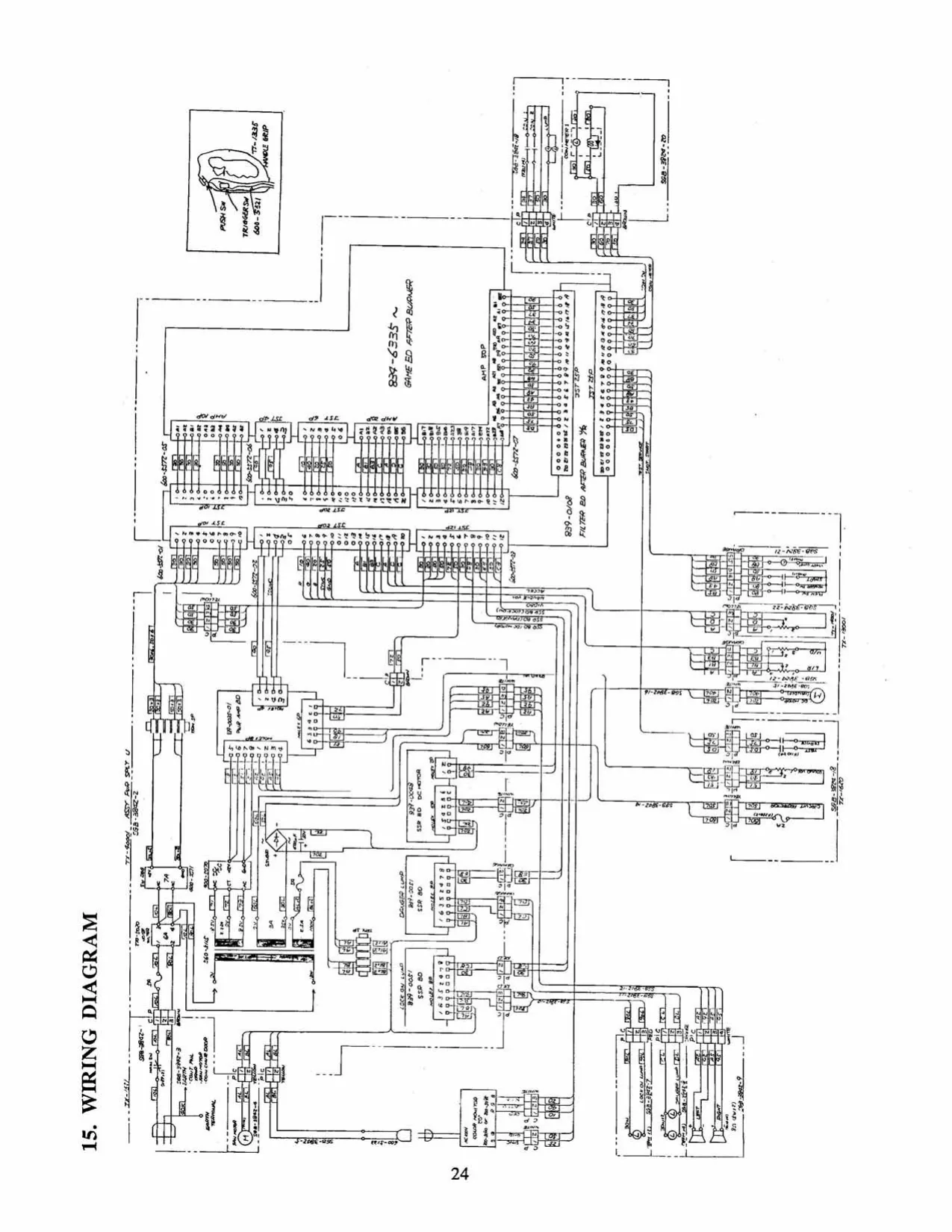
- WIRING DIAG
UPRIGHT TYPE
SPECIFICATIONS
INSTALLATION SPACE : 630 mm (24.8 in.) W x 860 mm (33.9 in.) D HEIGHT : 1850 mm (72.8 in.) POWER : 240W C.R.T. : 20" MONITOR WEIGHT : 124 kg (273 Ibs.)
- Descriptions herein contained may be subject to improvement changes without notice.
INTRODUCTION TO THE OWNER’S MANUAL
SEGA ENTERPRISES, LTD., supported by its high electronic technology of LSIs, microprocessors, etc. and a wealth of experience, has for more than 30 years been supplying various innovative and popular game machines to the world market. This OWNER’S manual is intended to provide detailed comments together with all the necessary infurmation covering the operation in general of electronic assemblies, electromechanicals, servicing control, spare parts, etc. as regards the AFTER BURNER U/R, a new SEGA product. The manual is intended for those who have knowledge of electricity and technical expertise especially in ICs, CR'I's, microprocessors, etc. Carefully read so as to acquire sufficient knowledge before working on the machine. Should there be a malfunction, non-technical personnel should under no circumstances touch the interior system.
- HANDLING PRECAUTIONS
When installing or inspecting, be very careful of the following points and pay attention to ensure that the player can enjoy the game safely. « Be sure to turn the power off before working on the machine. ¢ To insert or pull out the plug quickly is dangerous.
- Itis necessary to make sure that the power cord or the grounding wire is not exposed on the road, etc. in a manner so as to be dangerous. Make sure that grounding connections are made safely at the position where so specified.
- Donot use any fuse that does not meet the specified rating.
- Make complete connections for the IC board and other connectors. Insufficient insertion is very dangerous.
Also, for the IC board circuit inspections, only the logic tone is allowed. The use of a tester is not permitted, so be careful in this regard. After confirming that there are no irregularities, turn the power ON,
- PREVENTION OF COUNTERFEITING AND CONVERSION
LABELLING To prevent counterfeits and conversions, the following labels are put on all the SEGA products. When handling such goods, be sure to confirm the labels. They are used to prevent illegal acts such as the unauthorized copying of the products and the printed circuit boards thereof or carrying on business by manufacturing similar merchandise or by converting, selling or using such products or printed circuit boards.
ORIGINAL SEAL LICENSE SEAL The following seal is put on the The following seal is put on the kits, such as machines manufactured by SEGA. the printed circuit boards, of SEGA products.
SEGA AVF WE SEAL
COPYRIGHT NOTICE This SEGA product has the copyright notice as follows: © SEGA 1987
This signifies that this work was disclosed in 1987 and is the property of SEGA ENTERPRISES, LTD.
- PRECAUTIONS CONCERNING THE PLACE OF INSTALLATION
The SUPER AFTER BURNER UJR is an indoor game machine. Absolutely do not install it outside. Even indoors, avoid installing in places mentioned below so as to ensure proper usage: + Places subject to rain or water leakage, or condensation due to humidity. « In the proximity of an indoor swimming pool and/or shower.
- Places subject to direct sunlight.
- Places subject to heat sources from heating units, etc., or hot air. ¢ Vicinity of highly inflammable/volatile chemicals or hazardous matter.
- Sloped surfaces.
- Vicinity of anti-disaster facilities such as fire exits and fire extinguishers.
- Places subject to any type of violent impact. + Dusty places.
- NAME OF PARTS @®
SPEAKER
HANDLE GRIP
ASSY CABINET PLAY INST PLATE
ASSY THROTTLE ASSY CONTROL UNIT
COIN ENTRY
(TAMPERPROOF WRENCH) (TAMPERPROOF DRIVER) M 4 540-0006-01 M4 540-0018 M5 540-0007-01 MS 540-0017 M8 540-0009-01 M8 540-0011
- NAME OF PARTS @
FAN MOTOR
wororpessy ——
ASSY POWER SPLY
- OPENING THE CONTROL UNIT
TAMPER PROOF SCREW a j & j i J
M8 x 40
COIN CHUTE DOOR
oO Go ~|®
FLAT WASHER
‘SPRING WASHER MS
SCREW M5 x 25
- To open the CONTROL UNIT, take off the 4 TAMPERPROOF SCREWS (), open the COIN CHUTE DOOR, take off the 2 (M5 x 25) SCREWS @), and entire CONTROL UNIT will open towards you.
- Opening the CONTROL UNIT allows for spring replacements, handle centering V.R. adjustments, motor brush replacements and THROTTLE UNIT centering adjustments.
- HANDLE UNIT ADJUSTMENT
Tn the test mode, cause the DIAGNOSTIC INPUT DISPLAY to appear on the screen (to select it, push the test switch and move the handle upward and downward). DIAGNOSTIC INPUT TEST
COIN #1 OFF START COIN #2 OFF SERVICE
VALCAN OFF ‘MISSILE OFF
STICK RIGHT LEFT 80H STICKUPDOWN 80H SPEED © ©
- To make VR adjustments in a horizontal direction (RIGHT/LEFT), release the VR “A” bracket’s “A” screws and turn gear “A” in a manner so that when the handle grip is in an unoperated status, 80H + 2H is obtained. At this time, also make backlash adjustments. () When making vertical (UP/DOWN) adjustments, while maintaining the present inclination of the handle unit, unfasten the gear “C” bracket’s “B” screws and fasten the gear “C” bracket when the monitor display shows 80H + 2H. For backlash adjustments, loosen the VR “B” bracket.
- REPLACING THE MOTOR BRUSHES
TAMPER PROOF SCREW MB x 40
MOTOR
FLAT WASHER
‘SPRING WASHER M5
SCREW MS x 25
To replace the motor brushes, release the cap with a screwdriver, etc., and take out the brushes. Replacement once every 6 months is recommended. Make sure that both brushes are replaced at the same time.
- THROTTLE UNIT ADJUSTMENT
DIAGNOSTIC INPUT TEST
COIN #1 OFF START COIN #2 OFF SERVICE
VALCAN OFF MISSILE OFF GEAR
STICKRIGHT LEFT 80H
STICKUPDOWN 80H @
SPEED 80H
ADJUSTMENT SCREW
Unfasten the 2 adjustable screws to loosen the volume bracket, making sure that in relation to the gear engagement, the variable value in the test mode is within the allowable adjustment range, and then refasten the adjustment screws.
Reference value
Minimum = = Maximum
—-————————— Allowable adjustment range —-—-———————~-
- IC BOARD SVANDGND FORSOUND 10P 4P
INPUT VO 50P
+ HOW TO REMOVE THE IC BOARD
- Disconnect all of the harness to the filter board (839-0108) CONNECTORS.
- Take off the SCREW (M4 x 16 w/flat washer and spring washer) (@) which secures the SHIELD BASE.
- Completely pull out the SHIELD BOX, take off the 18 S TITE SCREWS (Mé4 x 6 w/flat washer) and remove the SHIELD COVER.
- Take off the 6 S TITE SCREWS (M3 x 12 w/flat washer) which secure the IC BOARD.
- The IC BOARD can be removed by taking off the inserted connectors.
- SERVICE SWITCH FUNCTIONS
The layout as shown below can be viewed by opening the coin chute door.
@© VOLUME ADJUSTMENT @ FUSE HOLDER
@ SERVICE SWITCH
@ TESTSWITCH
INSTRUCTIONS
® SERVICE SWITCH... .. Used for the purpose of servicing and increasing the credits without registering on the meter (this allows you to check the game). @ TEST SWITCH ........ccrecscecseesteces For operating this switch, see SELF-TESTING. @ VOLUME ADJUSTMENT .........++++ The volume of the speaker inside the cowl can be adjusted. ® FUSE HOLDER is sisisicss snssavecscesses When the motor is overloaded, the fuse will be burned out, causing the motor which is connected with the handle, to stop. To restart it, replace the fuse with same current limit.
- DIP SWITCH SETTING
COIN/CREDIT OPTION SWITCH SETTING DIPSWA
a ee ee OFF
- CREDIT OFF OFF OFF OFF 2CREDITS SCREDITS 1 CREDIT 1 CREDIT 1 CREDIT 1.GHEON 1 CREDIT
- CREDIT 3CREOITS:
2COINS: 3COINS SCOINS COINS
1 CREOIT SCREOITS
COIN ‘CREDIT 2COINS 2CREDITS SCOINS CREDITS coins, 4cREDITS SCOINS 6 CREDITS 1 CREDIT 2CREOITS: SCREDITS DCREDITS:
1 CREDIT SCREOITS COINSW1 COINSW2 ets 2 {| 3 [2] 3 [esesegegss
GAME OPTION SETTING DIPSWB BE EEE ppeAo movinc Ox | oFF | OFF CABINET MOVING STD | ON | OFF TYPE UPRIGHT | OFF | ON Notuseo | ON | ON ‘ADVERTISE OFF ‘SOUND ‘ON ‘SHIPSPER _SPLAYERS CREDIT 4 PLAYERS
DIFFICULTY HARD HARDEST
COIN METER
This page carries no recoverable text. It is a drawing or a photograph. See the original scan.
- EPROM/MASK ROM LOCATIONS
GAME BD AFTER BURNER 834-6335-01
OBJECT (CHARACTER & SCENE SCENERY)
je is FIXSCROLL IC 152 CHARACTER
Ic 58 Ic 63
aa MAIN PROGRAM
Ic 62
SOUND DATER
- PARTS LIST
ASSEMBLY CABINET PARTS LIST
| ITEM | PARTS NUMBER | DESCRIPTION | |
| 1 | 000-0525 | M SCR PH M5X25 (PANEL) | |
| 2 | 008-0516 | TMP SCR M5X16 (PANEL) | |
| 3 | 008-0535 | TMP SCR M5X35 (TV DOOR) | |
| 4 | 029-0099 | TMP SCR M8X40 (PANEL) | |
| 5 | 1050-0064 | MAIN SW. BRACKET | |
| 6 | 1170-0184 | TERMINAL BLOCK, 4P | |
| eA | 1170-5131 | TERMINAL BLOCK, 5P | |
| 8 | 1170-5131A | TERMINAL LUG | |
| 9 | 130-5018 | SPFAKER 8-OHM 10W W/SHIELD | |
| 10 | 1500-0173 | CAPACITOR, 4700 uF 50V | |
| 11 | 1500-0173A | CLAMP, CAP | , |
| 12 | 1502-0000 | POWER CORD RETAINE! | |
| 13 | 1710-5151 | FAN SCREEN COVER |
2000-5090 2141-5064 2200-0000 2200-5179 2600-0011-01 3901-5167 400-5070 400-5071 4211-6671 4810-0157 5090-0039 5090-5028 5140-0031 5240-0034 5140-0036 5140-0064 5142-0000 9600-5115 6010-0001 6010-0042 6010-0429 834-6335 839-0035-01 839-0048 839-0051 839-0108 KRO-1721 TX-13001 TX-1616 TX0-1623 TX1-1601-D TX1-1601-E TX1-1601-F TX1-1605 TX1-1608 TX1-1609 TX1-1610 TX1-1617 TX1-1618 TX1-1619 TX2-0000 TX2-0001 220-5130 509-0058 510-5009 540-006-01 540-0007-01 540-0009-01 601-5929 TX-1317 TX-1330 TX-1423 TV MONITOR LAMP SOCKET COIN DOOR VOL CONT B-5K FAN 110V LAMP 110V 30W DC/DC CONVERTER SW REGULATOR, 5V/7A STICKER, DANGER RECTIFIER, BRIDGE 2A PUSH BUTTON POWER SW PUSH BUTTON SW FUSE 6A, FAST FUSE 5A, FAST FUSE 3A, FAST (MOTOR) FUSE HOLDER 2P FUSE HOLDER, PANEL TRANSFORMER (160P6) FUSE COVER KNOB 22m LINE FILTER GAME BOARD POWER AMP DC12V 10W SSR BOARD, MOTOR SSR BOARD, LAMP FILTER BOARD SW BRACKET CONTROL PANEL ASSY WINDOW MASK ASSY BRACKET, WINDOW MASK, TOP STICKER, SIDE R STICKER, SIDE L STICKER, SEGA ORNAMENT PLATE, TOE GUARD MAIN BRACKET, CONTROL ORNAMENT SASH L ORNAMENT SASH L ORNAMENT SASH R SHIELD COVER SHIELD BASE ACCESS PLATE CORNER PROTECTOR, LEFT CORNER PRTOECTOR, RIGHT VOL CONT B-5K (SPARE PARTS) PUSH SW VALCUN (SPARE PARTS) PUSH SW MISSILE (SPARE PARTS) WRENCH, M4 (SPARE PARTS) WRENCH, M5 (SPARE PARTS) WRENCH, M8 (SPARE PARTS) MOTOR BRUSHES (SPARE PARTS) EXT. SPRING (SPARE PARTS) EXT. SPRING (SPARE PARTS) EXT. SPRING (SPARE PARTS)
QOOSS8 O@MOS8S
oe
- 101
CONTROLLER UNIT ASSEMBLY PARTS LIST
PARTS NUMBER ITEM
Oanhwn— TX-1351 TX-1352 TX-1318 TX-1334 TX-1307 MX-2017 100-5042 220-5130 601-5410 601-5423 000-0408-FS 000-0408-S 000-0412-FS 028-0003 028-0021 061-0006 054-0006 DESCRIPTION
SUB ASSEMBLY CONTROLLER ASSEMBLY SHOCK MECHANISM VR BRACKET A VR BRACKET B ADJUST PLATE ADJUSTER BEARING D=12 VOL CONT 5KOHM GEAR 15 D=16 GEAR 1/6 M SCR WI/FS M4 X8 M SCR WIFS M4 X8 M SCR WIFS M4 X 12 SET SCR PH SPECIAL M3 X 8 SET SCR PH SPECIAL M4 X 16 SPR WSHR M6 U NUT M6
OSS) So
THROTTLE ASSEMBLY PARTS LIST 0 08
ITEM PARTS NUMBER — DESCRIPTION
| 1 | TX-1418 | THROTTLE BASE |
| 2 | TX-1419 | VR BRACKET |
| 3 | TX-1402 | THROTTLE LEVER |
| 4 | TX-1403 | SWING ARM A |
| 5 | TX-1404 | SWING ARM B |
| 6 | TX-1405 | SHAFT SWING ARM |
| 7 | TX-1406 | GUIDE RING |
| 8 | TX-1423 | EXT. SPRING |
| 9 | TX-1003 | ADJUST PLATE |
| 10 | CY-2307 | ROLLER |
| 11 | KR-1303 | STOPPER PLATE |
| 12 | TX-1422 | STUD |
| 13 | TX-1430 | STOPPER BRACKET U/R |
| 101 | 220-5130 | VOL CONT B-5K OHM |
| 102 | 601-5424 | GEAR 30 |
| 103 | 601-5863 | GEAR 1/4 |
| 201 | 065-0004 | E RING 4mm |
| 202 | 065-0008 | E RING 8mm |
| 203 | 054-0006 | U NUT M6 |
| 204 | 000-0414-S | M SCR PH WIS M4 X 14 |
| 205 | 000-0408-FS | M SCR PH WIFS M4 X8 |
| 206 | 060-0010 | FLT WSHR M 10 |
| 207 | 045-0022 | COT PIN 2.5 X 20 |
| 208 | 028-0014 | SET SCR HEX SKT CP M4 X 4 |
| 209 | 000-0406-S | M SCR PH WIS M4 X6 |
| 210 | 054-0004-S | U NUT M4 |
HANDLE GRIP ASSEMBLY PARTS LIST
ITEM PARTS NUMBER
TX-1336 TX-1337 TX-1338 TX-1339 CD-2041 CD-2042 125-0011 839-0087 600-5521 509-0058 029-0052 029-0134 OCONOORWNH= yoo ooo pos DESCRIPTION
HANDLE GRIP LEFT HANDLE GRIP RIGHT BUTTON COMPRESSION SPRING TRIGGER SHAFT TRIGGER COMPRESSION SPRING SWITCH BOARD WIRE HARNESS, HANDLE GRIP MICRO SWITCH TMP PRF SCR PH M5 X 10 M SCR PH M2 X 10
OOOSS
FRONT MASK ASSEMBLY PARTS LIST
| ITEM | PARTS NUMBER | DESCRIPTION |
| 1 | TX1-1616-A | FRONT PANEL W/OUT MASK |
| 2 | TX1-1616-B | PLATE R |
| 3 | TX1-1616-C | PLATE L |
4 TX1-1616-D STICKER, AFTER BURNER
| 5 | TX1-1616-E | STICKER, SIDE R |
| 6 | TX1-1616-F | STICKER, SIDE L |
| 7 | TX1-1616-G | STICKER, JET NOZZLE R |
| 8 | TX1-1616-H | STICKER, JET NOZZLE L |
| 9 | TX1-1616-J3 | PLATE, LOCK-ON |
| 10 | TX1-1616-K | BRACKET |
| 14 | TX1-1616-L | GUARD PLATE, SPEAKER |
| 12 | TX1-1616-AX | SCREEN, CLEAR SMOKE |
| 201 | 008-0416 | TMP SCR M4X16 |
| 202 | 031-0414-B | CARRIAGE BOLT BLACK M4xX14 |
| 203 | 051-0004 | FLANGE NUT M4 |
OO
SIO) de
@S ©8
@]| ex’
Ga
CONTROL PANEL ASSEMBLY PARTS LIST
| ITEM | PARTS NUMBER | DESCRIPTION |
| 1 | TX-14001 | ASSEMBLY THROTTLE |
| 2 | TX-1341 | CON PANEL BASE |
| 3 | TX-1342 | FLAG PLATE |
| 4 | TX-1343 | SHLDER SCREW |
| 5 | TX-1344 | COVER |
| 6 | TX-1345 | GUIDE PLATE |
| Z | TX-1346 | SLIDE PLATE A |
| 8 | TX-1347 | SLIDE PLATE B |
| 9 | TX-1366 | HINGE 590 |
| 10 | TX-1348 | CONTROL PANEL COVER |
| 11 | TX-1350 | ASSEMBLY CONTROLLER |
| 12 | TX-1349 | THROTTLE COVER |
| 13 | TX-1367 | COVER HOLDER |
| 14 | TX-1335 | ASSEMBLY HANDLE GRIP |
| 15 | TX-1310 | HOLDER A |
| 16 | TX-1356 | PROTECT TUBE |
| 17 | HN-1069 | RUBBER CUSHION |
| 18 | 422-0209 | PLAY INSTRUCTION PLATE |
| 19 | TX-1369 | FLAG |
| 20 | TX-1370 | COVER A |
| 101 | 509-5050 | START SWITCH W/LMAP |
| 201 | 059-0014 | WELL NUT M4 |
| 202 | 001-0406 | M SCR FH M4 X6 |
| 203 | 008-0408 | TMP PRF SCR M4 X 8 |
| 204 | 008-0416 | TMP PRF SCR M4 X 16 |
| 205 | 029-0052 | TMP PRF SCR M5 X 10 |
| 206 | 08-0516 | TMP PRF SCR M5 X 16 |
| 207 | 008-0520 | TMP PRF SCR M65 X 20 |
| 208 | 000-0516-FS | M SCR PH WIFS M5 X 16 |
| 209 | 000-0525 | M SCR PH M5 X 25 |
| 210 | 061-0005 | SPR WSHR M5 |
| 211 | 054-0005 | U NUT M5 |
| 212 | 069-0064 | FLT WSHR BLK 5.5-20 X 6 |
| 213 | 008-0525 | TMP PRF SCR TH M5 X 25 |
| 214 | 005-3113-F | W SCR PH WF 3.1 X 13 |
BOB
© O©0OOO OOGO
SHOCK MECHANICAL UNIT PARTS LIST
| ITEM | PARTS NUMBER | DESCRIPTION |
| 1 | TX-1353 | MAIN BASE |
| 2 | TX-1354 | MOVING BASE |
| 3 | TX-1357 | MOTOR BRACKET |
| 4 | TX-1358 | SLIDE PLATE BOTTOM |
| 5 | TX-1359 | SLIDE PLATE SIDE |
| 6 | TX-1360 | GUIDE WASHER |
| 7 | TX-1361 | SHOULDER SCREW |
| 8 | TX-1362 | ROD |
| 9 | TX-1363 | CAM |
| 10 | TX-1364 | SHAFT |
| 12 | TX-1325 | SPRING BRACKET |
| 13 | TX-1326 | FRONT GUIDE |
| 14 | TX-1327 | SIDE PLATE |
| 15 | TX-1328 | SHAFT B |
| 16 | TX-1329 | PIPE |
| 17 | TX-1330 | EXT. SPRING |
| 19 | TX-1331 | HOLDER L |
| 20 | TX-1332 | HOLDER R |
| 21 | TX-1333 | BUMPER B |
| 102 | 350-5113 | MOTOR DC45V |
| 201 | 000-0412-FS | M SCR M4 X 12 |
| 202 | 001-0414 | M SCR M4 X 14 |
| 204 | 000-0510-FS | M SCR M5 X 10 |
| 205 | 000-0512 | M SCR M5 X 12 |
| 206 | 029-0035 | M SCR M6 X 12 |
| 208 | 060-0008 | FLT WSHR M8 |
| 209 | 060-0010 | FLT WSHR M10 |
| 211 | 061-0006 | SPR WSHR M6 |
| 212 | 065-0006 | ERING 6mm |
| 213 | 045-0022 | COT PIN 2.5 X 20 |
| 214 | 054-0004 | U NUT M4 |
| 215 | 054-0006 | U NUT M6 |
| 216 | 054-0005 | U NUT M5 |
| 217 | 000-0305-S | MSCRM3X5 |
| 218 | 028-0012 | SET SCREW SPECIAL M5 X 12 |
| 219 | 045-0014 | SPR PIN 3 X 26 |
This page is a drawing, shown as the original scan.
SEGA ENTERPRISES, INC. (USA)
2149 Paragon Drive
San Jose, CA 95131 Tel (408) 435-0201 @SEGA 1987