Robot Bowl
Robot Bowl (Exidy, 1977) · Manual · 23 pages · 49 sections · original scan
ROBOT BOWL
BY EXIDY
SERVICE
MANUAL
TABLE OF CONTENTS
[General Information 3.25600 caw ene os dese hea pete ae cae ees 1
He Hosrpal Operation ~ 2.2.6.5 ie te mie ah ek ee case ea wind bie de 1
ML, To Remove Monitor... 6. see cece rete tenet eee eee eteeeens 2
IV. To Remove Microprocessor... 1.02.0 e sees cece eect eee eeeeees 2
V. Pushbutton Control Panel .......... cece eee tee e eee eee 3
Vi Adlustments jscc,ccetn gree yer eee tae oot ne eM BED 4
VIL. Theory of Operation, Logic . 7
VIII, Theory of Operation, Audio. 6... 6. ce eee erect eee eee eee 8
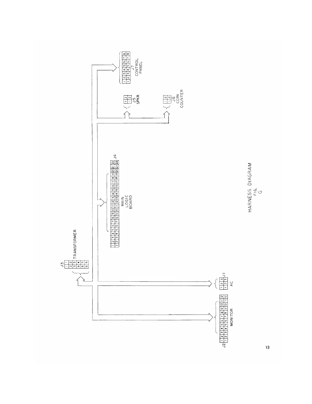
IX. Harness Diagram... eee eee eee tence ee 13
X. Schematic Diagrams 22... . 26 eee cee eee eee eens 14
LIST OF ILLUSTRATIONS
Figure A we eee cece eee eee ener ee een eee e nent eens Cabinet Interior
Figure B . . . . Switch Assembly Access Diagram
Figure C . . Logic Power Supply Adjustment Points
Figure Oy Sapneety ee see eee eee pry Audio Board Adjustment Points
Figure Eo... 2. eee eee eect eee eee Logic Board Block Diagram
Figure Foo... cece cece e ee tenet e eee eee Audio Board Block Diagram
Figure 6... cece cc ence cece cece teen e eee eeneee Harness Diagram
Fa Boo aconnononooeg sop nor yon coonpedaeoood Schematic Diagrams
|. GENERAL
ROBOT BOWL is a one or two player video game simulating all ‘the elements of an actual bowling game. The player controls the position of the bowler, selects how fast he rolls the ball, and can correct the ball movement with a left or right hook. The audio sounds include his footsteps as he walks out to bowl, the clunk of the ball as it hits the alley, the roar as it rolls toward the pins, and the clatter when it hits them.
I, NORMAL OPERATION
When the game is first powered up, “GAME OVER” is written at the top of the screen, and “DEPOSIT COIN”, and either:
Two Player — 1 Coin or One Player — 1 Coin Two Player — 2 Coin or One Player — 2 Coin Two Player — 4 Coin
depending on the setting of the option selection switch. This is then erased to allow the bowler to walk from the edge of the
&
PLAYER ONE screen to the center, where he turns and rolls the ball, The bowler is then erased and the attract message is flashed again,
When a coin is deposited, the message “ROBOT ROLLS BALL
AUTOMATICALLY AFTER X SECONDS, PRESS START”, is flashed on the screen (X being the number of seconds selected by the operator at the option selection switch).
When the start button is depressed, the bowler walks out (starting from the left side for Player 1) to the center of the screen and turns sideways. At this time, control is transferred to the player so that he can position the bowler using the “MOVE BOWLER” Left or Right buttons. The player then rolls the ball using the “ROLL BALL SLOW” or “ROLL BALL FAST” control. Note that if the player has not rolled the ball by the end of the time set by the operator (3, 5, 7 or 9 seconds), the machine rolls it for him. Once the ball has been rolled, the player still has control over it by using the “HOOK BALL LEFT” and “HOOK BALL RIGHT“ controls.
The normal audio consists of footsteps as the man walks out, the clunk that the ball makes when it hits the alley, the noise that it makes as it rolls toward the pins, and a clatter of pins as it strikes them down.
PLAYER THO
I, TO REMOVE MONITOR
Disconnect power cord from AC outlet. Open and remove back door. Remove connector from monitor (Item 1 Figure A). Remove four bolts from monitor chassis flang mounts. Lift back of monitor up 4’"- 6" and slide monitor out of the cabinet, SRON> IV, TO REMOVE MICROPROCESSOR PRINTED CIRCUIT BOARD
- Disconnect power cord from AC outlet. . Open and remove back door. . Clip microprocessor tie wrap at locations 3 and 9. . Disconnect edge connector (Item 4) from microprocessor PCB. Slide microprocessor out of rack, BONS
5.
MAJOR INTERNAL COMPONENTS (FIGURE A)
1. MONITOR POWER SUPPLY (See Figure C Detail) 3, MICROPROCESSOR TIE WRAP (1 of 2)
- AUDIO POWER SUPPLY TRANSFORMER
- MICROPROCESSOR CONNECTOR
- MAIN HARNESS CONNECTOR
- IN LINE 5 AMP FUSE 7, AC POWER CORD
- AC INTERLOCK SWITCH
- MICROPROCESSOR TIE WRAP (2 of 2)
- MICROPROCESSOR VIDEO PCB
- MICROPROCESSOR OPTION SELECTION SWITCH LOCATION
- COIN COUNTER
- MICROPROCESSOR AUDIO PCB
V. ROBOT PUSHBUTTON CONTROL PANEL (Figure B)
Design: Robot Bowl uses Bally pushbutton controls in a wafer switch assembly. The pushbuttons secure a wooden spacer and printed circuit board with leaf switches to a steel control panel that is hinge mounted to the cabinet and swings open for front access. Procedure:
To Open Panel:
- Open front double coin door.
- Reaching up through the coin door, remove right and left wing nuts and fender washers (Item 7, location 6) from underside of control panel.
- From the underside of the control panel push the panel up (Item 8) and swing the panel out towards you. (CAU-
TION: Do not push against the leaf switches.)
- Remove the loose carriage bolts (Item 7) from the panel.
To Remove the Entire Panel:
- Remove three carriage bolts (Item 2) from hinge (Item 1) and lift the panel from the game. To Service Switches:
1, Check connector (Item 4),
- Check leaf switches (Item 3) for contact, damage or cleaning.
To Remove Switches and Push Buttons:
- Disconnect connector (Item 4) from switch PCB (Item 10). 2, Detach switch PCB (Item 10) from wooden spacer (Item 9) by removing self tapping screws (Item 11),
- Switches may now be removed from PCB and replaced individually or the entire PCB may be replaced.
- Bally pushbuttons (Item 5) may be removed individually for replacement or cleaning.
To Retouch Control Panel Finish:
The ROBOT BOWL control panel is a steel panel coated with a flat black enamel (Sherwin Williams Polane Black). This allows the panel to be touched up with black spray paint,
9 8 7 ROBOT BOWL PUSHBOTTON CONTROL PANEL (FIGURE B)
- PANEL HINGE
- HINGE CARRIAGE BOLTS (3 each)
- LEAF SWITCH (7 each) 4, CONTROLS CONNECTOR
- BALLY PUSHBUTTON
- CABINET BRACKET 7, CABINET TO CONTROL PANEL FASTENER
(CARRIAGE BOLT, FENDER WASHER, WING NUT)
- STEEL CONTROL PANEL
- WOOD PCB SPACER
- LEAF SWITCH PCB
- SELF TAPPING SCREW (12 each)
Vi. ADJUSTMENTS
A. Power Supply Adjustment
- Adjust the power supply “adjust potentiometer” located 1, Connect the voltmeter leads to +5 and ground traces on (on the back of the monitor (Item 1 in Figure C) for the main logic board, +5,0VDC +.1VDC.
POWER SUPPLY ADJUSTMENTS (FIGURE C)
1.5 VOLT LOGIC SUPPLY ADJUSTMENT 2.5 VOLT LOGIC SUPPLY FUSE
B. Audio Adjustments (See Figure D)
FOOTSTEPS — No adjustment BALL DROP — Adjust volume using Item 6 {Pot R60) BALL ROLL — Adjust volume using Item 5 (Pot R29) PIN HIT — Adjustment has three pots- 1, Adjust Item 3 (Pot R39) fully CCW when viewed as in Figure 4. 2, Set Item 2 (Pot R49) approximately 3/4 CCW when viewed as in Figure 4,
- Adjust Item 1 (Pot R47) for a tone approximating sound ofa pin when hit. This must be done while actually playing the game. 4, When Item 1 seems properly adjusted, Item 3 must be readjusted to add “crash”” sound to tone sound. Item 3 varies the relationship (mix/ratio) of “tone” to “crash” sounds.
- Once this relationship has been set, volume (if touch-up is necessary) can be adjusted by Item 2.
- To summarize PIN HIT adjustment: Item 1 adjusts tone frequency. Item 2 adjusts volume, Item 3 adjusts ratio of “tone” to “crash”. REWARD & DEMERIT (STRIKE AND GUTTERBALL) — Adjust volume using Item 4 (Pot R63) TONE — Adjust item 7 (Pot R65)
AUDIO P.C. BOARD (FIGURE D)
1, R47 — PIN HIT TONE FREQUENCY ADJUSTMENT 5. R29 — ROLL SOUND VOLUME ADJUSTMENT
- R49 — PIN HIT VOLUME ADJUSTMENT
- R39 — PIN HIT TONE/CRASH RATIO ADJUST- MENT
- R63 — REWARD & DEMERIT VOLUME ADJUSTMENT
- R60 — DROP SOUND VOLUME ADJUSTMENT
- R65 — MASTER TONE ADJUSTMENT
- OPTION SELECTION SWITCH
C. Switchable Options
There are 3 switch selectable options on the bowling board. The seven position switch used to select these is located at location 14A on the main logic board (See Figure D Item 8), and is accessible from the front of the game.
The first two switches select the time that the robot takes to automatically roll the ball. Note that the setting of this switch sets the overall time of the game.
| Time | swt | sw2 |
| 3 seconds | On | On |
| 5 seconds | On | off |
| 7 seconds | off | On |
9 seconds Off Off
‘Switches three and four control the coinage necessary to operate the game. Coinage sw3 sw
2 players — 1 coin off oft 1 player — 1 coin
2 players — 2 coins Cn ore
1 player ~ 2 coins on on 2 players — 4 coins
‘Switch 5 is used to enable the optional beer frame. The beer frame is enabled when switch 5 is off.
‘Switches 6 & 7 are not used at this time.
Vil, THEORY OF OPERATION, LOGIC (Refer to Figure E)
ROBOT BOWL is a microcomputer game which uses the MOS technology 6502 central processor unit. (For more information on this processor, refer to MOS technology publication #6500- 10A, MCS 6500 Microcomputer Family Hardware Manual.)
This processor is unique in that it doesn’t have a separate input/ output structure but rather treats all I/O as if it were an area in memory. Memory is subdivided as follows:
FFFS — FFFF Interrupt and reset vectors F000 — FFF8 Program storage (ROM) co00 Option switches (Input) A000 Control switches (Input)
8000 Output bits (Output) 3000 Ball horizontal position (counters)
4000 — 43FF Screen RAM
2000 Ball vertical position (counters) 0100 - O1FF Stack RAM 0000 — OOFF Page 0 RAM
Page 0 RAM is used for storage of dynamic variables during Program execution, and Page 1 RAM is used as the stack, to store return addresses and important data during subroutine execution. The program ROM is where the program that controls the operation of the game is stored. The Screen RAM consists of 1024 bytes (8 bit words) of read/ write memory which, when not being addressed by the processor, are scanned by main timing to display a matrix of 32 x 32 squares on the screen. The data stored in the screen RAM is then used to address one of 256 8-element wide by 8-line high blocks in the Screen ROM, These 8 x 8 blocks stored in ROM then contain images or portions of images to be displayed on the screen. (An alphanumeric character takes one block to be stored, where an image, such as the robot takes up to nine.)
Example: To store a letter “X"’ in the upper left corner of the
sereen, the processor would write a 29H in location 4000H. Then by combining the 256 different portions of images, a large combination of different images can be produced.
The same circuitry that produces syne and scans the screen RAM is also used to generate the horizontal and vertical lines which form the score boxes and alley lines. It does this by reading two PROMs and combining their outputs with various ig signals.
The ball is generated by two sets of counters (horizontal and vertical) which are used to locate the ball on the screen, The outputs of the counters are fed to a PROM and then a shift register to form the ball video. The processor controls the ball by preloading the counters to the desired position during vertical sync,
The processor reads data from the switches by gating the data from the control or option switches onto the data bus.
baad ADORESS BUSS
: [maces [wore og —
° SYN RATION
ROBOT BOWL BLOCK DIAGRAM
THEORY OF OPERATION, AUDIO (REFER TO FIGURE F)
The ROBOT BOWL audio is comprised of eight rather distinct
circuits, one of which can be further subdivided into four fairly
distinct circuits (this is the PIN HIT SOUND GENERATION CIRCUIT). Their general operational descriptions follow.
+15Vdc Power Supply
This circuit provides the V¢c (main power) for the majority
of the audio. It consists of diodes CR 1, CR2, capacitor C2, zener
diode CR3, transistor Q1, and associated support components.
Diodes CR1 and CR2 form a full wave rectifier whose output is filtered by capacitor C2, This rectifier converts the input 22-26 VAC into a DC level of approximately the same (actually slightly less) voltage. Zener diode CR3 holds the DC voltage at the base of Q1 to +15V.
This voltage at the base of 1 is used directly as a power source — see audio amplifier circuit description)
for all audio circuits except the audio amplifier (the LM380's
- see audio amplifier circuit description).
Since Q1 is configured as an emitter follower, a higher current regulated supply is available from the emitter than from the base junction. It is regulated due to the fact that the voltage at the emitter will always “follow” the voltage at the base; that is, the emitter voltage will be approximately the same as the base voltage (minus the drop across the base-emitter junction of 0.7V). In this way we have two regulated +15Vde supplies, one providing more current than the other. The higher current supply (+15VR — from the emitter) is used solely to provide power for the rather current hungry LM380 audio amplifiers. White Noise Generator
“WHITE NOISE” simply defined is random noise, usually across a broad frequency spectrum. Some good examples are the sound of the seashore, rapids on a river, a waterfall, or the background hiss on your radio or television.
Since this type of noise has such a wide range of frequencies and is so random, it is a very good source of sounds which can be isolated and used for other purposes.
To produce this white noise we make use of the thermal breakdown characteristics of a transistor junction. Referring to audio schematic page one, you will note that Q2 has a grounded base, an open circuited collector and the emitter has a current path to +15Vde. This reverse biases the base-emitter junction to the degree that the junction “breaks down” and a great deal of electron agitation takes place, This agitation creates our white noise.
This white noise is still very small, however, so it must be amplified. This is the job of operational amplifier U1 (72748).
The output of the operational amplifier isa very high impedance source, and would, therefore, be easily loaded down by the input stages of all circuits using white noise. To prevent this,
and also to add a small amount of further amplification, a single
stage transistor amplifier (Q3) interfaces between the operational amplifier and other circuitry. The output of transistor amplifier ‘23 is a low impedance source and will therefore drive many other circuits with negligible loading effects.
+15 VOLT
Ce TEND)
+15 VOLTS
i waite
NOISE
GENERATOR
REGULATED FISVOLTS REG.
Power
SUPPLY
+15 VOLTS: g BALL DROP ‘SOUND
WHITE NOISE
RANDOM aT CLOCK
+5 VOLTS g 45 ¥OLTS oo BALL ROLL, ‘SOUND
+15 VOLTS HIS VOLTS it i
ACTIVE FILTER PIN HIT AMPLITUDE
re s15yours aren a2 AMPLIFIER
Pin HIT SOUND
(CRASH-SOLND) TONE GENERATOR MODULATOR
REWARD TONE GATE
REWARD ENABLE REWARD TONE. BALL OROP: DEMERIT TONE GATE
DEMERIT ENABLE GOL AUDIO ENABLE GATE /
(Gin +S vouTs J VIDEO INVERT
oeovERT DEFLECTION com =
RELAY ORIVER (INVERTS viDEO) FIG.F AUDIO BLOCK DIAGRAM TENERGIZES. RELAY)
Ball Drop Sound Generator
Generation of the ball drop sound is accomplished through the Use of a simple one transistor oscillator (12) using a resistor/ capacitor feedback network consisting of C32, C33, C34, and R55, R56.
Under normal conditions (no ball drop enable present), the base of 012 is held at a potential too low for the oscillator to operate, When signal “BALL DROP” goeshigh (TTL level high), capacitor C31 charges through diode CR17 and the internal collector resistor at the driving TTL chip, toward +5V. This effectively raises the potential at the base of Q12 so that it may oscillate.
White noise is fed into the base also, This has two functions,
One is to help stimulate the oscillator into operation; the other
is to provide a measure of randomness to the operation,
When the TTL signal “BALL DROP” is removed, capacitor C31
discharges through resistor R53, providing a sloping trailing edge to the oscillation. (The sound dies out gently, rather than having a sharp cutoff.) Note that when the TTL signal (“BALL DROP”) drives low, diode CR17 becomes reverse
biased and prevents capacitor C31 from discharging immediately
through the TTL chip.
Diode CR16 provides isolation between the white noise generator and the input of the oscillator (primarily to prevent interference with the DC bias level at the base of Q12. Diode CR18 {at the collector of Q12) also provides isolation.
The output of this circuit is then fed through a volume control to the input of the audio amplifier. Ball Roll Sound Generator
The ROLL SOUND is accomplished by using the white noise and an active filter network consisting of Q6 and supporting components.
Here’s How It Works:
In the absence of the TTL signal “ROLL,” the base of Q6 is held sufficiently low to prevent Q6 from operating, When “ROLL” is applied, capacitor C15 charges through CR7 and R20 toward +15Vde.
This raises the base level of Q6 and allows it to amplify. The white noise is what it amplifies, but note that there is a feedback network from the collector to the base, consisting of C16, C17 and R27. This network is tuned to a range of frequencies, and Q6 will therefore amplify certain frequencies more than others. In this way we select certain frequencies out
of the white noise and make special use of them, In this case,
of course, we select the combination of frequencies that most closely approximates the sound of a rolling bowling ball,
Resistor R22 and capacitor C14 form an alternate (or parallel) input path (to the base of Q6) whose impedance changes with frequency. It therefore appears to be a lower value resistance at higher frequencies, providing more base current, and thus pre-emphasizing higher frequencies.
When TTL signal “ROLL” is removed, capacitor C15 discharges through resistor R24, creating a sloping trailing edge, to eliminate a sharp cutoff to the sound.
Diodes CR6, CR7, CR8 provide isolation identical to CR16, CR17 and CR18 as discussed in the description of the BALL DROP SOUND GENERATOR.
Output of the ROLL SOUND GENERATOR is then fed through a volume control to the input of the audio amplifier.
Pin Hit Sound Generator
The PIN HIT SOUND GENERATOR is most easily understood when separated into four basic circuits. These are the RANDOM CLOCK GENERATOR, the ACTIVE FILTER (or crash sound generator), the TONE GENERATOR and the AMPLITUDE MODULATOR.
The RANDOM CLOCK GENERATOR consists of a two-stage transistor amplifier (Q4, Q5), whose task is to translate white noise into a random square wave with high current drive capability and TTL logic levels, and counter U2, whose task is to divide down the “frequency” of the random clock created by Q4 and Qs,
You will note that the TTL signal “HIT” is tied to the “clear” input on the counter. When “HIT goes high it allows the counter to count. The output of the counter (labeled CRASH ENABLE on the schematic) is fed to two places, one the enable input of the ACTIVE FILTER, the other the input of the TONE GENERATOR.
The ACTIVE FILTER (or crash sound generator) is aduplicate of the BALL ROLL SOUND GENERATOR discussed above. Since it is enabled by a random pulse train, however, its output becomes a random grouping of filtered noises. After passing through a volume control, this noise (labeled HIT SOUND on schematic) then proceeds to US pin 2, which is the control line for the AMPLITUDE MODULATOR. But first let’s look at the TONE GENERATOR, which, as previously mentioned, is also enabled by the CRASH ENABLE output.
At the input of the TONE GENERATOR circuit are three transistors — Q9, Q10 and Q11 — which form a wave-shaping circuit. Their purpose is to create a negative-going ramp with a slope determined by capacitor C23. This “sloping ramp” signal, when applied to the input of U4 (a function generator), causes the frequency generated by U4 to rise as the input level drops,
That is, as the DC level applied to U4 pin 5 approaches ground,
the output frequency (at pin 4) increases. You will recall, however, that the input to the waveshaping portion of this circuit
the output frequency (at pin 4) increases. You will recall, how was quite random, This means that we will end up with arather
jumbled, somewhat ameliorated input to the function generator
(U4). This gets us somewhat close to the sound of bowling Pins being hit, but needs some amplitude modulation now.
As was previously explained, the output of the ACTIVE FIL- TER (labeled “HIT SOUND”) is tied to pin 2 of US (THE AMPLITUDE MODULATOR). The output of the TONE GENERATOR is now tied to the input of US (pin 1). The outut signal resulting will be the random tone of U4 (the function generator) amplitude modulated by the “HIT SOUND.” This is then run through a volume contro! to the input of the audio amplifier. Audio Enable (Game)
TTL signal “GAME” enables or disables all audio by appearing
as an open circuit (using open collector gates) or aground to the
‘common audio input line, thus grounding all incoming signals.
Audio Amplifier
The audio amplifier consists of two LM380 ICs configured as one push-pull amplifier. As you see on the schematic, one side of C29, C30, C39, C36 and C37 are all tied together. This is a common input bus to the amplifier.
Any signal appearing on this line passes through C39 and R66 directly into the inputs of the LM380's. Note that this input goes to the inverting (-) input on one LM380, and the noninverting (+) input on the other LM380.
In a sense this puts the individual amplifiers in series and their output power is approximately doubled,
Capacitor C38 and pot R65 form a shunt filter used for tone control. Less resistance across R65 means less resistance to ground at higher frequencies, thereby eliminating higher frequencies prior to amplification. More resistance across R65, therefore, means more high frequencies make it through to the amplifier.
Capacitors C42 and C43 provide DC bias isolation.
Video Inve
There is one last circuit located on the Audio Board whose function is unrelated to audio. This is the circuit provided for inverting the image on the T.V. monitor. That is, in a game model (such as a cocktail table) where it is desirable to turn the image “upside down,” we must accomplish this by reversing the T.V. monitor deflection coil leads. We do this with a relay that is driven by a power transistor (Q8) located on the audio board. CR12 serves as a spike suppressor, to prevent destruction of 08 by “back EME,” which is a voltage spike created by the collapse of the magnetic field built up in the coil of the relay while it was energized.
Transistor Q8 is enabled by TTL signal “VIDEO INVERT” from the logic board
W
a “BulytAue 07 payoouuoo rou pus eyo — ssowey 42 YrIM UL palpuNg e11m Guo] gL = VNNALNW OILVIS, | unos HOLIMS MOTS HOLId ver oor HOLIMS dO¥a NIOO zee NIOO HOLIMS 1431 HOOH our sor N09 HOLIMS LHDIY HOOH | cer Lor 920A ger} — NIOoo HOLIMS LSV4 HOLId sur oer HOLIMS LUWIS 3WV9 ber sor annous oaain , ober ror Addn'S Y3MOd ez zor eur NuNLay OaGIA wer cor HOLIMS LUVLS 3WV9 | sor) bur aNd | eer zor HOLIMS LHOIY HOOH Lor our 200 | ger Ler HOLIMS L437 YOOH sor sur | HOLIMS MOS HOLId ovr ver LOOWA zz vibe ger HOLIMS LSV4 HOLId oor eur DVA zz si-vr ser HOLIMS LHOLW NV oer) ear OVA zz ot-pr ver HOLIMS 1337 NV Lie ber anno Alddns ¥3MOd eu eer annoya | yaMod eur wer Alddns ¥3MOd eur eer zor ¥3MOd G3HOLIMS tir ber ¥aLNN09 | HOLIMSdOHONIOD| NiO | —zt-#r L-or aA g'0L ever wanvads | beer zor Lier uayvads | oer usr 43Mod zur} ober YaMOd G3HOLIMS br eer | ze-vr “WldS HOLINOW eer no uavads zsr) ier |} annoys ann wamod eur Ler Ano ¥ayVv34s ber | opr 200} ONIOo Ler ger el-er “wdS HOLINOW | ; ser +AV13H | ] slo NI dv olany ver ~ AWAY | | ceer annous OWA zz rer) olor AddnS Y3MOd zor} ter exe Ova zz ser) ster NYNL3Y O3GIA er er LOOWA 22 | ; 98h) peer O301A rer) ber «VNNALNY O1LWLS eter HOLIMS do¥a NIOD | ONIOD vor! zi-pe || aNnows aNi7 w3Mod eer Ler eu HOLIMS L337 NV eer) beer 4aMod zer| ober eur HOLIMS LHOIY NVW exe | ober Y3MOd GAHOLIMS Ler ez} bir TvNOIS GNv OL Nid TWNOIS anv OL Nid 9 3YuNdI4
This page is a drawing, shown as the original scan.
E266 1e te = i
NOTES RS tac0 senies rn ane vow Pome seworrer
EXIDY ING. ROBOT BOWL LOGIC DIAGRAM | PAGE 10F6 MASTER TIMING.
ry NOILWY3N39 O3CIA
9402 39¥d
Wy¥OWIG 31907 WMOd 10808
“INE AGIXS) rar oe losing
o Fr vee]
1 Hoe ae --| i 4 —— ; T=
- i =|, =
7 ill ap cn —"e e, a
- j-20veh fp 7a | -— 7 i ait tH 3 °° % TK ser0 = { jenieget
L
5 om | A 13, ed
: I-zorzbe ‘ai i Lh oe
o30n m——
J) avi
leesieate— wie
i ) BEL) eq 140 Lt es parses
samen Sony i BALL GENERATION
PAGE 30F6
ROBOT BOWL LOGIC DIAGRAM
EXIDY INC.
F me >29 svorrs THTTTT We 282
siease.
DIP SwiTCH _/ 220! T cre ‘Riad fWd001
cow paar.
a = ers7= al
7465 105 suiupr PP ca tt > CED
22 PINEDEE Eonneon coup vibeo ar)
Low powenscnortKY Neo ranas
EXIDY INC. ROBOT BOWL LOGIG DIAGRAM PAGE 40° 6. INPUT / OUTPUT
i}
TINA ONISS3I0Nd WHLNID
940 S 30%
WyudvId 91907 Woe LOBOY
“ONT AGIKS)
9309 39va | Wwv8ovId 91907 1MOE 1OBOU
Tm
ah
41s youts
+ suoirs, t 9
ce cr peeve + ysvourg aes ice
one rrom ) Capeeuc xronmen § Cl 415 vours
cra map oes cre NeKS nda
+5 yours vores
+5 vours pauoom chock
JL CsoHt (race 2)
EXIDY INC. ROBOT BOWL SCHEMATICS PAGE 1OF 2 AUDIO
+15 vours +15 yours REG,
eee : CR _—
415 vours be ose tf Ee} 41s yours
ig Ase PAGE 20F2
ROBOT BOWL SCHEMATICS
AUDIO
NOTES, ee LE Secsstons sae cus AND ane aw UNLESS rhe TREE tm BNO ane
- ibwhde Unless Othemwise SorcieieD
EXIDY INC. a}