Gauntlet TM-284 1st Printing
Gauntlet (rev 14) (Atari Games, 1985) · Technical Manual · 76 pages · 80 sections · original scan
This page is a drawing, shown as the original scan.
Atari Games Corporation Customer Service
If reading through this manual does not lead to solving a certain maintenance problem, call TELEHELP® at one of these Atari Games Customer Service offices:
UNITED STATES
Parts and Service
California Customer Service Office 737 Sycamore Drive P.O. Box 361110 Milpitas, CA 95035-1110 Telex 17-2976 (Monday-Friday, 7:30-4:00 pm Pacific Time) LO" (408) 434-3950
EUROPE
Parts and Service
European Customer Service Office Tipperary Town, Ireland Telex 28165 (Monday-Friday, 9:00-6:00 pm GMT) = 062-52155
Gauntlet’ Operators Manual
with Illustrated Parts Lists
AL
Gauntlet
© 1985 by Atari Games Corporation All rights reserved No part of this publication may be reproduced by any mechanical, photographic, or electronic process, or in the form ofa phonographic recording, nor may it be stored ina retrieval system, transmitted, or otherwise copied for public or private use, without permission from the publisher. The game play, all graphic designs, this technical manual, its accompanying schematic diagrams, and the display manual are protected by the U.S. Copyright Act of 1976. This Act provides for increased penalties for violating federal copyright laws. Courts can impound infringing articles while legal action is pending. If infringers are convicted, courts can order destruction of the infringing articles. In addition, the Act provides for payment of statutory damages of up to $250,000 in certain cases. Infringers may also have to pay costs and attorneys’ fees and face an imprisonment of up to five years. Atari Games Corporation will aggressively enforce its copyrights against any infringers. We will use all legal means to immediately halt any manufacture, distribution, or operation of a copy of video games made by us. Anyone who purchases such copies risks forfeiting such agame,
Published by: Atari Games Corporation P.O. Box 361110 Milpitas, California 95035
Printed in the U.S.A. 10P
Notice Regarding Non-ATARI Parts
-——— x WARNING Use of non-ATARI® parts or modifications of any ATARI game circuitry may adversely affect the safetv of your game, and may cause injury to you and your players.
You may void the game warranty (printed on the inside back cover of this manual) if you do any of the following:
- Substitute non-ATARI parts in the game. © Modify or alter any circuits in the game by using kits or parts not supplied by Atari Games Corporation.
NOTE
This equipment generates, uses, and can radiate radio frequency energy and if not installed and used in accordance with the instruction manual, may cause interference to radio communications. It has been tested and found to comply with the limits for a Class A computing device pursuant to Subpart] of Part 15 of Federal Communications Commission (FCC) Rules, which are designed to provide reasonable protection against such interference when operated in a commercial environment. Operation of this equipment in a residential area or modification to this equipment is likely to cause interference in which case the user, at his own expense, will be required to take whatever measures may be required to correct the interference. If you suspect interference from an ATARI® game at your location, check the following:
- All green ground wires in the game are properly connected as shown in the game wiring diagram. © The power cord is properly plugged into a grounded three-wire outlet. If you are still unable to solve the interference problem, please contact Customer Service at Atari Games Corporation. See the inside front cover of this manual for service in your area. Gauntlet
iti
Gauntlet Table of Contents Set-Up How to Use This Manual... Inspecting the Game . . Installing the Control Panel .. Control and Switch Locations .... Power On/Off Switch Volume Control........... Coin Counters Self-Test SWitCH oes Coin and Game Option Settinj we RYOKO
Game Play Introduction Attract Mode Play MOde€ .........ceecsseeee reese High Score Mode........ Hints for Game Play . Maximizing Earnings . Self-Test Mode ... wwe hens NVENNNNN
Self-Test RAM/ROM Test Switch Test....... Coin Options...... Game Options Statistics . Histograms . Playfield Test Motion Object Test... Alpha Test ....... Color Test. cee Color Purity Test Convergence Test. Sound Test ......
Maintenance Preventive Maintenance Preventive Maintenance Iniervals Removing the Control Panel... Cleaning the Pushbutton Leaf Switches... Cleaning the Coin Mechanism...... Cleaning the Interior Components Joystick Controls pean ieee Lubricating the Joystick Controls...
Corrective Maintenance ..... Removing the Pushbutton Leaf Switches. Removing the Joystick ..........0c00 Disassembling the Joystick............. Removing the Joystick Leaf Switches. Removing the Game PCB........ Removing the Video Display ... Replacing the Video Display. Removing the Speakers .....
Illustrated Parts List See List of Illustrations that foliows.
List of Illustrations
Figure 1-1 Figure 1-2 Figure 1-3
Figure 3-1 Figure 3-2 Figure 3-3 Figure 3-4 Figure 3-5 Figure 3-6 Figure 3-7 Figure 3-8 Figure 3-9 Figure 3-10 Figure 3-11 Figure 3-12 Figure 3-13 Figure 3-14
Figure 4-1 Figure 4-2 Figure 4-3 Figure 4-4 Figure 4-5
Figure 5-1 Figure 5-2 Figure 5-3 Figure 5-4
Figure 5-5 Figure 5-6 Figure 5-7 Figure 5-8 Figure 5-9 Figure 5-10
Table 1-1 Table 3-1 Table 3-2 Table 3-3 Table 3-4 Table 3-5 Table 3-6 Table 4-1 Game Overview ......... 7 13 Control Panel Installation... 1-5 Control and Switch Locations... 16
RAM Test Fails... 3-2 ROM Test Fails .... 32 Switch Test... 33 Coin Options .... 3-3 Game Options .. 3-4 Statistics....... 3-5 Histograms. .. . 35 Playfield Test .......... 36 Motion Object Test. 3-6 Alpha Test ....ssss0 37 Color Test 7 3-7 Color Purity Test. 3-7 Convergence Test ......cccceeeee 7 38 SOUN Test... cece 3-8
Control Panel Removal ........ 43 Joystick Lubrication 4-4 Pushbutton Leaf Switch Removal 45 Game PCB Removal........ Pre 7 46 Video Display and ‘Speaker Removal... vetteseettseneeees wetter 47
Cabinet Mounted Assemblies... Control Panel Assembly... Joystick Assembly .. on Switching/Linear (SL) Power Supply ‘Assembly , veneer
Linear Power Supply Assembly............ Coin Controls, Inc. Coin Door Assembly Coin Acceptors, Inc. Coin Door Assembly... Gauntlet Game PCB Assembly Audio PCB Assembly....... Regulator/Audio II] PCB ‘Assembly
List of Tables
Game Specifications .. Faulty RAM Locations . Faulty Upper or Lower Main ROM Locations. Player Control Switch Test . Game Option Settings. Motion Object Test Description Faulty Sound RAM and ROM Locations . . Recommended Preventive Maintenance Intervals . Gauntlet
v
Gauntlet
vi
Safety Summary
The following safety precautions apply to all game operators and service personnel. Specific warnings and cautions will be found throughout this manual where they apply.
A&A WARNING A
Properly Ground the Game. Players may receive an electrical shock if this game is not properly grounded! To avoid electrical shock, do not plug in the game until it has been inspected and properly grounded. This game should only be plugged into a grounded threewire outlet. If you have only a 2-wire outlet, we recommend you hire a licensed electrician to install a grounded outlet. Players may receive an electrical shock if the control panel is not properly grounded! After servicing any parts on the control panel, check that the grounding wire is firmly secured to the inside of the control panel. Only then should you lock up the game. AC Power Connection. Before connecting the game to the AC power source, verify that the game’s power supply is properly configured for the line voltage in your location. Disconnect Power During Repairs. To avoid electrical shock, disconnect the game from the AC power source before removing or repairing any part of the game. When removing, or repairing the video display, extra precautions must be taken to avoid electical shock because high voltages may exist within the display circuitry and cathode-ray tube (CRT) even after power has been disconnected. Do not touch internal parts of the display with your hands or with metal objects! Always discharge the high voltage from the CRT before servicing this area of the game. To discharge the CRT: Attach one end of a large, wellinsulated, 18-gauge jumper wire to ground. Momentarily touch the free end of the grounded jumper to the CRT anode by sliding it under the anode cap. Wait two minutes and discharge the anode again. Use Only ATARI Parts. To maintain the safety integrity of your ATARI game, do not use non-ATARI parts when repairing the game. Use of non-ATARI parts or other modifications to the game circuitry may adversely affect the safety of your game, and injure you or your players. Handle Fluorescent Tube and CRT With Care. If you drop a fluorescent tube or CRT and it breaks, it may implode! Shattered glass can fly six feet or more from the implosion. Use the Proper Fuses. To avoid electrical shock, use replacement fuses which are specified in the parts list for this game. Replacement fuses must match those replaced in fuse type, voltage rating, and current rating. In addition, the fuse cover must be in place during game operation.
Set-Up
How to Use This Manual
This manual includes information for setting up, playing, and maintaining your Gauntlet™ game. This manual is divided into the following chapters:
- Chapter | contains set-up information.
- Chapter 2 contains game play information.
- Chapter 3 contains self-test procedures
- Chapter 4 contains preventive and corrective maintenance procedures. © Chapter 5 contains illustrated parts lists Schematic diagrams for the Gauntlet game circuitry are in the SP-284 Schematic Package Supplement included with this manual.
This chapter includes information for inspecting the game, installing the control panel, and setting up the game for operation. Read the information in this chapter carefully before applying power to the game.
To avoid electrical shock, do not plug in the game until it has been properly inspected and set up for the line voltage in your area. This game should only be connected to a grounded three-wire outlet. If you only have a two-wire outlet, we recommend you hire a licensed electrician to install a grounded outlet. Players may receive an electrical shock if the game is not properly grounded Do not touch internal parts of the display with your hands or with metal objects.
Chapter 1
serup
Inspecting the Game
Please inspect your Gauntlet game carefully to ensure that the game is complete and delivered to you in good condition. Figure 1-1 shows the locations of the component parts of the game. Table 1-1 lists space, power, and environmental requirements. Do not install the control panel until the following inspection is completed: 1, Examine the exterior of the cabinet and the control panel for dents, chips, or broken parts.
- Use a Phillips screwdriver to remove the screws holding the upper and lower rear-access panels to the cabinet. Unlock the lower rear-access panel and remove both rear access panels. Unlock and open the right and left coin doors. Inspect the interior of the cabinet as follows: a. Ensure that all plug-in connectors (on the cabinet harnesses) are firmly plugged in. Do not force connectors together. The connectors are keyed so they only fit in the proper orientation. b. Ensure that all plug-in integrated circuits on each PCB are firmly plugged into their sockets. ° . Inspect the power cord for any cuts or dents in the insulation. d. Inspect the power supply. Make sure that the correct fuses are installed and that the voltage plugs (for games made in Ireland only) are inserted for the proper linc voltage. Check that the harness is plugged in correctly and that the fuse-block cover is mounted in place. Check that the green ground wire is connected.
e. Inspect other major subassemblies, such as the video display, printed-circuit boards (PCBs), controls, and speakers. Make sure they are mounted securely and that the green ground wires (where provided) are connected. f. Make sure the game power source and operating environment is within the limits specified in Table 1-1, Game Specifications. g. Install the control panel as described in the following procedure
Installing the Control Panel
Perform the following procedure to install the control panel (see Figure 1-2). Gaundet
- Stand the control panei on the front edge of the cabinet so that it is held securely by the bracket mounted under the front edge of the panel.
- Connect the four harness connectors to the game printed-circuit board (PCB) as shown in Figure 1-2
- Connect the green ground wire to the corresponding green wire in the cabinet.
4. Gently lift the control panel bracket free of the cabinet
and lower the panel into the proper position on the front of the cabinet.
an Reach up through the right and left coin door openings and fasten the two spring-draw latches located under the control panel on each side of the cabinet.
Control and Switch Locations
The following control and switch descriptions are for both the U.S. and Irish versions of the Gauntlet game. Refer to Figures 1-1 and 1-3 for illustrations showing the locations of the controls and switches.
Power On/Off Switch
The power on/off switch is located at the bottom rear of the cabinet (sce Figure 1-1).
Volume Control
The volume control is located behind the upper right coin door on the Audio PCB for the U.S. version and on the utility panel for the Irish version. The volume control adjusts the level of sound produced by the game.
Coin Counters
The coin counter(s) is located behind the upper right coin door on the back of the shelf for the U.S. version and on the utility panel for the Irish version. The coin counter(s) records the number of coins entered.
Self-Test Switch
The self-test switch is located behind the upper right coin door on the Audio PCB for the U.S. version and on the utility panel for the [rish version. The self-test switch selects the Self-Test Mode to check game operation. Refer to Chapter 3 for a complete description of self-test operation.
Coin and Game Option Settings
The coin and game options are selected in the Self-Test Mode. Refer to the coin and game option screens described in Chapter 3 for the recommended settings and the procedure for selecting the options.
Gauntlet setup
Video Display Joystick Control
Control Panel
Audio PCB
Cabinet Assy
NOT SHOWN: Regulator/Audio Ill PCB Assy. (Ireland only) Utility Panel (Ireland only)
Figure 1-1 Game Overview
Display Hamess Control Panel
Power supply
Fan Grille ‘an (Ireland only)
On/Off Switch Power Cord
Figure 1-1 Game Overview, Continued
Gaunuet Set-up
Table 1-1 Game Specifications
Characteristic Specification
Power Consumption Temperature
Humidity Line Voltage
Width Depth Height Weight 175 V-A, 125 W RMS maximum + 5° to 438°C (+372 to + 100° F) Not to exceed 95% relative 110 to 132 VAC (U.S. games) 200 to 264 VAC (Irish games) 29 1/8 in. (74 em) 39 in. (99 cm) 66 in. (168 cm) 293 Ibs. (133 kg)
Control Panel Harness Connectors
Green Ground Wire Spring Draw Latch (4 Places) Control Panel
Joystick Control (4 Places)
Bracket
Figure 1-2 Control Panel Installation
Setup Gaunelet
Volume Control \ Self-Test Switch
Audio PCB (U.S. only)
Joystick Control
Fire Button
Magic Button
Figure 1-3 Control and Switch Locations
1-6
Game Play
Gauntlet™ is a one-, two-, three- or four-player game where the players cooperatively explore a multitude of mazes. As players cooperate to fight off common enemies and try to find their way out of the various mazes, they must also compete with each other for food, treasure, magic potions and other helpful items.
Introduction The player controls consist of an eight-position joystick that moves the player's character and directs fire. While the Fire button is pressed, the player's character stops; the player then selects the direction of fire with the joystick. Each player is allowed one shot at a time. If the Fire button is held down, it will repeat fire as fast as possible. The player can collect and save magic potions for later use by touching them with his character. The player can press the Magic button when he wants to use the potions he has collected. Up to four players can play at once. Each new player can enter a game at any time. Each player chooses one of four available characters: Thor the Warrior, Thyra the Valkyrie, Merlin the Wizard, or Questor the Elf. Each of these characters has unique capabilities. For instance, Thyra has great armor, Thor is best at hand-to-hand combat, while Questor has the fastest speed, and Merlin has the best ability to use magic. Complete character descriptions are included on the Gauntlet control panel.
Chapter 2
Game Play
Attract Mode The Attract Mode begins when the game is powered up or after exiting the Play or Self-Test modes. The Attract Mode ends when coins or tokens are inserted. The Attract Mode continuously cycles through the following displays: © Game play demonstration © Legend depicting all the objects the players can collect, such as treasure, food, and magic potions Seven individual screens displaying the descriptions for each of the following monsters: Ghosts Grunts Demons Lobbers Sorcerers Death Thief
- Audiovisual credits
- High score table: One screen displays the high score per coin for each of the four characters Gauntlet title screen
Play Mode
The action begins as the player(s) choose a character and enter the game by depositing coins or tokens in the proper slot. One coin slot is designated for each of the four unique characters: Thor the Warrior (coin slot on the far left marked with red), Thyra the Valkyrie (blue coin slot to the left of center), Merlin the Wizard (yellow coin slot ¢o the right of center), and Questor the Elf (green coin slot to the far right). The object of the game is to survive as long as possible while exploring each maze to find food, treasure, and magic potions. Players must search the maze to find the exit to the next Jevel. Playing as a team will give the players the best chance for survival. At level 1, players will find exits going to other levels. If the players choose, they may exit level | and jump as far ahead as level 8 and skip six levels. The first seven mazes are always the same. On level 8 and beyond, players will find themselves on any one of over a hundred different mazes. If a player survives long enough, mazes will be repeated ina different order to provide uninterrupted entertainment. How long a player lasts (game time) depends upon the player's ‘‘health.” Health is lost by contact with various monsters and as a function of elapsed time. Health can be regained or increased by consuming the food found in the maze or by depositing more coins. Thus, a player can continue to play and explore more and more mazes. Gauntlet
In addition to consuming food for health, players can col-
lecttreasure for points. Treasure increases a player's score
multiplier when two or more players are playing the game. In addition, magic potions affect all the enemies on the screen. These magic potions can be held for later use when many enemies can be destroyed at once. The magic potion is the only weapon that can kill the awesome Death. Players can find certain magic potions that strengthen their character with extra speed, extra armor, etc. These strengths will remain with the character (until the Thief steals them or the player’s health reaches zero) and are an incentive for players to keep depositing coins to play the game. Once a strong character is built up, a player can play longer for each unit of heath. Gauntlet incorporates many of the attractive characteristics of popular fantasy role-playing games. The medieval theme provides a setting for players to act out fantasies of combat and conquest.
High Score Mode
On Gauntlet. qualified players are allowed to enter their initials while other players continue to play the game. Thus, a player can exit the game without disrupting a game in progress, Upon completing a game and if a player is among the top ten scorers recorded on the game, he has 45 seconds to
Gauntlet
enter his first initial and 15 seconds for each of his next two initials. Players select their initials by moving the joystick and pressing the Magic or Fire buttons when the proper initial is displayed. Players can correct their initials by selecting the arrow that points to the left and pressing the Magic or Fire buttons, then repeating the procedure for entering their correct initials. .
Hints for Game Play
The following hints will help you use your health more effectively and score more points per coin: © Play cooperatively. ¢ Allow the player with the best ability to use magic (asually Merlin the Wizard, unless one of the other players has acquired the magic potion for extra magic) to pick up the magic potions.
- Save keys and potions and use them conservatively. Pay attention to your marching order. Allow the players with the best fighting ability and armor (usually Thyra the Valkyrie and Thor the Warrior) to lead the way and fend off attacks.
- Avoid contact with the ghosts: they take away your health very quickly and you cannot fight them handto-hand.
Maximizing Earnings
The Gauntlet game is designed to insure maximum earnings. In addition to the multiple-player aspect of the game, messages appear on the screen that encourage players to deposit more coins. Players can continue to buy health and play for as long as they want and explore an infinite number of levels.
Operator options on this game have been kept very simple. Thoroughly read Chapter 3, Self-Test, for the Coin Options, Game Options, Histograms, and Statistics screens so that you can effectively use the options available. Use the Self-Test screens showing Statistics and His- Game Play
tograms to evaluate game data, and the Game Options screen to make adjustments. The key to maximum earnings is striking a midpoint on game times. Game times must be short enough so that player turnover is high. Conversely, game times must be long enough to give a player a good value and insure repeat play (repeat play is crucial to longevity). Gauntlet gives the operator the flexibility to tune game difficuity and enough statistics to intelligently make adjustments.
If collections seem low or are dropping off, check all player controls and coin mechanisms for proper operation. If the average game time per quarter is under 90 seconds, try changing the amount of health per coin to a higher number. This change should be quite obvious to players and should encourage more game play. If game times are still too short after a few weeks on a higher health per coin setting, try changing the game difficulty to an easier setting. If the average game time per quarter is over 180 seconds, first try changing the game difficulty to a harder setting. If after a few weeks at this harder setting the average game time per quarter is still over 180 seconds, try an even harder setting. The amount of health per coin can also be reduced; however, this change will be more obvious to players and is likely to discourage them. After changing the game difficulty settings, always clear or reset the Statistics by pressing the Warrior Magic button in the last Statistics screen.
Self-Test Mode You can set the Gauntlet game to the Self-Test Mode by switching on the Self-Test switch behind the upper right coin door. Refer to Chapter 3 of this manual for detailed self-test information.
This page carries no recoverable text. It is a drawing or a photograph. See the original scan.
Self-Test
This game will test itself and provide visual and audible indications of the condition of the game circuitry and controls. Self-test information is visually displayed on the screen and audibly presented through the sound system, No additional equipment is required. We suggest that you perform a self-test when you first set up the game, each time you collect the money, or when. you suspect game failure. Coin and game options are selected in the Self-Test Mode. Thirteen self-test screens provide a visual and audible check of the Gauntlet game circuits. Refer to Chapter 1 for the self-test switch location. When the self-test switch is turned on, the game enters the Self-Test Mode. The following self-test screens are arranged in the sequence in which they occur when the self-test switch is turned on. After the Sound Test, the sequence starts over with the Switch Test. Turning the selftest switch off at any time during the Self-Test Mode causes the game to return to the Attract Mode.
Self-Test
RAM/ROM Test
The RAM/ROM Test, as shown in Figures 3-1 and 3-2, provides a visual check of the game RAM, ROM, and associated circuitry. Ifthe RAM and ROM Test passes, the display will advance to the Switch Test.
The RAM/ROM Test is divided into two sections. The condition of the RAM circuitry is displayed in the bottom half of the screen. If the RAM Test passes, after about an eightsecond delay, the self-test skips to the ROM Test, and the condition of the ROM circuitry is displayed in the top half of the screen
Ifa Working RAM Error message appears in the bottom
half of the screen, check the RAMs at locations 6E, 7E, 6K,
or 7K on the Game PCB. If the error message resembles Figure 3-1, refer to Table 3-1 for the faulty RAM locations on the Game PCB.
Perform the following procedure to use Table 3-1
PLATT IELD RAN error ot: SO00CO rote: FS00MRead: F000
Figure 3-1 RAM Test Fails
Mein ROM error
5 ‘ : BOM SE 38888 scree UE eee
Figure 3-2 ROM Test Fails Gauntlet
Table 3-1 Faulty RAM Locations
RAM Error
Alpha/
| Play- | Motion | ~—Work- |
field Object ing Color*
| 900000 | 902000 | 904000 | 910000 |
Error to to to to
| Position | 901FFF | 903FFF | 905FFF | 9107FF |
| 2XXX | 6D | 6c | OE | 10L |
| X?XX | 7D | 7 | JE | 10M |
| XX?X | a | OF | 6K | oL |
| XXX? | a | TF | 7K | OM |
*10L = Intensity 10M = Red OL= Green
OM = Blue
Notes
- If the error message itself bas bad lettering, then the fault is most likely the alphahvorking RAMs at locations 6E, 7E, OK, or 7K. A completely blank screen or several wrong-color dots can indicate @ fault in the color RAMs at locations 10L, 10M, 9L, or 9M.
. Note the XXXX RAM error at: DOXXXX message. if the error address is between 900000 and 901FFE, go to the 900000 to 901 FFF column in Table 3-1. Likewise, if the error address is between 902000 and 903FFE, go to the 902000 to 903FFF column.
- Note the Wrote: XXXX Read: XXXX message. Find the characters that do not match between the Wrote and Read words. For example, if the displayed error address is 900000 and the data is Wrote: COO0 Read: 8000, then the error is in the first characters of the wrote/read messages (C and 8, respectively). This corresponds to ?XXX in the Error Position column of Table 3-1. Thus, the faulty RAM would most likely be at location 6D.
Another example is if the error address is 902060 and the data is Wrote: E015 Read: E026. Then the error is in the third and fourth characters of the wrote/read messages (15 and 26, respectively) which corresponds to XX?X and XXX? in the Error Position column of Table 3-1. Thus, the faulty RAM is most likely in locations OF and 7F. If the game shows RAM errors, press the Warrior Magic button to advance to the ROM Test.
If the ROM Test fails, error messages may appear in the top half of the screen as shown in Figure 3-2. If the upper (U) or lower (L) main memory ROM circuits on the Game PCB fail, a Main ROM error U or L message will appear at the top of the screen. Refer to Table 3-2 for the faulty upper or lower main memory ROM locations.
To exit from the RAM/ROM Test and obtain the Switch Test screen, press and hold down the Warrior Magic button for about a second, then release.
Gauntlet
Table 3-2 Faulty Upper or Lower Main ROM Locations
Error Address Location
Main ROM U= 38000 U= 40000 U A L=9B OA L=10B A L=7B
Switch Test Press switches gnd_move joysticks to see © appear
76543210 iz Neu
Press WARRIOR (MAGIC> button for next test
Figure 3-3 Switch Test
Table 3-3 Player Control Switch Test
Test Indication Procedure 765 43 2 100
Joystick up i} Joystick down 0 Joystick left 0 Joystick right 0 Press Fire 0 Press Magic 0
Switch Test
The Switch Test is shown in Figure 3-3. This test checks the condition of the player controls. JNPUT 0 through 3 in the display corresponds to the player controls as follows:
INPUT 0 = Warrior (Thor) INPUT 1 = Valkyrie (Thyra) INPUT 2 = Wizard (Merlin) INPUT 3 = Elf (Questor) Operate the joysticks and pushbuttons for each player and check that the screen displays a 0 (zero) under the appropriate row of numbers as shown in Table 3-3. Self-Test
If the joysticks are not placed exactly in one of the four quadrant positions, two zeros may appear in the display. However, if two zeros appear in all joystick positions or when any of the buttons are pressed, there may be a short between the joystick or pushbutton switches. This is indicated by the locations of the zeros. For example, when the joystick is moved to the right or left, zeros under the numbers 4 and 5 indicate a possible short between the right and left joystick leaf switches. No zeros when a control is operated indicates a possible open leaf switch contact.
Press the Warrior Magic button to obtain the next screen.
Coin Options
The Coin Options screen is shown in Figure 3-4. The Coin Options screen indicates the current coin option settings and is used to change those settings. MULTIPLIER should have a red box around it. Move the Warrior joystick right or left to cycle through eight multiplier selections as follows: ¢ 1 Coin Counts as 1 Coin (Default)
- 1 Coin Counts as 2 Coins © 1 Coin Counts as 3 Coins
- 1 Coin Counts as 4 Coins
- 1 Coin Counts as 5 Coin © 1 Coin Counts as 6 Coins
- 1 Coin Counts as 7 Coins
- 1 Coin Counts as 8 Coins
Select the desired value. Note that the default (recommended) setting of / Coin Counts as 1 Coin is highlighted in green.
Move the Warrior joystick down to move the red box to BONUS ADDER. Move the Warrior joystick right or left to cycle through seven bonus adder selections as follows: © None (Default) © 2 Coins Give 1 Extra Coin
wyltiplier: Bonus Adder:
<FIRE> Warr poR E> button. 2% OF ine etting
Figure 3-4 Coin Options
Self-Test
© 4 Coins Give 1 Extra Coin
- 4 Coins Give 2 Extra Coins © 5 Coins Give 1 Extra Coin © 3 Coins Give I Extra Coin © Free Play Select the desired value. Note that the default (recommended) setting None is highlighted in green. If you replace the EEPROM at location 13A or a hardware problem occurs, the coin options will switch to the default (green) settings. If you want to cancel the coin option changes and restore the original settings, press the Warrior Fire button. Press the Warrior Magic button to set the game for the options selected and obtain the next screen, Exiting from the Coin Options screen by turning off the self-test switch will not set the game for the selected coin options.
Game Options
The Game Options screen is shown in Figure 3-5. screen indicates the current game option settings, and is used to reset the high score table and change the game option settings. Refer to Table 3-4 for the available options and the default (recommended) settings. Note that the default settings are highlighted in green. Move the Warrior joystick right or left and note that the settings in the red box change. Select the desired value. Move the Warrior joystick up or down to move the red box to the desired option. Move the Warrior joystick right or left to cycle through all the available game option settings, and select the desired value. Repeat this procedure for the remaining options. If you want to cancel the option changes and restore the original settings, press the Warrior Fire button. Press the Warrior Magic button to set the game for the options selected and obtain the next screen. Exiting the
get High Score Tables? Sgunds in Attrect Mode? Restore Factory Default Settings? Game Difficulty 2 - Moderate Health Per Coin oer Coins to Stert ‘vW MORE bt erin etait tattin
to save bry se ng and exit
Figure 3-5 Game Options Gauntlet
Table 3-4 Game Option Settings
Option Name Available Settings
Reset High Score Table No Yes Sounds in Attract Mode = No Yes Restore Factory Default. No Settings ‘Yes. Game Difficulty 0—Easiest
- —Easy i Moderate <4
6—Hard 7—Hardest Health Per Coin 100, 125, 150, 175, 200, 225, 250, 300, 350, 400, 450, 500, 550, 600 4, 650, 700, 750, 800, 850, 900, 950, 1000, 1200. 1300, 1400, 1500, 1600, 1700, 1800, 1900, and 2000 Coins to Start 14,2,3,4 Automatic Reset of High No Score Tables Yes Disable Speech No Yes
“< Manufacturer's recommended settings
Game Options screen by turning off the self-test switch will not set the game for the selected options. Restore Factory Default Settings—If you select Yes and exit from the Game Options Screen by pressing the Warrior Magic button, the game option settings stored in EEPROM will be cleared and replaced by the manufacturer’s default (recommended) settings when the game enters the Attract Mode.
Game Difficulty—The Game Difficulty settings adjust the frequency of monster generation (hardest game difficulty generates monsters the fastest). Game Difficulty or Health Per Coin—If you change the game difficulty or the health per coin values and exit the Game Options screen by pressing the Warrior Magic button, a screen with the message PRESS BOTH WARRIOR BUTTONS TO ABORT CLEARING STATS will appear as soon as the self-test switch is turned off and the game returns to the Attract Mode. If you press the Warrior Magic and Fire buttons simultaneously within the displayed 10second countdown, the statistics, histograms, and high score table information will be retained. Otherwise they will be cleared (reset). Automatic Reset of High Score Tables—it you select Yes and exit the Game Options screen by pressing the Warrior
Gauntlet
Magic button, the High Score Table will automatically be reset to the factory scores and initials after every 2,000 games, but no less than 200 games since the last player entered initials. Disable Speech—If you select Yes and exit the Game Options screen by pressing the Warrior Magic bution, the speech portion of the game sounds will be disabled. Press the Warrior Magic button to obtain the next screen
Statistics The Statistics screen appears as shown in Figure 3-6. This screen provides a visual check of the current game statistics. The statistics information is accumulated either from the first time the game was turned on or from the last ime the statistics were reset. To reset the statistics information, Press the Warrior Fire button. The following information appears on the Statistics screen: © The Plyr 0-3 Coin messages show the number of coins deposited in each of the four coin mechanisms. The 0-4 Plyr Mins messages show the total time, in minutes, of all the O-, 1-, 2-, 3-, and 4-player games that were played. (A ““zero-player”’ game is the time that the game was turned on but not being played.) Total Games shows the total number of games played. One “game” is the time between leaving the Attract Mode and returning to it, regardless of time, number of coins inserted, or how many have played Gauntlet. The games are measured since the last time the statistics were cleared,
- Error Count shows the number of EEPROM errors that were detected. Replace the EEPROM at location 13A on the Game PCB if the errors detected exceed approximately 75 per week.
- Total Coins shows the total number of coins deposited in all the coin mechanisms.
Statistios
Error Count Total Coins Ava Time/Coin :
<FIRE> button Press WARRIOR <F IR to clear statistics Press WARRTOR <MAGIC> button for histograms
Figure 3-6 Statistics Self-Test
- Avg Time/Coin shows the average game time per coin, in seconds, for all players. Press the Warrior Magic button to obtain the next screen.
Histograms
One Histogram screen is shown in Figure 3-7. The Histograms for Players 0 through 3 (0 = Warrior, 1 = Valkyrie, 2 = Wizard, 3 = Elf) are selected by pressing the Warrior Magic button. For each of four players, these screens show the lengths of the games from 0 to 300 or more seconds. The Histograms also provide corresponding bar graphs. The game times information is accumulated either from the first time the game was turned on or from the last time the game times were reset. To reset the Histograms, press the Warrior Fire button while displaying the Histogram for Player 3. Press the Warrior Magic button to obtain the next screen.
Playfield Test
The Playfield Test appears as shown in Figure 3-8, The playfield that is displayed (Bank = 0 only, Banks I through 3 are not used) should not show any abnormalities. The right-hand edge of the screen should have 16 uniquely colored blocks (including two black blocks). These are the colors used in the playfield displayed on the screen, The Playfield Test indicates the condition of some of the graphics ROM, the vertical and horizontal scroll registers, and the joystick control. Move the Warrior joystick to the left, and the playfield should slowly move to the left. Move the joystick up, and the playfield will move up—likewise for right and down. Press the Warrior Magic button to obtain the next screen.
Motion Object Test
The Motion Object Test appears as shown in Figure 3-9. The seven groups of motion objects should be (from left
Histogram for Player © i ;
:
ee! ress MARRTOR {MAGIC> button ronext level
Figure 3-7 Histograms
Self-Test Gauntlet
Table 3-5 Motion Object Test Description
| Controls | Press Fire | Press Magic | Move Joystick |
| Warrior | Object flips horizontally. | Selects next screen. | All objects scroll together. |
| Valkyrie | Object number increments. | Object number decrements. | Up—Vertical size increases. |
Down—Vertical size decreases. Right—Horizontal size increases. Left—-Horizontal size decreases.
| Wizard | Color Palette number increments. | Color palette number decrements. | Position of object moves (horizon- |
tally and vertically).
| EIf | Picture number increments by 1 | Picture number decrements by 1. | Up—Picture number increments by |
size. Down—Picture number decrements by size.
Ata WARRIOR <MAGIC> button for next tes:
Figure 3-8 Playfield Test
to right): 2x2, 3x3, 4x 4,5x5, 6x6, 7x7, and 8x8 squares. The Motion Object Test indicates the condition of the motion-object buffer circuit. The following information is provided at the bottom of the screen:
- OBJECT indicates the number of the motion object selected.
- PICTURE indicates the stamp number in ROM.
HORIZONTAL indicates the horizontal position of the object.
- VERTICAL indicates the vertical position of the object.
- SIZE indicates the number of stamps across by the number of stamps down.
© COLOR PALETTE indicates the palette number for colors.
Perform the test procedure as described in Table 3-5.
3-6 Motion Gbiect Test
t pied tore 88b2
Cokes 1 1 prene BABirB SEH button eor*next tent.
Figure 3-9 Motion Object Test
Press the Warrior Magic button to obtain the next screen.
Alpha Test
The Alpha Test should appear as shown in Figure 3-10. The Alpha Test indicates the condition of the alphanumerics circuit. Press the Warrior Magic button to obtain the next screen.
Color Test The Color Test appears as shown in Figure 3-11. The Color Test indicates the condition of the display color circuits.
Gaundet
ress WARRTOR for next tes tiga
Figure 3-11 Color Test
The screen should show 16 vertical grey-scale bars and three blocks of red, green, and blue, each containing 16 vertical bars. The brightest bars should be on the left and darkest (black) on the right with a grey frame around the screen. This frame will help to identify the darkest color band. If the display characteristics are not correct, refer to the display manual for the color-gun adjustment procedure or to determine the possible cause of failure. Press the Warrior Magic button to obtain the next screen.
Color Purity Test
The Color Purity Test consists of five color displays that indicate the condition of the display color-purity circuits. The first display to appear should be a red screen with the word RED displayed at the bottom of the screen as shown in Figure 3-12. Press the Warrior Fire button, and the next display to appear should be green with the word GREEN displayed at the bottom of the screen. Press the Warrior Fire button to Self-Test
obtain a blue, white, and finally a grey screen. After the grey screen, the display will repeat the red, green, blue, white, and grey sequence again. If the display characteristics are not correct, refer to the display manual for the color-purity adjustment procedure or the possible cause of failure. Press the Warrior Magic button to obtain the next screen.
Convergence Test
The Convergence Test (as shown in Figure 3-13) should show a white grid pattern. The Convergence Test indicates the condition of the display size, centering, linearity, and convergence.
Press the Warrior Fire button; the grid pattern should turn violet. Pressing the Warrior Fire button again should cause the screen to turn green, Examine the grid pattern for the following characteristics (the violet and white patterns are used to adjust the display convergence):
- Insure that the corners of the pattern touch the corners of the CRT.
Grid lines should show no pincushioning or barreling, and the lines should be straight within 3.0 mm. Violet and white pattern convergence should be within 2.0 mm.
If the display characteristics are not within these limits, refer to the display manual for the linearity and convergence adjustment procedures or to determine the possible cause of failure.
Move the Warrior joystick up and the pattern should slowly scroll up the screen. Moving the Warrior joystick to the left, right, or down should cause the pattern to scroll accordingly. Press the Warrior Magic button to obtain the next screen.
Self-Test
Sound Test
The Sound Test (as shown in Figure 3-14) indicates the condition of the coin mechanisms and the music, speech, and sound-effects circuits.
The sound microprocessor is reset at the beginning of this test. The game may take three seconds to produce the first sound. If the sound microprocessor reset fails, the message SOUND PROCESSOR NOT RESPONDING should blink near the top of the screen. If the sound microprocessor is good, check the coin mechanisms and the sound microprocessor circuits by observing the following messages:
- CURRENT COIN VALUE consists of four zeros. For each of the coin mechanisms, the first, second, third, and fourth 0 should change to a 1 as the coin switch is held down, and should change back to 0 when the coin switch is released.
© NUMBER OF SOUNDS indicates of the number of sounds used in the Gauntlet game
- SOUND CPU STATUS indicates the condition of the sound microprocessor. If the sound microprocessor is good, the word GOOD should appear. If the sound microprocessor or associated circuitry is faulty, a number will appear (to indicate sound status) in addition to an error message located at the top of the screen. Refer to Table 3-6 for the error messages and faulty sound RAM and ROM locations on the Game PCB.
a o. o a g a ig o: ct ca a ig g a a a ai magognono: rrr oo ioRegepann
Figure 3-13 Convergence Test Gauntlet
© SOUND # indicates the sound selected by moving the Warrior joystick up (increments the sound number) or down (decrements the sound number). To hear the sound, press the Warrior Fire button one or more times. Moving the Warrior joystick right or left silences the sound. You can select the following integrated circuit (chip) tests during the Sound Test: 4 (Music Chip Test) consists of eight tones in a major scale that alternate between sound channels (16 tones in all).
Table 3-6 Faulty Sound RAM and ROM Locations
Error Message Location
Speech Chip Time Out iB/IAR Music Chip Time Out 15R Interrupt Error None RAM | Error 16M RAM 2 Error 16N/A ROM 1 Error 16R ROM 2 Error 168 ROM 3 Error 168
© 5 (Effects Chip Test) consists of four tones in a major chord that come from both sound channels simultaneously. © 8 (Speech Chip Test) consists of a synthesized voice repeating the message ‘‘speech chip test.”” Press the Warrior Magic button to return to the Switch Test.
Sound Test
Error
g Error
Error Current Co. lumber of Sound CPU Sound € : Music Chip Test
Press WARRIOR <FIRE> button to hear sound Move WARRIOR joystick to select sound Press WARRIOR <MAGIC> button for next test
Figure 3-14 Sound Test
Maintenance
This chapter includes preventive and corrective maintenance procedures for the Gauntlet game components that are subject to the most use. To assure maximum trouble-free operation from this game, we recommend that preventive maintenance be performed as described in this chapter, Removal, disassembly, reassembly, and replacement procedures are provided for components that may require corrective maintenance. Appropriate references are provided to Chapter 5 Illustrated Parts Lists, to aid in locating the parts of this game that are mentioned, but not illustrated, in the maintenance procedures.
Chapter 4
Gauntlet
Preventive Maintenance
Preventive maintenance includes cleaning, lubricating, and tightening hardware. How often preventive maintenance is performed depends upon the game environment and frequency of play. However, for those components listed in Table 4-1 Preventive-Maintenance Intervals, we recommend that preventive maintenance be performed at the intervals specified.
Preventive-Maintenance Intervals
The preventive-maintenance intervals specified in Table 4-1 are the recommended minimum requirements for the components listed.
Removing the Control Panel
Perform the following procedure to remove/replace the control panel (see Figure 4-1).
- Unlock and open the right and left coin doors.
- Carefully reach up through the right and left coin door openings and release the four spring-draw latches located under the control panel: two latches are on each side of the cabinet.
- Grasp the control panel on the top edge (next to the display) and gently tilt the panel up to the vertical position. Check that the control panel is held securely to the front edge of the cabinet by the bracket mounted under the front edge of the panel. cS . Disconnect the four joystick control harness connectors from the game PCB and disconnect the green ground wire.
Table 4-1 Recommended Preventive- Maintenance Intervals
Joystick Control Lubricate and tighten hardware at least every three months Inspect and clean (if required) whenever you collect coins. Because there is only one mechanism per player, the mechanisms may need to be cleaned more often than other games. Coin Mechanism
- Carefully lift the control panel from the cabinet.
- Replace the control panel in the reverse order of removal.
Cleaning the Pushbutton
Leaf Switches
Perform the following procedure to clean the leaf switch contacts and tighten the securing hardware.
- Follow the procedure described in steps 1-3 above for removing the control panel.
- Use electrical contact cleaner to clean the contacts. Do not burnish them. When the pushbutton is pressed, the wiping action of the cross-bar contacts provides a self-cleaning feature. Then use the Self-Test to verify proper switch contact (see Figure 3-3).
- Using a 15/16-inch open-end wrench, tighten the stamped nut securing the pushbutton leaf switches to the control panel.
Cleaning the Coin Mechanism
Use a soft-bristled brush to remove loose dust or foreign material from the coin mechanism. A toothbrush may be used to remove any stubborn build-up of residue in the coin path. After cleaning the coin mechanism, blow out all of the dust with compressed air.
Cleaning the Interior Components Perform the following procedure to clean the components inside the cabinet.
——_—A—- WARNING Turn off the game power, but do not unplug the power cord before cleaning inside the cabinet. The power cord provides a ground path for stray static voltages that may be present on the cleaning tools.
1, Unlock and remove the lower access panel.
- Use a vacuum cleaner with a soft long-bristled brush attachment or a soft-bristled paint brush to remove loose dirt and dust accumulated on the inside of the cabinet. Be sure to clean the electrical components thoroughly (power supplies, PCB assemblies, display, etc.).
Gauntlet Maintenance
Contro! Panel
Spring Draw Latch (4 Places)
Control Panel Harness Connectors . Joystick Control (4 Places)
Green Ground Wire Bracket
Figure 4-1 Control Panel Removal
- Apply a light film of Lithium grease (Atari part no. 107027-001) to the lubrication points shown in Figure 4-2.
Joystick Controls
Preventive maintenance on the joystick control consists of inspecting the pivot and actuator balls for excessive wear or dirt, lubricating the pivot ball, adjusting the leaf . Using a “-inch wrench (or an appropriate tool), switches and, if necessary, replacing or tightening the se- tighten the four screws holding the positioning plate curing hardware, to the lower housing.
- Using a 3/8-inch wrench, tighten the four nuts holding the joystick to the control panel. a
Corrective Maintenance
Corrective maintenance consists of removing, disassem- switches, joystick controls, game printed circuit board bling, reassembling, and replacing the pushbutton leaf (PCB), video display, and speakers.
Maintenance
Upper Housing Assembly
Lower Housing
Lubrication Points
#4-20 Screw
Actuator
Plate
#8-16 Screw
Figure 4-2 Joystick Lubrication
Removing the Pushbutton
Leaf Switches
Perform the following procedure to remove/replace the Gauntlet
pushbutton leaf switches or contacts (see Figure 4-3).
Pushbutton leaf switches can be checked for proper operation by using the Self-Test. Fire switches must be suitable for heavy-duty use. Replace only with switches of Atari part number 160013-002.
- Open the control panel as described in steps 1 through 3 under Removing the Control Panel. iN) Using a 15/16-inch wrench, remove the stamped nut on the underside of the control panel. The button assembly on the top side of the control panel should not turn (see Figure 4-3).
- Install the pushbutton switch in the reverse order of removal. Reconnect the harness wires to the switch terminals as shown in Figure 4-3.
Removing the Joystick
Perform the following procedure to remove/replace the joystick (see Figure 4-3).
- Remove the control panel as described under Preventive Maintenance.
- Disconnect the harness wires from the four leaf switch terminals.
- Using a 3/8-inch wrench, remove the four nuts and washers holding the joystick assembly to the control panei,
- Lift the joystick assembly out of the control panel.
- Replace the joystick in the reverse order of removal. Reconnect the harness wires to the leaf switch terminals as shown in the Game Wiring Diagram in the Schematic Package Supplement (SP-284).
Disassembling the Joystick
Perform the following procedure to disassemble/reassemble the joystick assembly (see Figure 4-2).
- Using a %-inch wrench (or appropriate tool), remove the four screws holding the positioning plate to the tower housing. 2, Remove the leaf switch actuator. 3, Remove the lower housing with the four leaf switches.
Reassembling the Joystick
Replace the joystick parts in the reverse order of removal. After reassembling the joystick, make sure the control handle returns freely to the center position.
Gauntlet
Ground Strap
Button Assembly
Leaf Switch with Button Holder Maintenance
Control Panel Harness
Stamped Nut
Figure 4-3 Pushbutton Leaf Switch Removal
Removing the Joystick
Leaf Switches
Perform the following procedure to remove the leaf switches from the joystick (see Figure 4-2).
- Disconnect the two wires from the leaf switch.
- Using a 5/64-inch hex wrench, remove the screw holding the leaf switch to the lower housing.
- Replace the switch in reverse order of removal. Be sure to align the small extrusion on the bottom of the switch with the small hole nearest the screw casing on the bottom of the lower housing. . If required, adjust the switch to a narrow gap (about 1/16 inch). a
- Reconnect the harness wires as shown in the Game Wiring Diagram in the Schematic Package Supplement (SP-284).
Removing the Game PCB
Perform the following procedure to remove/replace the game PCB (see Figure 4-4).
- Turn the game power off.
- Rest the control panel in the open position as described under Preventive Maintenance.
- Disconnect the eight harness connectors from the game PCB.
- Using a Phillips screwdriver, remove the mounting screw and washers from the top front corner of the game PCB.
- Grasp the front edge of the game PCB and gently slide it straight forward until it just clears the rear slotted guide.
Maintenance
6. Rear Slotted Guide Gauntlet
Mounting Screw
Spring Draw Latch
Game PCB
Bottom Slotted Guide
Figure 4-4 Game PCB Removal
Gently lift the PCB out of the bottom slotted guide. Be careful to avoid hitting the PCB on the spring-draw latches.
. Replace the game PCB in the reverse order of removal. Attach the harness connectors as shown in Figure 4-1]
Removing the Video Display
Perform the following procedure to remove/replace the video display (see Figure 4-5). 1. Turn the game power off and wait two minutes. Unplug the power cord. Remove the control panel as described under Preventive Maintenance.
Using a 1/8-inch hex driver, remove the eight screws holding the bezel to the front of the cabinet Remove the bezel.
Using a Phillips screwdriver, remove the four screws holding the upper access panel to the rear of the cabinet. ‘WARNING
High Voltage The video display contains lethal high voltages. To avoid injury, do not attempt to service this display until you observe all precautions necessary for working on highvoltage equipment. X-Radiation The video display has been designed to minimize X-radiation. However, to avoid possible exposure to soft X-radiation, never modify the high-voltage circuitry. Implosion Hazard The cathode-ray tube may implode if struck or dropped. Shattered glass may cause injury within a 6-foot radius. Use care when handling the display.
Discharge the high-voltage from the cathode-ray tube (CRT) before proceeding. The display assembly contains a circuit for discharging the high voltage to ground when power is removed. However, to make certain, always discharge the display as follows.
Gauntlet
Grille Mounting Screws (6 places)
Speaker Grille
Display Harness Connectors Maintenance
Mounting Screw
Speaker (6 Places)
Speaker Mounting Screws (4 Places)
Video Display
Figure 4-5 Video Display and Speaker Removal
a. Attach one end of alarge, well-insulated, 18-gauge jumper wire to ground. b. Momentarily touch the free end of the grounded jumper to the CRT anode by sliding it under the anode cap.
c. Wait two minutes and repeat part b. From the back of the cabinet, unplug the display harness connectors from the display.
To avoid dropping the video disp! treme care when removing the di: the cabinet. We recommend that a second person carefully hold the display chassis from. the back of the cabinet while the other person lifts it from the front of the cabinet,
- Using a7/16-inch wrench, reach through the control panel opening and remove the four nuts and washers holding the video display to the cabinet shelf.
- Push the four carriage bolts up from the bottom of the shelf and remove them from the back of the cabinet.
- Carefully slide the display out through the front of the cabinet.
- Replace the video display as described in the following procedure.
Whenever the cathode-ray tube is replaced, readjust the brightness, , centering, purity, and convergence as described in the display manual.
Replacing the Video Display
Perform the following procedure to replace the video display in the cabinet (see Figure 4-5). Note that this procedure requires a second person to help hold the display in position while the other person tightens the mounting nuts
Maintenance
To avoid dropping the video display, use extreme care when replacing the display in the cabinet. We recommend that a second person carefully hold the display chassis from the back of the cabinet while the other person places it in the front of the cabinet.
Ny . Gently place the video display through the front of the cabinet and onto the shelf.
. Position the display so that the four slots in the chassis are aligned with the corresponding mounting holes in the cabinet shelf.
. From the back of the cabinet, insert the four carriage bolts into the four slots in the chassis and through the mounting holes in the shelf. . From the control panel opening, attach the four flat washers, four lock washers and nuts to the carriage bolts under the display shelf. . Place the bezel into the display opening and position it so that the eight mounting holes are aligned with the corresponding holes in the cabinet. Be sure to inspect the foam tape applied to the bottom lip of the bezel. This tape must be in good condition because it acts as a seal to prevent liquid from entering the cabinet interior.
Using a 1/8-inch hex driver, securely tighten the eight screws holding the bezel to the cabinet. Gauntlet
- From the back of the cabinet, slide the display forward until the CRT face fits tightly against the bezel seal. Hold the display in position.
- From the control panel opening, a second person must tighten the four mounting nuts under the shelf using a 7/16-inch wrench.
- Connect the display harness to the display PCB.
Removing the Speakers
Perform the following procedure to remove/replace the speakers (see Figure 4-5).
- Using a 1/8-inch hex driver, remove the three screws on top and two screws on the front of the speaker grille. . Lift the speaker grille from the cabinet. iy
- Using a Phillips screwdriver, remove the four screws holding the speaker to the cabinet. Do not let the speaker fall, a . Lower the speaker just far enough to disconnect the two speaker wires.
- Replace the speaker in the reverse order of removal.
Illustrated Parts Lists
This chapter provides information you need to order parts for your game. Common hardware (screws, nuts, washers, etc.) has been deleted from most of the parts lists.
The PCB parts lists are arranged in alphabetical order by component. Each component subsection is arranged alphanumerically by reference designator or location Other parts lists are arranged alphanumerically by Atari part number. In these parts lists, all A-prefix numbers come first. Following these are numbers in sequence evaluated up to the hyphen, namely 00- through 99-, then 000598- through approximately 201000- When ordering parts, please give the part number, part name, number of this manual, and serial number of your game. This will help us fill your order rapidly and correctly. We hope the results will be less downtime and more profit from your game. Atari Customer Service numbers are listed on the inside front cover of this manual
Chapter 5
Mhustrated Parts Lists. Gauntlet
043395-01 *, or 043395-51 Speaker Gritle Decal
A043372-01 * 139003-1006 043348-01 x, or 043348-51 % ‘Speaker Harness Assy Speaker Grille oisooiss ey Hantarex Display, or 106002-003 139017-001 Adhesive—not shown Welts-Gardner Display 178189-1304 H 148001-017 5361 043361.01 Speaker Video Display Bezel
Joystick Assy See Figure 5-3
178013-001 Spring Draw Latch i oii Control Panel Assy Foam Tape See Figure 5:2
034536-02 Vibration Damper 043417-01 Front Panel Decal A043373-01 Control Panei Harness Assy
See Figure 5-8 > I
y NS 171078-002 * \Y Coin Counter Assy
043297-01 ; Left Decal 043297-02 Coin Door Assy Right Decal See Figures 5-6 or 5-7
A043370-01 * Coin Hamess Assy
A043369-01 * fo. Audio Harness Assy L- NX 038091-01 \ -* Molded Coin Box \_ Audio PCB Assy (US only) \ See Figure 5-9
Ti — A043424-01 Locking Bar Assy (optional)
Figure 5-1 Cabinet-Mounted Assemblies A043350-01 and-51 D
5-2
Gauntlet Illustrated Parts Lists
% Part used only in US-built cabinets @ Part used only in Ireiand-built cabinets
Regulator Audio Il! PCB Assy "| (ireland only) See Figure 5-10 A043377-01 * Gi Assy A043379-01 Display Power Harness Assy
Main Harness Assy
A040413-02 % Utility Panel
A043036-51 PCB Power Harness Assy
oe:
043324.01 *, or ee 043324-51 Upper Panel
A043371-01 Display Harness Assy
A043368-01 *, or A043380-01 % Power Harness Assy
Power Supply Assy (Ireland only) See Figure 5-5
Power Supply Assy (US only) See Figure 5-4
78-3201 Adjustable Glide
A043003-01 % 043323-01 *, or A043055-01 *, or 4043340-01 *, or 043323-51 % ‘A043055-04 % renee ‘A043340-51 Lower Panel OniO#t Switch & Power Cord 043349-51 % Fan Grille Cabinet Assy
Figure 5-1 Cabinet-Mounted Assemblies, Continued.
Illustrated Parts Lists
Cabinet-Mounted Assemblies Parts List
Part No. Description
A043055-01 A043340-01 A043368-01 A043369-01
A043370-01 A043372-01 A043377-01 043323-01
043324-01
043348-01 043349-01 043395-01 171078-002
A0404 13-02 A002465-01 A039254-01 040412-01
A4043003-01 A043036-51 A043055-04 A043340-51
A043379-01 A043380-01 043323-51 043324-51
04334851 04334951 043395-51
A043371-01 A043373-01 A043424-01 78-3201
78-6900402 034536-02 038091-01 043297-01
043297-02 043301-01 043417-01 106002-003
139003-1006, 139016-1007 139017-001 148001-017
yw ob US-Built Cabinet Only On/Off Switch with Power Cord Cabinet Assembly Power Harness Assembly Audio Harness Assembly
Coin Harness Assembly Speaker Harness Assembly Display Power Harness Assembly Lower Rear Access Panel with Lock
Upper Rear Panel with Ventilation Grille
Speaker Grille Fan Grille Speaker Grille Decal with Graphics. Coin Counter Assembly
Ireland-Built Cabinet Only Utility Panel, consisting of the following three items: Coin Counter Assembly Volume Controi Harness Assembly Dual Volume Control Bracket
Ventilation Fan Assembly PCB Power Harness Assembly On/Off Switch with Power Cord Cabinet Assembly
Main Harness Assembly Power Harness Assembly Lower Rear Access Panel with Lock Upper Rear Panel with Ventilation Grille
Speaker Grille Fan Grille Speaker Grille Decal with Graphics
US- and Ireland-Built Cabinets Display Harness Assembly Control Panel Harness Assembly Locking Bar Assembly (optional—can be used with either brand of coin door) Adjustable Glide
\4-Inch-Wide x 1/8-Inch-Thick Foam Tape (24 inches required) 50-Inch-Thick Foam Vibration Damper Molded Coin Box Left Side Panel Decal
Right Side Panel Decal 19-Inch Formed Video Display Bezel Front Panel Decal (above coin doors) Cyanoacrylate Adhesive
Disco (now known as ADI) 19-Inch Color Raster Display OR Hantarex 19-Inch Color Raster Display OR Wells-Gardner 19-Inch Color Raster Display 6x 9-Inch, 8Q, Shielded Speaker
Gauntlet Illustrated Parts Lists
Cabinet-Mounted Assemblies Parts List, Continued
Part No. Description
171078-002 Coin Counter Assembly 178013-001 Spring Draw Latch 178189-1304
‘TM-284 SP-284 ST-284 TM-210 TM-274 TM-283 Neoprene Gasket (5 feet required)
The following six items are the technical information supplements to this game: Gaunuet™ Operators Manual Gauntlet Schematic Package Supplement Gauntlet Label with Self-Test Procedures and Option Settings Disco (now known as ADI) 19-inch Color Raster Display Manual OR Hantarex 19-Inch Color Raster Display Manual OR Wells-Gardner 19-inch Color Raster Display Manual
5-5
Itustrated Parts Lists Gauntlet
Joystick Assembly See Figure 5-3
75-9910NO Stamped Nut —* 043347-01 or -51 75-99511 Control Panel Nut/Washer Assy
043341-01 or -51 Control Base
75-0308 Fiat Washer
‘A043373-01 Hamess Assy 150030-024 Flat Braid raw
176015-112 Screw
043390-01 or -51 75-5124B Control Panel Support Bracket 1.5:Inch-Long Carriage Bolt mA es Ee 75-5116B 1-Inch-Long Carriage Bot! 160013-002 Leaf Switch with Button Holder
160013-001 XQ Leaf Switch with Button Hoider 178030-003 043389-01 or -51 Button Assy Latch Bracket
043309-01 T-Molding 043387-01 or -51 Control Panel Decal
Figure 5-2 Control Panel Assembly A043386-01 B(U.S.) or A043386-51 B (Ireland)
Gauntlet Iustrated Parts Lists
Control Panel Assembly Parts List
Part No. Description
A043373-01 Contro\ Panel Harness Assembly 75-0308 ‘Washer, Flat, Wide-Pattern, #10. 75-5116B Bolt, Carriage, Blk, #10-24 x 1 Inch Long 75-5124B Bolt, Carriage. Black, #10-24 x 1.50 Inch Long
75-09 10N0- 5/8-11 Stamped Nut 75-995 11 #10-24 Nut/Washer Assembly 043309-01 T-Molding with Bead
043341-01 Base, Control (U.S.) or 043341-51 Base, Control (Ireland) 043347-01 Panel, Control (U.S.) or 043347-51 Panel, Control (Ireland)
043387-01 Decal. Control! Panel (U.S.) or 043387-54 Decal, Control Panel (Ireland) 043389-01 Bracket, Spring Draw Latch (U.S.) or 043389-51 Bracket, Spring Draw iatch (Ireland)
043390-01 Bracket, Control Panel Support (U.S.) or 043390-51 Bracket, Control Panel Support (Irelancl) 150030-024 Braid, Tinned Copper, 3/8-Inch Flat 160013-001 Leaf Switch with Button Holder (Embossed, Nickel-Silver-Plated Contacts)
160013-002 Leaf Switch with Button Holder (Gold-Plated Cross-Bar Contacts) 176015-112 Screw, Deep-Thread, Pan-Head, Cross-Recessed, #10 x %4-Inch Long 178030-003, Button Assy, Black
5.
Illustrated Parts Lists
A040932-01 Upper Housing Assy
041287-01 Lower Housing
176030-110 #4-20 Screw
039714-01 Actuator
039717-03 Plate oO
176002-140 #8-16 Screw
Figure 5-3 Joystick Assembly A040934-03 B
5-8 Gauntlet
Gauntlet
Joystick Assembly Parts List Ilustrated Parts Lists
Part No. Description
A040932-01 041287-01 041508-01 039714-01
039717-03 176002-140 176030-110 Upper Housing Assembly Lower Housing Leaf Switch Actuator
8-Position Positioner Plate with Detents #8-16 x 2,50-Inch-Long Self-Tapping Hex Washet-Head Screw #4-20 x .62-Inch-Long Hex Washer-Head Self-Tapping Screw
5-9
Illustrated Parts Lists Gauntlet
‘A043365-01 5V Switching Power Supply Assy
79-15021001 Terminal Block e g A043367-01 ee !
Jumper Assy 142041-001 Transtormer
043396-01 Power Supply Chassis Base
A042384-01 Line Filter Assy
46-2013002 Fuse Re Fuse Block Cover 043385-01 Label Le a i
\¢ 72-HA4606S, 4 Screw
79-3206 Fuse Block
46-2032002 Fuse
Figure 5-4 Switching/Linear (SL) Power Su ipply Assembh: A043363-01 A y y
Gauntlet Illustrated Parts Lists
Switching/Linear (SL) Power Supply Assembly Parts List
Part No. Description
043396-01 Power Supply Chassis Base A043365-01 5V Switching Power Supply Assembly A042384-01 Line Filter Assembly A043367-01 Jumper Assembly
46-2013002 Fuse, 3 A, Slow-Blow, 250 V 46-2032002 Fuse, 2 A, Normal-Blow, 250 V 72-HA4606S Screw, Thread-Forming, Pan-Head, Cross-Recessed, #6-32 x 3/8-Inch 72-1806S Screw, #8-32 x 3/8-Inch-Long, Cross-Recessed, Pan-Head
79-15021001 Terminal Block, 2-Position 79-3206 Fuse Block, 5-Position 034544-01 Cover, Fuse Block 043385-01 Label, Power Supply (Fuses) 442041.001 Transformer
Illustrated Parts Lists Gauntlet
29-053 Capacitor
A021084-02 Leaman Voltage Plug (J3) Screw
—— 034544-02 78-70501SC SS, Feel Capacitor Bracket 2) ‘use Block Cover 79-4411001 75-99518 dW Fuse Post NutWasher Assy ; 46-2017002 A035891-02 * Fuse (Ft) Fuse Harness
034482-02 Chassis Base
037639-01 78-2708 Label (F1) Bushing
A034630-01 46-301253 RFI Fitter Assy Fuse (F3) \035890-01 Power Harness (J2)
Fuse (F2, F4-F6) 46-2014002
79-3206 Fuse Block 037641-02 \ Label (F2-F6) rabai6a
Spacer
3A-MDA3501 © A034629-01 Bridge Rectifier oak AC Harness (J4A)
Figure 5-5 Linear Power Supply Assembly A037671-18 N
5-12
Gauntlet Illustrated Parts Lists
Linear Power Supply Assembly Parts List
| Designator | Description | Part No. |
| cl | 27,000 wE, 15 VDC Electrolytic Capacitor | 29-053 |
| cl | 2-Inch-Diameter Capacitor Mounting Bracket | 78-70501SC |
| CRI | Type-MDA3501 Bridge Rectifier | 3A-MDA3501 |
| FI | Label with Fuse Value | 037639-02 |
| Fl | 4 A, 250 V, 3AG Slow-Blow Glass Cartridge-T ype Fuse (Acceptable substitute is | 46-201 4002 |
part no. 46-2014001)
| FI | Panel-Mounting Non-Indicating 3AG Cartridge-Type Fuse Post | 79-4411001 |
| F2-F6. | 5-Position 3AG Fuse Block with %-Inch Quick-Disconnect Terminals | 79-3206 |
| F2-F6, | Fuse Block Cover | 034544-02 |
| F2-F6 | Label with Fuse Values | 037641-02 |
| F2, F4-FO | 4 A, 250 V, 3AG Slow-Blow Glass Cartridge-T ype Fuse (Acceptable substitute is | 46-201 4002 |
part no. 46-2014001)
| F3 | 25 A, 32 V, 3AG Slow-Blow Glass Cartridge-Type Fuse | 46-301253 |
| FL | RFI Filter Assembly (designation not marked) | A034630-01 |
| J2 | Power Harness Assembly | A035890-01 |
| JB | European Voltage Plug Assembly | A037479-02 |
| J4A | AC Harness Assembly | A034629-01 |
| TL | Transformer Assembly (Acceptable substitute is part no. A035888-02) | A035888-01 |
Violet Jumper Assembly A035889-01 Orange Jumper Assembly A035889-02 White Jumper Assembly A035889-04 VioletWhite Jumper Assembly A035889-05
Orange/Black Jumper Assembly A035889-06 Orange/White Jumper Assembly A035889-07 Black/Yellow Jumper Assembly A035889-09 Fuse Harness Assembly A035891-02
Shorting Power Plug Assembly A039270-01 #6-32 x 3/8-Inch Pan-Head, Cross-Recessed, Thread-Rolling, 72-HA4606S Zinc-Plated Steel Screw #8-32 x Y4-Inch Pan-Head, Cross-Recessed, Thread-Rolling, 72-HA48045 Zinc-Plated Steel Screw #8-32 x ¥%4-Inch Pan-Head, Cross-Recessed, Thread-Rolling, 72-HA48 12S Zinc-Plated Steel Screw
#8 x 1-Inch Round Unthreaded Aluminum Spacer 74-3816A #8-32 Nut/Washer Assembly 75-99518 Nylon Type-6/6 Hole Bushing with 5/8-Inch Inside Diameter x $5/64-Inch 78-2708 Outside Diameter x % Inches Thick 2-Circuit Single-Row Terminal Block 79-15021001
#6-32 x 1 ¥2-Inch Pan-Head, Cross-Recessed, Type F, Zinc-Plated Steel Screw 85-22F624 Power Supply Chassis Base 034482-02
5-13
Illustrated Parts Lists. Gauntlet
170000-001 99-15026 Lamp Coin Inlet
179047-001 Lamp Base 99-15023 Base Plate
99-15056 ‘Screw for Bezel 99-15040 Lever
99-15025 Coin inlet . O— 99-15054 Pivot for Lever
99-15055 Retaining Screw . a
75-9148 Hex Nut
a
ee 99-15028 Coin Return Box Lock Wash.
99-15056 99-15027 Screw for Bezel Coin Return Box
99-15075 Sw. Adjuster
_~ 99-15060 ‘Switch Sw. Cover 75-3414S Screw
72-1414, Screw
Figure 5-6 Coin Controls, Inc. Coin Door Assembly 171034-xxx A
Gauntlet Illustrated Parts Lists
99-15052 Spring for Button 99-15038 e——— Bezel for Button
99-15001 thru 99-15011 Return Button
A037542-01 Harness—not shown
99-15039 Bezel for Cover
a 99-15067 Lock Assy. . : Kl 038091-01 > SS : : Coin Box “NS
99-15066, Screw
99-15073 Upper Door 99-15074 99-15070 Lower Door | Doors and Frame 99-15072 Door Frame
Available Coin Door Assemblies: 171034-001 — U.S. 25¢/25¢ Coin Door 171034-003 — Canadian 25¢/25¢ Coin Door U.K. 10 P/50 P Coin Door .K. 20 P/50 P Coin Door 171034-009 — German 2 DM/1 DM Coin Door 171034-010 — German 2 DM/5 DM Coin Door 171034-011 — German 1 DM/5 DM Coin Door 171034-015 — French 2 Fr/1 Fr Coin Door
Figure 5-6 Coin Controls, Inc. Coin Door Assembly, continued 171034-xxx A
Hlustrated Parts Lists Gauntlet
Coin Controls, Inc. Coin Door Assembly Parts List
Part No. Description
A036597-01 Harness Assembly (Ireland-Built cabinet only) A037542-01 Harness Assembly 72-1414S #4-40 x 7/8-Inch Cross-Recessed Pan-Head Steel Machine Screw 75-056 #6 Internal-Tooth Zinc-Plated Steel Lock Washer
75-9148 #4-40 Steel Machine Hex Nut 75-34148 #4-40 x 7/8-Inch 82° Cross-Recessed Flat-Head Steel Machine Screw 99-15001 Coin Return Button with U.S. 25-cent Price Plate 99-15002 Coin Return Button with U.S, $1 Price Plate
99-15003 Coin Return Button with German 1 DM Price Plate 99-15004 Coin Return Button with German 2 DM Price Plate 99-15005 Coin Return Button with German 5 DM Price Plate 99-15006 Coin Return Button with Belgian 5 Fr Price Plate
99-15007 Coin Return Button with French 1 Fr Price Plate 99-15008 Coin Return Button with Japanese 100 Yen Price Plate 99-15009 Coin Return Button with British 10 Pence Price Plate 99-15010 Coin Return Button with Australian 20-cent Price Plate
99-15011 Coin Return Button with Italian 100 Lire Price Plate 99-15025 Left Half of Coin Inlet 99-15026 Right Half of Coin Iniet 99-15027 Side Plate of Coin Return Box
99-15028 Base Plate of Coin Return Box 99-15029 Switch Bracket 99-15036 Metal Coin Return Cover 99-15038 Bezel for Coin Return Button
99-15039 Metal Bezel for Coin Return Button, 99-15042 Coin Switch for U.S, 25 cents 99-15052 Spring for Coin Return Button 99-15055 Retaining Screw
99-15056 #4-40 x 5/16-Inch Cross-Recessed Pan-Head Steel Machine Screw 99-15060 Switch Cover 99-15063 Screw for Hinge 99-15066 Screw for Clamp
99-15067 Lock Assembly 99-15070 Doors and Frame 99-15071 Clamp for Frame 99-15072 Door Frame 99-15073 Upper Door
99-15074 Lower Door 99-15075 Switch Adjuster 99-15083 Base Plate—includes: 99-15040 Lever 99-15054 Pivot for Lever
038091-01 Coin Box—not included in assembly (Acceptable substitute és part no. A037491-01) 170000-001 6.3 V Miniature Wedge-Base Incandescent Lamp 171006-035 Metal Coin Mechanism 171050-001 Dual Entry Face Plate 179047-001 Lamp Base
5-16
Gauntlet Illustrated Parts Lists
99-10140 Panel Assembly 75-948S Locknut
99-10116 Lever 99-10152 Right Coin trlet 99-10147 Harness 171006-035, Coin Mechanism
75-9448 Locknut
99-10096 Fastener
99-10151 Left Coin Inlet
99-10080
99-10104 Bar Retainer
99-10042 thru 99-10045, 99-10154 Coin Switch Assembly Bracket Assembly
99-10153 Coin Return Box 99-10150 Switch Cover 99-10068 Coin Chute
65-441C Coin Switch
99-10075 thru 99-10078 Switch Wires 99-10008 Retainer 75-1412S Screw
Figure 5-7 Coin Acceptors, Inc. Coin Door Assembly 171027-001 A
Ilustrated Parts Lists
99-10148 Lock Assembly
72-HA1404C Screw
99-10139 Coin Door a
99-10148 Lock Assembly
99-10145 Cam
038091-01 Coin Box Gauntlet
99-10142 Button Housing
99-10134 Cover
99-10118 Button 99-10119 Button Assembly
99-1015, Spring
99-10141 Coin Return Cover
99-10117 Coin Return Door
a. I———_99-10144 Channel Clip SB 99-15066 Screw
99-10149 Service Door
99-10143 Frame
Figure 5-7 Coin Acceptors, Inc. Coin Door Assembly, continued 171027-001 A
5-18
Gauntlet UWustrated Parts Lists.
Coin Acceptors, Inc. Coin Door Assembly Parts List
Part No. Description
65-441 Coin Switch 70-11-47 Miniavure Bayonet Lamp 72-9406S #4-40 x 3/8-Inch Truss-Head Screw 72-HA1404C #4-40 x %-Inch Pan-Head Screw
72-JA1405B #4-40 x 0.31-Inch Pan-Head Screw 75-14125 0 x %4-Inch Pan-Head Screw 75-9948 #4-40 Locknut 99-10008 Retainer
99-10042 Coin Switch Assembly for Belgian 5 Fr and U.S. $.25 99-10043 Coin Switch Assembly for German i DM, Japanese 100 Yen, Swiss 1 Fr 99-10044 Coin Switch Assembly for German 2 DM, Italian 100 L, U.S. $1.00 99-10045 Coin Switch Assembly for Australian $.20, German 5 DM, British 10 P 99-10068 Coin Return Chute
| 99-10075 | Switch Wire | (included in coin switch assembly 99-10043) |
| 99-10076 | Switch Wire | (included in coin switch assembly 99-10042) |
| 99-10077 | Switch Wire | {included in coin switch assembly 99-10044) |
| 99-10078 | Switch Wire | (included in coin switch assembly 99-10045) |
99-10080 Lamp Socket 99-10081 Key Holder 99-10096 Fastener
99-10104 Bar Retainer 99-10105 Bar 99-1015 Spring 99-10116 Plastic Coin Return Lever
99-10117 Steel Coin Return Door 99-10118 Amber Coin Return Button 99-10119 Amber Coin Button for U.S. $.25 99-10134 Coin Button Cover
99-10139 Coin Door 99-10140 Coin Door Inner-Panel Assembly 99-10141 Die-Cast Coin Return Cover 99-10142 Die-Cast Button Housing
99-10143 Coin Door Frame 99-10148 Lock Assembly 99-10149 Service Door 99-10150 Switch Cover
99-10151 Left Coin Inlet 99-10152 Right Coin Inlet 99-10153 Coin Return Box 99-10154 Bracket Assembly
99-15066 Screw for Clamp 171006-035 Metal Coin Mechanism for U.S. $.25
5-19
5-20 A043201-21 B Figure 5-8 Gauntlet Game PCB Assembly ~ RGR BPSREBLES, 2 NACE INU I it pews i
Tae aes g Se ame
Eat) Be awe
Bea or) a re
i
eae Oo é e drawing
Except for manutacture by
ied to reproduce this drawing
or the subject matter ther
Illustrated Parts Lists Gauntlet
Gauntlet
Gauntlet Game PCB Assembly Allustrated Parts Lists.
Parts List
| Designator | Description | Part No. |
Integrated Circuits
| 1A | Integrated Circuit, EPROM, 300ns | 136037-111 |
| 1B | Integrated Circuit, EPROM, 300ns, | 136037-112 |
| IK | Integrated Circuit, Custom, SLAGS | 137415-101 |
| IL | Integrated Circuit, EPROM, 300ns | 136037-113, |
| 1M/N | Integrated Circuit, EPROM, 300ns | 136037-114 |
| 1Ww | Integrated Circuit, RAM, 2149H-2 | 137199-002 |
| 1X | Integrated Circuit, RAM, 2149H-2 | 137199-002 |
| 2A | Integrated Circuit, EPROM, 300ns | 136037-115, |
| 2B | Integrated Circuit, EPROM, 390ns. | 136037-116 |
2k Integrated Circuit, Custom, SLAGS 415-101
| 2L | Integrated Circuit, EPROM, 300ns | 13603 |
| 2M/N | Integrated Circuit, EPROM, 300ns | 136037-118 |
| 2W | Integrated Circuit, RAM, 2149H-2 | 137199-002, |
| 2x | Integrated Circuit, RAM, 2149H-2 | 137199-002 |
| wR | Integrated Circuit, 745820. | 137423-001 |
| 3C | Integrated Circuit, 748374 | 37-74L8374 |
| 3D | Integrated Circuit, 74LS244 | 37-TA4LS244 |
| 3E | Integrated Circuit, 74LS157 | 37-74LS157 |
| 3F | Integrated Circuit, 7418138 | 137177-001 |
| 3) | Integrated Circuit, 74L$244 | 37-74L8244 |
| 3K | Integrated Circuit, 74LS273 | 37-74L8273 |
| 3L | Integrated Circuit, 74L$283 | 137204-001 |
| 3M | Integrated Circuit, 741$283 | 137204-001 |
3N Integrated Circuit, 74LS174
| 3P. | Integrated Circuit, 74LS175 | 37-74LS175 |
| 3R | Integrated Circuit, 74L$163A | 37-74LS163A |
| 38, | Integrated Circuit, 74L$163A, | 37-74LS163A |
| aT | Integrated Circuit, 74151634 | 37-T4LS1634, |
| 3U | Integrated Circuit, 74LS163A | 37-74LS163A |
| aw | Integrated Circuit, 74LS163A | 37-74LS1634 |
| 3X | Integrated Circuit, 74LS1634 | 37-74LS163A |
| AC | Integrated Circuit, 7418273 | 37-74LS273 |
| 4D | Integrated Circuit, 7415175 | 37-74L8175, |
| 4E | Integrated Circuit, 74LS378 | 137305-001 |
| 4F | Integrated Circuit, 74L$163A | 37-74LS163A |
| 4J | Integrated Circuit, 74LS86 | 37-74LS86 |
| 4K | Integrated Circuit, 74LS374 | 37-74LS374 |
| 4L | Integrated Circuit, 74L$169 | 137109-001 |
| 4M | Integrated Circuit, 74L$169 | 137199-001 |
| 4N | Integrated Circuit, 74LS273 | 37-74L8273, |
| 4P | Integrated Circuit, 74LS174 | 37-74LS174 |
| 4R | Integrated Circuit, PROM, 828129 | 136037-103 |
| 48 | Integrated Circuit, 741832 | 37-74LS32 |
| 4T | Integrated Circuit, 74L886 | 37-74LS86 |
5-21
Illusteated Parts Lists Gauntlet
Gauntlet Game PCB Assembly Parts List, Continued
| Designator | Description | Part No. |
| 4U | Integrated Circuit, 74808 | 37-74808 |
| 4w | Integrated Circuit, 748374 | 137206-001 |
| 4X | Integrated Circuit, 7418244 | 37-7ALS244 |
| 5C | Integrated Circuit, 741.8273 | 37-74LS273, |
| 5D | Integrated Circuit, 74LS283 | 137204-001 |
SE Integrated Circuit, 7415283 204-001
| SF | Integrated Circuit, 74LS163A | 37-74LS103A |
| 5J | Integrated Circuit, 74LS1634, | 37-74L5163A |
| 5K | Integrated Circuit, 7418273 | 37-74LS273, |
| SL | Integrated Circuit, PROM, 828147 | 136037-102 |
| SN | Integrated Circuit, 74LS283 | 137204-091 |
| SP | Integrated Circuit, 74LS283 | 137204-001 |
| 5R | Integrated Circuit, 7415169 | 137109-001 |
| 5S | Integrated Circuit, 74LS175 | 37-74LS175 |
| 5T | Integrated Circuit, 74LS175 | 37-74LS175 |
| Sw | Integrated Circuit, 748374 | 137206-001 |
| 5X | Integrated Circuit, 7418244 | 37-74LS244 |
| 6c | Integrated Circuit, RAM, 1MS1420L | 137360-001 |
| 6D | Integrated Circuit, RAM, 1MS1420L | 137360-001 |
| GE | Integrated Circuit, RAM, 1MS1420L | 137360-001 |
| OF | Integrated Circuit, RAM, 1MS1420L | 137360-001 |
| 6 | Integrated Circuit, RAM, 1MS1420L | 137360-001 |
| 6K | Integrated Circuit, RAM, 1MSi420L | 137360-001 |
| OL | Integrated Circuit, 7415283 | 137204-001 |
| OM | Integrated Circuit, 74LS175 | 37-74L8175 |
| oP | Integrated Circuit, EPROM, 300ns | 136037-104 |
| 6S | Integrated Circuit, 74L874 | 37-74LS74 |
| 6T | Integrated Circuit, 74120 | 37-74L820 |
| 6U | Integrated Circuit, 7415174 | 37-74L8174 |
| ow | Integrated Circuit, 741874 | 37-74L874 |
| 6x | Integrated Circuit, 741874 | 37-T4L874 |
| 7A | Integrated Circuit, EPROM, 200ns | 136037-109 |
| 7B | Integrated Circuit, EPROM, 200ns | 136037-110 |
| 7C | Integrated Circuit, RAM, 1MS1420L | 137360-001 |
| 7D | Integrated Circuit, RAM, 1MS1420L | 137300-001 |
| JE | Integrated Circuit, RAM, 1MS1420L | 137360-001 |
| TF | Integrated Circuit, RAM, 1MS1426L, | 137360-001 |
| Al | Integrated Circuit, RAM, 1MS1420L | 137360-001 |
| 7K | Integrated Circuit, RAM, 1MS1420L | 137360-001 |
| TL | Integrated Circuit, 7418153 | 37-74LS153 |
| 7M | Integrated Circuit, 74LS175 | 37-74L8175, |
| IN | Integrated Circuit, 74LS194A | 37-74L8 194 |
| 7P | Integrated Circuit, 74LSi94A | 37-74LS194 |
| TR | Integrated Circuit, 7415273 | 37-74LS273 |
Gauntlet Illustrated Parts Lists
Gauntlet Game PCB Assembly Parts List, Continued
| Designator | Description | Part No. |
| 78 | Integrated Circuit, 74LS174 | 37-74LS174 |
| 7T | Integrated Circuit, 74LS08 | 37-74LS08 |
| JU | Integrated Circuit, PROM, 825147 | 136037-101 |
| Tw | Integrated Circuit, 74LS04 | 37-74LS04 |
7X Integrated Circuit, 74LS32 8C Integrated Circuit, 7415253
| 8D | Integrated Circuit, 7418253 | 3 |
| 8E | Integrated Circuit, 74LS253 | 37-74L8253 |
| 8F | Integrated Circuit, 7418378 | 137305-001 |
| 8) | Integrated Circuit, 7418378 | 137305-001 |
| 8K | Integrated Circuit, 74LS153 | 37-T4LS153 |
| BL | Integrated Circuit, 7415153 | 37-74L5153, |
| 8M | Integrated Circuit, 7418244 | 37-74LS244 |
| 8P | Integrated Circuit, Custom, SYNGEN | 137419-103 |
| 8T | Integrated Circuit, 74LS139 | 37-74LS139 |
| 8U | Integrated Circuit, 74L8253 | 37-7ALS253, |
| oA | Integrated Circuit, EPROM, 200ns. | 136037-107 |
| OB | Integrated Circuit, EPROM, 200ns. | 137037-108 |
| 9C | Integrated Circuit, 745139 | 37-748139 |
| 9D | Integrated Circuit, 745157 | 37-748157 |
| 9E | Integrated Circuit, 7418245 | 37-74L8245, |
| OF | Integrated Circuit, 74LS244 | 37-74LS244 |
a Integrated Circuit, 7418373 OK Integrated Circuit, 74LS245
| OL. | Integrated Circuit, RAM, 2149H-3 | 137199-001 |
| OM | Integrated Circuit, RAM, 2149H-3, | 137199-001 |
| ON | Integrated Circuit, 74LS273 | 37-74LS273 |
| oP | Integrated Circuit, 74LS260 | 137332-001 |
| OR | Integrated Circuit, 74804 | 37-74804 |
| 9S | Integrated Circuit, 74874 | 37-74874 |
| oT | Integrated Circuit, 7406 | 37-7406 |
| 104 | Integrated Circuit, EPROM, 200ns | 136037-105 |
| 10B | Integrated Circuit, EPROM, 200ns. | 136037-106 |
| 10C | Integrated Circuit, SLAPSTIC | 137412-104 |
| 10D | Integrated Circuit, 74LS138 | 137177-001 |
| 10E | Integrated Circuit, 74L$245 | 37-74L8245, |
| 10F | Integrated Circuit, 74/8244 | 37-7418244 |
| 10J | Integrated Circuit, 7418373 | 37-74L8373, |
| 10K | Integrated Circuit, 74LS245, | 37-T418245, |
| 10L | Integrated Circuit, RAM, 2149H-3 | 137199-001 |
| 10M | Integrated Circuit, RAM, 2149H-3, | 137199-001 |
| 10N | Integrated Circuit, 74LS27. | 37-74LS273 |
| 10P | Integrated Circuit, 74L$260 | 137332-001 |
| 10T | Integrated Circuit, 7406 | 37-7406 |
Mustrated Parts Lists Gauntlet
Gauntlet Game PCB Assembly Parts List, Continued
| Designator | Description | Part No. |
11C Integrated Circuit, 74LS244 11D Integrated Circuit, 7418244 ly Integrated Circuit, 74LS20 11N Integrated Circuit, 74LS163A
| 11P | Integrated Circuit, 74LS08 | 37, |
| IIR | Integrated Circuit, 74L$197 | 13) |
| 11S | Integrated Circuit, 74LS02 | 37-74LS02 |
| MT | Integrated Circuit, 7406 | 37-7406 |
| 12C | Integrated Circuit, 74L$245 | 37-74LS245, |
| 12D | Integrated Circuit, 74L$245 | 37-74L8245, |
| 12E | Integrated Circuit, Microprocessor, MC68010-L8 | 137414001 |
| 12) | Integrated Circuit, 74LS74 | 37-74LS74 |
| 12K | Integrated Circuit, Custom, PFHS | 137419-104 |
| 12M | Integrated Circuit, Custom, GPC | 137419-101 |
| 12N | Integrated Circuit, 741532 | 37-T4LS32 |
| 12P | Imegrated Circuit, 748244 | 37-74L8244 |
| 12R | Integrated Circuit, 74LS138 | 137177-001 |
| 12S | Integrated Circuit, 74LS00 | 37-74LS00 |
| 13C | Integrated Circuit, 7415244 | 37-74L8244 |
| 13D | Integrated Circuit, 7418244 | 37-74L8244 |
| 13) | Integrated Circuit, 7415374 | 37-74LS374 |
| 13K | Integrated Circuit, 7407 | 37-7407 |
| 13L | Integrated Circuit, 74LS139 | 37-74LS139 |
| 13M | Integrated Circuit, 7415139 | 37-74L8139 |
| 13N | Integrated Circuit, 74LS74 | 37-74LS74 |
| 13P | Integrated Circuit, 7418273 | 37-T4LS273, |
| 13R | Integrated Circuit, TMS5220C | 137308-002 |
| 13/14A | Integrated Circuit, EPROM, 2804A | 137329-450 |
| 13/14U | Integrated Circuit, LM324 | 37-LM324 |
| 14A | Integrated Circuit, 7418259 | 37-74LS259 |
| 14A/B | Integrated Circuit, 74LS244 | 37-74LS244 |
| 14B | Integrated Circuit, 74LS244 | 37-T4LS244 |
| 14C | Integrated Circuit, 74L$244 | 37-7418244 |
| 14D | Integrated Circuit, 74L$138 | 137177-001 |
| 14E | Integrated Circuit, 741244 | 37-74LS244 |
| 14F | Integrated Circuit, 7418244 | 37-74LS244 |
| 14) | Integrated Circuit, 74LS374 | 37-74L8374 |
| 14K | Integrated Circuit, 74L$138 | 137177-001 |
| 14L | Integrated Circuit, 74LS04 | 37-74LS04 |
| 14M | Integrated Circuit, 74LS74 | 37-T4LST4 |
| 14N | Integrated Circuit, 74LS08 | 37-74LS08 |
| 14P. | Integrated Circuit, 74LS139 | 37-74LS139 |
| 14S | Integrated Circuit, 74LS169 | 137109-001 |
| 14T | Integrated Circuit, LM324 | 37-LM324 |
Gauntlet Hlustrated Parts Lists
Gauntlet Game PCB Assembly Parts List, Continued
| Designator | Description | Part No. |
| 14U | Integrated Circuit, 4066B | 37-4066 |
| 14/15U | Integrated Circuit, 4066B | 37-4066 |
| 15L | Integrated Circuit, POKEY | 137430-001 |
| 15P | Integrated Circuit, 7415245 | 37-74L8245 |
| 15R | Integrated Circuit, YM2151 | 137401-001 |
| 15S | Integrated Circuit, 7418273 | 37-74LS273, |
| 15T | Integrated Circuit, YM3012 | 137402-001 |
| 15U | Integrated Circuit, 4066B | 37-4066 |
| 15/16L | Integrated Circuit, Microprocessor, 6502-A | 90-6013 |
| 1S/16U | Integrated Circuit, LM324 | 37-LM324 |
| 16K | Integrated Circuit, 7418244 | 37-74LS244 |
| 16L. | Integrated Circuit, 7418244 | 37-74L8244 |
| 16N/P | Integrated Circuit, HM6116 | 137211-001 |
| 16M | Integrated Circuit, HMG6116 | 137211-001 |
| 16R | Integrated Circuit, EPROM, 300ns | 136037-120 |
| 16S | integrated Circuit, EPROM, 300ns | 136037-119 |
| 16T/U | Integrated Circuit, 7418259 | 37-74LS259 |
| VRI | Integrated Circuit, LM7812 | 37-7812 |
| VR2 | Integrated Circuit, LM7905. | 37-7905 |
Capacitors
| C1, C2 | Capacitor, Ceramic, .1 uf, 50 V | 122002-104 |
| C35 | Capacitor, Ceramic, 1000 pf, 100 V | 122016-102 |
| C68 | Capacitor, Mica, 470 pf, 100 V | 128002-471 |
| C9-13, | Capacitor, Ceramic, .1 uf, 50 V | 122002-104 |
| C14 | Capacitor, Mica, 100 pf, 100 V | 128002-101 |
| cis | Capacitor, Mica, 39 pf, 100 V | 128002-390 |
| C16 | Capacitor, Ceramic, .1 uf, 50 V | 122002-104 |
| cl? | Capacitor, Electrolytic, 100 yf, 25 V | 24-250107 |
| C18-22 | Capacitor, Ceramic, .1 yf, 50 V | 122002-104 |
| C23 | Capacitor, Electrolytic. 10 uf, 25 V | 24-250106 |
| C24, C25 | Capacitor, Ceramic, .1 pf, 50 V | 122002-104 |
| C26 | Capacitor, Electrolytic, 10 uf, 25 V | 24-250106 |
| C27, C28 | Capacitor, Ceramic, .1 yf, 50 V | 122002-104 |
| 30-37 | Capacitor, Ceramic, .1 uf, 50 V | 122002-104 |
| C38 | Capacitor, Ceramic, .018 pf, 50 V | 122015-182 |
| C39 | Capacitor, Ceramic, .0039 uf, 50 V. | 122015-392 |
| c40 | Capacitor, Ceramic, .1 yf, 50 V | 122002-104 |
| C4 | Capacitor, Ceramic, .22 yf, 25 V | 122004-224 |
| C42 | Capacitor, Electrolytic, 10 pf, 25 V | 24-250106 |
| C43-46 | Capacitor, Ceramic, .1 yf, 50 V | 122002-104 |
| C47 | Capacitor, Ceramic, 1000 pf, 100 V | 122016-102 |
| C48 | Capacitor, Ceramic, .047 yf, 50 V | 122015-473 |
| cao | Capacitor, Ceramic, .0022 pf, 50 V | 122015-222 |
| C50, C51 | Capacitor, Ceramic, 1000 pf, 100 V | 122016-102 |
| C52 | Capacitor, Ceramic, .0022 yf, 50 V | 122015-222 |
| 53-55 | Capacitor, Ceramic, .i uf, 50 V | 122002-104 |
| C56 | Capacitor, Electrolytic, 10 pf, 25 V | 24-250106 |
| CST | Capacitor, Electrolytic, 10 pf, 25 V | 24-250106 |
| C58 | Capacitor, Ceramic, .1 yf, 50 V | 122002-104 |
we ney a
Illustrated Parts Lists Gauntlet
Gauntlet Game PCB Assembly Parts List, Continued
| Designator | Description | Part No. |
| C59 | Capacitor, Electrolytic, 10 uf, 25 V | 24-250106 |
| C60, C61 | Capacitor, Ceramic, 1000 pf, 190 V | 122016102 |
| 62-128 | Capacitor, Ceramic, .1 pf, 50 V | 122002-104 |
| C140-192 | Capacitor, Ceramic, .1 uf, 50 V | 122002-104 |
| C193, | Capacitor, Ceramic, .0027 pf, 50 V | 122015-272 |
| C194 | Capacitor, Ceramic, .0012 pf, 50 V. | 122015-122 |
| C195 | Capacitor, Ceramic, .0068 yf, 50 V | 122015-682 |
| 196-198 | Capacitor, Mica, 100 pf, 100 V | 128002-101 |
Diodes
| CRI | Diode, Zener, IN754A | 131002-001 |
| CR2 | Diode, Light-Emitting, MV5053 | 38-MV5053 |
Ferrite Beads and Inductors
| L1-3 | Ferrite Bead, N12N | 141003-005 |
| L4 | Inductor, 100 pH | 41-3003 |
Connectors
| PCOIN | Connector, 6Pin, 0.1-Inch Centers | 179118-006 |
| PPL1-PPL4 | Connector, 11-Pin, 0.1-Inch Centers | 179118-011 |
| PPWR | Connector, 12-Pin | 179069-012 |
| PST | Connector, 11-Pin, 0.1-Inch Centers | 179118-011 |
| PVID | Connector, 11-Pin, 0.1-Inch Centers | 179118-011 |
| PWR-RES | Connector, Header, 2-Circuit | 179048-002 |
| SROM | Connector, Receptacle, 2-Circuit | 179178-002 |
| SROM | Connector, Header, 2-Circuit | 179048-002 |
| WDIS | Connector, Header, 2-Circuit | 179048-002 |
Transistors
| Ql | Transistor, 2N3904 | 34-2N3904 |
| Q2 | Transistor, 2N3906 | 33-2N3906 |
| Q3, Q4 | ‘Transistor, 2N3904 | 34-2N3904 |
| Q5 | Transistor, 2N3906 | 33-2N3906 |
| Q6, Q7 | Transistor, 2N3904 | 34-2N3904 |
8 Transistor, 2N3906 Q9, Q10 Transistor, 2N3904 Qiu Transistor, 2N3906
| Q12, Q13 | Transistor, 2N3904 | 34-2N3904 |
| Q15 | Transistor, 2N3904 | 34-2N3904 |
| Qi? | Transistor, 2N6044 | 34-2N6044 |
| Q18 | Transistor, 2N6044 | 34-2N6044 |
Resistors
| R1 | Resistor, 4 W, 4709, +5% | 110000-471 |
| R2 | Resistor, 4 W, 4.7kQ, +5% | 110000-472 |
| R3 | Resistor, 4 W, 2.4kQ, +5% | 110000-242 |
| R4 | Resistor, 4 W, 1.2 kQ, +5% | 110000-122 |
| RS | Resistor, % W, 6200, 45% | 110000-621 |
| RO | Resistor, %4 W, 4702, +5% | 119000-471 |
| R7 | Resistor, % W, 4.7 kQ, +5% | 110000-472 |
| R8 | Resistor, 4 W, 2.4kQ, +5% | 110000-242 |
Gauntlet Illustrated Parts Lists
Gauntlet Game PCB Assembly Parts List, Continued
| Designator | Description | Part No. | |
| RO | Resistor, 4 W, 1.2 kQ, +5% | 110000-122 | |
| RIO | Resistor, 4 W, 6200, +5% | 1100090-621 | |
| RIL | Resistor, 4 W, 4709, +5% | 110000-471 | |
| R12 | Resistor, 4 W,4.7kQ, +5% | 110000-472 | |
| R13 | Resistor, 4 W,2.4kQ, +5% | 110000-242 | |
| R14 | Resistor, 4 W, 1.2 kQ, +5% | 110000-122 | |
| RIS | Resistor, 4 W, 6200, 45% | 110000-621 | |
| R16 | Resistor, 4 W, 2400, +5% | 110000-241 | |
| R17, R18 | Resistor, 4 W, 1k, + 5% | 140000-102 | |
| R19 | Resistor, 4 W, 4709, 45% | 110000-471 | |
| R20 | Resistor, 4 W, 1200, +5% | 110000-121 | |
| R21 | Resistor, 4 W, 240Q. £5% | 110000-241 | |
| R22 | Resistor, 4 W,470Q, 45% | 110000-471 | |
| R23 | Resistor, 4 W, 3300, +5% | 110000-331 | |
| R24 | Resistor, 4 W, 3900, +5% | 110000-391 | |
| R25 | Resistor, 4 W.10kQ, +5% | 110000-103 | |
| R26 | Resistor, % W, 682, +5% | 110000-680 | |
| R27 | Re: | r, 4 W100, +5% | 110000-100 |
| R28 | Resistor, 4 W, 680, 45% | 110000-680 | |
| R29 | Resistor, 4 W, 4702, £5% | 110000-471 | |
| R30 | Resistor, 4 W, 3302, + 5% | 110000-331 | |
| R31 | Resistor, 4 W,390Q, +5% | 110000-391 | |
| R32 | Resistor, 4 W, 10 kQ, £5% | 110000-103 | |
| R33 | Resistor, 14 W, 689, +5% | 110000-680, | |
| R34 | Resistor, 4 W, 102, +5% | 110000-100 | |
| R35 | Resistor, 4 W, 680, +5% | 110000-680 | |
| R36 | Resistor, 4 W, 4700, + 5% | 110000-471 | |
| R37 | Resistor, 4 W, 3300, +5% | 110000-331 | |
| R38 | Resistor, 4 W, 3902, +5% | 110000-391 | |
| R39 | Resistor, 4 W, 10 kQ, + 5% | 140000-103 | |
| R40 | Resistor, 4 W, 680, £5% | 110000-680 | |
| R4l | Resistor, 4 W, 108, 45% | 110000-100 | |
| R42 | Resistor, 4 W, 680, +5% | 110000-680 | |
| R43, R44 | Resistor, 4 W,4700, + 5% | 110000-471 | |
| R45, | Resistor, 4 W, 680, +5% | 110009-680 | |
| R46 | Resistor, 4 W,1k@, +5% | 410000-102 | |
| R47, R48 | Resistor, 4 W, 10 kQ, + 5% | 110000-103 | |
| RID | Resistor, 4 W, 3909, £5% | 110000-391 | |
| R50 | Resistor, 4 W,1kQ, +5% | 110000-102 | |
| RSL | Resistor, 4 W, 4.7 k®, + 5% | 110000-47 | |
| R52 | Resistor, 4 W,1kQ, + 5% | 110000-102 | |
| R53 | Resistor, 4 W, 4700, +5% | 110000-471 | |
| R54 | Resistor, 4 W,10k@, +5% | 110000-103 | |
| R55. | Resistor, 4 W, 56 kQ, £5% | 110000-563 | |
| RS6 | Resistor, 4 W, 10 kQ, + 5% | 110000-103 | |
| RST | Resistor, 4 W,5.6 k®, +5% | 110000-562, | |
| R58 | Resistor, 4 W, 10 k@, 45% | 110009-103, | |
| R59-64 | Resistor, “4 W, 1 k®, +5% | 110000-102 |
5-27
dlustrated Parts Lists Gauntlet
Gauntlet Game PCB Assembly Parts List, Continued
| Designator | Description | Part |
| ROS | Resistor, 4 W, 8.2 kQ, +5% | 119000-822 |
| ROG | Resistor, % W, 3.9kQ, +5% | 110000-392 |
| RO? | Resistor, 4 W, 10 kQ, +5% | 110000-103 |
| R68 | Resistor, 4 W, 1.8kQ, +5% | 110000-182 |
| ROO, R70 | Resistor, 4 W,2kQ, +5% | 410000-202 |
| R71 | Resistor, 4 W,5.6kQ, + 5% | 110000-562 |
| 72, | Resistor, 4 W,1.2kQ, +5% | 110000-122 |
| R73 | Resistor, 4 W, 4709, +5% | 110000-471 |
| R74 | Resistor, 4 W, 75 kQ, +5% | 110000-753 |
| R75 | Resistor, 4 W, 150 kQ, +5% | 110000-154 |
| R76 | Resistor, 4 W, 300kQ, +5% | 110000-304 |
| R78 | Resistor, 4 W, 75 kQ, +5% | 110000-753 |
| R79 | Resistor, ‘4 W, 150 k®, +5% | 110000-154 |
| R80 | Resistor, % W,47kQ, +5% | 110000-473 |
| R81 | Resistor, 4 W,30kQ, +5% | 110000-303 |
| R82 | Resistor, 4 W, 7.5 kQ, +5% | 110000-752 |
| R83, R84 | Resistor, 4 W, 15 kQ, +5% | 110000-153 |
| R85 | Resistor, 4 W, 7.5 kQ, +5% | 110000-752 |
| R86 | Resistor, 4 W, 30 kQ, +5% | 110000-303 |
| R87-94 | Resistor, 4 W,12kQ, +5% | 110000-123 |
| RIS, | Resistor, % W, 5600, +5% | 110000-561 |
| R96-103, | Resistor, 4 W,1kQ, +5% | 110000-102 |
| R104 | Resistor, 4 W, 2200, +5% | 110000-221 |
| R105-112 | Resistor, 4 W,1kQ, + 5% | 110000-102 |
| R113 | Resistor, 4 W, 2200, +5% | 140000-221 |
| R114-121 | Resistor, 4 W,1k@, + 5% | 110000-102 |
| R122, R123 | Resistor, 4 W, 2200, +5% | 110000-221 |
| R124-131 | Resistor, 4 W,1kQ, +5% | 110000-102 |
| R132, R133 | Resistor, 4 W,10k®, +5% | 110000-103 |
| R134, R135 | Resistor, 4 W,1kQ, 45% | 110000-102 |
| R136 | Resistor, 4 W, 2200, +5% | 116000-221 |
| R137 | Resistor, 4 W, 12 kQ, +5% | 110000-123 |
| R138, R139 | Resistor, 4 W, 1 kQ, + 5% | 110000-102 |
| R150-155 | Resistor, 4 W,1kQ, +5% | 110000-102 |
| R228 | Resistor, 4 W, 3900, +5% | 110000-391 |
| R229-231 | Resistor, 4 W,3.9kQ, +5% | 110000-392 |
| RNI, RN2 | Resistor, SIP, 470 Q (10-Pin) | 118010-47 |
| RN3-6 | Resistor, SIP, 4.7 kQ (10-Pin) | 118010-472 |
| RN7 | Resistor, SIP, 470 9 (8-Pin) | 118007-471 |
| RN8& | Resistor, SIP, 1 k2 (-Pin) | 118009-102 |
| RNO | Resistor, SIP, 1 kQ (6-Pin) | 118009-102 |
| RNI190-13 | Resistor, SIP, 470 © (10-Pin) | 118010-471 |
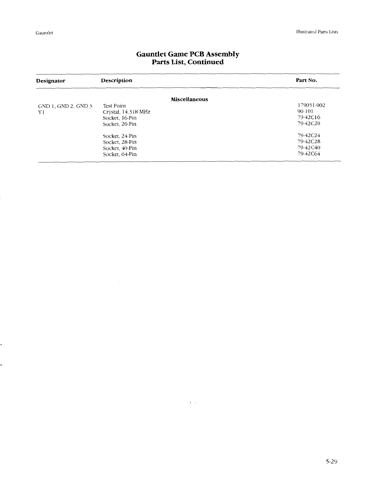
This page is a drawing, shown as the original scan.
Gauntlet IMustrated Parts Lists
NOTICE TO ALL PERSONS RECEIVING THIS DRAWING
CONFIDENTIAL: Reproduction forbidden wathout the speciic written permission of Alani Games Corporation, Sunnyvale, CA. This drawing is only Conditionally issied, and nether recoypl nor Dossession thereat pin, oF license to subject matter of the drawing OF any design o echnical informaton shown thereon, nora "ng oF any part Except for manufacture by vendors of Alan Games Corporation, and for manufacture ‘corporation's wniten license, no nght 's granted to reproduce ths drawing ‘or the subject matter thereot, uniess by wnitien agreement with or writen permission from the corporation
Qi Q2 °
eoCeH] ca Lece2 CRB 5 ° e ai }e
o__} ens q| ° O eL_sers|"}o Se r.) O of _fecr csoo{_}o,, of }9 @ O orn: RO ,__}eceef + tpaz030) TDAZOZ0 O
cé
J I JCDL J cR4
J15V
& E <n 8. ue ge 2S <3 D< wn vo z
5-30
Gauntlet Illustrated Parts Lists Audio PCB Assembly Parts List
Designator Description
| C1-C4 | Capacitor, Electrolytic, 3300 uf, 25 V | 123003-338 | |
| C5, C6 | Capacitor, Electrolytic, 100 pf, 25 V | 24-250107 | |
| C7-C12 | Capacitor, Ceramic, .1 pf, 25 V | 122002-104 | |
| C13, C14 | Capacitor, Electrolytic, 22 uf, 35 V | 24-350226 | |
| C15-C18 | Capacitor, Ceramic, .22 uf, 25V | 122006-224 | |
| C19, C20 | Capacitor, Ceramic, .001 yf, 25 V | 122002-102 | |
| C21, C22 | Capacitor, Ceramic, .1 wf, 25 V | 122002-104 | |
| CR1-4 | Diode, 1N5401, 100 V, 3A | 31-1N5401 | |
| CR5-12 | Diode, 1N4001, 50 V | 31-1N4001 | |
| Jisv | Connector, Header, 9 Ckt., .156 Ctr. | 179213-009 | |
| JAUX | Connector, Header, 9 Ckt., .156 Ctr. | 179213-009 | |
| JCC-1, JOC-2 | Term, Fast-on Tab, .187 x .020 | 179051-001 | |
| JCDL | Term, Fast-on Tab, .187 x .020 | 179051-001 | |
| JSPK | Connector, Header, 6 Ckt., .156 Ctr. | 179213-006 | |
| QI, Q2 | Amplifer, TDA-2030 | 137301-001 | |
| RI | Resistor, Pot, 10k@, Dual | 119011-103 | |
| R3 | Resistor, 109, +5%, 4 W | 110000-100 | |
| R4-R7 | Resistor, 22 kQ, +5%, 4 W | 110000-223 | |
| R8, RP | Resistor, 10 kQ, +5%, 4 W | 110000-103 | |
| R10, R11 | Resistor, 1 kQ, +5%, 4 W | 110000-102 | |
| R12, R13 | Resistor, | 12, +5%, %4 W | 119000-010. |
| SW | Self-Test Switch, Slide, Miniature, SPDT | 66-004 |
Heat Sink, TO-220 178190-032 Screw, Pan-Head, Cross-Recessed, #6-32 x 3/8-Inch Long 72-16068 Nut/Washer Assy, #6-32 75-99516
Gauntlet
A043046-01 C ° . a a i=) 1 2 39 9 ee : ’ ao CCUe) les « o i & 5 i] ° : 4 & \ea ey a | ?fo
cf B300 ® HW G eo a is a Aas aaa RL aly: ry 2a2}s ete} {lo os Q aa OF C26 2 £ @ see 4 am eBoy ° Z2pe co Zo
t 88
22] cor on + a8 B BB0O a e BBOO it 23 a 9 AT{Z _
0 WW = A t =. 4 al 3] I : meee ye cio F ° ii} 3 H ofp 3 8 2} {*
¥ A0dgQa6 : = a COCOOTOCO} sw 2 aw” (196% 03 R28 R26 Alustrated Parts Lists
NOTICE TO ALL PERSONS RECEIVING THIS DRAWING
CONFIDENTIAL; Reproduction forbiciden without the spectic writen permission ot tani Games Corporation, Sunnyvale, CA. This drawing is only conditionally issued, an Ticense to use, Ihe subject matter of the drawing, 0 any design oF techni reproduce this drawing or any part thereot, Excepi for manufacture by vendors of Alan! Ga ;poralion's written inense, no nght is granted to reproduce ths Grawing or the subject matter thereot, unless by watfen agreement wth or writen Permission from the corporation.
Figure 5-10 Regulator/Audio Ill Printed-Circuit Board Assembly
Gauntlet Illustrated Parts Lists
Regulator/Audio III Printed-Circuit Board Assembly Parts List
| Designator | Description | Part No. |
Capacitors
| cl | 22 pF, 35 V Electrolytic Capacitor | 24-350226 |
| c2 | 0.22 uF 25 V Ceramic Capacitor | 122004-224 |
| C3 | 0.001 pF, 50 V Ceramic Capacitor | 122002-102 |
| C4 | 0.1 wR, 50 V Ceramic Capacitor | 122002-104 |
| cs. | 22 uF, 35 V Electrolytic Capacitor | 24-350226 |
| co | 0.22 uF, 25 V Ceramic Capacitor | 122004-224 |
| C7 | 0.001 pF, 50 V Ceramic Capacitor | 122002-102 |
| C8 | 0.1 wE, 50 V Ceramic Capacitor | 122002-104 |
| ©9, C10 | 22 uF, 35 V Electrolytic Capacitor | 24350226 |
| Cll, C12 | 0.1 wE, 50 V Ceramic Capacitor | 122002-104 |
C13 3300 uF, 35 V Electrolytic Capacitor cl4 0.22 uF, 25 V Ceramic Capacitor
| C15 | 3300 wE, 35 V Electrolytic Capacitor | 24-350338 |
| C16 | 0.22 wE, 25 V Ceramic Capacitor | 122004-224 |
| C17, C18 | 0.1 FE, 50 V Ceramic Capacitor | 122002-104 |
| C19 | 1000 uF, 25 V Electrolytic Capacitor | 24-250108 |
| C20 | 0.1 pF, 50 V Ceramic Capacitor | 122002-104 |
| C21 | 22 uF, 35 V Electrolytic Capacitor | 24-350226 |
| C22 | 0.001 “EF, 50 V Ceramic Capacitor | 122002-102 |
| C23, C24 | 0.1 wE, 50 V Ceramic Capacitor | 122002-104 |
| C25-C27 | 3300 wE, 35 V Electrolytic Capacitor | 24-350338. |
| C28 | 470 pF, 25 V Electrolytic Capacitor | 24-250477 |
| C29, C30 | 0.1 pF, 50 V Ceramic Capacitor | 122002-104 |
Connectors
| Jo | 9-Position Header Connector | 179069-009 |
| aad | 12-Position Header Connector | 179069-012 |
| J8 | 9-Position Polarized Header Connector with .156-Inch Centers | 179213-009 |
Diodes
| CR1-CR3 | Type-1N4002 Diode | 31-1N4002 |
| CR4-CR7 | Type-1N5401 Rectifier Diode | 31-1N5401 |
| CRO | Type-1N4002 Diode | 31-1N4002 |
Resistors
| R3. | 12 kQ, +5%, '4 W Resistor | 110000-123 |
| R4, RS | 100 kQ, +5%, 4 W Resistor | 110000-104 |
| R7 | 12kQ, +5%, 4 W Resistor | 110000-123 |
| R8, RO | 100 kQ, £5%, 4 W Resistor | 110000-104 |
| R10, RII | 1kQ, +5%, % W Resistor | 110000-102 |
| R12, R13 | 100 kQ, £5%, 4 W Resistor | 110000-104 |
| R14, RIS | 10 kQ, +5%, 4 W Resistor | 110000-103 |
| R18 | 1000, +5%, 4 W Resistor | 110000-101 |
(Continued on next page)
ye aa oes
Gaunilet Mlustrated Parts Lists
Regulator/Audio III Printed-Circuit Board Assembly Parts List, continued
| Designator | Description | Part No. | |
| RD | 5.6kQ, +5%, 4% W Resistor | 110000-562 | |
| R20 | 2.79, 45%, 1 W Resistor | 110009-027 | |
| R21 | 272, +5%, 4 W Resistor | 110000-270 | |
| R22 | 1002, +5%, 4 W Resistor | 110000-101 | |
| R23 | 0.19, +5%, 5 W Resistor | 116007-001 | |
| R24 | 5.6k2, 45%, 4 W Resistor | 110000-562 | |
| R25-R27 | 0.19, +5%, 5 W Resistor | 4116007-001 | |
| R28. | 2.70, | 45%, % W Resistor | 110000-027 |
| R29 | 7.5kQ, +5%, 4 W Resistor | 110000-752 | |
| R31 | 3.9kQ, +5%, % W Resistor | 110000-392 | |
| R32 | 2.79, +5%, % W Resistor | 110000-027 | |
| R33, R34 | 22 kQ, +5%, 4 W Resistor | 110000-223 |
Transistors
| Q6 | TIP-32 Transistor | 33-TIP32 |
| Q7, Q8 | Type-2N3055 Transistor | 34-2N3055 |
Miscellaneous
| QI, Q2 | Type-TDA-2030 Amplifier | 137301-001 |
| Q@ | Type-7815, +15 V Regulator | 37-7815 |
| Q4 | Type-7915, - 15 V Regulator | 37-7915 |
| Qs | Type-LM305 Regulator | 37-LM305, |
| R30 | 1k Horizontal Potentiometer | 119002-102 |
| (Q4, Q6) | Thermal Insulator | 78-16014 |
| (Q7, Q8) | Thermally Conductive Insulator | 78-16008 |
RTV Silicon Rubber Sealing Compound 78-13003
Heat Sink 034531-01 ‘Test Point (Acceptable substitute is part no. 020670-01) 179051-002
5.34
Your Comments, Please!
Your comments will assist Atari Games Corporation in improving its publications. The comments are an important part of preparing for revisions of game manuals. Please write in the space below. No postage stamp is necessary if mailed in the U.S.A.
If you have any technical questions about certain ATARI games products, or are requesting additional technical publications, we will immediately forward your
Page: Comments:
Fill in if you wish a reply
Name
Firm C1 Distributor
Address CO Operator
City State Zip O Other
Gauntlet Ist printing
Area Code Phone
Tape This Edge
First Fold
No postage necessary if mailed in the United States <x
a
BUSINESS REPLY MAIL a
FIRST CLASS PERMIT NO. 173. MILPITAS, CA fe POSTAGE WILL BE PAID BY ADDRESSEE Pe Ce
Atari Games Corporation ee 737 Sycamore Drive Pe
Attn: Customer Service
P.O. Box 906 Pe Milpitas, California 95035
Second Fold
From.
Your Comments, Please!
Your comments will assist Atari Games Corporation in improving its publications. The comments are an important part of preparing for revisions of game manuals. Please write in the space below.
If you have any technical questions about certain ATARI games products, or are requesting additional technical publications, we will immediately forward your
Page: Comments:
Fill in if you wish a reply:
Name
Firm, O Distributor Address O Operator
City Country C Other
Gauntlet Ist printing
Phone: Country Code Local Number
Tape This Edge
First Fold
Attach Necessary Postage
Atari Games Corporation
Attn: Customer Service
Tipperary Town, Ireland
Second Fold
From:
Gauntlet’
Coin Information and Game Statistics
Date:
Plyr 0 Coins Number of coins deposited in Warrior coin mechanism Plyr 1 Coins Number of coins deposited in Valkyrie coin mechanism Plyr 2 Coins Number of coins deposited in Wizard coin mechanism Plyr 3 Coins Number of coins deposited in Elf coin mechanism 0 Plyr Mins Minutes of idle time 1 Plyr Mins Minutes played as a 1-player game 2 Plyr Mins Minutes played as a 2-player game 3 Plyr Mins Minutes played as a 3-player game 4 Plyr Mins Minutes played as a 4-player game Total Games Total number of unique games played* Error Count EEROM errors
Total Coins Total number of coins deposited in all four mechanisms Avg. Time/Coin Average game time per coin in seconds
Histogram Information 0 1 2 3 Seconds Warrior Valkyrie Wizard Elf
0-29 30-44 45-59
60-74 75-89 90-104 105-119
120-134 135-149 150-164 165-179
180-194 195-209 210-224 225-239
240-254 255-269 270-284 285-299 300 & up.
*One game" is the time between leaving the Attract Mode and returning to it, regardless of time, number of coins inserted, or how many have played Gauntlet. The games are measured since the last time the statistics were cleared.
Hate
Warranty
Seller warrants that its printed-circuit boards and parts thereon are free from defects in material and workmanship under normal use and service for a period of ninety (90) days from date of shipment. Seller warrants that its video displays and LaserVideo disc players (in games supplied with displays and video-disc players) are free from defects in material and workmanship under normal use and service for a period of thirty (30) days from date of shipment. None of the Seller’s other products or parts thereof are warranted. If the products described in this manual fail to conform to this warranty, Seller's sole liability shall be, at its option, to repair, replace, or credit Buyer's account for such products which are returned to Seller during said warranty period, provided:
- Seller is promptly notified in writing upon discovery by Buyer that said products are defective;
- Such products are returned prepaid to Seller's plant; and
- Seller's examination of said products discloses to Seller's satisfaction that such alleged defects existed and were not caused by accident, misuse, neglect, alteration, improper repair, installation, or improper testing. In no event shall Seller,be liable for loss of profits, loss of use, incidental or consequential damages. Except for any express warranty set forth in a written contract between Seller and Buyer which contract supersedes thé terms herein, this warranty is expressed in lieu of all other warranties expressed or implied, including the implied warranties of merchantability and fitness for a particular purpose, and of all other obligations or liabilities on the Seller's part, and it neither assumes nor authorizes any other person to assume for the Seller any other liabilities in connection with the sale of products by Seller.
The use of any non-Atari parts may void your warranty, according to the terms of the warranty. The use of any non-Atari parts may also adversely affect the safety of your game and cause injury to you and others. Be very cautious in using non-Atari-supplied components with our games, in order to ensure your safety. Atari distributors are independent, being privately owned and operated. In their judgment they may sell parts or accessories other than Atari parts or accessories. Atari Games Corporation cannot be responsible for the quality, suitability or safety of any non-Atari part or any modification including labor which is performed by such distributor.
Atari Games Corporation P.O. Box 361110 Milpitas, California 95035 AF