Artic Thunder 39in
Arctic Thunder (v1.002) (Midway Games, 2001) · Manual · 114 pages · 29 sections · original scan
NOVEMBER 2000 G/DMIDWAY eg
Game Operations Manual for 39” Dedicated Video Game
Manual Includes
Operation & Adjustments Parts Information * Wiring Diagrams * Testing & Problem Diagnosis
The manufacturer intends that this game is to be operated for amusement purposes only and not in contravention of any federal, state or local law or regulation of the United States or any foreign country governing gaming devices. All operators of this game are responsible for its operation in accordance with such laws and regulations. The manufacturer's factory settings for this game may require adjustment in order to comply with laws applicable in an operator's specific jurisdiction. It is the operator's responsibility to determine whether adjustments are necessary and, if they are, to make the appropriate adjustments prior to operating the amusement game.
MIDWAY AMUSEMENT GAMES, LLC 3401 NORTH CALIFORNIA AVENUE CHICAGO, ILLINOIS 60618 USA http://www.midway.com
This page carries no recoverable text. It is a drawing or a photograph. See the original scan.
This page carries no recoverable text. It is a drawing or a photograph. See the original scan.
This page carries no recoverable text. It is a drawing or a photograph. See the original scan.
CABINET LINKING INSTRUCTIONS
CF To link two cabinets, use the crossover coupler included in the spare parts bag. Connect the factory installed linking cable to the coupler and follow the instructions for “Wiring Modifications and Software Setup” located below starting with step #7.
To link three or more cabinets, use a standard 10 base-T ethernet hub and follow all of the instructions for “Wiring Modifications and Software Setup” located below.
CABINET ARRAYS To create a Video Game Machine (VGM) Array, join the cabinets together. Each VGM comes equipped with the necessary hardware to connect cabinets and provide maximum stability. Hardware is located in the spare parts bag inside the cash box.
To join cabinets, remove the flat-head carriage bolts from the top and rear of adjacent cabinet sides. Position cabinets next to one another and adjust the leg levelers until all holes are aligned. Insert long carriage bolts through the holes in both cabinets, and then fasten in place with the nuts provided.
NETWORK CONSIDERATIONS Each VGM comes complete with a factory installed network cable. Optionally, a hub can be installed and located remotely to monitor network activity. Cables up to 328 ft., or 100 meters, in length may be used in conjunction with the hub provided they are Category 3 or higher, 100 ohm unshielded twisted pair communications grade wiring. Standard telephone cables are not sufficient for this application and should not be used.
Take care to protect exposed wiring from player foot traffic, cleaning crews, service personnel, etc. Use approved conduit or wire channels to support cables. Please note that modular connectors do not have strain relief.
Prevent linking cables from becoming damaged by avoiding sources of extreme heat or moisture, and high amounts of electrical energy like neon signs, fluorescent fixtures, two-way radios, cordless phones, power circuits, public address system wiring, etc.
Universal RJ-45 modular plugs are not numbered or coded in any way. Clearly label all network connections to avoid confusing network cables with computer or telephone circuits.
WIRING MODIFICATIONS AND SOFTWARE SETUP
- Place the linking hub inside the base of a cabinet nearest the center of the array. Remember that the crossover couplers supplied with the game are not used when creating an array using the hub. Crossover couplers are only used to link two cabinets.
- Unlock and remove the rear door from the cabinets selected to be part of the array. Inside the cabinet you will find a coil of linking cable with one end already attached to game electronics. Uncoil just enough of the cable to reach the hub, then recoil the rest of the cable and tie it in place. Repeat this procedure for each of the other cabinets. Do not reinstall the cabinet door(s) at this time.
- Route the free end of each cable out through the notch located in the rear door opening and plug into any jack on the rear panel of the linking hub. Route the free end of the AC adapter for the hub and plug it into the 9VAC jack on the front panel of the hub. Now all of the cables can be connected to the hub.
ARCTIC THUNDER v
Refer to the manufacturer's instructions in order to set the hub switches for LNK (link) and X (crossover) activity.
Fasten the hub to the bottom of the most central cabinet using a hook-and-loop type material. Orient the hub so that the indicator lights are visible and cable jacks are accessible.
Make sure excess cable is tied into a coil and that all cables are routed through the notch in the rear door. Connect the AC adapter for the hub and all line cords to AC power.
te CAUTION
Do not connect or disconnect any cable to the game electronics or hub with the power turned on. Circuit disruptions may damage the game and void the warranty.
Switch on power and closely observe the screen for each cabinet during start up. Each automatically enters ATTRACT MODE if no errors are found. Refer to Troubleshooting in the operation manual if errors are detected.
Verify software version compatibility for each game machine. Newer versions may contain instructions previous versions do not, causing games to halt or reset at random.
Unlock the coin door for each cabinet to access the operator control buttons inside coin vault. Press and hold the TEST button to enter the menu system. Select SYSTEM INFORMATION MENU at the Main Menu screen. Scroll to SOFTWARE VERSION and press the TEST button. Observe screen for desired information
Assign game machine a link number. Select ADJUSTMENTS from the Main Menu screen. Scroll to and select GAME LINK NUMBER by pressing the Test button. Assign a linking number ranging from 1 to 4 to each game cabinet.
. Repeat these steps for each remaining game cabinet you wish to link.
. Close and lock the coin door, and reinstall and lock the rear door for each cabinet. Lower the leg levelers for each cabinet until the casters do not touch the floor and the cabinets are level. Lock the levelers in position by tightening the nuts provided.
vi Mipway AMUSEMENT GAMES, LLC
|? vee) Cl uc ERG TrFAGsiGiD Ee Fe
OPERATIONS
CHAPTER 1 OPERATION
SAFETY INSTRUCTIONS The following safety instructions apply to operators and service personnel. Read these instructions before servicing or preparing the Video Game Machine (VGM) for play. Other safety instructions appear throughout this manual.
DEFINITIONS OF SAFETY TERMS + DANGER indicates an imminent hazard. If you fail to avoid this hazard, it WILL cause death or serious injury. + WARNING indicates a potential hazard. If you fail to avoid this hazard, it COULD cause death or serious injury. + CAUTION indicates a potential hazard. If you fail to avoid this hazard, it MAY cause minor or moderate injury. CAUTION also alerts you about unsafe practices. + NOTE indicates information of special importance.
MIDWAY AMUSEMENT GAMES, LLC
CHAPTER 1 OPERATION
The hard disk drive must be packed in an anti-static bag. When shipping the drive for repair or replacement, pack it in an approved container (P/N 08-8068). Do not stack or drop hard disk drives.
If you or anyone in your family has experienced symptoms linked to an epileptic condition (e.g., seizures or loss of awareness), immediately consult your physician before using any video games.
We recommend that parents observe their children while they play video games. If you or your child experience the following symptoms: dizziness, altered vision, eye or muscle twitching, involuntary movements, loss of awareness, disorientation, or convulsions, DISCONTINUE USE IMMEDIATELY and consult your physician.
CHAPTER 1 OPERATION
PRODUCT SPECIFICATIONS
Operating Requirements
Location Electrical Power Temperature Humidity
Domestic 120VAC @ 60Hz 4.0 Amps 32°F to 100°F Not to exceed 95% relative Foreign 230VAC @ 50Hz 2.0 Amps (0°C to 38°C) Japan 100VAC @ 50Hz 4.0 Amps
Cabinet Statistics
| Shipping Dimensions | Shipping Weight (Approx.) | Design Type |
| Width 40" (101.6 cm) | 600Lbs (272kg) Main Cabinet | Sit-On Dedicated Video Game |
| Depth 95" (241.3 cm) | 200Lbs (90kg) Control Cabinet | Machine with Steering Feedback |
Height 86" (218.4 cm) 125Lbs (57kg) Seat Assy.
Game Characteristics
| Player Variables | Operator Variables | Diagnostics |
| 1 to 4 players per VGM (with Linking) | Coinage, Play Mode, Difficulty, | Automatic Power-Up Self-Test |
| High Score Recognition | Volume, Audits, Statistics | Manual Multi-Level Menu System |
Suitable for All Ages (AAMA Certified)
Equipment Characteristics Video Display Monitor VGA Resolution 39” (99 cm) CRT
Audio System Digital Stereo 5” (12.7 cm) Coaxial Full Range Speakers
Currency Acceptors 2 Coin Mechanisms Dollar Bill Validator Ready Electronic Coin Acceptor Ready
PRODUCT CONFIGURATION
Stand Alone Video Game Machine Each VGN is ready to play right out of the box. Operators may use the menu screens in the game menu system to determine some player variables in advance or leave the choices up to the players.
Linked Video Game Machines Linking allows players to compete against each other on a single course. Operator menus are used the same way as in stand-alone VGMs. Crossover couplers and linking cables to connect two VGMs are factory installed. Use an optional 10 base-T ethernet hub to interconnect up to four VGMs.
4 MIDWAY AMUSEMENT GAMES, LLC.
CHAPTER 1 OPERATION
SET-UP 1. Remove all items from the shipping containers and set them aside. Remove all packing material. Inspect the exterior of the main cabinet, control cabinet and the seat pedestal for any damage.
Remove keys from controller assembly. Unlock and open the rear door, and the coin and cash boxes. Electrical cords, mechanical components, and assorted spare parts are packed inside the cash box. Casters and leg levelers for main cabinet, control cabinet, and pedestal are packed inside of a box with the seat pedestal
Install one nut onto each leg leveler. Tilt main cabinet as needed to locate threaded holes in the underside of cabinet. Install a leveler and nut into each hole. Do not tighten nuts at this time. Repeat these steps for the center control cabinet and seat pedestal as well.
Install provided swivel casters. Install six (6) swiveling casters on the center control cabinet and seat pedestal as shown in the illustration below.
Install provided locking casters. Install two (2) locking casters on seat pedestal as shown in the illustration below.
The main cabinet is mounted on casters. Roll the cabinet to its intended location, maintaining clearance between the cabinet and walls, drapes, other games or obstructions. Roll the control cabinet near the main cabinet, leaving enough space to attach wiring harness. Mate each cable from the control cabinet to main cabinet. Press firmly, but do not force, the keyed connectors until the contacts properly seat. Slide the control cabinet toward main cabinet between the mounting brackets, guiding the harness and cables into main cabinet.
LOCATION OF CASTERS AND LEVELERS
CHAPTER 1 OPERATION
Lower and adjust each leg leveler on the control cabinet until it is stable and level. Adjust the levelers until the bottoms of both pieces are flush and parallel with each other. Inspect for binding or pinched wires. Align bracket holes with mounting holes in base of control cabinet. Insert and firmly tighten fasteners to attach the two pieces together as a single unit.
Locate the pedestal assembly mounting rails and rubber bumper spacers, which are shipped along with hardware, inside a cash box.
Install rubber bumpers. Rubber bumpers are used to maintain a 3/16” space between the pedestal and cabinet assembly, and are essential in absorbing vibration. Insert one bumper using a twisting motion into each of the pre-drilled holes located along the bottom edge of control cabinet assembly.
. Install pedestal mounting rails. Orient the mounting rail so that the pre-attached rubber bumpers face outward, then insert rail. Fasten rail in place with the hardware provided. If necessary, refer to illustration for proper placement.
MOUNTING BRACKET LOCATION
- Roll the pedestal section near the cabinet, align the opening in the pedestal with the ends of the rails. Slide the pedestal forward onto extended mounting rails leaving enough space to attach the wiring harness. Mate each cable connector and press firmly to seat the contacts.
Ensure no wires are pinched during pedestal attachment. Attach pedestal assembly using 1/4-20 tamper resistant screws and large flat washers provided. A T27 wrench is included to tighten these screws firmly.
. Lower and adjust each leg leveler until the pedestal section is stable and level. Adjust the levelers until the bottoms of all pieces are flush and parallel with each other. Inspect for binding or pinched wires. Insert and firmly tighten the remaining fasteners to attach the two pieces together as a single unit.
MIDWAY AMUSEMENT GAMES, LLC.
CHAPTER 1 OPERATION
LOCATION OF PEDESTAL ASSEMBLY MOUNTING HOLES
- An extra padlock may be installed to secure the rear door. Locate hasp. Remove the two lock bracket nuts from inside the cabinet, above the rear door opening. Slide the hasp bracket onto the bolts so that it protrudes from the hole in back of the cabinet, then reinstall nuts.
- Modify the lock plate at the top of the rear door. Remove the bolts and nuts from the lock plate, then rotate the plate so that the slot will be above the door. Reinstall the bolts and nuts and tighten firmly.
- Reinstall the rear door onto the cabinet and close it. Lock the rear door and remove the key. If required, install the extra padlock through the hasp at this time. Install the screws at the top and sides of the rear door and tighten snugly. Leave the remaining doors open at this time.
TYPICAL REAR DOOR HASP INSTALLATION
CHAPTER 1 OPERATION
- The power cord is packed in with the spare parts. Insert a portion of the line cord in the cord clamp leaving enough slack for the cord. Match the holes on the IEC plug with the prongs in the receptacle and push firmly to seat the line cord.
LINE CORD INSTALLATION
- Plug the game into a grounded (3-terminal) AC wall outlet. Switch on power to the game using the ON/ OFF switch located on the upper left top of the cabinet (when viewed from the player’s position). The game will power up and begin its self test. If no errors are found, the game will automatically enter the attract mode of operation (scenes and sounds from typical races, player’s scores, messages, etc.).
- Open the coin door. Press and hold the Begin Test button on the operator control switch panel to enter the menu system. Wait until the Main Menu screen appears on the monitor.
TYPICAL COIN DOOR SWITCH LOCATION
- Follow on-screen instructions to select Diagnostics, then choose SWITCH TESTS. Follow the onscreen instructions to verify that each of the controls is operational. If no errors are found, the controls should function well.
- Return to the Diagnostics screen, then choose CONTROLLER TEST. Follow the on-screen instructions to verify the presence of steering resistance. If no errors are found, the aim will be good.
- Return to the Main Menu screen, and then choose EXIT. The game will automatically enter its “attract mode of operation (scenes and sounds from typical races, player’s scores, messages, etc.).
8 MIDWAY AMUSEMENT GAMES, LLC.
CHAPTER 1 OPERATION
- Insert currency or tokens and play a game. Change the volume and make any other adjustments. Close and lock all open doors. Tighten the leveler nuts and engage the caster locks.
MAINTENANCE + Viewing Glass It is not necessary to switch off power to the game to clean the glass. Apply a mild glass cleaner to a clean cloth or sponge and wipe the viewing glass.
Do not apply the cleaner directly on the glass! Liquid could drip down into switch or control circuits and cause erratic game operation.
+ Player Controls Use plastic-safe, non-abrasive cleaners to avoid damage. Apply cleaner to a clean cloth or sponge and wipe the player controls.
Do not apply the cleaner directly on the controls!
+ Cabinet and Seat Use plastic-safe, non-abrasive cleaners to avoid damage. Apply cleaner to a clean cloth or sponge and wipe the seat or cabinet.
Do not apply cleaner directly on artwork or cabinet!
GAME FEATURES Arctic Thunder™ ships configured for one-player game play. Up to four cabinets may be linked to promote player competition.
Arctic Thunder™, the action packed snowmobile tour for the new millennium, is a polar fantasy that transports adventurous trekkers across continents in search of unimaginable and ultra-realistic thrills and chills. From the snowy plateaus of the Himalayas and the Swiss Alps to snowscapes in Europe and the Americas, players can assume the role of Ponzo, the resident polar primate, or of Willie Qiunn a hip and cool Rastafari, but to name a few. Slaloming through fluffy white powder on the back of a snowmobile, players and their opponents vie for power-ups while launching shiver-worthy snowballs and frosty power attacks.
STARTING UP Each time power is switched on or restored to the game machine, the system enters Start-up Tests. The software revision level is shown at the top of the screen. A testing message will appear for approximate 60 seconds.
The system enters Attract Mode once it passes all power-up tests. The Attract Mode screen will cycle endlessly and display a variety of scenes and sounds from a typical race on any given track. The system does not exit Attract Mode until the desired amount of coins or tokens is inserted and game play commences.
CHAPTER 1 OPERATION
GAME RULES AND OBJECTIVES The game is configured for one-player game play, but up to four cabinets may be linked at one time to promote multiple player competition. To enter Game Mode, individual player(s) must insert the required amount of currency or tokens, press the Start button, and select a sled and track. The main objective of the game is to earn top ranking on a given track environment and/or against other drivers.
PLAYER CONTROLS + Start Button, located on the right-hand side of the handlebar, is used to begin game play or to select certain features before a race.
+ Attack Button, located on the left-hand side of handlebar is used during competition to punch opponents, launch snowballs, or power attacks.
+ Throttle Lever, located on the right-hand side of handlebar, is used to accelerate.
GAME OPERATION Access to the menu system for statistics, adjustments, and testing is secured by a keyed lock on the coin box to prevent tampering. When the menu system is entered, on screen messages guide the operator through tasks.
CABINET SWITCHES + ON/OFF SWITCH is located on the top right-hand side of cabinet.
+ REMOTE MONITOR ADJUSTMENTS knobs are located inside coin vault. Use the monitor test screens with these controls to adjust video image size, brightness, contrast, etc.
CONTROL BUTTONS + TEST BUTTON activates game Menu System. Press the Test button to access the Main Menu and select individual diagnostics, audits, utilities, etc.
+ VOLUME-UP BUTTON is used to move up through menu selections or adjustment items, as well as to increase volume level in game play.
+ VOLUME-DOWN BUTTON is used to move down through menu selections or adjustment items, as well as to decrease volume level in game play.
+ SERVICE CREDIT BUTTON is used to allot credits without affecting a game's bookkeeping total. This button is also used to exit a menu selection or return to the main menu.
10 Mibway AMUSEMENT GAMES, LLC
@ a” Om —,
CHAPTER :
& ©
ADJUSTMENT, DIAGNOSTIC &
AUDIT MENUS
CHAPTER 2 DIAGNOSTICS
ADJUSTMENT, DIAGNOSTIC & AUDIT MENUS
MENU SYSTEM
WHAT IS THE MENU SYSTEM? The game’s Menu System is a series of auditing, game adjustments and diagnostic screens. You can easily access and apply these screens to optimize game performance. For instance...
+ Use game audit screens to assess game performance. + Use adjustment screens to help you customize game performance. For example, you can restore factory default game settings. You can also calibrate player controls for player accuracy. + Use diagnostic screens to verify proper equipment operation.
ACCESSING THE MENU SYSTEM Open the coin door. Locate and press the TEST button. The game system will exit game Attract Mode and enter Diagnostic Mode. The Main Menu, which is the opening screen of the Menu System, will appear.
Game audits, adjustments and diagnostics are a few examples of line items you can expect to see in the Main Menu. Selecting a line item opens its submenu, and each submenu presents at least one option that you may act upon.
ARCTIC THUNDER MAIN MENU.
SYSTEM INFO AUDITS ADJUSTMENTS DIAGNOSTICS UTILITIES VOLUME LEVELS PRICING CALIBRATE FEEDBACK EXIT
TYPICAL MAIN MENU SCREEN
MENU LAYOUT Observe that each menu screen basically uses the same layout.
- The block at the top of each screen displays the current menu title. + Data, such as menu items and video reports, etc., appears in the center of the screen. + Messages, for example explanations and active control functions, etc., appear at the bottom of the screen.
MENU NAVIGATION TOOLS, Use the operator control buttons located inside the coin door to navigate menus. Press the Volume Up or Volume Down button to scroll through and select menu options.
Press the Test button to select the option highlighted and access the next menu level. NOTE: Only one highlighted option can be selected at a time.
To return to play mode from the Main Menu, select Exit and press the Test button. To return to the Main Menu or to play mode from a submenu, select Return to Previous Menu and press the Test button. Repeat as necessary until you return to desired screen or menu.
2 MIDWAY AMUSEMENT GAMES, LLC
CHAPTER 2 DIAGNOSTICS
Main Menu, continued System Information Menu
SYSTEM INFORMATION MENU To verify the game’s software version, reset information, or to clear reset information, select System Information Menu from the Main Menu, then press the Test button. Select and perform desired function.
SYSTEM INFORMATION MENU
SOFTWARE VERSION BACK TO PREVIOUS MENU
To return to Main Menu, select Back to Previous Menu and press the Test button.
Main Menu, continued System Information Menu Software Version
SOFTWARE VERSION To verify game software version, select System Version from the System Information Menu. Observe screen for desired information.
SOFTWARE VERSION
ARCTIC THUNDER/SNOW.EXE 1.0.0.0 ARCTIC THUNDER/DIAGDLL.DLL 1.0.0.0 ARCTIC THUNDER/GOBJ.DLL 1.0.0.0 ARCTIC THUNDER/GOOSE.DLL 1.0.0.0 DIAGNOSTICS/DIAG.EXE 1.0.0.0 WINCSM/WINCSM.EXE 1.0.0.0 WINCSM/MAGICBUS.DLL 1.0.0.0
To return to the submenu, press the Test button; to return to the Main Menu select Back To Previous Menu and press the Test button.
Main Menu, continued Audits Menu
AUDITS MENU To view a game’s play statistics, select Audits Menu from the Main Menu, then press the Test button. Use the Volume buttons to scroll to desired audit item, then press the Test button. Follow on-screen instructions where necessary.
The left-hand side of an audit table displays the name of the audit item; the right-hand side shows the amount of play for that item as either a percentage, an average, or as elapsed time. Please note, record these statistics prior to performing any service or repairs.
CHAPTER 2 DIAGNOSTICS
Audits Menu, continued
AUDITS MENU
To return to submenu while viewing an audit table, press the Test button; to return to the Main Menu select Back To Previous Menu and press the Test button.
General Game Audits
GENERAL GAME AUDITS To view game audits, press the Volume Up or Volume Down button to select General Game Audits from the Audits Menu, then press the Test button. Observe screen for desired information.
GENERAL GAME AUDITS
4 Mipway AMUSEMENT GAMES, LLC
CHAPTER 2 DIAGNOSTICS
General Game Audits, continued
To reset audit table, select Clear located at the bottom of screen, then press the Test button. To leave table as it is, select Return located at the bottom of screen, then press the Test button. Please note, be sure to record any values prior to clearing table.
To return to the submenu, press the Test button; to return to the Main Menu select Return and press the Test button.
Washington, D.C. Audits (All track audits)
WASHINGTON, D.C. AUDITS To observe the audits screen for any one of the featured tracks, use the Volume Up or Volume Down button to select the desired audit, then press the Test button.
Observe screen for desired information. Please note, each sled track listed in the Audit Menu contains information identical to information shown in the table below.
To reset audit table, select Clear located at the bottom of screen, then press the Test button. To leave table as it is, select Return located at the bottom of screen, then press the Test button. Please note, be sure to record any values prior to clearing table.
ARCTIC THUNDER: WASHINGTON, DC.
To return to the submenu, press the Test button; to return to the Main Menu select Return and press the Test button.
CHAPTER 2 DIAGNOSTICS
Coin Audits
COIN AUDITS To view coin audits use the Volume Up or Volume Down button to select Coin Audits from the Audits Menu, then press the Test button. Observe screen for desired information.
To reset audit table, select Clear located at the bottom of screen, then press the Test button. To leave table as it is, select Return located at the bottom of screen, then press the Test button. Please note, be sure to record any values prior to clearing table.
COIN AUDITS
To return to the submenu, press the Test button; to return to the Main Menu select Return and press the Test button.
Credit Audits |
CREDIT AUDITS To view credit audits use the Volume Up or Volume Down button to select Credit Audits from the Audits Menu, then press the Test button. Observe screen for desired information.
To reset audit table, select Clear located at the bottom of screen, then press the Test button. To leave table as it is, select Return located at the bottom of screen, then press the Test button. Please note, be sure to record any values prior to clearing table.
CREDIT AUDITS
To return to the submenu, press the Test button; to return to the Main Menu select Return and press the Test button.
o Mipway AMUSEMENT GAMES, LLC
CHAPTER 2 DIAGNOSTICS
System Audits
SYSTEM AUDITS To view system audits, use the Volume Up or Volume Down button to select System Audits from the Audits Menu, then press the Test button. Observe screen for desired information.
To reset audit table, select Clear located at the bottom of screen, then press the Test button. NOTE: Be sure to record any values prior to clearing table. To leave table as it is, select Return located at the bottom of screen, then press the Test button.
SYSTEM AUDITS
To return to the submenu, select Return and press the Test button; to return to the Main Menu scroll to Return and press the Test button.
Watchdog Audits
WATCHDOG AUDITS To either view or clear information about the watchdog use the Volume Up or Volume Down button to select Watchdog Audits from the Audits Menu, then press the Test button. Observe screen for desired information.
To reset audit table, select Clear located at the bottom of screen, then press the Test button. NOTE: Be sure to record any values prior to clearing table. To leave table as it is, select Return located at the bottom of screen, then press the Test button.
WATCHDOG AUDITS
To return to the submenu, select Return and press the Test button; to return to the Main Menu scroll to Return and press the Test button.
CHAPTER 2 DIAGNOSTICS
Clear All Audits
CLEAR ALL AUDITS To clear all game audits use the Volume Up or Volume Down button to select Clear All Audits from the Audits Menu, then press the Test button.
Use the Volume buttons to select desired answer, then press the Test button. Observe a confirmation box appears on-screen to verify a selection was made.
CLEAR ALL AUDITS
To return to the submenu, select Return and press the Test button; to return to the Main Menu scroll to Back To Previous Menu and press the Test button.
Adjustments Menu
ADJUSTMENTS MENU To optimize game performance and earnings or to change the look or sound of the game, use the Volume Up or Volume Down button to select Adjustment Menu from the Main Menu, then press the Test button.
The Adjustments Menu enables customization of Attract Mode, fan and seat shaker intensity, game difficulty, as well as a whole host of other features. Please note, individual Game Adjustments are explained in more detail on the following pages.
To select a menu option in Adjustments use the Volume buttons to select it, then press the Test button.
ADJUSTMENT MENU
8 Mibway AMUSEMENT GAMES, LLC
CHAPTER 2 DIAGNOSTICS
Adjustments Menu, continued
Many line items in the Adjustments Menu provide multiple setting choices, a few of which are followed by a confirmation box as shown below to verify your selection prior to completing the request.
Be sure to read each option carefully, use the Volume buttons to select YES or NO, then press the Test button to lock in the setting. Selecting NO cancels any changed values and returns the previous values to memory.
ARE YOU SURE YOU WANT TO SELECT THIS SETTING?
TYPICAL CONFIRMATION BOX
Game Link Number
GAME LINK NUMBER Allows the game link number to be set. The setting range is: -Maximum: 4 -Minimum: 1 -Factory Setting: 1
Minimum Game Volume
MINIMUM GAME VOLUME Selects the minimum allowable setting for volume. The setting range for this adjustment is: -Minimum: ie) -Maximum: 255 -Factory Setting: 20
CHAPTER 2 DIAGNOSTICS
Main Menu Adjustments Menu Game Difficulty
GAME DIFFICULTY Determines level of difficulty during game play. The setting range is: -Easiest -Easy -Normal -Hard -Hardest -No Change -Factory Setting: Normal
Main Menu
Adjustments Menu Single First Free Game
SINGLE FIRST FREE GAME Enables the single play “free game for first place” option. The setting choices are: -Enable (Award free game) -Disable -No Change -Factory Setting: Enable
Main Menu
Adjustments Menu Linked First Free Game
LINKED FIRST GAME FREE Awards free game to top player in a 2, 3, 4 or more player race. The setting choices are: -Off (Does not award a free game in linked games) -Must Beat All Drones (In a game with one or more linked players, a free game is only awarded if each of the drones and linked players lose) -Two Players (In a game with at least two linked players, a free game is only awarded if the other linked player loses) -Three Players (In a game with at least three linked players, a free game is only awarded if the other linked players lose) -Four Players (In a game with at least four linked players, a free game is only awarded if the other linked players lose) -No Change -Factory Setting: Off
MIDWAY AMUSEMENT GAMES, LLC
CHAPTER 2 DIAGNOSTICS
Game Start Time
GAME START TIME Adjusts the game start time. The setting choices are: -Minimum: 45 -Maximum: 90 -Factory Setting: 55
Initials Entry
INITIALS ENTRY Enables players to enter their initials upon earning a high score, and displays high scores during attract mode. The setting range is: -Enable -Disable -No Change -Factory Setting: Disable
Fan Intensity
FAN INTENSITY Determines fan speed during game play. The setting range is: -Easy -Medium -Hard -Off -No Change -Factory Setting: Medium
Shaker Intensity
SHAKER INTENSITY Determines shaker rate during game play. The setting range is: -Easy -Medium -Hard -Off -No Change -Factory Setting: Medium
CHAPTER 2 DIAGNOSTICS
Tail Light
TAIL LIGHT Enables tail light illumination. The setting choices are: -Enable -Disable -No Change -Factory Setting: Enable
Wheel Strength
WHEEL STRENGTH Selects degree of wheel strength to be used for racing. The setting range is: -Very Light -Light -Normal -Heavy -Very Heavy -No change -Factory Setting: Very Heavy
Family Mode
FAMILY MODE Changes appearance of female character seen on logo screen. The setting range is: -Disable (Lewd appearance) -Enable (Conservative appearance) -No change -Factory Setting: Disable
Restore Factory Adjustments
RESTORE FACTORY ADJUSTMENTS Allows operator to restore all game settings to the original factory default settings. The setting range is: -Yes -No -Factory Setting: No
12 Mipway AMUSEMENT GAMES, LLC
CHAPTER 2 DIAGNOSTICS
Diagnostics Menu
DIAGNOSTIC MENU To verify condition of the electrical and electronic hardware in the game use the Volume Up or Volume Down button to select Diagnostics Menu from the Main Menu, then press the Test button.
Diagnostic tests assist in checking and adjusting the game’s major systems. It is important to periodically run diagnostics to improve and maintain game performance and player satisfaction.
DIAGNOSTICS MENU
Use the Volume buttons to select desired Diagnostic Menu option, then press Test button to enter.
To return to the Main Menu select Back To Previous Menu and press the Test button.
Monitor Setup
MONITOR SET-UP To verify color clarity of the monitor use the Volume Up or Volume Down button to select Monitor Setup at the Diagnostic Menu, then press the Test button.
Within the Monitor Set-up menu use the Volume buttons to select desired monitor setting, then press the Test button. Observe screen displays desired information and then automatically returns to the Monitor Set-Up Menu.
MONITOR SET-UP
CHAPTER 2 DIAGNOSTICS
Main Menu
Diagnostic Menu, continued Monitor Setup, continued
COLOR BARS. Observe 4 color bars in different shades appear on-screen as aids in adjusting the green, blue, and red color levels. Each color should appear sharp and clear. Check video brightness and contrast.
The CROSSHATCH PATTERNS test fills the screen with a series of dots within a grid. Observe the dots are perfectly round and that both the grid and dots are clear. Inspect monitor convergence, linearity, and screen size.
The single color screens, RED SCREEN, BLUE SCREEN, GREEN SCREEN, etc., fill the screen with a single color to be observed for complete saturation and clarity.
If any of the tests show a need for CRT adjustment, use the proper knobs on the Monitor Controls board.
To return to the submenu, select Return and press the Test button; to return to the Main Menu scroll to Back To Previous Menu and press the Test button.
Main Menu
Diagnostic Menu, continued Switch Tests
SWITCH TESTS To verify proper operation of game switch and button inputs use the Volume Up or Volume Down button to select Switch Test at the Diagnostic Menu, then press the Test button.
SWITCH TESTS
WHEEL: XXX GAS: = XXX START ATTACK
CREDIT VOL- VOL+ TEST LCOIN
RCOIN CCOIN ECOIN BILL
PRESS VOLUME - AND + TO EXIT
Press any switch on the control panel or coin door to cause the corresponding indicator on the screen to illuminate. Each illuminated square represents one completed switch circuit.
Press both Volume buttons simultaneously to return to the submenu; to return to the Main Menu scroll to Back To Previous Menu and press the Test button.
14 MIDWAY AMUSEMENT GAMES, LLC
CHAPTER 2 DIAGNOSTICS
DIP Switch Test
DIP SWITCH TEST To verify proper DIP switch setting use the Volume Up or Volume Down button to select DIP Switch Test at the Diagnostic Menu, then press the Test button.
The current settings will appear on-screen. The default switch position for switch one through 8 is OFF for standard operation. For information about DIP Switch settings refer to Chapter 5: Wiring.
DIP SWITCH TEST
S2 DIP SWITCH SCREEN
Linking Test
LINKING TEST To verify communications between a game machine and others linked to it use the Volume Up or Volume Down button to select Linking Test at the Diagnostic Menu, then press the Test button.
LINKING TEST
This diagnostic runs automatically and will display results on-screen.
To return to the submenu, select Return to Previous Menu and press the Test button; to return to the Main Menu scroll to Back To Previous Menu and press the Test button.
CHAPTER 2 DIAGNOSTICS
Main Menu Diagnostic Menu, continued Controller Test
CONTROLLER TEST To verify the proper directional movement of the controller assembly use the Volume Up or Volume Down button to select Controller Test at the Diagnostic Menu, then press the Test button.
Please note, avoid contact with controller assembly when conducting any of the controller tests because the controller automatically turns on its own.
Use the Volume buttons to select desired controller test option, then press Test button to enter.
CONTROLLER TEST
CALIBRATE FEEDBACK CONTROLLER CENTER CONTROLLER LEFT CONTROLLER RIGHT CONTROLLER INFO BURN-IN TEST. RETURN TO PREVIOUS MENU
Observe and follow the on-screen instructions when conducting a test. A message will appear on-screen to indicate a completed test. Press the Test or Start button to exit test once this message appears.
CALIBRATE FEEDBACK performs a complete calibration sequence which turns the controller to the left, center, and to the right at a variety of speeds. This is the most complete test for the controller.
The CONTROLLER CENTER, CONTROLLER LEFT, AND CONTROLLER RIGHT are individual controller tests and will perform only the test specified by the name.
The CONTROLLER INFO test does not automatically turn the controller and requires operator input to complete the test.
BURN-IN TEST performs the same tests as the Calibrate Feedback option, except it does so in a complete, uninterrupted cycle. To exit this test mode the game machine must be powered off.
Main Menu Diagnostic Menu, continued Seat Shaker Test
SEAT SHAKER TEST To verify the proper functionality of the shaker assembly use the Volume Up or Volume Down button to select Seat Shaker Test at the Diagnostic Menu, then press the Test button.
Use the Volume buttons to select desired shaker test, then press the Test button. Please note, the seat shaker is immediately and automatically engaged once the Test button is pressed.
16 MiDway AMUSEMENT GAMES, LLC
CHAPTER 2 DIAGNOSTICS
Main Menu
Diagnostic Menu, continued Seat Shaker Test, continued
SEAT SHAKER TEST
SHAKER ON BURN-IN RETURN
The SHAKER ON test performs a complete shaker vibration sequence at a variety of speeds. This is the most complete test for the seat shaker. Observe seat vibration.
The BURN-IN TEST performs the same tests as the Shaker On option, except it does so in a complete, uninterrupted cycle. To exit this test mode the game machine must be powered off. Observe seat vibration.
To end seat shaker test, press the Test button. To return to the submenu, select Return and press the Test button; to return to the Main Menu scroll to Back To Previous Menu and press the Test button.
Main Menu
Diagnostic Menu, continued Blower Test
BLOWER TEST To verify the proper functionality of the fan assembly use the Volume Up or Volume Down button to select Blower Test at the Diagnostic Menu, then press the Test button.
Use the Volume buttons to select desired blower test, then press the Test button. The fan blower is immediately and automatically engaged once the Test button is pressed.
BLOWER TEST
BLOWER ON BURN-IN RETURN
BLOWER ON performs a complete blower sequence at a variety of speeds. This is the most complete test of the blower. Observe breeze emitted from fan blower located in the center of the back-lit marquee.
BURN-IN TEST performs the same tests as the Blower On test option, except it does so in a complete, uninterrupted cycle. To exit this test mode the game machine must be powered off. Observe breeze emitted from fan blower located in the center of the back-lit marquee.
To end fan blower test, press the Test button. To return to the submenu, select Return and press the Test button; to return to the Main Menu scroll to Back To Previous Menu and press the Test button.
CHAPTER 2 DIAGNOSTICS
Lamp Test
LAMP TEST To detect intermittent or faulty incandescent bulbs use the Volume Up or Volume Down button to select LAMP TEST at the Diagnostic Menu. This test ensures that the incandescent bulbs critical to game operation function properly.
LAMP TEST
Use the Volume Up or Volume Down button to select desired Lamp Test and press the Test button. During the test observe the Lamp(s) turn ON according to the option selected.
To return to the submenu, select Return and press the Test button; to return to the Main Menu scroll to Back To Previous Menu and press the Test button.
Speaker Test
SPEAKER TEST To verify the proper functionality of the speaker assemblies use the Volume Up or Volume Down button to select Speaker Test at the Diagnostic Menu, then press the Test button.
SPEAKER TEST
RIGHT CHANNEL. Tests the functionality of the speaker located on the right-hand side of the game cabinet by emitting an audible voicing of the word “right.”
LEFT CHANNEL. Tests the functionality of the speaker located on the left-hand side of the game cabinet by emitting an audible voicing of the word “left.”
The 1KHz and 100Hz Sound tests are audible tones emitted from both speakers on the game cabinet.
Play Tune test option emits audible music from the game using both speakers on the game cabinet.
18 Mibway AMUSEMENT GAMES, LLC
CHAPTER 2 DIAGNOSTICS
Main Menu
Diagnostic Menu, continued Burn-in Tests
BURN-IN TESTS To properly diagnose intermittent problems with linking, steering, speakers, lamps, the seat shaker, or blower use the Volume Up or Volume Down button to select Burn-In Test at the Diagnostic Menu, then press the Test button. Select the desired test from the Burn-In Test menu.
A Burn-in test cycles non-stop through while diagnosing a problem. If an error is detected the Burn-In Test will stop and an error message will display on-screen.
Inputs from the control buttons are ignored during Burn-In. The Burn-In Test cannot be halted from the menus. To halt the test, switch off power to the game machine and then reboot game machine.
Main Menu
Diagnostic Menu, continued Verify Software
VERIFY SOFTWARE To perform software verification use the Volume Up or Volume Down button to select Verify Software at the Diagnostic Menu, then press the Test button.
The test diagnostic will automatically check the software in the span of a few minutes and then report the outcome as pass or fail. Observe screen for test results.
To return to the submenu, press any button; to return to the Main Menu scroll to Back To Previous Menu and press the Test button.
Main Menu
Utilities
UTILITIES To make adjustments to a variety of bookkeeping memory banks use the Volume Up or Volume Down button to select Utilities from the Main Menu, then press the Test button.
To select desired Utilities option use the Volume Up or Volume Down button, then press the Test button.
UTILITIES
RESET GAME TABLES FREE PLAY FULL FACTORY RESTORE SOFTWARE UPDATE COPY CMOS TO FLOPPY DISK CHECK DISK BACK TO PREVIOUS MENU
CHAPTER 2 DIAGNOSTICS
Main Menu
Utilities, continued
Several options under Utilities offer multiple setting choices in which you must select a value. Use the Volume buttons to change the value setting and observe a confirmation box as shown appears.
ARE YOU SURE YOU WANT TO RESTORE DEFAULTS?
YES NO.
TYPICAL CONFIRMATION BOX
Press the Volume Up or Volume Down button to select YES or NO, then press the Test button to lock in the setting. Selecting NO cancels any changed values and returns the previous values to memory.
To return to the Main Menu select Back To Previous Menu and press the Test button.
Main Menu
Utilities, continued Reset Game Tables
RESET GAME TABLES To reset game data --for example high scores-- use the Volume Up or Volume Down button to select Reset Game Tables at the Utilities screen, then press the Test button.
Use the Volume buttons to select desired function, then press the Test button.
To return to the submenu, select Return and press the Test button; to return to the Main Menu scroll to Back To Previous Menu and press the Test button.
Main Menu
Utilities, continued Free Play
FREE PLAY To adjust free play --which does not require credits or tokens for game play-- use the Volume Up or Volume Down button to select Free Play at the Utilities screen. Use the Volume buttons to select desired function, then press the Test button. The setting range is:
-Disable -Enable -No change -Factory Setting: Disable
To return to the Main Menu scroll to Back To Previous Menu and press the Test button.
20 MiDway AMUSEMENT GAMES, LLC
CHAPTER 2 DIAGNOSTICS
Full Factory Restore
FULL FACTORY RESTORE To return all game variables to the original factory setting use the Volume Up or Volume Down button to select Full Factory Restore from the Utilities screen, then press the Test button.
Use the Volume Up or Volume Down button to select desired answer, then press the Test button to complete selection. Observe a confirmation box appears on-screen to verify a selection was made.
FULL FACTORY RESTORE
To return to the submenu, select Return and press the Test button; to return to the Main Menu scroll to Back To Previous Menu and press the Test button.
Software Update
SOFTWARE UPDATE To aid installation of software use the Volume Up or Volume Down button to select Software Update at the Utilities screen, then press the Test button.
This option aids the process of either updating game software to the latest version or reverting to the previous version, if desired. Please note
SOFTWARE UPDATE
Either Software Update option offers multiple setting choices in which you must select a value. Use the Volume buttons to change the value setting and observe a confirmation box as shown on the next page appears.
CHAPTER 2 DIAGNOSTICS
Software Update
ARE YOU SURE YOU WANT TO UPDATE SOFTWARE?
Press the Volume Up or Volume Down button to select YES or NO, then press the Test button to lock in the setting. Selecting NO cancels any changed values and returns the previous values to memory.
Follow on-screen instructions to complete version selection. Please note, software update option exits the game Diagnostic menus.
Copy CMOS To Floppy Disk
COPY CMOS TO FLOPPY DISK To copy the system CMOS file onto a floppy disk use the Volume Up or Volume Down button to select Copy CMOS To Floppy Disk at the Utilities screen, then press the Test button.
Follow on-screen instructions to complete selection. To return to the Main Menu scroll to Back To Previous Menu and press the Test button.
Check Disk
CHECK DISK To check integrity of the disk use the Volume Up or Volume Down button to select Check Disk at the Utilities screen, then press the Test button to enter.
Follow on-screen instructions to complete selection. Please note, this option will cause the game machine to reboot.
22 Mipway AMUSEMENT GAMES, LLC
CHAPTER 2 DIAGNOSTICS
Main Menu
Volume Levels
VOLUME LEVELS To select a desirable volume level use the Volume Up or Volume Down button to select Volume Level from the Main Menu, then press the Test button.
Remember that the minimum sound level is set by using the Adjustments Menu.
VOLUME LEVELS
GAME MODE LEVEL. ATTRACT MODE LEVEL. BACK TO PREVIOUS MENU
Press the Volume Up button to increase sound level or the Volume Down button to decrease the sound level of the game. Press the Test button to lock the volume level at the selected value.
To return to the submenu, select Return and press the Test button; to return to the Main Menu scroll to Back To Previous Menu and press the Test button.
Main Menu
Pricing
PRICING Use Pricing to specify pricing settings other than the ones listed in the Pricing Table, to select the amount of credits required to start a game, and the amount of credits required to continue a game. Use the Volume Up or Volume Down button to select Pricing from the Main Menu, then press the Test button.
PRICING
SHOW CURRENT PRICING SELECT A PRICE CUSTOM PRICING BACK TO PREVIOUS MENU
Use the Volume Up or Volume Down button to select desired selection, then press the Test button.
To return to the submenu, select Return and press the Test button; to return to the Main Menu scroll to Back To Previous Menu and press the Test button.
CHAPTER 2 DIAGNOSTICS
Show Current Pricing
SHOW CURRENT PRICING Use the Show Current Pricing option to view the pricing options currently selected for game play. Remember pricing is used to select the amount of credits required to start a game, as well as to continue a game.
Press the Test button to return to main pricing menu; to return to the Main Menu scroll to Back To Previous Menu and press the Test button.
Select a Price
SELECT A PRICE MENU Use the Select a Price Menu to select preset price settings on a continental, or country by country basis, as outlined in the Pricing Table that follows.
Pricing can also be used to select the amount of credits required to start a game and the amount of credits required to continue a game.
Use the Volume buttons to select country, then press the Test button. Use the Volume buttons to further navigate selections listed within a desired country. Press the Test button to save selection.
CONTINENTAL PRICING TABLE
To return to the submenu, select Return and press the Test button; to return to the Main Menu scroll to Back To Previous Menu and press the Test button.
24 Mibway AMUSEMENT GAMES, LLC
CHAPTER 2 DIAGNOSTICS
Pricing Table
Use the Pricing Table illustrated below as a guide to select and/or verify the desired coin credit setting(s).
| NAME | START | |CONTINUE | |CREDITS/COIN | COIN1 | |COIN2 | |COIN3 | |COIN4 | /|BILL |
| ANTILLES | 2 | 2 | 1/25¢, 4/1G | .25¢ | 1G | |||
| AUSTRALIA 1 | 2 | E- | 1/3X20¢, 2/$1.00 | 20¢ | $1.00 | |||
| AUSTRALIA 2 | 1 | 1 | 1/5X20¢, 1/$1.00 | 20¢ | $1.00 | |||
| AUSTRIA 1 | 2 | 2 | 1/5Sch, 2/10Sch | 5 Sch | 10 Sch | |||
| AUSTRIA 2 | # | 2 | 1/2X5Sch, 3/2X10Sch | 5 Sch | 10 Sch | |||
| BELGIUM 1 | 2 | 2 | 1/20BF | 20BF | 20BF | |||
| BELGIUM 2 | £ | 2 | 3/20BF | 20BF | 20BF | |||
| BELGIUM 3 | 2 | 2 | 2/20BF | 20BF | 20BF | |||
| BELGIUM ECA | 2 | 2 | 1/20BF | SBF | 20BF | 50BF | ||
| CANADA 1 | 2 | 2 | 1/2x25¢,3/$1 | 25¢ | 25¢ | |||
| CANADA 2 | = | 2 | 1/2x25¢,3/$1 | 25¢ | $1.00 | |||
| CANADA 3 | 2 | 2 | 3/ $1.00, 6 / $2.00 | $1.00 | $2.00 | |||
| CANADA ECA | 2 | 2 | 1/2x25¢,3/$1 | 25¢ | $1.00 | $2.00 | ||
| DENMARK | @ | 2 | 3/5Dkr, 7/10DKr | 5DKr | 10DKr | |||
| FINLAND: | 2 | 2 | 1/1Fmk | 1Fmk | 5Fmk | |||
| FRANCE 1 | 2 | 2 | 2/5Fr, 5/10Fr | SFr | 10Fr | |||
| FRANCE 2 | 2 | 1 | 2/5Fr, 4/10Fr | SFr | 10Fr | |||
| FRANCE 3 | 2 | 1 | 1/5Fr, 3/10Fr | SFr | 10Fr | |||
| FRANCE 4 | ie | 1 | 41/5Fr, 2/10Fr | SFr | 10Fr | |||
| FRANCE 5 | 2 | 1 | |2/5Fr, 5/10Fr, 11/2 X 10Fr | SFr | 10Fr | |||
| FRANCE 6 | 2 | 1 | 2/5Fr, 4/10Fr, 9/2 X 10Fr | SFr | 10Fr | |||
| FRANCE 7 | 2 | 1 | SFr, 3/10Fr, 7/2 X 10Fr | SFr | 10Fr | |||
| FRANCE 8 | = | 1 | /5Fr, 2/10Fr, 5/2 X 10Fr | SFr | 10Fr | |||
| FRANCE 9 | z. | 1 | 1/3 X 1 Fr, 2/5Fr | (Fr | SFr | |||
| FRANCE 10 | 2 | 1 | 1/2 X 1Fr, 3/SFr | (Fr | SFr | |||
| FRANCE 11 | 2 | 1 | 1/3 X 1Fr, 2/5Fr, 5/2 X SFr | (Fr | SFr | |||
| FRANCE 12 | 2 | 1 | 1/2 X 1Fr, 3/5Fr, 7/2 X SFr | (Fr | SFr | |||
| FRANCE ECA 1 | 1 | 1 | 2/5Fr, 5/10Fr | (Fr | SFr | 10Fr | 20Fr | |
| FRANCE ECA 2 | 1 | 1 | 2/5Fr, 4/10Fr | (Fr | SFr | 10Fr | 20Fr | |
| FRANCE ECA 3 | 1 | 1 | 4/5Fr, 3/10Fr | (Fr | SFr | 10Fr | 20Fr | |
| FRANCE ECA 4 | 1 | 1 | 1/5Fr, 2/10Fr | (Fr | SFr | 10Fr | 20Fr | |
| FRANCE ECA 5 | 1 | 1 | 2/5Fr, S/M10Fr, 11/20Fr | (Fr | SFr | 10Fr | 20Fr | |
| FRANCE ECA 6 | 1 | 1 | 2/5Fr, 4/10F r, 9/20Fr | (Fr | SFr | 10Fr | 20Fr | |
| FRANCE ECA 7 | 1 | 1 | 1/5Fr, 3/10F r, 7/20Fr | (Fr | SFr | 10Fr | 20Fr | |
| FRANCE ECA 8 | 1 | 1 | 1/5Fr, 2/10F r, 5/20Fr | (Fr | SFr | 10Fr | 20Fr | |
| FRANCE ECA 9 | 1 | 1 | 1/3 X 1Fr, 2/5Fr | (Fr | SFr | 10Fr | 20Fr | |
| FRANCE ECA 10 | 1 | 1 | 1/2 X 1Fr, 3/SFr | (Fr | SFr | 10Fr | 20Fr | |
| FRANCE ECA 11 | 1 | 1 | 1/3 X 1Fr, 2/5Fr, S/10Fr | (Fr | SFr | 10Fr | 20Fr | |
| FRANCE ECA 12 | 1 | 1 | 1/3 X 1Fr, 3/5Fr, 7/1 0Fr | (Fr | SFr | 10Fr | 20Fr | |
| FRANCE ECA 13 | 1 | 1 | 4/1 0F r, 2/20Fr, 4/30Fr | (Fr | SFr | 10Fr | 20Fr | |
| FREE PLAY | od | ” | None | None | None | None | None | |
| GERMANY 1 | 2 | 2 | 1/1DM, 6/5DM | 1DM | 5DM | |||
| GERMANY 2 | e | 1 | 1/1DM, 7/5DM | 1DM | 5DM | |||
| GERMANY 3 | 2 | 1 | 1/1DM, 8/5DM | 1DM | 5DM | |||
| GERMANY 4 | 2 | 1 | 1/1DM, 5/5DM | 1DM | 5DM | |||
| GERMANY 5 | 2 | 1 | 1/1DM, 6/5DM | 1DM | 5DM | |||
| GERMANY ECA 1 | e | 2 | 1/1DM, 2/2DM, 6/5DM | 1DM | 2DM | 5DM |
CHAPTER 2 DIAGNOSTICS
NAME START |CONTINUE [CREDITS/COIN COIN1 |COIN2 |COIN3 |COIN4 JBILL GERMANY ECA2 [2 1 1/1DM, 2/2DM, 6/5DM 1DM 20M ‘SDM
GERMANY ECA3 [1 1 1/1DM, 2/2DM, 6/5DM 1DM 20M 5DM
HUNGARY 2 2 /2X10Ft, 3/2X20Ft 10Ft 20Ft
| ITALY | 2 2 | 1/500LIt | ‘SOOLIt SOOLIt |
| JAPAN 1 2 2 | 1/100Yen | 700 Yen [100 Yen | |
| JAPAN 2 2 2 | 2/00Yen | 100 Yen | 400 Yen | |
| JAPAN 3, 1 1 | 1/100Yen | 100 100 | |
| JAPAN 4 1 1 | 2/00Yen | 100 100 | |
| JAPAN 5 1 1 | 4/o0Yen | 100 100 | |
| JAPAN 6 1 1 | 1/2X100Yen | 100 100 |
NETHERLANDS 2 2 1/1HFI, 3/2.5HFI THI 2.5HFI
| NEW ZEALAND 1 [1 1 | 181 | a $2 |
| NEW ZEALAND 2 |1 1 | 2181 | $1 $2 |
NORWAY 2 2 S/SNKr, 6/10NKr ‘SNKr 10NKr ‘SPAIN 1 2 2 1/100Pta, 6/500Pta 1ooPta —_[500Pta SPAIN 2 2 2 1/100Pta, 5/500Pta 100Pta_ | 500Pta ‘SWEDEN 2 2 1/3X18Kr, 2/5SKr 18Kr 5SKr SWITZERLAND1 — [2 2 1/1 SFr, 6/SSFr 1SFr 5SFr SWITZERLAND 2 = |2 2 1/1 SFr, 7/5SFr 1SFr SFr SWITZERLAND3 = |2 2 1/1 SFr, 8/5SFr 1SFr 5SFr UKECA 1 1 1 1/80p, 3/£1.00, 6/£2.00 £1.00 50p 20p 10p £2.00
UK ECA 2 1 1 1/50p, 2/81.00, 4/£2.00 £1.00 50p 20p 10p £2.00
UK ECA3 1 1 1/30p, 2/50p, 5/£1.00 £1.00 50p 20p 10p £2.00
| UK 4 | 1 1 | 1/50p, 3/£1.00 £1.00 50p |
| UKS | 1 1 | 1/50p, 2/81.00 £1.00 50p |
UK ECA6 1 1 1/30p, 2/50p, 4/£1.00 £1.00 50p 20p 10p £2.00
| UK ECA7 1 1 | 3/£1.00 | £1.00 50p 20p 10p £2.00 |
UK ECA8 1 1 1/50p, 2/£1.00, 4/£2.00 £1.00 50p 20p 10p £2.00
| usa | 2 2 | 1/256 | 25¢ 25¢ | $1.00 |
| usa2 | 2 1 | 1/25¢ | 25¢ 25¢ | $1.00 |
| usas | 1 1 | 1/25¢ | 25¢ 25¢ | $1.00 |
| usa4 | 1 1 | 1/50¢, 3/$1.00 25¢ 25¢ | $1.00 | |
| UsAS | 2 1 | 1/50¢, 4/$1.00 25¢ 25¢ | $1.00 | |
| usa6 | 1 1 | 1150¢ | 25¢ 25¢ | $1.00 |
| usa7 | 1 1 | 1/50¢, 3/$1.00 25¢ 25¢ | $1.00 | |
| usas | 2 2 | 1/506 | 25¢ 25¢ | $1.00 |
| usag | 3 2 | 1/25¢ | 25¢ 25¢ | $1.00 |
| usa10 3 3 | 1/25¢ | 25¢ 25¢ | $1.00 | |
| usa1t 4 2 | 1/25¢ | 25¢ 25¢ | $1.00 | |
| usa12 4 3 | 1/25¢ | 25¢ 25¢ | $1.00 | |
| usa13 4 4 | 1/25¢ | 25¢ 25¢ | $1.00 |
USA ECA 2 2 1/25¢, 4/$1.00 $1.00 25¢ 10¢ 05¢ $1.00
| USADC1 2 2 | 1/256 | 25¢ $1.00 | $1.00 |
| USA DC 2 2 1 | 1/25¢ | 25¢ $1.00 | $1.00 |
| USA DC3 1 1 | 1/25¢ | 25¢ $1.00 | $1.00 |
| USA DC 4 3 2 | 1/25¢ | 25¢ $1.00 | $1.00 |
| USA DC5 3 3 | 1/25¢ | 25¢ $1.00 | $1.00 |
| USA DC6 4 2 | 1/25¢ | 25¢ $1.00 | $1.00 |
| USA DC7 4 3 | 1/25¢ | 25¢ $1.00 | $1.00 |
| USA DC8 4 4 | 1/25¢ | 25¢ $1.00 | $1.00 |
26 Mibway AMUSEMENT GAMES, LLC
CHAPTER 2 DIAGNOSTICS
Main Menu
Pricing, continued Custom Pricing Menu
CUSTOM PRICE MENU Use the Custom Pricing Menu to create, edit, delete, or select a desired price setting other than one listed in the Select a Price menu option and the Pricing Table. Use the Volume Up or Volume Down button to select Custom Pricing Menu from the Main Menu, then press the Test button.
Use the Volume buttons to make desired selection, then press the Test button. Use the Volume buttons to further navigate selections. Press the Test button to save selection.
CUSTOM PRICING MENU
CREATE
Ss BACK TO PREVIOUS MENU
To return to the submenu, select Return and press the Test button; to return to the Main Menu scroll to Back To Previous Menu and press the Test button.
Main Menu
Calibrate Feedback
CALIBRATE FEEDBACK To calibrate controller assembly use the Volume Up or Volume Down button to select Calibrate Feedback from the Main Menu. This test performs a complete calibration sequence by turning the controller to the left, the center, and to the right at varying speeds.
Feedback diagnostic test is the most complete test for the controller. Please note, keep hands and other objects clear of controller assembly during the calibration sequence because the controller automatically turns on its own.
Use the Volume Up or Volume Down button to select Calibrate Feedback then press the Test button.
Observe and follow the on-screen instructions when conducting a test. Upon test completion, a message indicating a completed test appears on-screen. Press the Test or Start button to exit test once this message appears.
CHAPTER 2 DIAGNOSTICS
NOTES
28 Mibway AMUSEMENT GAMES, LLC
|? vee Cl nc ERG TrFAGsiIGID E Fe
SERVICE
Chapter 3 Service
SAFETY INSTRUCTIONS The following safety instructions apply to operators and service personnel. Read these instructions prior to servicing or preparing the game machine for play. Other safety instructions appear throughout this manual.
DEFINITIONS OF SAFETY TERMS. + DANGER indicates an imminent hazard. If you fail to avoid this hazard, it WILL cause death or serious injury. + WARNING indicates a potential hazard. If you fail to avoid this hazard, it COULD cause death or serious injury.
+ CAUTION indicates a potential hazard. If you fail to avoid this hazard, it MAY cause minor or moderate injury. CAUTION also alerts you about unsafe practices.
+ NOTE indicates information of special importance.
y WARNING: TRANSPORTING GAMES. The game machine contains glass and fragile electronic devices. Use appropriate care when transporting. Avoid rough handling when moving cabinet. Do not move with power switched on.
2 MIDWAY AMUSEMENT GAMES, LLC
Chapter 3 Service
If you or anyone in your family has experienced symptoms linked to an epileptic condition (e.g., seizures or loss of awareness), immediately consult your physician before using any video games.
We recommend that parents observe their children while they play video games. If you or your child experience the following symptoms: dizziness, altered vision, eye or muscle twitching, involuntary movements, loss of awareness, disorientation, or convulsions, DISCONTINUE USE IMMEDIATELY and consult your physician.
Chapter 3 Service SERVICING Only qualified service personnel should perform maintenance and repairs. Product guidelines apply to all operators and service personnel. Specific notes, cautions, and warnings appear throughout the manual where they apply. We recommend that you read the SAFETY NOTICES section thoroughly before beginning service. NOTE: Always switch off power to game machine before servicing.
To service Marquee... Refer to Marquee Service illustration.
+ Switch off power to game machine and unplug AC line cord.
+ Remove center control cabinet.
- Remove tamper-resistant screws from either side of cabinet used to fasten it to brackets attached to the main cabinet.
- Slide control cabinet away from main cabinet enough to expose wiring.
- Label and disconnect all wiring, including ground.
- Continue to slide control cabinet completely away from the main cabinet.
+ Open Marquee:
- Remove the hardware from the bracket along the bottom edge of the marquee housing.
2.Grasp bracket and lift the marquee housing up. The hinged marquee housing uses a prop rod located inside the main cabinet to keep it extended during service. Remove the free end of the prop rod from its retaining clip and insert it in the rod bracket on the lower right side of the marquee housing.
3.Perform desired repair or equipment replacement.
4.To reinstall, unhook prop rod and return it to the retaining clip. Slowly lower the marquee housing and thread the tension chain back into the main cabinet.
5.Fasten marquee housing bracket in place with the screws provided.
FRONT oe PERSPECTIVE view
MARQUEE SERVICE
4 MIDWAY AMUSEMENT GAMES, LLC.
Chapter 3 Service To service Fluorescent Light Assembly... Refer to Marquee Service and Viewing Glass Service illustration.
+ Switch off power to game machine and unplug AC line cord.
+ Remove center control cabinet.
- Remove tamper-resistant screws from either side of cabinet used to fasten it to brackets attached to the main cabinet.
- Slide control cabinet away from the main cabinet enough to expose wiring.
- Label and disconnect all wiring, including ground.
- Continue to slide control cabinet completely away from the main cabinet.
+ Open Marquee:
- Remove hardware from bracket along the bottom edge of marquee housing. 2.Grasp bracket and lift marquee housing up. The hinged marquee housing uses a prop rod located inside the main cabinet to keep it extended during service. Remove the free end of prop rod from its retaining clip and insert in the lower right side of bracket on marquee housing.
+ Service Light Assembly:
1.Reach up inside the opening in the cabinet and disconnect the power cable from the fluorescent light assembly.
2.Loosen, but do not remove the screws fastening the assembly to the cabinet.
3.Slide assembly slightly forward to disengage keyholes. Lift out assembly.
+ Perform desired repair or equipment replacement.
To service Fluorescent Lamp or Starter... Refer to Marquee Service and Viewing Glass Service illustration.
+ Switch off power to game machine and unplug AC line cord.
+ Remove center control cabinet.
- Remove tamper-resistant screws from either side of cabinet used to fasten it to brackets attached to the main cabinet.
- Slide control cabinet away from the main cabinet enough to expose wiring.
- Label and disconnect all wiring, including ground.
- Continue to slide the cabinet completely away from the main cabinet.
+ Open Marquee:
- Remove hardware from the bracket along bottom edge of marquee housing.
Chapter 3 Service To service Fluorescent Lamp or Starter (continued)... 2.Grasp bracket and lift marquee housing up. The hinged marquee housing uses a prop rod located inside the main cabinet to keep it extended during service. Remove the free end of the prop rod from its retaining clip and insert it in the rod bracket on the lower right side of the marquee housing.
+ Service Light Assembly:
1.Reach up inside the opening in the cabinet and remove the fluorescent lamp locks.
2.Loosen, but do not remove the screws fastening the assembly to the cabinet.
3.Both the fluorescent tube and the starter require a quarter turn for removal. Grasp the tube or starter, give it a quarter turn and pull it from its socket.
4.Carefully place a new starter or tube into the sockets and rotate it a quarter turn to reinstall.
5.Reinstall both fluorescent lamp locks. Clean the tube to remove fingerprints and dust.
+ Perform desired repair or equipment replacement.
To service Backlit Marquee ... Refer to Marquee Service and Viewing Glass Service illustration.
+ Switch off power to game machine and unplug AC line cord.
+ Remove center control cabinet.
- Remove tamper-resistant screws from either side of cabinet used to fasten it to brackets attached to the main cabinet.
- Slide control cabinet away from the main cabinet enough to expose wiring.
- Label and disconnect all wiring, including ground.
- Continue to slide the cabinet completely away from the main cabinet.
+ Open Marquee:
- Remove hardware from bracket along bottom edge of marquee housing.
2.Grasp bracket and lift the marquee housing up. The hinged marquee housing uses a prop rod located inside the main cabinet to keep it extended during service. Remove the free end of the prop rod from its retaining clip and insert it in the rod bracket on the lower right side of the marquee housing.
+ Service Artwork:
1.Reach up inside the opening toward marquee artwork. The marquee artwork and marquee glass is held in place at the top and sides by spacers fastened with screws.
2.Remove screws from each brackets. Set the screws and brackets aside until reinstallation.
3.Lift the marquee artwork or marquee glass out of housing.
+ Perform desired repair or equipment replacement.
6 MIDWAY AMUSEMENT GAMES, LLC.
Chapter 3 Service
VIEWING GLASS SERVICE
To service Viewing Glass... It's recommended that two service personnel be present when servicing viewing glass. Refer to Marquee Service and Viewing Glass Service illustration.
+ Switch off power to game machine and unplug AC line cord.
+ Remove center control cabinet.
- Remove tamper-resistant screws from either side of cabinet used to fasten it to brackets attached to the main cabinet.
- Slide control cabinet away from the main cabinet enough to expose wiring.
- Label and disconnect all wiring, including ground.
- Continue to slide the cabinet completely away from the main cabinet.
+ Open Marquee:
- Remove hardware from bracket along the bottom edge of the marquee housing.
Chapter 3 Service To service Viewing Glass (continued)... 2.Grasp the bracket and lift the marquee housing up. The hinged marquee housing uses a prop rod located inside the main cabinet to keep it extended during service. Remove the free end of the prop rod from its retaining clip and insert it in the rod bracket on the lower right side of the marquee housing.
+ Label and disconnect all wiring. Disconnect one end of the tension chain. Close the marquee.
+ Remove the tamper resistant screws, used on the hinge for the marquee, located at the top rear of the cabinet. Both Service personnel should grab an edge of the marquee housing and lift it off of the cabinet. To prevent scratches, the marquee housing should be placed on a cloth covered work surface. Remove the tamper resistant screws and bracket from the bottom edge of the housing. Remove the screws and bracket from along the top edge of the housing.
Gently lift the viewing glass up and clear of the housing. Set Viewing Glass aside.
Perform desired repair or equipment replacement. Clean glass before reinstalling.
To service Marquee Mounted Cabinet Speakers... Refer to Marquee Service and Viewing Glass Service illustration. Speakers are located on the underside of the marquee housing.
Switch off power to game machine and unplug AC line cord.
Remove center control cabinet.
- Remove tamper-resistant screws from either side of cabinet used to fasten it to brackets attached to the main cabinet.
- Slide the control cabinet away from the main cabinet enough to expose wiring.
- Label and disconnect all wiring, including ground.
- Continue to slide the cabinet completely away from the main cabinet.
+ Open Marquee:
- Remove the hardware from the bracket along the bottom edge of the marquee housing.
2.Grasp the bracket and lift the marquee housing up. The hinged marquee housing uses a prop rod located inside the main cabinet to keep it extended during service. Remove the free end of the prop rod from its retaining clip and insert it in the rod bracket on the lower right side of the marquee housing.
Label and disconnect speaker wiring, including the ground strap.
+ Remove hex nuts on the mounting screws before removing the speakers from the enclosure.
+ Perform desired repair or equipment replacement.
Carefully reseat the seals upon completing any task in the speaker enclosure.
Reconnect wirings, including ground. Refer to the Cabinet Wiring Diagram for correct speaker polarity.
8 MIDWAY AMUSEMENT GAMES, LLC
Chapter 3 Service To service the Monitor (CRT)... We recommend that you read WARNINGS thoroughly before beginning this procedure.
Switch off power to game machine and unplug AC line cord.
Remove Marquee and Barrier Panel. Refer to service instructions for Marquee and Barrier Panel.
+ Open rear cabinet door and disconnect monitor from wiring harness and ground wires.
+ Facing the rear of the game cabinet, locate monitor clamp brackets attached to monitor chassis.
Loosen jam nut, then remove the tamper-resistant screw used to fasten the bracket to the chassis.
Remove both screws and the hex flange nut used to fasten the clamp bracket to the game cabinet.
Facing the front of the game cabinet and monitor, remove the nuts securing monitor mounting flanges to the mounting panel.
Pull monitor carefully from cabinet and set aside.
Perform desired repair or equipment replacement.
To service Barrier Panel... Refer to Marquee Service and Viewing Glass Service illustration.
+ Switch off power to game machine and unplug AC line cord.
+ Remove center control cabinet.
- Remove tamper-resistant screws from either side of cabinet used to fasten it to brackets attached to the main cabinet.
- Slide the control cabinet away from the main cabinet enough to expose wiring.
- Label and disconnect all wiring, including ground.
- Continue to slide the cabinet completely away from the main cabinet.
+ Open Marquee:
- Remove hardware from the bracket along the bottom edge of the marquee housing.
2.Grasp the bracket and lift the marquee housing up. The hinged marquee housing uses a prop rod located inside the main cabinet to keep it extended during service. Remove the free end of the prop rod from its retaining clip and insert it in the rod bracket on the lower right side of the marquee housing.
3.Perform desired repair or equipment replacement.
Chapter 3 Service
CONTROL CABINET SERVICE
To service the Control Cabinet... Refer to Control Cabinet Service illustration.
+ Switch off power to game machine and unplug AC line cord.
+ Remove the tamper resistant screws from either side of control cabinet used to fasten it to cabinet brackets in the main cabinet.
+ Slide control cabinet halfway back along the rails to expose wiring. Label and disconnect all wiring.
+ Continue to slide the cabinet away from the main cabinet until it clears the mounting rails.
+ Remove molded shroud, if necessary:
1.Remove tamper-resistant screws used to fasten the molded shroud to the top of control cabinet.
2.Lift molded shroud from cabinet and set aside with mounting hardware to prevent breakage and/or loss.
3.Label and disconnect wiring.
+ Perform desired repair or equipment replacement.
10 Mipway AMUSEMENT GAMES, LLC
Chapter 3 Service
To service Blower Fan... Refer to Control Cabinet Service illustration.
+ Switch off power to game machine and unplug AC line cord.
+ Remove center control cabinet.
- Remove tamper-resistant screws from either side of cabinet used to fasten it to brackets attached to the main cabinet.
- Slide control cabinet away from the main cabinet enough to expose wiring.
- Label and disconnect all wiring, including ground.
Continue to slide the cabinet completely away from the main cabinet.
+ Remove molded shroud:
1.Remove tamper-resistant screws used to fasten the molded shroud to the top of control cabinet.
2.Lift molded shroud from cabinet and set aside with mounting hardware to prevent breakage and/or loss. NOTE: During reinstallation, be sure to use the two (2) shortest screws in the centermost holes, at the front of the shroud.
3.Label and disconnect wiring.
+ Remove hex nuts and washers on the mounting screws before removing the fan assembly from enclosure. Set aside hardware.
+ Lift out fan assembly.
+ Perform desired repair or equipment replacement.
+ Be sure to clean the fan filter, or replace with new one, before reinstallation of fan.
To service Start and Attack Buttons... + Switch off power to game machine and unplug AC line cord.
+ Remove controller:
- Remove tamper-resistant screws used to fasten controller cover to housing and set aside.
- Lift up controller cover enough to expose wiring. Label and disconnect all wiring, including ground.
- Completely remove controller cover.
+ Perform desired repair or equipment replacement.
To service Throttle... Refer to Controller Service illustration.
+ Switch off power to game machine and unplug AC line cord.
+ Open rear cabinet door.
+ Label and disconnect all dash wiring, including ground strap.
+ Remove controller:
- Remove tamper-resistant screws used to fasten controller cover to housing and set aside.
- Lift up controller cover enough to expose wiring.
ARCTIC THUNDER cht
Chapter 3 Service
To service Throttle (continued)... 3.Label and disconnect all wiring, including ground.
- Completely remove controller cover and set aside until reinstallation.
+ Perform desired repair or equipment replacement.
+ Reconnect wires and reinstall. Check for pinched wires.
To service Controller... Refer to Controller Service illustration.
+ Switch off power to game machine and unplug AC line cord.
+ Open rear cabinet door.
+ Label and disconnect all dash wiring, including ground strap.
+ Remove controller:
- Remove tamper-resistant screws used to fasten controller cover to housing and set aside.
- Lift up controller cover enough to expose wiring.
- Label and disconnect all wiring, including ground.
- Completely remove controller cover and set aside until reinstallation.
- Locate and remove center hub. Remove screws from hub, lift hub from shaft, then set aside until reinstallation.
6.Locate and remove hex and lock washer nut used to fasten controller housing to motor shaft.
- Grab each controller grip and lift up and away from dashboard. If controller housing sticks, perform bulleted steps listed below, otherwise advance to step 8.
*Replace the hub removed in step 5. Fasten in place with the screws provided.
+Locate hex-head bolt. This bolt is secured with a retention clip inside of the controller assembly.
«Insert bolt in hub and tighten down until the controller housing begins to lift up and can be removed completely.
+ Be sure to return bolt to retention clip for future use.
- Set aside controller housing with matching hardware until reinstallation.
+ Perform desired repair or equipment replacement.
+ Check for pinched wires, and then reconnect dash wiring and ground strap.
+ Fasten in place with screws provided.
12 Mipway AMUSEMENT GAMES, LLC
Chapter 3 Service
CONTROLLER SERVICE
Chapter 3 Service
To service Steering Assembly... Refer to General Dash Service illustration
Switch off power to game machine and unplug the AC line cord.
Unlock and open rear cabinet door.
Remove control cabinet:
1.Remove the tamper resistant screws from either side of control cabinet used to fasten it to brackets in the main cabinet.
2.Slide control cabinet halfway back along the rails to expose wiring. Label and disconnect all wiring.
3.Continue to slide the cabinet away from the main cabinet until it clears the mounting rails.
Remove molded shroud:
1.Remove tamper-resistant screws used to fasten the molded shroud to the top of control cabinet.
2.Lift molded shroud from cabinet and set aside with mounting hardware to prevent breakage and/or loss. NOTE: During reinstallation, be sure to use the two (2) shortest screws in the centermost holes, at the front of the shroud.
3.Label and disconnect wiring.
Remove controller:
- Remove tamper-resistant screws used to fasten the controller cover to the housing and set aside.
- Lift up controller cover enough to expose wiring. Label and disconnect all wiring, including ground.
- Completely remove controller cover and set aside until reinstallation.
- Locate and remove center hub. Remove screws from hub, lift hub from shaft, then set aside until reinstallation.
5.Locate and remove hex nut used to fasten controller housing to motor shaft.
- Grab each controller grip and lift up and away from dashboard. If controller housing sticks, perform bulleted steps listed below, otherwise advance to step 7.
*Replace the hub removed in step 4. Fasten in place with the screws provided.
Locate hex-head bolt. This bolt is secured with a retention clip inside of the controller assembly.
+Insert bolt in hub and tighten down until controller housing begins to lift up and can be removed completely.
+ Be sure to return bolt to retention clip for future use.
- Set aside controller housing with matching hardware until reinstallation.
- Locate and remove Phillips head screws used to fasten the anti-pinch plate around motor shaft.
- Remove anti-pinch plate and set aside with hardware until reinstallation.
+ Remove dash shroud:
- Locate and remove tamper-resistant screws used to fasten shroud to cabinet.
- Gently slide shroud off of and away from cabinet. Place shroud in a safe place along with hardware to prevent breakage or loss.
+ Remove hex nuts used to fasten dash plate to cabinet.
MIDWAY AMUSEMENT GAMES, LLC
Chapter 3 Service To service Steering Assembly (continued)... + Pull plate forward to expose motor. Lift out steering assembly. NOTE: Use caution when removing motor due to its weight.
+ Perform desired repair or equipment replacement.
While the steering mechanism is exposed, inspect belt for splits in the rubber or other signs of wear at the edges of teeth. Install a new belt if necessary following the instructions below.
To service Steering Belt... Loosen four mounting nuts for the motor bracket.
‘Tighten the tension-adjust bolt only until there is no belt deflection, then loosen the bolt one full turn and tighten the four nuts.
-Reattach mechanism and recalibrate assembly.
GENERAL DASH SERVICE
Chapter 3 Service
To service Lower Cabinet Speaker... This speaker is located on the left-hand side of cabinet just above foot rest.
Switch off power to game machine and unplug the AC line cord.
Remove control cabinet:
1.Remove the tamper resistant screws from either side of control cabinet used to fasten it to brackets in the main cabinet.
2.Slide control cabinet halfway back along the rails to expose wiring. Label and disconnect all wiring.
3.Continue to slide the cabinet away from the main cabinet until it clears the mounting rails.
+ Locate the speaker. Remove the nuts on the mounting screws before removing the speaker from the enclosure.
Perform desired repair or equipment replacement.
Carefully reseat the seals upon completing any task in the speaker enclosure. Reconnect the wires, including ground. Refer to the Cabinet Wiring Diagram for correct speaker polarity.
To service Coin Counter... + Switch off power to game machine and unplug AC line cord.
+ Unlock and open cash door.
+ Locate meter in lower left-hand corner of vault opening. Record meter count before testing or replacement.
+ Locate meter wires. Label and disconnect wiring.
+ Remove screws from front bracket.
+ Perform desired repair or equipment replacement. NOTE: Be sure replacement meter has a diode across the terminals to protect driver circuits.
To service Coin Meter... Switch off power to game machine and unplug AC line cord.
Unlock and open cash door. Remove cash tubs.
The meter is located at the bottom of vault on a plate. Remove screws and lift the plate just enough to disconnect meter wires from the harness.
Record the meter count before testing or replacement.
Perform desired repair or equipment replacement.
To service Dollar Bill Validator... Dollar bill validators or other currency acceptors may be installed in games that are manufactured with an additional wiring connector. (Use MARS AE2411-U3 UL recognized currency changer)
+ Switch off power to game machine and unplug the AC line cord.
+ Unlock and open coin door. Read label affixed to the door for additional information.
+ Disassemble validator and remove material to permit it to fit inside coin door as shown in Dollar Bill Validator Service illustration, then reassemble unit.
16 Mibway AMUSEMENT GAMES, LLC
Chapter 3 Service
DOLLAR BILL VALIDATOR SERVICE
To service Coin Mechanism... + Switch off power to game machine and unplug AC line cord.
+ Unlock and open coin door.
+ Unlatch and remove each coin mechanism separately to clean or replace it with a different type. Ensure mechanism seats fully in the holder upon reinstallation.
Close and lock the release latch, then close door.
+ Switch on power to game and change the mechanism setup, then test known good and bad coins to verify operation.
To service Power Supply... + Switch off power to game machine and unplug AC line cord.
+ Unlock and remove rear cabinet door.
+ Unplug the IEC AC connector from rear of power supply and the DC connector from the front of supply.
+ Remove two front and two rear screws from supply, then lift it from power chassis. Note voltage setting.
+ Perform desired repair or equipment replacement.
+ Be sure to set voltage switch to correct value prior to reinstallation.
Set the supply on the power chassis and align the mounting holes. Install the four screws and the two power connectors.
Chapter 3 Service
To service Transformer... + Switch off power to game machine and unplug AC line cord.
+ Unlock and remove rear door.
+ If power to game machine was only recently disconnected, the transformer may still be warm. Allow transformer to cool completely before handling.
+ Label and disconnect all wiring, including ground.
+ Remove screws used to fasten transformer to base of cabinet.
+ Perform desired repair or equipment replacement.
To service Speaker in Seat... Refer to Seat Service illustration.
Switch off power to game machine and unplug AC line cord.
Remove tamper resistant screws used to fasten seat access panel, and pull panel forward.
Label and disconnect speaker wiring, including ground.
Remove hex nuts used to fasten speaker to seat and remove speaker.
Perform desired repair or equipment replacement.
Reinstall speaker and reattach wiring, including ground.
To service Shaker Motor Assembly in Seat... Refer to Seat Service illustration.
Switch off power to game machine and unplug AC line cord.
Remove tamper resistant screws used to fasten seat access panel and pull panel forward.
Label and disconnect wiring, including ground.
Remove hex nuts used to fasten shaker motor to seat and remove.
Perform desired repair or equipment replacement.
Reinstall motor and reattach wiring.
18 Mibway AMUSEMENT GAMES, LLC
Chapter 3 Service
;—TAIL LIGHT ASSEMBLY
RESISTANT SCREW
FRONT SEAT ACCE
ACCESS PANEL BRACKET
#8x11/16 SCREW SEAT CABINET“
“Bolt 1/4-20x1 1/2
FLAT WASHER 17/64x5/8x5
SEAT SERVICE
To service Seat Tail Lamp...
Refer to Seat Service illustration.
+ Switch off power to game machine and unplug AC line cord.
+ Remove tamper resistant screws used to fasten red lens cover.
+ Perform desired repair or equipment replacement.
Chapter 3 Service
To service PCB Board Assemblies... Refer to the following procedure when servicing the Wheel Driver Board, I/O Board, Amplifier Board, or Quad High Current Board.
+ Switch off power to game machine and unplug AC line cord.
+ Unlock and remove rear door.
+ Locate desired PCB Assembly.
Carefully label wiring and note the orientation of JAMMA connections and any other cables. Extract harness and other cables from board connectors.
Remove mounting screws from desired circuit board assembly. Lift board out of cabinet and set in a safe place. Use anti-static bags and protective containers from new parts for storage if not reinstalled immediately.
+ Perform desired repair or equipment replacement.
To service Arcade Computer... + Contact your authorized Midway Amusement Games, LLC distributor.
20 Mibway AMUSEMENT GAMES, LLC
CHAPTER
PARTS
equipment damage! Substitute parts or modifications are NOT recommended and may void EMC directive or FCC type acceptance, and may also jeopardize safety and reliability. f WARNING: Use of non-Midway parts or circuit modifications may cause serious injury or
bly. Some components may only be available as part of a larger assembly. Check with your For ease of maintenance, illustrations show exploded views of individual parts in an assemce parts supplier for availability.
USE ONLY GENUINE MIDWAY PARTS. Use of non-MIDWAY parts may affect your war- Cee ranty coverage. See warranty for complete details.
CHAPTER 4 PARTS
CABINET FRONT VIEW
A-23851 HOUSING MARQUEE ASSEMBLY A-23843 MAIN CAB ASSEMBLY
5675-16544-00 39” VGA W/RS 170 INT
A-23877 COVER ASSEMBLY
/A-23928 Ye ‘ASSEMBLY A-237' CONTROLLER COVER ASSEMBLY
Z Ft pases CONTROLLER ASSEMBLY
COIN DOOR ASSEMBLY (SEE APPLICATION TABLE)
A-23775 ees ASSEMBLY
5555-1 6.5” SUBWOOFER
A-23897. TAIL LIGHT ASSEMBLY
= MIDWAY AMUSEMENT GAMES, LLC
CHAPTER 4 PARTS
CABINET DECALS
- 3623 . 9 a MARQUEE
31-3626-1 LEFT DASH BOARD DECAL
31-3626-2 IGHT DASH BOARD DECAL
3618 a RIGHT DECAL INSTRUCTIONS
31:3617 LEFT DECAL INSTRUCTIONS
31-3612 LEFT SIDE PEDESTAL DECAL 31-3613 RIGHT SIDE PEDESTAL DECAL
31-3619 LEFT SIDE PANEL DECAL 31-3620 RIGHT SIDE PANEL DECAL
31-3621] LEFT SIDE PANEL DECAL| 31-3622) 31-3614 RIGHT SIDE PANEL DECAL BACK PEDESTAL DECAL
CHAPTER 4 PARTS
MARQUEE INTERIOR VIEW
04-12786 BEZEL MOUNTING BRACKET
04-12690-4 MOLDED BEZEL HOUSING aN
20-9275-3 SAFETY CHAIN
03-9956 SHORT MARQUEE: RETAINER
8 OHM SHEILDED
08-80: BARRIER PANEL 08-8383 CRT GLASS
FRONT PERSPECTIVE VIEW
5675-16544-00 39” VGA W/RS 170 INT
FLUORESCENT LAMP ASSEMBLY A-22506
20-10480. STARTER
04-11106 HOUSING ASSEMBLY we
20-1944a_ Ss LAMP HOLDER
CONVENTIONAL LAMP BALLASTS: 20-10263 100VOLT 50/60HZ 20-8749-8 120VOLT 60HZ 20-10220 220VOLT SOHZ 20-10384 220VOLT 60HZ 20-10379 230VOLT SOHZ 20-10380 240VOLT SOHZ 20-10236 240VOLT 60HZ
04-1 meen
/\ 22507 CABLE ASSEMBLY 20-10443 LAMP HOLDER W/STARTER 4408-01128-00 KEPS NUT 8-32
: BALLAST ! oe CHART BELOW)
24-8809 OR 24-8874 ot FLOURESCENT BULB 18” 15W
20-10444 J" HOLDER 4002-01105-04 SCREW #2-56 P-PH
‘| 20-10481.41 > Ga BALLAST
24.8809 OR 24-8874 FLOURESCENT BULB 18” 15w
MIDWAY AMUSEMENT GAMES, LLC
CHAPTER 4 PARTS
MARQUEE ASSEMBLY A-23851
4108-01 219-11 * #8x11/16 WOOD SCREW 91745000 ie
31-3623. BACKLIT MARQUEE 4506-01 196-248 6-32x1 1/2 SCRE
11-1377 03-9947 CLEAR MARQUEE SPEAKER BAFFLE
4108-01219-11 #8x11/16 WOOD SCREW 5555-15098- SHORT read . 5 1/2 FULL 98:00. RETAINER _<, » 8 OHM SHEILDED ies 4406-01128-00 ~ 6-32 KEPS NUT ossee_/” UPPER MARQUEE RETAINER ” I . 4 4408-01128-00 aM oT 8-32 KEPS NUT
A-22506 MOLDED BEZEL HOUSING” \
‘LAMP ASSEMBLY (SEE DETAIL DRAWING)
CRT om \ BRACKET
4020-01100-12 Ya 20/4 [AMPER RESISTANT SCREW IACKET 4700-00033-00B 265X.75X.067 ‘BLACK FLAT WASHER
4108-01219-11 #8x11/16 CREW So 408-011 28-00 8-32 KEPS NUT
RM:22-38 4700-00033-00B .38x.06 “ « PVC FOAM TAPE BLACK FLAT WASHER
20-9275-3 SAFETY CHAIN
04-12786 . BEZEL MOUNTING Hex PED BOLT BRACKET 4700-00033-00B 17/64X3/4X15 BLACK FLAT WASHER
CHAPTER 4 PARTS
CABINET REAR VIEW
04-13157- LEFT MONITOR CLAMP 4420-01141-00 13157-2 FLANGE NUT 1/4-20 04: RIGHT MONITOR CLAMP
4320-011 a a ~ B F HEAD-C BOLT: w PIN-HEAD WOOD SCREW 4108-01219-11
41/4-20x1 1/4 #Bx11/16
a 4020-01100-20 TAMPER RESISTANT CREW MOLDED BEZEL HOUSING, Means Tit (SEE DETAIL DRAWING) Z \ 5675-16544-00 ‘VGA W/RS 170 INT 39”
/A-23866 ‘ON/OFF SWITCH ASSEMBLY
03-8326 PULL HANDLE
4108-01219-11 PIN-HEAD WOOD SCREW #Ext1/16
AUDIO BOARD. (SEE DETAIL DRAWING) ae. WHEEL DRIVER BOARD. 5733-15139-00 FUSE BLOCK 2x3ag 1/4 TERM
GAME COMPUTER (SEE DETAIL DRAWING) SEE DETAIL DRAWING) A
TRANSFORMER . (SEE APPLICATION TABLE)
INTERFACE BOARD Ae (SEE DETAIL DRAWING) . LINE CORD 5 5797-18276-00 ca) (SEE APPLICATION g LINK CABLE 16° TABLE)
A-23089 AC PLUG BRACKET ASS. (SEE DETAIL DRAWING)
A-23900 REAR DOOR ASSEMBLY (SEE DETAIL DRAWING)
6 MIDWAY AMUSEMENT GAMES, LLC
CHAPTER 4 PARTS
REAR DOOR ASSEMBLY (A-23900)
4108-01219-11 PIN-HEAD WOOD SCREW 01-8989 #8x11/16 UPPER DOOR LOCK CAM 01-7264 LOCK RETAINER PLATE
4420-01141-00 L 2 GRIP NUT 1/4-20 01-11285 LOCK PLATE PART OF CAM LOCK os
20-10350 DOOR LOCK CAM ASSEMBLY
4320-01164-20B FLAT HEAD BOLT oS, 4/4-20x1-1/4
KEYS PART OF CAMLOCK ASSEMBLY
4320-01164-20B ~ ~S 7) SN __ BOLT 1/4-20x1-1/4 FH 01-11291 . ae \ DOOR BRACKET wae 11-1367
~ REAR WOOD DOOR 4420-01141-00 FLANGE GRIP NUT 1/4-20
20-10755 LOCK
PART OF LOCK a
REAR DOOR LOCK ASSEMBLY
4420-01141-00. FLANGE GRIP NUT 1/4-20
FLANGE GRIP NUT *
11296 PADLOCK BRACKET LOCK PLATE
01-11287. KEY LOCK BRACKET
. ~
FLAT HEAD BOLT 1/4-20x1-1/4
CHAPTER 4 PARTS
AC POWER PLUG WITH BRACKET ASSEMBLY (A-23089)
4004-01041-06 4-40x3/8 FLAT HEAD 5733-12869-00 PHILLIPS SCREW PANEL FUSE HOLDER
5054 f AC BRACKET COVER °
5102:14240- oo ; 2 LINE FILTER > \ ine CORD AC ene 37839:2
CONTROLLER CENTER CABINET MOUNTING
=15300 a GUTTER
04:12787 RIGHT CABINET BRACKET
MAIN CABINET
_ S77 — 04-12787 - LEFT CABINET BRACKET ~~ y 4020-01 A a OS TAMPER Miele} SoREW -
4700-00135-00B ; BLACK FLAT WASHER. .26! }5x1.00x.067
CONTROLLER CENTER CABINET
8 MIDWAY AMUSEMENT GAMES, LLC
CHAPTER 4 PARTS
CONTROLLER CENTER CABINET REAR VIEW (A-23844)
12.7414 WIRE GRILLE bah 01-15308 .187x.375x.04 GRILLE STIFFENER BRACKET
4406-01128-00 6-32 KEPS NUT 4006-01 100-08B TAMPER RESISTANT SCREW: 4020-01100-20 632x5 ‘TAMPER RESISTANT SCREW 1/4-20x1 1/4
4700-00033-00B BLACK FALT WASHER LZ Tiskaien 5 ae 0044.1 PLASTIC COVER
4701-00005-00B outer prow ast 3081 ‘SPLIT LOCK WASHER 1/4 4008-01168-06 HEX HEAD SCREW 4700-00011-00B Saeene FLAT WASHER .172x.437x.059 04-13067 INNER BLOWER BRACKET 4008-01168-06 HEX HEAD SCREW 7 20-10715 8-323 /8 . FAN-CENTRIF al 150 CFM 12VDC 4700-00011-00B 20-10746 FLAT WASHER MESH SLEEVE .172x.437x.059 4408-01119-00 Y 8-32 ESN NUT 23-6834 AA FOAM FILTER “ 4108-01219-11 ae * PIN-HEAD WOOD < . SCREW#8x11/16
$ _01-15296 AIR INTAKE GRILLE
20-10747 HOSE CLAMP 2-13/16 TO 3-3/4 DIA
04-13068.1 ita DRIVING BOARD ASSEMBLY (SEE DETAIL DRAWING)
TRANSFORMER (SEE DETAIL DRAWING)
CHAPTER 4 PARTS
CONTROLLER CENTER CABINET FRONT VIEW (A-23844)
4020-01100-20 TAMPER RESISTANT SCREW 1/4-20x1 1/4
| i | BrACK PLA ER ; oe 17/64x8/4x15
aT eriog CONTROLLER PLATE BRACKET .172X.875X.059 (SEE DETAIL DRAWING) 4408-01128-00. 4700-00011-00B 8-32 KEPS NUT LAT WASHER
4008-01168-06 HEX HEAD SCREW 8-32x3/8 CONTROLLER ASSEMBLY [, (SEE DETAIL DRAWING) CONTROLLER PLATE. (SEE DETAIL DRAWING) ~~ A » “s
~ 4006-01041 /— MACHINE CREW P-FHD nf 6-32x3/8 by 01-15294 a)? ANTEPINCH PLATE
4320-01124-16 HEX HEAD BOLT 1/4-20x1 04-13098 POD BRACKET S\- \~« SUPPORT s « ~
~
03-9983-1 BLAGR PLAT WASHER Pop BLOWER NOT SHOWN FOR CLARITY 17/64x3/4x15
4020-01100-20 TAMPER RESISTANT SCREW 1/4-20x1 1/4
MIDWAY AMUSEMENT GAMES, LLC
CHAPTER 4 PARTS
CONTROLLER AND STEERING MECHANISM ASSEMBLIES
CONTROLLER COVER Ao378e 1020-0: 4020-01100-20 (SEE DETAIL DRAWING) ‘TAMPER RESISTANT 1/4-20x1 1/4
| 4325-01124-28 | ‘ | 4701-00005-00B |
| HEX-HEAD SCREW: | . | LOCK SPLIT WASHER 1/4 |
1/2-13x1-3/4 F ' |2-5395 4427-01183-00.
| TAM NUT oe | * | HUB PULLER |
20-10189 4008-01 100-06 LOCK WASHER 1/2" TAMPER RESISTANT EXTERNAL TOOTH 8-32x3/8 — ~ : s 4006-01041-06
| sone goer | POR | inal SCREW PHILLIPS F-HD |
.172X.437x.059 - 1 01-15294
| 04-13047.2 | ' | ANTI-PINCH PLATE |
CONTROLLER HOUSING ASSEMBLY ZS 93838 (POD SHOWN FOR REFERENCE) —__ 7 Cy HEX STANDOFF
| 04-13048 | SS | 4408-01119: |
CONTROLLER MOUNTING NTE aa ae 00 PLATE . 3071 eaten WELDMENT 1301 CONTROLLER puare aN
20.10% eo _ KEY 3/16 SQ.x3/4
sf ADJUST BOLT peanIng——— 4420-01141-00. 1/4-20 FLANGE GRIP —N
7 MOTOR BRACKET
20-10186 [Too THe BELT
20-5279 ge TOOTHED DRIVE PULLEY 14-8039 oa MOTOR ®
5014:16301-00 5K POT W/CONNECTOR 3/8-32 BUSHING
CHAPTER 4 PARTS
CONTROLLER AND COVER ASSEMBLIES
31-3624 & _—— RED PUSH BUTTOM 03-9980. CONTROLLER mot w GREEN pusiit ides 01-1527 < SPACER WASHER
20-8712-25 ‘: E-RING )
4700-00032-00B FLAT WASHER .265x.625x.067
THUMB THROTTES eittes
0-10 GEAR PINION 256 16T 32DP. ms oc 10.563, arn 5014-1 ‘es POT-SK W/CONN
4325-01124-28 HEX HEAD BOLT 1/2-13x1-3/4 04-13021 TOP COVER BRACKET
4106-01013-06 MACHINE SCREW #6x3/8 PH
4422.01241-00 HEX NUT 3/8-32
4702-00025-00 Lw INTERNAL TOOTH 3/8-32
4408-01119-00 <r NUT #8-32 —— 45271
720-107 Fat thi BAR GRIP 4408-01 128-00 KEPS NUT #8-32
=; 76! 5-4 CABLE roars 1/4”
PUSH BUTTONS ASSEMBLIES
31-3624 (ACTION) RED
LENS CAP
7 LEGEND
= PLUNGER
‘SWITCH HOUSING
‘NUT
24-8880 BULB
: »-———— LAMP HOLDER
_7 ——— MINIS WITCH 31-3616 (START) GREEN
LENS CAP
S LEGEND
PLUNGER a “SPRING L
Va \/ SWITCH HOUSING
~__LAMP HOLDER be 7 MMswiTcHt
MIDWAY AMUSEMENT GAMES, LLC
CHAPTER 4 PARTS
SEAT AND PEDESTAL ASSEMBLY A-23775
04-12950 ‘SEAT
4790-00033-00B BLACK FLAT WASHE:
| POG 7SOX O87 | a | : . |
4701-00005-00B TI SPLIT LOCK WASHER 1/4” A-23897 f TAIL LIGHT ASSEMBLY
| 4320-01124-44B | y | Oy | (SEE DETAIL DRAWING) |
| BOLT 1/4-20%2 3/4 | = | Mo | ; |
~~ OSS 7 4700-00033-00B
| 5555-16059-00 | eR | BLACK FLAT WASHER | |||
| SUBWOOFER SPEAKER 6.5” | i | 4 | 4 | 1 | .265x.750X.067 |
I Q 4701-00005-00B ‘SPLIT LOCK WASHER 1/4” 4406-01128-00. +
| KEPS NUT 6-32 | ' | t oo |
PSST i 4020-01100-16
| q | < | ‘TAMPER RESISTANT SCREW |
| . | ¢ | 1/4-20x1 |
| 4700-00033-00B | a) | ' |
| BLACK FLAT WASHER | NY | ee |
.265x.750xX.067 eet Saker S SSEMBLY
| 4701-00005-00B8 | a | 124-16 |
SPLIT LOCK WASHER 1/4” ‘HEX HEAD SCREW 1/4-20x1 4-13046 4700-00011-00B SEAT CABINET BLACK FLAT WASHER
- 278. .172x.437x.059
| 44-1527 | 01-15279 | “ | |
| FRONT SEAT PANEL | REAR ACCESS | Pit | ert ae ad |
4008-01100-16 4008-01100-16 TRESIBTANT SCREW T RESISTANT SCREW
| 01-15284 | / | 8-32x1 |
4701-00003-00 MpsHen PLATS ae SL WASHER #8 Se <
i Ay
| 4700-00011-00B | q | ; | 01-15280 |
| BLACK FLAT WASHER | ! | SS | ACCESS PANEL BRACKET |
.172x.437x.059
| ! | q | 810801219014, | ||
| 01-35280-4 | a | | | | | #8x11/16 |
| 4108-01219-11 | | | 4320-01124-24 | ||
| PIN-HEAD WOOD SCREW | Z | ~ | Ss | 4700 0033-008 we |
| 8x11/16 | ae | i | )=( | = |
| LA: | io. | BLACK FLAT WASHER | ||
| : | i | | | .265x.750x.067 |
< iif
| fe | td! | 23-6833.1 | |||
| 1 | wl . | J | | | | _ | FLOOR MAT |
| ‘d | oof | : |
03-7655-8 d CABLE CLAMP 1/2” PIN-HEAD WOOD SORE #OXI/AG \— past2874.2 1 PEDESTAL PLATFORM
CHAPTER 4 PARTS
TAIL LIGHT ASSEMBLY (A-23897)
04-13035 BRACKET 24-8882 BULB #1093 12V 03-7520-3 TE WRAY 4408-01128-00 KEPS NUT 8-32
20-10514 RED LIGHT HOUSING
4701-00003-00 ‘SPLIT LOCK WASHER #8
: 4008-01100-24 ‘TAMPER RESISTANT SCREW a / #32xi 1/2
A-23839 eg CABLE ASSEMBLY val .
SUPPORT BEAM ASSEMBLY
4701 ;90005;:008 SPLIT LOCK WASHER 1/4 4020-01100-1 TAMPER RESISTANT BOLT 4700-00032-00B 1/4-20x1 FLAT WASHER .265x.625x.067 aN \a4 l o 23-6835 L RUBBER BUMPER
Lo PEDESTAL
RUBBER MOUNT -13125, ia | SUPPORT BEAM : . ;
4020-01100-16 > ~ A TAMPER RESISTANT BOLT a Z 4/4-20x1 NO ; 4709-00135-0¢ B BLACK FLAT WASHER J 4701 500008-0 IB .265x1 .00x.065 SPLITLOCK WASHER a
14 MIDWAY AMUSEMENT GAMES, LLC
CHAPTER 4 PARTS
COIN DOOR ASSEMBLY
oF
DOUBLE BITTED gt
CAMLOCK —o ; CLICKERS ASSEMBLY 3/4” LOCK WASHER ™ ‘gS we “yp = HINGE SCREW
DOOR FRAME ASSEMBLY KEPS NUT #10-32
—GLAMP USA 3/4”
“| te
we TUB
LOCKOUT SCREW COVER w/, KEPS NUT CLICKERS SPACER 1/2”.
ASSEMBLY DOOR COIN METER
COMPUTER MOUNTING ASSEMBLY A-23849
caput aE a BAKERS dob SCREW 03-7655-12 Ze CABLE CLAMP 3/4 <4,
4700-00011-00B BLACK FLAT WASHER -172X.437Xx.059
de 4006-01168-06 aA Se MACHINE SCREW . 6-32x3/8 PL-HH
04-13054 COMPUTER SHELF PANEL 4700-00011: 0B 7 LACK FLAT WAS! al te 5 -172X.437x.059 Se o A-23819 : GAME COMPUTER 4008-01168-16
MACHINE SCREW
. ° 15285 MOUNTING BRACKET
CHAPTER 4 PARTS
COMPUTER ASSEMBLY A-23818
LEFT FLOPPY DRIVE MOUNTING BRACKET 20-10556 4006-01003-06B FLOPPY DRIVE MACHINE SCREW: 6-32x3/8 RIGHT FLOPPY DRIVE MOUNTING BRACKET
A-23901 IDE EXPANSION BOARD ASSEMBLY
MACHINE SCREW
MOTHER BOARD
4006-01003-06B MACHINE SCREW: €-32x3/8
COOLING FAN WN
HARD DRIVE
01-15298 ‘HARD DRIVE MOUNTING BRACKET
COMPUTER PARTS NOT SHOWN: H-23936 WATCHDOG CABLE 20-10720 AGP VIDEO VOODOO 3 20-10741 ETHERNET ADAPT 5795-16512-09 RIBBON CABLE 34 PIN 5795-116547-11 RIBBON CABLE 80COND 40 PIN 20-10726 5795-16548-11 RIBBON CABLE 40COND 40 PIN POWER SUPPLY 20-10738 FAN
ARCTIC MOTHER BOARD
20-10739-04 é CPU PENTIUM > 3 SKT 370-733 MH ii
MOTHER BOARD HEAT SINK
20-10738 CPU FAN ASSEMBLY
20-10740-02 DIMM 133 MHZ 128 M BYTE
3V LITHIUM BATTERY 7
MIDWAY AMUSEMENT GAMES, LLC
CHAPTER 4 PARTS
CABINET WHEELS, LEVELERS AND CASTERS
20-10750 LOCKING SWIVEL CASTERS
01:14526 LEVELER PLATE 04-12874.1 PEDESTAL PLATFORM 4108-01219-11 ’ BAAN . WOOD SCREW
04-10633. SWIVEL MTG BRACKET 4424-01182-00 JAM NUT 1/2-13
20-10596. 08-8023 SOFT SWIVEL CASTER LEG LEVELER 1/2-13
4008-01113-16 #8x32x1.00 AN PL HWH SCREW
,. CENTER SECTION iS LY NN eaaocotsatas FANGE GRIP NUT
MONITOR CABINET
4108-' hi
- 012194 1 -#8x11/16 LO WOOD CREW
4424-01182-00 JAM NUT 1/2-13
08 8023 LEG LEVELER 1/2-13
CHAPTER 4 PARTS
BB12 AUDIO AMPLIFIER BOARD ASSEMBLY 04-12529.1
+
af
Field Replaceable Parts
| DESIGNATION | PART NUMBER | FUNCTION | DESCRIPTION |
| U1-U2 | 5370-15163-00 | Audio Amplifier | LM3403 Quad Amplifier |
| U3 | 5370-15984-00 | Audio Output | TDA1560Q Power Amplifier |
| U4 | 5370-15833-00 | Audio Output | TDA7375 Power Amplifier |
| U5 | 5370-13302-00 | Voltage Regulator | +5VDC, 5% Fixed Regulator |
| U6 | - | None | Not required in this game |
MIDWAY AMUSEMENT GAMES, LLC
SUBSTITUTE BOARD 04-12840.1
Field Replaceable Parts CHAPTER 4 PARTS
| DESIGNATION | PART NUMBER | FUNCTION | DESCRIPTION |
| D1 through D16 | 5070-16229-00 | Diode | 1N270 |
| D27 | 5070-09266-00 | Diode | 1N817 |
| FA, F2 | 5735-13853-00 | Fuse | 2A SB 250V |
| Q5, Q6 | 5160-14035-00 | Transistor | 2N3904 |
CHAPTER 4 PARTS
WHEEL DRIVER BOARD ASSEMBLY 04-12770.1
Field Replaceable Parts
| DESIGNATION | PART NUMBER | FUNCTION | DESCRIPTION |
| Qi | 5162-08976-00 | Darlington | 2N6427 |
| Q2 | 5250-15624-00 | Voltage regulator | 78L15 |
| Q3 | 5250-15625-00 | Voltage regulator | 79L15 |
| D2, D3 | 5070-16272-00 | Diode | Fast Fe6B-35ns |
| DS | 5070-15115-00 | Diode | MUR1605 |
| FA, F2 | 5731-14094-00 | Fuse | 4ASB, 125V, 5x20mm |
| F3 | 5731-15627-00 | Fuse | -63A FB |
| U5 | 5370-14069-00 | Driver Power | LM12 Op Amplifier |
| BR1 | 5100-13945-01 | Rectifier Bridge | 100V, 6A, SIP |
| U1, U2 | 5370-12602-00 | Pre-Driver | ULN2064B IC |
20 MIDWAY AMUSEMENT GAMES, LLC
CHAPTER 4 PARTS
POWER HYDRO FILTER BOARD ASSEMBLY 04-12651-1
Field Replaceable Parts
| DESIGNATION | PART NUMBER | FUNCTION | DESCRIPTION |
| Fl through F5 | 5060-15633-00 | EMI Filter | 2200 pF Dual Capacitor |
| LI through L5 | 5556-14181-00 | EMI Filter | Ferrite Bead Inductor |
IDE EXPANSION FILTER BOARD 04-12826
No Field Replaceable Parts
CHAPTER 4 PARTS
QUAD HIGH CURRENT DRIVER BOARD 04-13068.2
Field Replaceable Parts
| DESIGNATION | PART NUMBER | FUNCTION | DESCRIPTION |
| Q3, Q6,Q12 | 5191-12179-00 | Transistor | TIP 36C |
| Q2, Q5,Q11 | 5162-12635-00 | Transistor | TIP 102 |
| D1,D2,D3,D4,D7,D8 | 5070-09054-00 | Diode | 1N4004 |
| FA | 5731-16560-00 | Fuse | 10A 250V 5x20MM |
| F2 | 5731-14046-00 | Fuse | 5A 250V 5x20MM |
| F4 | 5735-13853-00 | Fuse | 2A 250V 5X20MM |
| BR1, BR2 | 5100-09690-00 | Rectifier Bridge | 35A RECT200V |
22 MIDWAY AMUSEMENT GAMES, LLC
SUPPLEMENTARY PARTS CHAPTER 4 PARTS
Bulbs, Filters and Fuses Part Number
Bulb #555 6.3V, 0.25A 24-8768
Bulb #1093 12v 24-8882
Bulb #161 24-8840
Fuse, sb 5A 250v 5731-09651-00
Fuse sb 4A 5X20mm 5731-14094-00
Fuse.63A 250V sb 5X20mm 5731-15627-00
Fuse 5X20mm 2A slow blow 5735-13853-00
Fuse sb t5a 5X20mm 5731-14046-00
Fuse 5X20, s/b10a 250v 5731-14229-00
Fuse sb 3A 250v 5731-10356-00
Ferrite Bead, 11/4 SQ 5556-13956-00
Cables Part Number Linking Cable, 10 Base-T 16FT 5797-15276-00
IDC Cable ac ki2 H-20353
Line Voltage Cable H-23867
Control Panel Cable H-23829
Main Harness H-23868.2
Pod Cable-Arctic Thunder 39” ded. H-23869.3
Tail light cable H-23840
Woofer speaker cable H-23876
Pod ac cable H-23878
Seat Cable H-23830
Seat Woofer cable H-23854.1
Sound cable bb12 H-23929
Noise filter cable H-23976
Ground Braid w/ring 1/4X46 H-22327-46
Ground Braid w/terminal 1/4 H-22327-32
Ground Braid w/dual ring H-23798-100
Ribbon cable w/ferrite 04-10652-18
Documentation
Game Operation Manual 16-40096-101
Product Registration Card 16-10650
CHAPTER 4 PARTS
SUPPLEMENTARY PARTS CONTINUED
Kit, Spare Parts Part Number
Pad lock bracket 01-11286
Connector brkt assembly A-23938
#8x1 1/2 Tamper resistant screw 4108-01160-24B
1/4 Split lock washer 4701-00005-00B
1/4-20x1 Tamper resistant bh screw 4020-01100-16
1/4-20x1 1/4 Tamper resistant bh screw 4020-01100-20
.265x.625x.067 Black flat washer 4700-00032-00B
.265x1.00x.067 Black flat washer 4700-00135-00B
10 Base-T Coupler 5796-15262-00
Tamper resistant long arm key T10 20-9642
Tamper resistant long arm key T15 20-9680 Tamper resistant long arm key T27 20-10140 Rubber bumper 23-6835
TRANSFORMER APPLICATION CHART
LINE VOLTAGE
Cx foe a aon \ tow VOLTAGE ‘CONNECTOR
Part number | 5610-16292-00 Voltage & Country 5610-16293-00 | 5610-16294-00 5610-16520-00 | 5610-16521-00
230 VAC Australia
230 VAC Austria
230 VAC Belgium 230 VAC Canada
230 VAC Denmark
230 VAC Finland
230 VAC France
230 VAC Germany
230 VAC Holland
230 VAC Hungary 230 VAC Italy
100 VAC Japan
110 VAC Japan
230 VAC New Zealand
230 VAC Norway
230 VAC Spain
230 VAC Switzerland
230 VAC Uk
120 VAC United States .
110 VAC United States
MIDWAY AMUSEMENT GAMES, LLC
CHAPTER 4 PARTS
LINE CORD APPLICATION CHART
rt No Country “| 5850-14699-00 5850-14699-01 | 5850-14699-02 5850-14699-03 | 585014699-06 USA
UK
Italy
Japan
New Zealand
Germany
Spain
Denmark
Finland
Holland
Norway
Switzerland
Hungary
Canada
Austria
France
Australia
Belgium
Sweden
COIN DOOR APPLICATION CHART
Part No. Country 09-96026-14 09-96026-20 09-96026-33 09-96027
USA
UK
Traly
Japan
New Zealand
Germany
Spain
Denmark
Finland
Holland
Norway Switzerland
Hungary Canada
Austria’
France
Australia
Belgium Sweden
CHAPTER 4 PARTS
NOTES
26 Mipway AMUSEMENT GAMES, LLC
|? vee) Cl uc ERG TrFAGsiGiD Ee Fe
WIRING
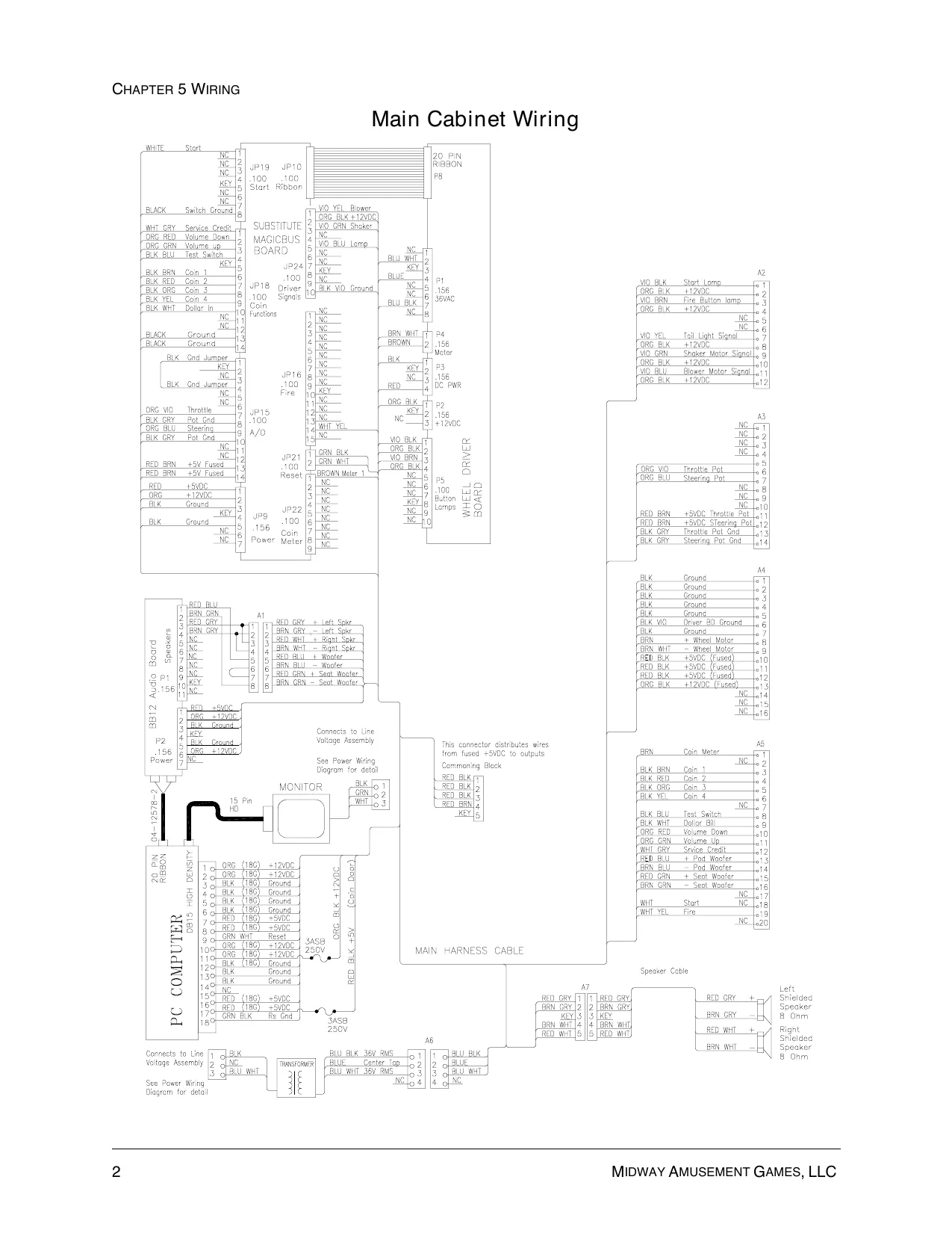
This page is a drawing, shown as the original scan.
2 w ak Secor
ED BRN n3c BLK.
erie ReMi EL [200}-NC.
RED a Me cent
CT 2B Ground echt —fene
sot Zot Soa Stein (ot ee a ra aoe eee sf te patie Bef NC
45 BRN. Coin Meter 2h Ne ) ERE oom co 3 otc <tike sotaiee
Test Swen Pera fi oe ae (o-f aie et — eure Da feta Se toa
Sot iee Be {ec E ED ar gen Neer Bel BRN Ge — Sent Vioofer ratte Pot +500 STeerieg Poll Tpraltie Pat Gre
Start
LU
Pod Wiring
RN YEL fort ond HNL YEL or on GaN YE Eo ond Puc
‘ing Diagram for det CHAPTER 5 WIRING
BLK GRY _Throte Groune_--f THROTTLE,
| ORb VO Thotle Sense | [> [I | [2 WoDULE assy |
| HED BA +50 thatle | 2) |2 | bela ale |
8 or Eqn Switch Grouns B21. pLact
| tart Button | | | WHITE, |
Fire Sutton [2] |2 CWHT YEL in wed] (3 oe ak H 3 Dir aa a LO) 18] Blo
| ED BRN | to aev | STEERING |
| ' | air | 2POT |
ORG BLU Sterng Sense BLK GRY Sleering Ground |; [] Ai qeca Tees 4} 3 RGB gS 5k
| (BROWN | —¥ Wheel Motor |° | | RED | MD ahr’ |
| f | 2 | you |
093° F Mt —
Switch Ground BK GaN Con T RED Coin RED.Bx_+0¥0C {Weler) (Fused) Key Coin Meter OWN NO
RED_+ Meter 7 [7 BLK ~ Weler 15 ||3 17
[con] METER
| CABINET | RED BLK | 15VDC_(Fused) |
WOOFFR ORG BLK #12000 (Fused) |) KEY RED Ground BRN AL Coin 3 Coin A Daler Bi
Srourd
POD CABLE i
A oma Ty OPTIONAL ECA Sgt
“oiume Vel fest Switch pe|.156 COIN VAULT ASSY
TEST SW. BRACKET 3s service
RN
Blower Votor 12VDC—104 Mox 083° Mole BLACK’ EEL Dies] bes MOF LK + Blower Slower (6)
Connects to High
See Power Wiring Diagram for detail Current Transformer | ca au oe ea ea NC inom = SEAT ASSEMBLY
| * | 88, | _ | |
| 7 | 2 GAN Sent Speone- | |} | aN aN | ReoreR |
| siaea[s | nes | LIN | |
| gig] SEZ | = | fer Cable |
v Fels feels Foto
| f | gees | et) [1 Sas | =) | |
| iy | =e LEE | ai VEL | terth round 2| |2 SGN YE | ) |
| 3 | EERE = | = | Tail Light and Cable | |
| | PS | eel | eS | aig | Assembly, A-23859 |
P| 100 BAK __-> shaker E sre trax eater Waar [} ace —(W) acter
| if | 4 | Penny fortn Ground 62] [2 Scan Ye | 12—48 |
5 Motor Cable H~23832 ho
cp i Ss) pil is B4|3 IS e2 |e Boas {5
2| 0
- RAL oe ax + 13 [oR BLK) Io) BI | cry wr {S| fen
Mipway AMUSEMENT GAMES, LLC AC POWER CORD /~
IDC Power Cord
Country Specific
nlet
ng Plate
BLACK
BLK _RED SOY BLK _YEL_HOT ~. | BLACK
LINE GRN_YEL weyreal FILTER NEGERA [WHITE
ORN_YEL
GRN_YEL TE BLACK 5 GRN_YEL LIGHT OF FIXTURE >C GAME
9000
Diagram for Dete Con See Continuation ring Diagram for > Pod AC Cable, H-2387: cameo oN ma 006006000080 GRN_YEL BEZEL | COMPUTER GRN_YEL PC CASE PLATE Power Wiring Diagram CHAPTER 5 WIRING
CHAPTER 5 WIRING
SUBSTITUTE BOARD S11 DIP SWITCH SETTING TABLE
Function Swi Sw2 Sw3 Sw4 Sw5 Sw6 Sw7 Sw8
Not Used On Not Used Off
Not Used On Not Used Off
Not Used On Not Used Off
Not Used On Not Used Off
Arctic On
Not Valid Position Off
Not Used On Not Used Off
Not Used On RS-232 Off
Disable Watchdog On Enable Watchdog Off
Default position is shown in boldface type.
S2 DIP SWITCH TABLE
Function Swi Sw2 Sw3 Sw4 Sw5 Sw6 Sw7 Sw8
Boot Diag On Boot Game Off
Not Used On Not Used Off
Not Used On Not Used Off
Not Used On Not Used Off
Not Used On Not Used Off
Not Used On Not Used Off
Not Used On Not Used Off
Not Used On Not Used Off
Default position is shown in boldface type.
CHAPTER 5 WIRING
SUBSTITUTE BOARD LED INDICATOR STATUS TABLE
Designation Location Function Color State Meaning
| D28 | Near fuse F2 & | Indicator | Red | OFF | No +5V |
JP15 connector ON +5V Present BLINKING Intermittent +12V
| D25 | Near fuse F1 | Indicator | Red | OFF | No +12V |
ON +12V Present BLINKING Intermittent +12V
| D24 | Near US | Indicator | Red | OFF | Not in use |
ON Communication error BLINKING Normal operation
| D23 | Near U5 | Indicator | Red | OFF | Not in use |
ON EEPROM Not Responding BLINKING Normal operation
| D22 | Near U5 | Indicator | Red | OFF | Not in use |
ON Security error BLINKING Normal operation
| Dai | Near U5 | Indicator | Red | OFF | Not in use |
ON Board reset BLINKING Normal operation
| D17 | Near US | Indicator | Green | OFF | Faulty Board |
ON Faulty Board BLINKING Normal operation
| D18 | Near US | Indicator | Green | OFF | Not in use |
ON Faulty Board BLINKING Normal operation
| D14 | Near US | Indicator | Green | OFF | Not in use |
ON Faulty Board BLINKING Normal operation
| D20 | Near US | Indicator | Green | OFF | Not in use |
ON Faulty Board BLINKING Normal operation
| D26 | Near JP9 | Indicator | Red | OFF | No power |
ON +5V present BLINKING Intermittent power
MIDWAY AMUSEMENT GAMES, LLC
AUDIO AMPLIFIER LED INDICATOR TABLE CHAPTER 5 WIRING
Designation Location Function Color State Meaning
| LED 1 | Upper Center | Fault Indicator | Red | Off | Normal Operation |
(CR1) Nearest C3
On Locked-Up (note 1)
Blinking Overload (note 2)
| LED 2 | Lower Center | Fault Indicator | Red | Off | Normal Operation |
(CR2) Near U2 & U6
On Locked-Up (note 1)
Blinking Overload (note 2)
Notes:
- Active output protection circuit. To reset circuit, clear fault and switch off power.
- Blinking caused by either intermittent audio overload or overheating. LED is only supposed to blink during start-up.
WHEEL DRIVER LED INDICATOR TABLE
| LED 1 | Right Center | Indicator | Red | Off | Not Used |
Nearest C5 & P2
On Normal Operation Blinking Power Fault (note 1)
Notes:
- The regulated power supply voltage source is monitored by LED 1, which should remain lit non-stop. Blinking or failure to illuminate indicates an intermittent connection, power problem, circuit fault, etc.
CHAPTER 5 WIRING
NOTES
8 MIDWAY AMUSEMENT GAMES, LLC
CHAPTER
TROUBLESHOOTING
+ Before servicing electronics, turn off AC power to the VGM. Wait for capacitors to discharge. + Before touching or handling electronic assemblies, discharge static electricity on your body. To discharge static, begin by connecting the line cord to a properly grounded outlet, but do not turn on the power! Next, touch the safety ground stud of the power supply chassis. Store electronic assemblies in an anti-static area. Use anti-static bags to store or transport circuit boards. Transport the hard drive in original shipping container. + Do not remove or connect electronic assemblies when the power to the cabinet is switched on. Otherwise you'll damage electronic assemblies and void the warranty. + Replace ground wires, shields, safety covers, etc., upon completion of maintenance or service. Install and firmly tighten all ground and mounting screws.
COIN MECHANISM AND PRICING TROUBLESHOOTING
Symptom Cause Required Action
+ Video Game Machine (VGM) accepts currency or tokens, but number of credits per coin or bill is incorrect. Improper settings at Pricing Menu 1. Access Diagnostic Menu, then select SWITCH TEST. Conduct test to confirm operation of game switches. Access Pricing Menu, then select one of the available pricing options to verify settings.
Faulty wiring Confirm cabinet wiring is correct for this game. Assure coin meter and coin switches connect properly to control input wires.
+ VGM will not accept currency or tokens.
+ VGM will not enter play mode.
+ Audio and video are present. Improper currency Unlock and open cash door. Empty cash box and inspect revenue for counterfeit currency. Check vault. Remove any items that block mechanism’s path.
Faulty coin mechanism Unlock and open coin door. Check each mechanism for proper mounting. + Remove mechanism. + Clear currency path. + Reinstall mechanism and close latch.
Tilted coin mechanism or game Verify mechanism is level after doors close. Repair or replace coin door if it is bent or damaged. If necessary, adjust cabinet leg levelers to keep mechanisms level.
- Coin indicators do not light Burned-out bulb Burned-out bulbs may appear white or darkened. +Replace burned-out bulb with one identically rated. Check continuity with digital voltmeter.
Open fuse circuit Check fuse continuity with digital voltmeter. If fuse is blown, replace fuse with an identically rated part. If fuse isn’t blown, check wiring.
TROUBLESHOOTING - 2 MIDWAY AMUSEMENT GAMES, LLC
START UP TROUBLESHOOTING
Symptom Cause Required Action + Video Game Machine | Power problem 1. Check power is switched on.
| (VGM) does not start. | 2. | Make sure fans in Arcade Computer are turning. If |
not: Is the power supply connected to its power + VGM appears com- cable? Is power supply turned on?
| pletely non-functional. | 3. | Plug cord into AC power outlet. Verify presence of |
AC line voltage. No audio Improper line volt- Turn off power. Unplug AC line cord. Check line age switch setting voltage switch. If necessary, set it to agree with local AC line voltage. Retest game. No illumination
| No video display | Open fuse | 1. | Turn off power. Examine fuse on power chassis, |
cabinet wall or electronic equipment shelf. + Replace faulty fuses with identically rated parts. + Turn on game power. If fuse opens again, check wiring harness and connectors.
| Faulty wiring | 1. | Remove line cord. Test line cord, power plug, and |
IEC connector for breaks or damage. + Verify continuity of each wire in cord. + Install cord on power chassis. + Press connector firmly to seat it.
- Assure that cabinet wiring harness connectors fully seat in corresponding power supply and board connectors.
- Inspect wiring for breaks or damage. Video Game Machine | Faulty coin mech- | 1. Unlock and open coin door.
| (VGM) does not start. | | anism | + Check each currency acceptor to assure proper |
mounting. + VGM accepts cur- + Verify each release latch is closed and locked.
| rency or tokens. | 2. | Test mechanism with good and bad coins to see if |
mechanism accepts and rejects currency cor- + Audio and video are rectly.
| present. | 3. | Inspect to see if external acceptor indicators (Pric- |
ing, Flashing Arrows, etc.) are lit.
- Verify each acceptor operates properly by placing it in working game. Replace bad parts.
| Faulty switches | 1. | Access Diagnostic Menu, then select SWITCH |
TESTS. Conduct test to confirm operation of each switch.
- Assure no loose parts or wires are caught in switch contacts.
- Check for continuity in each suspect switch connection (Common to Normally Open or Common to Normally Closed).
- Replace faulty switches (bent levers, broken actuators, etc.).
ARCTIC THUNDER TROUBLESHOOTING - 3
Symptom Cause Required Action
+ Video Game Machine (VGM) does not start.
VGM accepts currency or tokens.
Audio and video are present. Faulty wiring
- Assure no wires are caught in hinges, latches or switch contacts.
- Check wiring continuity from circuit board connectors to acceptors.
Video Game Machine (VGM) appears nonfunctional.
Currency acceptor price indicator is illuminated. Power problem
- Inspect circuit boards under low-light conditions. + The LED’s glow and the fan turns when processor circuits receive voltage and indicate presence of DC from power supply. However, voltages or signals may not be normal.
- Switch on power to game machine and measure DC voltage settings. Refer to the Cabinet Wiring Diagram for specific wiring information and voltage limits. + Set the digital voltmeter to the 20-volt DC setting and measure the power connector pins. Adjust the +5V source if necessary. Set the digital voltmeter to the 2-volt AC setting and measure DC voltages at power connector pins. Any reading here indicates that supply voltages are unstable and may contain ripple or noise.
Faulty wiring
- Switch off power to game. Check both wiring harness connectors and other types of connectors to make sure they fully seat onto mating board connectors.
Faulty circuit boards or Arcade Computer
- Run power-up self-test sequence. Note errors or failures during test.
- Switch off power to Arcade Computer, but NOT the game machine. Wait for HDD to stop spinning, then loosen the thumbscrews on computer cover and remove. Listen for beeping sounds.
TROUBLESHOOTING - 4 MIDWAY AMUSEMENT GAMES, LLC
LINKING PROBLEM TROUBLESHOOTING
Symptom Cause Required Action
+ Cannot connect multiple Video Game Machines (VGMs) together Faulty wiring 1. Install required crossover between cabinets. Each coupler connects two VGMs (one pair). Do not use standard telephone type couplers or wiring for linking. Use only 10 Base-T, Ethernet-type, Category 5, twisted-pair wiring. Do not overextend linking cables supplied with VGM.
Improper linking hardware Use required network hub for your local network. A Hub Link Kit permits up to four VGM connections. Array completion requires basic kit brackets and spacers.
+ VGM does not recognize other players in linking operation
+ VGM functions normally by itself Improper settings Record any error messages that occur during selftest. Check that each VGM has a unique ID number. Access the Diagnostic menu, then select LINKING TEST. Confirm the link is enabled.
Power problem Verify the hub receives power. AC adapter wires are thin and easily damaged.
Faulty wiring (3 or more VGMs) Inspect hub indicator lights. + Illuminated indicator lights for each active port light up if the cable(s) are properly connected.
- Check for cable continuity from hub to VGM for each indicator that failed to light. Assure no loose wires are caught in hinges, doors or under cabinet. Verify linking cable connects to CPU Board for each game. Verify each linking cable operates properly by placing it in a working game.
TROUBLESHOOTING - 5
LINKING PROBLEM TROUBLESHOOTING
Symptom Cause Required Action
+ Some Video Game Machines (VGMs) in group link properly, while others do not Improper hub switch setting 1. Assure switches on hub are set according to kit instructions. (VGMs on a network do not require couplers. Hub has electronic crossover.) Inspect hub indicator lights for link activity. See manufacturer’s literature for diagnostics.
Wrong software version Verify all linked VGMs use same software version. Machines with different versions will not recognize each other. Contact your distributor for a software update if needed.
Faulty wiring (2 VGMs) Insert only the supplied crossover connection between coupled VGMs. Standard couplers appear identical to devices supplied with games, but do not include an internal crossover. Verify each linking crossover coupler operates properly by placing it in a working link between two VGMs.
Faulty wiring (3 or more VGMs) Use an additional crossover connector and cable to extend game or hub link connection. Two crossovers cancel each other out and results in same problem as no link crossover. Connect cables directly to hub. Do not use a crossover coupler and hub together in single network. Separate communications wiring from other wiring. Wires that must cross can only cross at right angles to limit noise pickup.
TROUBLESHOOTING - 6 MIDWAY AMUSEMENT GAMES, LLC
PLAYER CONTROL TROUBLESHOOTING
Symptom Cause Required Action
+ Intermittent or completely non-functional player controls
+ Video Game Machine (VGM) starts normally. Faulty switches or lamps 1.
2. Access the Diagnostic Menu, then select SWITCH TEST. Conduct test to confirm switch operation. Access Diagnostic Menu, then select LAMP TEST. Conduct test to confirm lamp operation. Check for loose parts or wires caught in switch contacts. Check continuity at each switch connection (Common to Normally Open or Common to Normally Closed). Verify player control operates properly by placing it in working VGM. Verify light bulbs used for dashboard switches are type specified in parts listing. Other types will light, but may produce too much heat. Excess heat may cause switches to bind.
Faulty switch wiring Check for wires caught in door hinges, latches, or switch contacts. Verify harness connectors are attached and fully seated. Assure control switches connect properly to control input wires. Check cabinet wiring is correct for this VGM.
+ Steering pulls to one side Faulty Wheel Driver Board Access the Diagnostic Menu, then select CALI- BRATE FEEDBACK. Perform the calibration sequence. Locate power amp on Wheel Driver Board’s large heatsink. Test Board and replace bad part or board if necessary.
+ No wheel feedback
- Steering does not aim vehicle as expected Improperly set calibration Access Diagnostic Menu, then select CONTROL- LER TEST. Select and perform one of the test sequences to aid in correcting calibration.
Faulty circuit Examine fuses and cables on Wheel Driver Board. Check cables and wiring between Arcade Computer, interface board, wheel driver and motor. Replace bad parts.
Faulty motor Inspect motor. Refer to the Steering Assembly Service instructions in Chapter 3 for complete details.
TROUBLESHOOTING - 7
Symptom Cause Required Action
+ Sloppy, unpredictable or ineffective steering
+ Video is present
+ Video Game Machine (VGM) operates normally Blocked or faulty fan 1. Fan located on power supply acts as an exhaust fan; with power switched on, check fan airflow to assure that nothing blocks airflow.
Faulty mechani- Inspect motor for faulty or worn belts, bearings, cal parts couplings, gears, etc. Refer to the Steering Assembly Service instructions in Chapter 3 for complete details.
Faulty Wheel 1. Inspect Wheel Driver Board under low-light condi- Driver Board tions. To indicate presence of AC from the transformer the LED’s glow when voltage is received. However, voltages or signals may not be normal. Examine fuses and cables on Wheel Driver Board. Replace bad fuses. Use digital voltmeter to verify AC voltage between each fuse holder and ground. Measure approximately 25V. See Wiring Diagram. Use the 20-VAC setting on digital voltmeter to measure DC voltage at motor. Do not move steering wheel, drive belt, or motor while making this measurement. Any reading indicates unstable supply that may contain ripple or noise. Select CONTROLLER TEST from the Diagnostic Menu. Follow on-screen instructions to verify operation of the wheel motor and steering position sensor. Verify proper operation of Wheel Driver Board by placing it in working VGM.
Loose or worn drive belt Inspect motor for faulty or worn belts, bearings, couplings, gears, etc. Refer to the Steering Assembly Service instructions in Chapter 3 for complete details. If drive belt isn’t worn or damaged, check its tightness.
TROUBLESHOOTING - 8 MIDWAY AMUSEMENT GAMES, LLC
VIDEO TROUBLESHOOTING
Symptom Cause Required Action
Monitor appears nonfunctional
Audio is present
Video Game Machine (VGM) controls operate normally Power problem 1. Verify connection of AC Power to video monitor. Inspect neck of CRT in dim light. Glowing filament near CRT base confirms monitor circuits receive power. However, voltages or signals may not be normal.
Faulty wiring Switch off power. Verify that video signal and Remote Adjustment Board connectors seat properly on Video Monitor Board. Assure that video cables connect to circuit boards and Arcade Computer. Assure that no wires are caught on chassis or mounting brackets.
Improper monitor adjustments Try setting Brightness and Contrast above minimum levels.
Faulty monitor circuitry Check AC line for a blown fuse on Video Monitor Board. Replacement fuses must be identically rated. If the fuse is good, verify video monitor operates correctly by placing it in a working VGM. If monitor is bad; Check monitor power supply. If the power supply is good, Check monitor horizontal output transistor and related circuitry.
- Graphic images from game do not appear
No audio
Power-up self-test runs Improper components Verify circuit boards are correct for this game. Labels on each board record manufacturers’ name, assembly number and hardware version. Verify HDD is correct for this game. Label on HDD records assembly number and software version.
Hard Disk Drive (HDD) problems Allow game to load normally. Note and record any error messages that occur during self-test.
Power Problems Turn on Power. Use 20-volt DC setting on digital voltmeter to measure DC voltages present at Power connector pins. Verify +5V source if it is adjustable. Refer to Cabinet Wiring Diagram for specific wiring information and voltage limits. Use 2-Volt AC setting on digital voltmeter to measure DC voltages at Power Connector pins. Any reading indicates the supply voltages are unstable and may contain ripple or noise.
White areas at screen edges appear tinged with color
Dots at screen edges appear ovoid or cylindrical Picture tube dynamic convergence is out of alignment Have service bureau dynamically re-converge monitor. This procedure requires removing and repositioning yoke. Service bureau must follow instructions from monitor manufacturer.
TROUBLESHOOTING - 9
Symptom Cause Required Action
+ Video images tear or roll, or have black bar Faulty wiring 1. Check connectors and cables between circuit boards and monitor for wiring continuity.
| down middle of screen | 2. | Assure connection of all cabinet ground wires, |
especially at video monitor chassis.
Faulty monitor cir- | 1. Verify video monitor operates correctly by concuitry necting it to working game machine.
- Assure video monitor is correct type for this game. Video monitors with wrong resolution can’t lock sync.
| Improper sync | 1. | Make sure Video Board emits proper type of sync. |
| signals | 2. | Verify jumpers are set correctly for monitor. |
| Electromagnetic | 1. | Move game cabinet further away from machines, |
fields appliances, or other video games.
| + Missing colors | Faulty wiring | 1. | Check connectors and cables for wiring continuity |
from circuit boards to video monitor.
| Faulty monitor | 1. | Verify video monitor operates correctly by con- |
color drive cir- necting it to a working game machine. cuitry
+ Onecoloris dimmer or | Maladjusted color | 1. Access Diagnostic Menu, then select MONITOR
| brighter than others | bias pots | TEST. Perform the COLOR BARS TEST. |
+ Adjust three bias pots for best colors. (Most + Whites appear tinted monitor neck boards include these pots.)
| everywhere on screen | 2. | Check White Screen. Touch up controls. |
+ If whites still seem tinted, have service bureau rejuvenate picture tube.
| + Picture is too narrow | Maladjusted WIDTH | 1. | Access Diagnostic Menu, then select MONITOR |
pot. TEST. Perform CROSSHATCH TEST.
- Adjust screen width using the width pot on Monitor Remote Control Board, located behind coin door.
| + Picture is too short | Maladjusted | 1. | Access Diagnostic Menu, then select MONITOR |
HEIGHT pot or TEST. Perform CROSSHATCH TEST. damaged vertical + Adjust screen height using the height pot on the circuit Monitor Remote Control Board behind coin door. + If pot has no effect, service vertical output circuit.
| + Picture seems shifted | Maladjusted | 1. | Access Diagnostic Test, then select MONITOR |
| to one side | HORIZONTAL | TEST. Perform CROSSHATCH TEST. |
POSITION pot + Adjust Horizontal Position pot for best picture using the Monitor Remote Control Board behind coin door.
| + Keystone-shaped pic- | Shorted turns in | 1. | Substitute working yoke. | |
| ture | yoke | 2. | Have service bureau converge monitor. |
- Retest monitor.
TROUBLESHOOTING - 10 MIDWAY AMUSEMENT GAMES, LLC
| Symptom | Cause | Required Action |
| + Blotches of color | Picture tube aper- | 1. | Demagnetize monitor with external degaussing |
| appear on screen | ture mask is mag- | coil. Take care not to magnetize neighboring |
netized games. Monitor may be left on or off during this procedure.
| + White areas in center | Picture tube purity | 1. | Turn on Video Game Machine (VGM). | |
| of screen appear | or static conver- | 2. | Access Diagnostic Menu, then select MONITOR |
| tinged with color | gence is out of | TEST. Perform tests for CROSSHATCH, RED, |
alignment GREEN and BLUE screens to correct monitor dis-
- Object edges have play problem. fringe of one or more + Display screen with the most severe problem. colors + Locate the Purity and Static Convergence ring magnets on monitor neck. To minimize, observe screen and adjust magnets. Follow instructions from monitor manufacturer.
| + Picture is dim or faded | Maladjusted | 1. | Access Diagnostic Menu, then select MONITOR |
BRIGHTNESS pot TEST. Perform COLOR BARS TEST. Adjust or subnormal pic- Brightness and Contrast using pots located on ture tube emission Monitor Remote Control Board, behind coin door.
- If pots have no effect, have service bureau rejuvenate picture tube.
ARCTIC THUNDER TROUBLESHOOTING - 11
TYPICAL CUTAWAY REAR VIEW
A
TROUBLESHOOTING - 12 MIDWAY AMUSEMENT GAMES, LLC
AUDIO TROUBLESHOOTING
Symptom Cause Required Action
+ No audio
+ Video is present
+ Video Game Machine (VGM) appears to operate normally Improper volume setting 1.
2. Access Main Menu, then select VOLUME LEVEL. Make sure Attract Mode Music is enabled. Verify all volume levels are properly set well above zero. If necessary, change volume levels to make game audible.
Faulty wiring Switch off power to game machine. Check wiring harness connections attach and fully seat onto mating board connectors. + Verify harness connects to CPU Board.
- Check audio cable connectors in same way.
Faulty or obstructed speaker Remove speaker grilles and inspect speakers. Clear loose parts and wires from magnets, mounting screws, terminals, and speaker cones.
Faulty Audio Board Verify proper operation of Audio Board by placing it in a working game machine.
Power Problems Use 20-volt DC setting on digital voltmeter to measure DC voltages present at Power connector pins. Verify +5V, -5V and +12V sources. Refer to Cabinet Wiring Diagram for specific wiring information and voltage limits.
+ Audio is distorted, muffled or has missing frequencies. Faulty or improper speaker Switch off power to game machine. + Remove speaker grilles and inspect speakers. + Verify speakers are full range (100 to 10,000 Hz response) and rated for at least 20 watts. Woofers must be rated for at least 40 watts. Verify proper speaker operation by placing speaker in question in a working game machine.
Faulty wiring Multiple-speaker installations: Check for reversed speaker wiring. Weak or low frequencies and thin or hollow sound quality are symptoms of incorrectly phased speakers.
*Sound tests may not detect this condition, but you can hear it during operation.
+ Dead sound channel Faulty speaker Access Diagnostic Menu, then select Speaker Test. Perform one or several of the available tests to check speakers. Verify proper speaker operation by connecting speaker in question to working game machine.
Faulty wiring Verify cabinet wiring is correct. Check audio wiring connection to speakers. Check audio cable connection is fully seated. Check for broken or shorted wires.
TROUBLESHOOTING - 13
Symptom Cause Required Action
- Constant low hum from all speakers. Faulty wiring 1. Verify cabinet wiring is correct. Verify separate wires for each speaker, not a common return, in cabinet wiring. Check connection of all cabinet ground wires.
Faulty power supply Use 2-Volt AC setting on digital voltmeter to measure voltages at speaker terminals. Any reading will indicate an unstable supply containing ripple or noise.
MISCELLANEOUS PROBLEM TROUBLESHOOTING
Symptom Cause Required Action
+ Marquee lamp is intermittent or non-func- Faulty fluorescent tube 1. Remove fluorescent tube from sockets. Install new lamp if ends are darkened or cracks are visible.
| tional | 2. | Check continuity of both fluorescent tube fila- |
ments.
| + Video Game Machine | 3. | Check lamp ballast is rated for local AC line volt- |
(VGM) starts and age and frequency.
| plays normally | 4. | Verify fluorescent tube operates by placing it in |
working game machine.
Faulty lamp fixture | 1. Verify good connection between lamp pins and socket contacts.
| Faulty wiring | 1. | Measure fluorescent lamp AC voltages. Check |
wiring and connector continuity from the AC power chassis to lamp assembly.
| + VGM operates nor- | Obstructed fan | 1. | Check for blocked air flow at bottom and rear of |
mally cabinet. + Switch off power to game machine. Use a high- + Cabinet becomes power vacuum cleaner to remove dust from vent warm after several holes.
| hours of use | 2. | Make sure game machine is not near a heat |
source. Move game cabinet away from sources of heat if necessary.
| Faulty Wiring | 1. | Check fan wiring and connectors. | |
| Faulty fan | 1. | Check operation of all fans. | |
| + Error messages | Faulty hardware | 1. | Check assembly identified in error messages, |
appear on screen RAM, ROM, Battery, etc.
- Call your authorized distributor for help with unresolved screen messages.
TROUBLESHOOTING - 14 MIDWAY AMUSEMENT GAMES, LLC
This page carries no recoverable text. It is a drawing or a photograph. See the original scan.
WARNINGS & NOTICES
If you or anyone in your family has experienced symptoms linked to an epileptic condition (e.g. seizures or loss of awareness), immediately consult your physician before using any video games.
We recommend that parents observe their children while they play video games. If you or your child experience the following symptoms: dizziness, altered vision, eye or muscle twitching, involuntary movements, loss of awareness, disorientation, or convulsions, discontinue use immediately and consult your physician.
COPYRIGHT & TRADEMARK NOTICE You may not reproduce any part of this publication by mechanical, photographic, or electronic means. You may not prepare phonograph recordings of this document. You may not transmit this publication or otherwise copy it for public or private use, without permission from the publisher.
Entire contents of this manual copyright ©2000 Midway Amusement Games LLC. All rights reserved. Midway® and Arctic Thunder™ are trademarks of Midway Amusement Games LLC.
NOTICE This equipment generated, uses and can radiate radio frequency energy and if not installed and used in accordance with the instruction manual, may cause harmful interferance to radio communications. Operation of this equipment in a residential area is likely to cause harmful interference in which case the user will be required to correct the interference at his own expense.
NOTICE When Midway Amusement Games, LLC ships a VGM, it complies with FCC regulations. Your label is proof of compliance. Legal repercussions to the owner or distributor may result if the label is missing or damaged. If your VGM does. not contain an FCC compliance label, call Midway Amusement Games, LLC immediately.
For Service:Call your authorized Midway Amusement Games, LLC distributor.
Mipway AMUSEMENT Games, LLC 3401 N. CALIFORNIA AVE. CHICAGO, ILLINOIS 60618-5899 USA Visit our Web site at http:/www.midway.com
Entire contents of this manual copyright © 2000 Mipway AMUSEMENT GAMES, LLC . All rights reserved.