Battlezone DP-156-1st-01B
Battlezone (rev 2) (Atari, 1980) · Drawing Package · 1 pages · original scan
=
ra
[00000000000n
Figure 2A
ae Sheet 1, Side B DP-186.01 st printing Di ata Figure 1
BES
FA i :
ela a
em Fett ot
Fl amy Fa
rr i i E3[, ely 5 [. San53 oe i 3 a
Fst ¢ 3 88 8 g cig ge 2d (|
11121314
3828
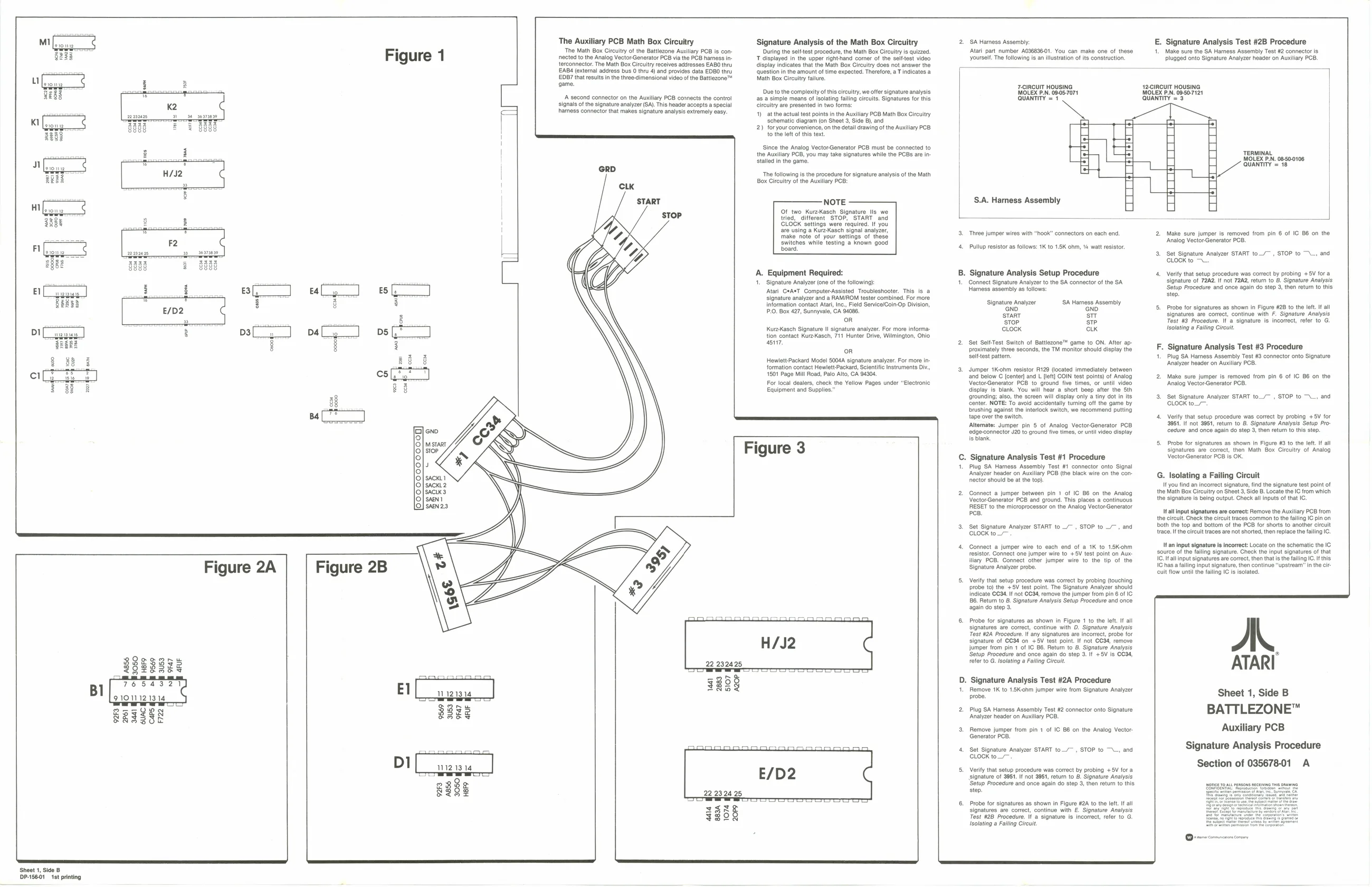
11121314. The Auxiliary PCB Math Box Circuitry ‘The Math Box Circuitry of the Battlezone Auxiliary PCB is con ‘nected to the Analog Vector-Generator PCB via the PCB harness interconnector. The Math Box Circuitry receives addresses EABO thru EAB4 (external address bus 0 thru 4) and provides data EDBO thru results in the three-dimensional video of the Battlezone™
‘A second connector on the Auxiliary PCB connects the control signals of the signature analyzer (SA). This header accepts a special harness connector that makes signature analysis extremely easy. Signature Analysis of the Math Box Circuitry During the setttest procedure, the Math Box Circuitry i quizzed. aisplayed In the upper righthand comer of the seltest video display indicates that the Math Box Circultry does not answer the {question in the amount of time expected. Therefore, aT indicates a Math Box Circuitry tlle Due to the complexity ofthis circuitry, we offer signature analysis as a simple means of isolating failing circuits. Signatures for this Circuitry are presented in two forms:
- at the actual test points in the Auxiliary PCB Math Box Circuitry schematic diagram (on Sheet 3, Side 8), and
- foryour convenience, on the detail drawing of the Auxiliary PCB to the left of this text.
Since the Analog Vector-Generator PCB must be connected to the Auxiliary PCB, you may take signatures while the PCBS are installed in the game.
‘The following is the procedure for signature analysis of the Math Box Circuitry of the Auxiliary PCB:
A. Equipment Required:
- Signature Analyzer (one ofthe folowing} Atari CeAeT Computer-Assisted Troubleshooter. This is a signature analyzer and a RAM/ROM tester combined. For more information contact Ata, nc, Feld Serice/Goin-Op Division, P10. Box 427, Sunnyvale, CA 84086, oR KurzKasch Signature Il signature analyzer. For more informa tion contact KureKasch, 711 Hunter Drive, Wilmington, Onio 817, or Hewlett-Packard Mode! 50088 signature analyzer. For more in formation contact Hewlett Packar, Scientiic Instruments Oi, 1801 Page Mill Road, Palo Alto, CA 94308 For local dealers, check the Yellow Pages under “Electronic Equipment ané Supplies
H/J2
22 232425 — — Figure 3
- SAHamess Assembly ‘Atari part number A036896-01. You can make one of these ‘yourself. The following is an illustration of its construction.
MOLEX P.N. 085.7071 QUANTITY = 1 E. Signature Analysis Test #2B Procedure
- Make sure the SA Haress Assembly Test #2 connector is, plugged onto Signature Analyzer header on Auxiliary PCB.
42CIRCUIT HOUSING MOLEX PLN. 09:50-7121, | QUANTITY = 3 | T.CIRCUIT HOUSING
‘TERMINAL, MOLEX P.N. 08-50-0106 QUANTITY = 18 TITI
S.A. Harness Assembly Cr
I 0
- Three jumper wires with “hook” connectors on each end,
- Pullup resistor as follows: 1K to 1.5K ohm, % watt resistor
B. Signature Analysis Setup Procedure
- Connect Signature Anayzer to the SA connector of the SA Hammess assembly as follows!
Signature Analyzer SA Hames Assembly ‘GND ‘GND START sit ‘STOP STP. clock CLK
- Set SolfyTest Switch of Battlezone™ game to ON. After approximately three seconds, the TM monitor should display the selftest pattern,
- Jumper 1Kohm resistor R129 (located immediately between ‘and below C [center] and L {lett} COIN test points) of Analog Vector-Generator PCB to ground five times, or until video display is blank. You will hear a short beep after the Sth ‘grounding; also, the screen will display only a tiny dot in its ‘center. NOTE: To avoid accidentally turning off the game by brushing against the interlock switch, we recommend putting tape over the switch. Altemate: Jumper pin § of Analog VectorGenerator PCB ‘edge-connector J20 to ground five times, or until video display Is blank.
C. Signature Analysis Test #1 Procedure Plug SA Hamess Assembly Test #1 connector onto Signal ‘Analyzer header on Auxillary PCB (the black wire on the conrector should be at the top).
2 Connect @ jumper between pin 1 of IC B6 on the Analog Vector Generator PCB and ground. This places a continuous RESET to the microprocessor on the Analog Vector Generator POB.
- Set Signature Analyzer START to_/~ , STOP to, and (CLOCK to _—
- Connect a jumper wire to each end of a 1K to 1.8Kohm resistor. Connect one jumper wire to +5V test point on Aux: iiary PCB. Connect other jumper wire to the tip of the Signature Analyzer probe.
- Verily that setup procedure was correct by probing (touching probe to) the +SV test point. The Signature Analyzer should indicate C034, If not C034, remove the jumper trom pin 6 of IC B6. Return to 8. Signature Analysis Setup Procedure and once again do step 3.
- Probe for signatures as shown in Figure 1 to the left. If all signatures are correct, continue with 0. Signature Analysis Test #2A Procedure. It any signatures are incorrect, probe for signature of CC34 on +5V test point. I not C634, remove jumper from pin 1 of IC B6. Retumn to B. Signature Analysis ‘Setup Procedure and once again do step 3. I +5V is CC34, refer to G. Isolating a Failing Circuit
D. Signature Analysis Test #2A Procedure
- Remove 1K to 1.5K-ohm jumper wire from Signature Analyzer probe.
2, Plug SA Hamess Assembly Test #2 connector onto Signature ‘Analyzer header on Auxiliary PCB,
- Remove jumper from pin 1 of IC 88 on the Analog Vector: Generator PCB,
- Set Signature Analyzer START to_/~ , STOP to “and CLOCK to
- Verify that setup procedure was correct by probing +5V for a signature of 3961. If not 3961, retum to 8. Signature Analysis atup Procedure and once again do step 3, then return to this, ep.
- Probe for signatures as shown in Figure #2A to the left. If all signatures are correct, continue with E. Signature Analysis Test #28 Procedure. It a signature is incorrect, reter to 6. Isolating a Failing Circult.
- Make sure jumper is removed from pin 6 of IC B6 on the ‘Analog Vector-Generator PCB.
- Set Signature Analyzer START to_/— , STOP to, and CLOCK to.
- Verity that setup procedure was correct by probing + SV for a signature of 72A2.If not 72A2, retumn to B. Signature Analysis ‘Setup Procedure and once again do step 3, then return to this step.
'5. Probe for signatures as shown in Figure #28 to the left. If all signatures are correct, continue with F. Signature Analysis Test #3 Procedure. Ita signature is incorrect, refer to G. Isolating a Failing Circuit.
F. Signature Analysis Test #3 Procedure Plug SA Hamess Assembly Test #8 connector onto Signature ‘Analyzer header on Auxiliary PCB.
- Make sure jumper is removed from pin 6 of IC B6 on the ‘Analog Vector-Generator PCB.
- Sot Signature Analyzer START to_/~ , STOP to _, and CLOCK to
- Verity that setup procedure was correct by probing +5V for 3951. If not 3951, return to B. Signature Analysis Setup Proedure and once again do step 3, then return to this step.
5, Probe for signatures as shown In Figure #3 to the left. If all signatures are correct, then Math Box Circuitry of Analog Vector-Generator PCB is OK.
G. Isolating a Failing Circuit Ifyou tind an incorrect signature find the signature test point of the Math Box Circuitry on Sheet 3, Sie B. Locate the IC fom which the signature Is being output. Check al inputs of that 1C- Mall input signatures are correct: Remove the Auxiliary PCB from the circult. Check the circult traces common to the falling IC pin on both the top and bottom of the PCB for shorts to another circuit trace. Ifthe circuit traces are not shorted, then replace the filing IC.
Wan input signature is incorrect: Locate on the schematic the IC ‘source of the falling signature. Check the input signatures of that IC. fall input signatures are correct, then tha is the failing IC. If this Chas a failing input signature, then continue ‘upstream’ in the circuit flow until the falling IC is isolated,
A ATARI
Sheet 1, Side B
BATTLEZONE™
Auxiliary PCB
Signature Analysis Procedure
Section of 035678-01 A