Asteroids Cocktail DP-150-2nd-02A
Asteroids (rev 4) (Atari, 1979) · Drawing Package · 1 pages · original scan
VECTOR GENERATOR RAM VECTOR GENERATOR
DATA BUFFER
MICROCOMPUTER SHEET 1, SIDE B
VECTOR GENERATOR PROGRAM COUNTER
MPU DATA BUS SHEET 1, SIDE B,
VECTOR GENERATOR
MEMORY ADDRESS SELECTOR
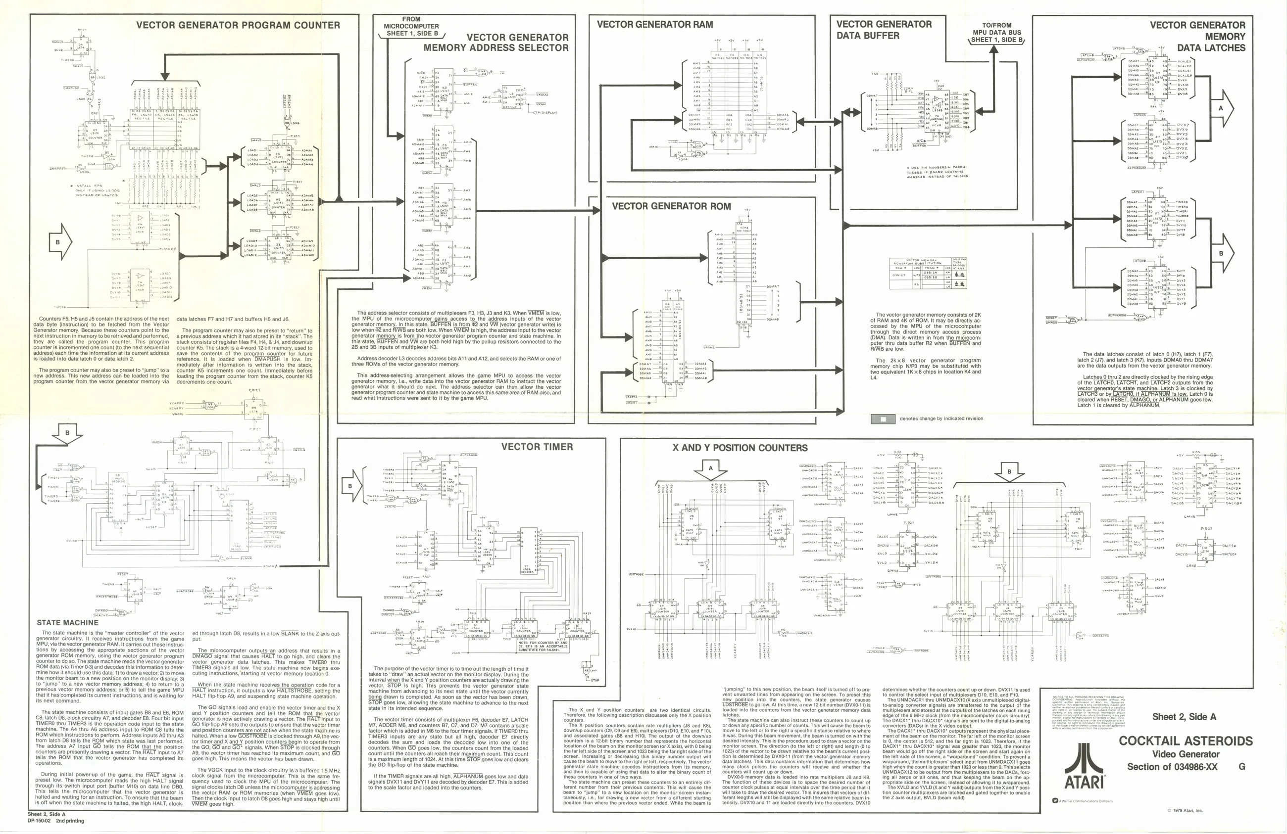
‘The address selector consists of multiplexers F3, H3, J3 and K3. When VMEM is low, the MPU of the microcomputer generator memor low when 82 ana
‘The vector generator memory consists of 2K
of RAM and 4K of ROM. It may be directly acessed by the MPU of the microcomputer through the direct memory access process. (OMA). Data is wrtter Duter thru data buffer R2 when BUFFEN and ‘Counters F5, HS and JS contain the address ofthe next data byte (insiruction) to be fetched from the Vector Generator memory. Because these counters point to the ‘ext instruction in memory to be retrieved and performed, they are called the program counter. This. program ‘counter i incremented one count (o the next sequential address) each time the information at its curent address ing access to, address inputs of the vector | from 2 and WW (vector generator write) is are both low. When VMEM is high, the address input tothe vector ‘is from the vactor generator program counter and state machine. In ‘and VW are both held high by the pullup resistors connected to the 2B and 3B inputs of multiplexer K3. data latches F7 and H7 and buffers H8 and J6.
“The program counter may also be preset to “return” to ‘a previous address which it had stored in its "stack". The stack consists of register files Fa, H4, & J4, and downlup ‘counter KS, The stack isa 4word 12.it memory, used to ‘save the contents of the program counter for future from the microcom-
MEMORY
‘The data latches consist of latch 0 (H7), latch 1 (F7), latch 2 (7), and latch 3 (7). Inputs ODMAG thru ODMA7 are the data outputs from the vector generator memory. ‘Address decoder L3 decodes address bits A11 and A12, and selects the RAM or one of three ROMs of the vector generator memory. Js loaded into data latch 0 or data latch 2. Tt is loaded when after information is written into the stack, The 2kx8 vector ge memory chip NIP3 may be substituted with {wo equivalent 1Kx8 chips in location K4 and us ‘The program counter may also be preset to “jump” toa now address. This new address can be loaded into the program counter from the vector generator memory via This address-selecting arrangement allows the game MPU to access the vector ‘generator memory, Ic, write data into the vector generator RAM to instruct the vector xt. The address selector can th Latches 0 thru 2 are directly clocked by the rising edg ‘and ‘generator what It'should do. ‘allow the vector ‘Outputs from the neratgr's state machine. Latch 3 's clocked by {or program counter and state machine to access this same area of RAM also, and instructions were sent to it by the game MPU. INALPHANUM Is low. Latch 018 RESET DMAGO, or ALPHANUM goes | {ater Ys cleared by ALPHANGW, —
[EE ceretes change by incicates revision
VECTOR TIMER
STATE MACHINE The state machi ‘generator circuity. MPU, via the vector g¢ controller’ of the vector receives instructions from the game ‘out these instruc ing the appropriate sections of the vector ‘generator ROM memory, using the vector generator program ‘Counter to do So. The state machine reads the vector generator ROM data (via Timer 0-3) and decodes this information to deter ‘mine how it should use this data: 1)t0 draw a vector, 2) to move the monitor beam to a new position on the monitor display, 3) toa new vector memory address; 4) 10 return to a Devious vector memory address; or 5) to {hat ithas completed its current instructions, and is wating for its next command, through latch 08, results in a low BLANK to the Z axis out:
“The microcomputer outputs an address that results in a signal that causes HALT to go high, and clears the vector generator data latches. This makes TIMERO thru Ww. The state machine now begns exe: cuting instructions, starting at vector memory location 0. TIMERS signals all ‘The purpose ofthe vector timer isto time out the length of time it takes to “raw” an actual vactor on the monitor display. During the Interval when the X and ¥ position counters are actually drawing the vector, STOP is high. This prevents the vector generator state until the vector curently ‘drawn is completed. As soon as the vector has been drawn, ‘9088 low, allowing the state machine to advance to the nexi When the state machine recel FALT instruction, it outputs a low HALT tlipflop AS, and suspending state machine operation. ss the operation cote for a determines whether the counters count up of down, DVX11 is used te contol the solect input of multiplexers D10, £10, and F10. ‘The UNMDAGXT thru UNMDACK10 ( axis unmultiptexed digital: “jumping” to this new position, the beam itslt "wom appearing on the seroen, To preset this ation into the counters, the ‘state ‘generator causes turned off to preing to its next stat vent unwanted in ~ DATA LATCHES
‘anew 12bit number(OVX0-1) 18 toanalog converter signals) are transferred to the output of the The GO signals load and enable the vector timer ard the X ‘and Y position counters and tell the ROM that the vector for is now actively drawing a vector. The HALT nput to GO tlipstiop A9 sets the outputs to ensure that the vector timer its intended sequence. Y position counters are two id ‘the following description discusses only the X posit {rom the vector generator memory data mulliplexers and stored atthe outputs ofthe ‘The state machine consists of input gates 88 and E6, ROM 8, latch D8, clock circulty A7, and decoder EB. Four bit input ‘TIMERO thru TIMERS is the operation code input to the state ‘The DAGXT” thru OAGXT0" signals ao sont to the digital to-anal fers (OAGs) in the X video out ‘The vector timer consists of multiplexer Fé, decoder E7, LATCH M7, ADDER M6, and counters 87, C7, and D7. M7 contains a scale "The X position coun Contain rate multipliers JB and Ks), or down any speci machine. The A4 thru AB address input to ROM C8 h instructions to perform. Address inputs AO thru AS from latch 08 tells the ROM which state was last performed, ‘The address A7 input GO tells the ROM that the position ‘counters are presently drawing a vector. The HACT input to A? tolls the ROM that the vector generator has completed its ‘and position counters are not active when the state machine is halted. When alow GOSTROBE is clocked through A9, the ve: {or timer and X and Y position counters begin to operste from the GO, GO and GO™ signals. When STOP is clocked thro AQ, the vector timer has reached its maximum count, nd {9008 high. This means the vector has been drawn, factor which is added in MB to the four timer signals, I TIME! ts are any state but all high, decoder E7 directly ‘Sum _and loads the decoded’ low into one of the ‘GO goes low, the counters count from the loaded jr maximum count. This count is amaximum length of 1024 At this time STOP goes low and clears the GO flipfiop of the state machine, ‘sownlup counters (C9, 09 and E8), multiplexers (010, E10, and F10), ‘orto the ight a spec ‘The DAGK1" thru DAGX10" outputs represent the physical place- ‘mento the beam on the monitor. The far lft of the monitor screen {s.0, the center Is 512, and the far right Is 1023. Therefore, i the DAGKT® theu DACXTO® signal was great bam would go of the right side of th Of the screen, a "wraparound’ condition. To prevent @ 3° salect nput from UNMDACK'1 goes than 1023 Floss than 0. This selects LUNMDAGX12 tobe output from the multiplexer to the DACS, fore: Counters is.a 122i binary number that roprosents location ofthe beam on the monitor screen (or X axis), with O being the far eft sie ofthe screen and 1023 boing the far right side a the screen. Increasing or decreasing this binary number output will ‘cause the beam to move tothe right or elt, respectively. The vector Generator state machine decodes Instructions from fis memory, rapable of using that data to alt the binary count of thege counters in one of two ways. “Tho stato machine can preset these counters to an entirely di ferent number from thelr previous cont ‘monitor screen, The 1023) ofthe vector tobe drawn relat than 1028, the monitor feen and start again on rection (fo the loft or right) and length (0 to ‘Beam’s current posi. unter all reach tl trom data latches). This data contains information t many’ clock pulses the counters will reve. and. wh ‘Counters wil count up or down, ‘DVKO memory data Is loaded Into rate multipliers JB and 8, ‘The function of these devices fs to space tho Gesirod number of ‘counter clock pulses at equal intervals overt ‘wll take to raw the desired vector. Tho Insure that vectors o be displayed with the eame relative beam In tensity: DVX10 and 11 are loaded arectly ito the counters. OVK0 ‘wraparound, the multi high when the counts “The VGCK input to the clock circuitry isa buttered 1.5 MHz clock signal from the microcomputer. This is the seme fre- Quency Used to clock the MPU of the microcomputer. The signal clocks latch D8 uniess the microcomputer is addressing the vector RAM or ROM memories (when VMEM goss lov) Then the clock input to latch D8 goes high and stays high until During initial power-up of t preset low. The microcomputer reads the high HALT signal its switch input port (buffer M10) on data line DBO. is the microcomputer that the vector generator is halted and waiting for an instruction. To ensure that the beam ‘is off when the state machine is halted, the high HALT, clock Shoot ?2, Side A DP-15002 2nd printing jame, the HALT signal is tthe TIMER signals are all high, ALPHANUM goes low and data signals DVX11 and DVY11 are decoded by decoder E7. This is added to the scale factor and loaded into the counters. Ing all zeros or all ones, and thus keeping the beam on the ap propriate side on the screen, instead of allowing it to wraparound, ‘The XVLD and YVLO Oc and valid) outputs from the Xana Y posi tlon counter multiplexers are latched and gated together to enable the Z axis output, BVLD (beam valid, tS. This wil ca time period that it ‘beam to "jump" to a new location on the monitor screen insta: taneously, Le, for drawing a new vactor from a different starting position than where the previous vector ended. While the Boam Is Toront lengths wil st COCKTAIL ASTEROIDS
Video Generator
Section of 034986-XX
© 1979 Ata, ne.