Cruisn Exotica 39in Motion
Cruisin' Exotica (Midway Amusement Games, LLC, 2000) · Manual · 121 pages · 71 sections · original scan
FEBRUARY 2000 16-40076-101
OPERATIONS MANUAL FoR 39”DEDICATED GAME WITH MOTION SEAT
Manual Includes Operation & Adjustments + Parts Information + Wiring Diagrams +» Testing & Problem Diagnosis
This page carries no recoverable text. It is a drawing or a photograph. See the original scan.
DECLARATION OF CONFORMITY
MIDWAY AMUSEMENT GAMES, LLC
3401 N, CALIFORNIA AVE. CHICAGO, IL 60618 U.S.A.
WE, HEREBY DECLARE UNDER SOLE RESPONSIBILITY THAT
THE MODEL: ‘cruisin’ EXOTICA 39" MOTION' 40276, 40376, 40476, 40776, 40976, 41076, 41176, 41276, 41376, 41476, 41876, 42076, 42176, 42276, 42376, 47176, 47276
TO WHICH THIS DECLARATION RELATES IS IN CONFORMITY WITH THE FOLLOWING EUROPEAN PRODUCT SAFETY DIRECTIVES:
LECTR« NE’ (PATI 'Y (VE (89/336/EEC AND AMENDMENTS 91/C162/08, 92/31/EEC,93/68/EEC)
ELECTRICAL EQUIPMENT DESIGNED FOR USE WITHIN
CERTAIN VOLTAGE LIMITS DIRECTIVE
(73/336/EEC AND AMENDMENTS 88/C168/02, 92/C210/01, 93/68/EEC,94/C 199/03, 95/C214/02)
AS IS VERIFIED BY COMPLIANCE WITH THE FOLLOWING STANDARDS:
EN55014: 1993 EN61000-4-2: 1995 TEC 801-3: 1984 (EN61000-4-3) EN61000-4-4: 1995 EN61000-4-5: 1995 EN335-1: 1995 IEC 335-2-82 (DRAFT)
Date issued: JANUARY 24, 2000
CEL Bp
CORPORATE V.P. OF QUALITY
QUICK REFERENCE CABINET LINKING INSTRUCTIONS
“<— = | To link two or more cabinets, use the factory installed linking cable and follow the instructions for “Wiring Modifications and Software Setup” located below.
CABINET ARRAYS To create a Video Game Machine (VGM) Array, join the cabinets together. Each VGM comes equipped with the necessary hardware to connect cabinets and provide maximum stability. Hardware is located in the spare parts bag inside the cash box.
To join cabinets, remove the flat-head carriage bolts from the top and rear of adjacent cabinet sides. Position cabinets next to one another and adjust the leg levelers until all holes are aligned. Insert long carriage bolts through the holes in both cabinets, and then fasten in place with the nuts provided.
NETWORK CONSIDERATIONS, Each VGM comes complete with a factory installed network cable.
Take care to protect exposed wiring from player foot traffic, cleaning crews, service personnel, etc. Use approved conduit or wire channels to support cables. Please note that modular connectors do not have strain relief.
Prevent linking cables from becoming damaged by avoiding sources of extreme heat or moisture, and high amounts of electrical energy like neon signs, fluorescent fixtures, two-way radios, cordless phones, power circuits, public address system wiring, etc.
Clearly label all network connections to avoid confusing network cables with computer or telephone circuits.
ae MODIFICATIONS AND SOFTWARE SETUP
Unlock and remove the rear door from the cabinets selected to be part of the array. Inside the cabinet you will find a coil of linking cable with one end already attached to game electronics. Uncoil just enough of the cable to reach game electronics in the next cabinet, then recoil the rest of the cable and tie it in place. Repeat this procedure for each of the other cabinets. Do not reinstall the cabinet door(s) at this time.
- Route the free end of each cable out through the notch located in the rear door opening and plug into the game electronics.
- Make sure excess cable is tied into a coil and that all cables are routed through the notch in the rear door.
- Switch on power and closely observe the screen for each cabinet during start up. Each automatically enters ATTRACT MODE if no errors are found. Refer to Troubleshooting in the operation manual if errors are detected.
- Unlock the coin door for each cabinet to access the operator control buttons inside coin vault. Press and hold the TEST button to enter the menu system. >» Check the EPROM, GUTS, and MAIN information at the bottom of each game’s SELF TEST menu screen. » Verify linked games have compatible software versions. Newer versions may contain instructions previous versions do not, causing games to halt or reset at random. >» Repeat this and all remaining steps for each linked cabinet.
- Press the View 1 or View 2 button to select GAME OPTIONS. Press the ABORT button to activate this item. Set the CABINET #; keeping in mind that each cabinet must have its own individual and unique number. The first cabinet on the left is always cabinet 1, the second is cabinet 2, etc.
Select LINKING TESTS then press the TEST button to activate it. Observe all linked cabinets will be listed in this screen. Refer to Menu System descriptions in the manual for more details.
Select CONTROLS TESTS. Follow on-screen instructions to confirm proper control operation. Press and hold the TEST button to reset steering wheel and pedal travel limits.
Select SOUND TESTS. Confirm operation of all cabinet and seat speakers, and each amplifier.
. Select MONITOR TESTS. Perform all tests and adjustments to ensure high quality video.
. Close and lock the coin door, and reinstall and lock the rear door for each cabinet. Lower the leg levelers for each cabinet until the casters do not touch the floor and the cabinets are level. Lock the levelers in position by tightening the nuts provided.
NOTES
CRUIS’N EXOTICA
SECTION
ONE
OPERATION
; NOTICE: This manual is subject to change without notice. MIDWAY reserves the right to make 7 improvements in equipment function, design, or components as progress in engineering or manufacturing methods may warrant.
Fill out and mail in the Information Card. Include the Video Game Machine (VGM) serial number from the label on the rear of the cabinet. For your records, write the serial number in the manual. SERIAL NUMBER
SAFETY INSTRUCTIONS The following safety instructions apply to operators and service personnel. Read these instructions before preparing the Video Game Machine (VGM) for play. Other safety instructions appear throughout this manual.
DEFINITIONS OF SAFETY TERMS @ DANGER indicates an imminent hazard. If you fail to avoid this hazard, it WILL cause death or serious injury.
@ WARNING indicates a potential hazard. If you fail to avoid this hazard, it COULD cause death or serious injury.
¢@ CAUTION indicates a potential hazard. If you fail to avoid this hazard, it MAY cause minor or moderate injury. CAUTION also alerts you about unsafe practices.
@ NOTICE indicates information of special importance.
The VGM contains glass and fragile electronic components. Use appropriate care when transporting. Avoid rough handling when moving the VGM. Do not move with the power switched on. y WARNING: TRANSPORTING VIDEO GAME MACHINES (VGM).
setting before switching on the VGM. Verify that the fluorescent lamp assembly is correct for the local line voltage.
Operation - 2
If you or anyone in your family has experienced symptoms linked to an epileptic condition (e.g., seizures or loss of awareness), immediately consult your physician before using any video games.
We recommend that parents observe their children while they play video games. If you or your child experience the following symptoms: dizziness, altered vision, eye or muscle twitching, involuntary movements, loss of awareness, disorientation, or convulsions, DISCONTINUE USE IMMEDIATELY and consult your physician.
Operation - 3
PRODUCT SPECIFICATIONS
Operating Requirements Location Electrical Power Temperature Humidity
Domestic 120VAC @ 60Hz 4.0 Amps 32°F to 100°F Not to exceed 95% relative Foreign 230VAC @ 50Hz 2.0 Amps (0°C to 38°C) Japan 100VAC @ 50Hz 4.0 Amps
Cabinet Statistics
| Shipping Dimensions | Shipping Weight (Approx.) | Design Type |
| Width 40" (101.6 cm) | 600Lbs (272kg) Main Cabinet | Sit-In Dedicated Game Machine |
| Depth 100" (254 cm) | 200Lbs (90kg) Control Cabinet | with Steering Wheel Feedback |
| Height 86" (218.4 cm) | 225Lbs (57kg) Seat Assy. | and Motion Seat |
Game Characteristics
| Player Variables | Operator Variables | Diagnostics |
| 1 to 4 players per VGM (with Linking) | Coinage, Play Mode, | Automatic Power-Up Self-Test |
| High Score Recognition | Difficulty, Volume, Audits, | Manual Multi-Level Menu |
Suitable for All Ages (AAMA Certified) Statistics System
Equipment Characteristics Video Display Monitor Medium Resolution RGB 39” (99 cm) CRT
Audio System Digital Stereo 5” (12.7 cm) Coaxial Full Range Speakers
Currency Acceptors 2 Coin Mechanisms Dollar Bill Validator Ready Electronic Coin Acceptor Ready
PRODUCT CONFIGURATION
@ Stand Alone Video Game Machine Each VGN is ready to play right out of the box. Operators may use the menu screens in the game menu system to determine some player variables in advance or leave the choices up to the players.
@ Linked Video Game Machines Linking allows players to compete against each other on a single course. Operator menus are used the same way as in stand-alone VGMs. Linking cables to connect two or more VGMs are factory installed. Refer to Quick Reference Cabinet Linking Instructions in the pages preceding this section for more detailed instructions.
Operation - 4
NOTICE This game machine comes equipped with two AC power cords and requires a location with two available electrical outlets.
Typical Video Game Machine Array
SET-UP
1. Remove all items from the shipping containers and set them aside. Remove all packing material. Inspect the exterior of the main cabinet, control cabinet and the motion seat pedestal for any damage.
Remove the keys from the steering wheel. Unlock and open the rear door, and the coin and cash boxes. Electrical cords, mechanical components, and assorted spare parts are packed inside the cash box.
Install one nut onto each leg leveler. Tilt as needed to locate four threaded holes under both the main cabinet and control cabinet. Install a leveler and nut into each hole. Do not tighten nuts at this time.
Operation - 5
YAN NUT 1/2-13
HARD SWNEL ©
Location of Casters and Levelers
- The main cabinet is mounted on four swivel casters. Roll the cabinet to its intended location, maintaining clearance between the cabinet and walls, drapes, other games or obstructions. Roll the control cabinet near the main cabinet, leaving enough space to attach the wiring harness. Mate each cable from the control cabinet to the main cabinet. Press firmly, but do not force, the keyed connectors to seat the contacts. Slide the control cabinet toward the main cabinet between the mounting brackets, guiding the harness and cables into the main cabinet.
MAIN CABINET
Mounting Bracket Location
Operation - 6
Lower and adjust each leg leveler on the control cabinet until it is stable and level. Adjust the levelers until the bottoms of both pieces are flush and parallel with each other. Inspect for binding or pinched wires. Align the bracket holes with the mounting holes in the base of the control cabinet. Insert and firmly tighten the remaining fasteners to attach the two pieces together as a single unit.
The pedestal assembly mounting rails are shipped bolted to the inside of the control cabinet. Remove all of the % -20 hex-head bolts used to fasten the rails inside the cabinet and set aside. Individually pull each rail out of the cabinet, flip it end for end, and reinsert it. See diagram for proper placement. Fasten the rail to the inside of the control cabinet with the bolts until finger tight. Do not tighten these bolts at this time, as some movement is required in the mounting rails to align holes with pedestal assembly.
Location of Pedestal Assembly Mounting Holes
Remove the screw beneath the coin vault enclosure on the right hand side closest to the mounting rails to ensure a proper fit between the seat pedestal and the control cabinet.
Slide the motion seat pedestal section as near as possible to the control cabinet, leaving enough space to route the seat’s power cable and data cable, and to attach the speaker wiring harness. First, route the power and data cables through the control cabinet into the main cabinet and out the rear of the main cabinet. Secondly, mate the speaker wiring cables between the pedestal and the control cabinet. Press firmly, but do not force, the keyed connectors to seat the contacts. Ensure no wires are pinched during pedestal attachment.
Align the opening in the pedestal with the ends of the mounting rails. Slide the pedestal forward onto extended mounting rails and align the holes. Attach pedestal assembly using 1% -20 tamper resistant screws and large flat washers. A T27 wrench is included with the spare parts to tighten these screws firmly. Tighten the hex head bolts after the tamper resistant screws have been tightened.
. Lower and adjust each leg leveler until the pedestal section is stable and level. Adjust the levelers until the bottoms of all pieces are flush and parallel with each other. Inspect for binding or pinched wires. Insert and firmly tighten the remaining fasteners to attach all three pieces together as a single unit.
. An extra padlock may be installed to secure the rear door. A hasp is located in the spare parts bag. Remove the two lock bracket nuts from inside the cabinet, above the rear door opening. Slide the hasp bracket onto the bolts so that it protrudes from the hole in back of the cabinet, then reinstall nuts.
. Modify the lock plate at the top of the rear door. Remove the bolts and nuts from the lock plate, then rotate the plate so that the slot will be above the door. Reinstall the bolts and nuts and tighten firmly.
Operation - 7
13.
14. Rear Hasp Installation
Attach the data cable you routed through the cabinets from the motion seat to the serial port on the CPU Board.
Reinstall the rear door onto the cabinet and close it. Lock the rear door and remove the key. If required, install the extra padlock through the hasp at this time. Install the screws at the top and sides of the rear door and tighten snugly. Leave the remaining doors open at this time.
. Install the blue beacon light. The beacon light and required mounting hardware is shipped inside the coin box with the spare parts. Mate the cable connector from the beacon light to the main cabinet wiring. Press firmly, but do not force, the keyed connectors to seat the contacts. Align the light with the pre-drilled holes along the topside of the marquee and secure in place with the hardware supplied.
NOTICE £G Only install the beacon light once the 39” game cabinet is situated in the permanent intended location. The 39” game cabinet will not fit through the average doorway once the beacon light is installed due to an overall increased height dimension. Remove the beacon light whenever the cabinet is transported or moved to another location.
Beacon Light Installation
Operation - 8
16.
20.
21.
22. The power cord is packed in with the spare parts. Insert a portion of the line cord in the cord clamp leaving enough slack for the cord. Match the holes on the IEC plug with the prongs in the receptacle and push firmly to seat the line cord. Make sure the power cable from the motion seat is routed out through the rear of the cabinet.
Line Cord Installation
. Plug both the motion seat and the game cabinet into grounded (3-terminal) AC wall outlets. Switch on power to the game using the ON/OFF switch located on the upper left top of the cabinet (when viewed from the player’s position). Switch on power to the motion seat using the ON/OFF switch located on the lower left side of the pedestal beneath the seat’s plastic shroud. The game will power up and begin its self test. If no errors are found, the game will automatically enter the attract mode of operation (scenes and sounds from typical races, player’s scores, messages, etc.).
. Open the coin door. Press and hold the Begin Test button on the operator control switch panel to enter the menu system. Wait until the Main Menu screen appears on the monitor.
Typical Coin Door Switch Location
. Follow on-screen instructions to select Diagnostics, then choose SWITCH TEST. Follow the onscreen instructions to verify that each of the controls is operational. If no errors are found, the controls should function well.
Return to the Diagnostics screen, then choose MOTION TEST. Follow the on-screen instructions to verify that motion seat is operational. If no errors are found, the seat should function well.
Return to the Diagnostics screen, then choose SOUND BOARD TEST. Follow the on-screen instructions to verify that each of the speakers is operational. If no errors are found, the audio should function well.
Return to the Diagnostics screen, then choose STEERING WHEEL TEST. Follow the on-screen instructions to verify the presence of steering resistance. If no errors are found, the aim will be good.
Operation - 9
- Return to the Main Menu screen, then choose CALIBRATE CONTROLS. Follow the on-screen instructions to set steering limits. If no errors are found, the controls will have the maximum accuracy.
- Return to the Main Menu screen, and then choose EXIT. The game will automatically enter its “attract” mode of operation (scenes and sounds from typical races, player’s scores, messages, etc.).
- Insert currency or tokens and play a game. Change the volume and make any other adjustments. Close and lock all open doors. Tighten the leveler nuts and engage the caster locks.
MAINTENANCE
@ Viewing Glass It is not necessary to switch off power to the game to clean the glass. Apply a mild glass cleaner to a clean cloth or sponge and wipe the viewing glass. Do not apply the cleaner directly on the glass! Liquid could drip down into switch or control circuits and cause erratic game operation.
@ Player Controls Use plastic-safe, non-abrasive cleaners to avoid damage. Apply cleaner to a clean cloth or sponge and wipe the player controls. Do not apply the cleaner directly on the controls!
@ Cabinet and Seat Use plastic-safe, non-abrasive cleaners to avoid damage. Apply cleaner to a clean cloth or sponge and wipe the seat or cabinet. Do not apply cleaner directly on artwork or cabinet!
GAME FEATURES
CRUIS’N EXOTICA™ with motion seat ships configured for one-player game play. Up to four cabinets may be linked to promote player competition.
Cruis’n Exotica™ is the latest, most thrilling and adventurous driving game in the Cruis’n™ video game series. Players can select tracks located in nearly a dozen exotic locales around the globe. From Tibet to Atlantis, Mars to Hong Kong, it is every player’s goal to rack up high scores and mileage points.
Speeding on their way toward a first place finish, drivers listen to cool tunes on the radio as they pass palms swaying in the breeze, 3-Dimensional animals cavorting roadside, and a variety of shortcuts hidden along the way. A player’s combined speed and skill virtually assure a place in the winner's circle.
Player incentives, like free games for top speeds and distance, are sure to captivate players and ensure many trips around the track. A player finishing in first place soon discovers they have been whisked away on a free trip to an exotic locale. (Player incentives are Operator Optional.)
For added excitement, the dashboard now features a keypad. Player’s are encouraged to maintain a personal access code and to use the keypad to recall player statistics. Player statistics record mileage, win-to-loss ratio and high scores. As soon as the personal access code is entered, the stored player name and information is instantly recalled and displayed onscreen.
STARTING UP Each time power is switched on or restored to the game machine, the system enters Start-up Tests. A "rug" pattern appears on the CRT screen. When the "rug" pattern ends, the screen shows a CPU Board map. Bad ICs are indicated in red, good ICs are in green. The software revision level is shown at the top of the screen.
A status screen to report on network activity will appear for about ten seconds. This screen is used to verify and troubleshoot connections on an array of cabinets.
Operation - 10
The system enters Attract Mode once it passes all power-up tests. The Attract Mode screen will cycle endlessly and display a variety of scenes and sounds from a typical race on any given track. The system will not exit Attract Mode until the desired amount of currency or tokens is inserted and game play commences.
GAME RULES AND OBJECTIVES The game is configured for one-player game play, but up to four cabinets may be linked at one time to promote multiple player competition. To enter Game Mode, individual player(s) must insert the required amount of currency or tokens, press the Start button, and select a car and track. The main objective of the game is to earn top ranking against other drivers.
PLAYER CONTROLS @ Start button The start button is used to begin game play or to select certain features before a race.
@ Radio button The radio button allows the player to turn radio sounds on and off, and to change stations.
@ Lo button This button shows the view from the driver’s seat inside the vehicle. This is a normal driver view.
# Cam button This button shows the view from directly above. The player can see the front end of the vehicle.
@ Hi button This button shows an aerial view of the vehicle. This is what a helicopter camera would see.
@ Pedals The gas and brake pedals control vehicle speed. Press the gas pedal twice to create a power boost.
@ Seat Position Adjuster The seat position may be changed at any time, even during competition. Pull the adjustment lever to the left while seated then slide the seat forward or backward. Release the lever to lock the seat into position.
Player Control Locations
Operation - 11
GAME OPERATION Access to the menu system for statistics, adjustments, and testing is secured by a keyed lock to prevent tampering. When the menu system is entered, on screen messages guide the operator through tasks.
CABINET SWITCHES +
o The ON/OFF SWITCH is located on the top left side of the cabinet.
The REMOTE MONITOR ADJUSTMENTS are located inside the coin vault. Use the monitor test screens with these controls to adjust the video image size, brightness, contrast, etc.
The SLAM TILT SWITCH detects any forceful vibrations against the coin door. This eliminates pounding for free games. It is located on the inside of the coin door opening near the lock.
CHAIR SWITCH o The ON/OFF SWITCH for the motorized seat is located on the lower left side of the chair beneath the plastic shroud.
CONTROL BUTTONS + The TEST BUTTON activates the game Menu System. Press the Test button to access the Main Menu and select individual diagnostics, audits, utilities, etc.
The VOLUME UP BUTTON moves up through the menu selections or adjustment items and raises the sound level in game play. A distinct sound accompanies the activation of this button.
The VOLUME DOWN BUTTON can be used to move down through the menu selections or adjustment items and to lower the sound level in game play. A sound will accompany the activation of this button.
The SERVICE CREDIT BUTTON is used to allot credits without affecting the game's bookkeeping total. This button is also used to get out of a menu selection or return to the main menu.
Typical Coin Door Switch Location
Operation - 12
CRUIS’N EXOTICA.
SECTION TWO
ADJUSTMENT, DIAGNOSTIC & AUDIT
MENUS
MENU SYSTEM
WHAT IS THE MENU SYSTEM? The game’s Menu System is a series of auditing, game adjustments and diagnostic screens. You can easily access and apply these screens to optimize game performance. For instance...
» Use game audit screens to assess game performance. » Use adjustment screens to help you customize game performance. For example, you can restore factory default game settings. You can also calibrate player controls for player accuracy. » Use diagnostic screens to verify proper equipment operation.
ACCESSING THE MENU SYSTEM Open the coin door. Locate and press the TEST MODE switch. The game system will exit game Attract Mode and enter Diagnostic Mode. The system runs a brief self-test, and then displays the Main Menu. The Main Menu is the opening screen of the Menu System.
Game audits, adjustments and diagnostics are line items on the Main Menu. Selecting an item opens its submenu. Every submenu presents various options that you may act upon.
CRUIS’N EXOTICA DIAGNOSTICS
MAIN MENU DIAGNOSTIC MENU VERSION INFORMATION GAME AUDITS VERSION: ADJUSTMENT MENU DATE:
UTILITIES BUILD:
CALIBRATE CONTROLS SERIAL: ADJUST VOLUME CHIP DATE: EXIT
PRESS VOLUME UP/DOWN BUTTONS TO SELECT PRESS TEST BUTTON TO ACTIVATE PRESS SERVICE CREDIT BUTTON TO EXIT Typical Main Menu Screen
MENU LAYOUT Observe that each menu screen basically uses the same layout. The game ID, Serial Number, and Date of Manufacture will appear on most of the menu screens. These numbers will be helpful to factory personnel when referring to your game for parts or service.
» The block at the top of each screen displays the current menu title. » Data, such as menu items and video reports, etc., appears in the center of the screen. » Messages, for example explanations and active control functions, etc., appear at the bottom of the screen.
MENU NAVIGATION TOOLS Use the operator control buttons located inside the coin door to navigate menus. Press the Volume Up or Volume Down buttons to scroll through the menu options. Notice the options sequentially become highlighted. Press the Test button to select a highlighted option and access the next menu level. Press the Service Credit button to exit from a menu option screen. NOTE: Only one highlighted option can be selected at a time.
To return to play mode, press the Service Credit button while in the Main Menu screen.
Diagnostics - 2
Main Menu, continued Diagnostic Menu
DIAGNOSTIC MENU To verify the condition of the electrical and electronic hardware in the game, select DIAGNOSTIC MENU at the Main Menu. Diagnostic tests assist you in checking and adjusting the game’s major systems. It is
Use the Volume Up or Volume Down button to highlight the desired Diagnostic Menu option and press the Test button to enter. Use the Service Credit button at any time to exit the Diagnostics and return to the Main Menu. NOTE: The Burn-in Test cannot be halted from the menus.
DIAGNOSTIC MENU SWITCH TEST MOTION TEST DIP SWITCH TEST CPU BOARD TEST SOUND BOARD TEST LINKING TEST STEERING WHEEL TEST MONITOR TEST BURN-IN TEST LAMP TEST LED TEST EXIT TO MAIN MENU
PRESS VOLUME UP/DOWN BUTTONS TO SELECT PRESS TEST BUTTON TO ACTIVATE PRESS SERVICE CREDIT BUTTON TO EXIT
Main Menu Diagnostic Menu, continued Switch Test Menu
SWITCH TEST To verify proper operation of switch and button inputs in the game, select SWITCH TEST at the Main Menu.
SWITCH TEST HIT SERVICE CREDIT TO EXIT POT READING CMOS VALUE MIN CENTER
STEERING WHEEL = XXX XX XXX
GAS PEDAL XX XX BRAKE PEDAL XXX
VIEW 1
VIEW 2 VIEW 3 START COIN 1 LEFT COIN 2 RIGHT TEST COIN 3 CENTER VOLUME UP. COIN 4 RADIO.
SHIFT 1 SHIFT 3 SHIFT 2 SHIFT 4
=
VOLUME DOWN SERVICE CREDIT XX XXX
Diagnostics - 3
Use the Volume Up or Volume Down button to highlight the Switch Test option and press the Test button to access it. Press any switch on the control panel or coin door to cause the corresponding indicator on the screen to illuminate. Each illuminated square represents one completed switch circuit.
Main Menu Diagnostic Menu, continued Motion Test Menu
MOTION TEST To verify functionality of motion seat controls, select MOTION TEST at the Main Menu.
Use the Volume Up or Volume Down button to highlight the Motion Test option and press the Test button to access it. Use the Service Credit button at any time to exit the Motion Test and return to the Main Menu.
MOTION TEST HOME POSITION TILT LEFT TILT RIGHT TILT FORWARD TILT BACK MULTIPLE COMMANDS.
PRESS VOLUME UP/DOWN BUTTONS TO SELECT PRESS SERVICE CREDIT BUTTON TO EXIT
HOME POSITION. The Home Position routine automatically centers the motion seat so that it is positioned upright and does not tilt at any angle.
TILT LEFT. The Tilt Left routine automatically tilts the motion seat at a left leaning angle.
TILT RIGHT. The Tilt Right routine automatically tilts the motion seat at a right leaning angle.
TILT FORWARD. The Tilt Forward routine automatically tilts the motion seat at a forward leaning angle.
TILT BACK. The Tilt Back routine automatically tilts the motion seat at a backward leaning angle.
MULTIPLE COMMANDS. The Multiple Commands routine automatically cycles through and performs each of the other routines. Press the Service Credit button to stop the cycle and return to the Motion Test Menu
Main Menu Diagnostic Menu, continued DIP Switch Test
DIP SWITCH TEST To verify the functionality of both 8-position DIP switches on the CPU Board, select DIP SWITCH TEST at the Main Menu. Observe immediate on-screen results by changing the setting on a switch.
Use the Volume Up or Volume Down button to highlight the DIP Switch Test option and press the Test button to access it. The current settings appear on-screen. Consult the table on the next page to determine if changes are required. The default switch positions are all OFF for standard operation.
A vertical bar next to the switch position column indicates a common switch function.
Diagnostics - 4
DIP SWITCH TEST DIP SW 1 1 OFF KIT OFF 2 OFF MOTION OFF 3 OFF UPRIGHT CABINET 4 ON WHEEL INVERT ON
OFF UNUSED OFF LINK DISABLED OFF OFF
DIP Sw2 OFF OFF OFF | USA1 OFF | 3 COINS/1 CREDIT lag OFF
OFF
PRESS SERVICE CREDIT BUTTON TO EXIT
Function swi1 Sw2 SW3 SW4 SW5 SW6 SW7 SW8 Dedicated * OFF
Kit ON
Motion Disabled OFF Motion Enabled ON Stand Up Style Cabinet OFF Sit Down Style Cabinet ON Wheel Invert Disabled OFF Wheel Invert Enabled ON Unused OFF ON Link Disabled OFF Link Enabled ON Linking I.D. Number Master (Game Number 1) OFF | OFF Slave (Game Number 2) ON | OFF Slave (Game Number 3) OFF | ON Slave (Game Number 4) ON ON Setting Table for DIP Switch 1
- DIP 1, Switch 1 must be set to the OFF position in order for proper operation.
Game Adjustments for Linked Operation To avoid confusion, we recommend that all adjustments be set to identical values before Video Game Machines (VGMs) are linked. VGMs might operate incorrectly if this is not the case, with the following exceptions:
- Linked VGMs must all have compatible software versions. Newer versions may contain instructions that previous versions do not have, causing them to halt or reset at random. On-screen messages will indicate that different versions are in use when the linking feature is enabled for each.
Diagnostics - 5
2. The graphic effects and added attractions for the slave cabinets must be the same as the master. All games must have these features enabled or all must have them disabled. Mixed settings, for example road kill or a show girls setting, can cause games to become unsynchronized during competition and lead to incorrect final results (i.e., two first place finishes with different times, collisions with unseen objects, etc.).
The linking feature overrides some of the individual software settings. For instance, the master (VGM #1) sets and controls the difficulty level for all linked slaves. The difficulty level reported by the slave games may not match the setting of the master game.
The linked game with the highest ranking determines software settings. Adjustments such as bonus times will be controlled by the games in decreasing identification order. For example, if four games are linked, slave game #3 will always override game #4 but have no effect on games #1 or #2. This permits games to have different standards to help equalize players with different skill levels.
The linking cables attach to a connector on a metal bracket located under the CPU Board Assembly at the rear of the cabinet. Unlock and remove the cabinet rear door for linking access.
Notes on Linking: 1. For a 2-way link, the leftmost VGM is the master (#1); the second VGM is slave #2. One linking cable is required.
For a 3-way link, the left VGM is the master (#1); the center and right VGMs are slaves #2 and #3. Two cables are required.
For a 4-way link, the leftmost VGM is the master (#1); the left center VGM is slave #2, right center machine is #3, and the right most machine is slave #4. Three linking cables are required.
The linking feature will not function if the master is not turned on and in normal game play mode. If the master is turned off, disconnected from the linking cable, or in any other mode of operation (offline, diagnostics, etc.), none of the slaves will be able to link.
The linking feature will function for all other VGMs if one of the slaves is not turned on and in normal game play mode. If any slave is turned off, disconnected from the linking cable, or in any other mode of operation (offline, diagnostics, etc.), the linking ability of other slaves will not be affected.
The linking feature will function for some VGMs, and not others, if all of the link activity switches are not enabled or the software version numbers are not the same. The master game will not recognize other games with disabled linking or different link identification numbers.
DIP SWITCH SETTING FOR COINAGE There are many ways to select the type and quantity of currency recognized by the game machine.
1. The most common coin combinations for several countries are pre-programmed and may be selected from the table when Standard Pricing is activated (see Game Adjustments).
DIP Switch settings may be changed with the power switched on. Set any switch and then observe the screen to verify that the desired selection is enabled. NOTE: If CMOS Coin Settings are active, switch settings for an individual Country will have no effect.
Some European countries may accept currency used in other countries. The most popular coinage settings are listed beneath ‘Other’ in the Standard Pricing Table.
Alternate settings are listed beneath ‘General’ in the Standard Pricing Table.
Default settings are denoted by an (*). Switches 1 through 5 select country codes. Switches 6 and 7 are used to select one of four modes for each country.
Diagnostics - 6
This page reads as a drawing: its text was drawn rather than typeset, and comes out in fragments. See the original scan.
Main Menu Diagnostic Menu, continued CPU Board Test
CPU BOARD TEST To verify proper operation of the memory circuits, select CPU Board Test at the Main Menu. This test checks the memory circuits in a manner similar to the Start-Up Test. A “rug” pattern representing the layout of the RAM and ROM circuits on the CPU Board will appear on-screen while the video circuits are tested.
Typical Rug Pattern
Use the Volume Up or Volume Down buttons to highlight CPU Board Test and press the Test button. The memory circuits are shown as gray with a white outline. During the test, ICs are good if they turn green; they are faulty if they turn red. The game automatically returns to the Diagnostic Menu after the test is completed.
Main Menu Diagnostic Menu, continued Sound Board Test
SOUND BOARD TEST To verify proper operation of the sound components, select Sound Board Test at the Main Menu. This test allows you to access and listen to the sounds used in the game.
UP TO CHANGE MUSIC DOWN TO TRIGGER SOUND EFFECTS SERVICE CREDIT TO EXIT
INE SPEED LOOP
SOUND EFFECT GIRL SPEECH
Use the Volume Up or Volume Down button to highlight the Sound Board Test option and press the Test button. Press Service Credit to return to the Diagnostic Menu when finished. Diagnostics - 8
Press Volume Up to activate the tune selection and each additional push of the switch automatically selects and plays the next tune. Pressing the Volume Down button will trigger a sound effect and each additional push selects and plays the next sound effect.
Main Menu Diagnostic Menu, continued Linking Test
LINKING TEST To verify communications between the game machine and others connected to it, select Linking Test at the Main Menu.
MACHINE 1 MASTER ACTIVE MACHINE 2 SLAVE ACTIVE MACHINE 3 SLAVE ACTIVE MACHINE 4 SLAVE ACTIVE
TOTAL TRANSMISSIONS =X TOTAL ERRORS. Xx
LINK ENABLED LINKED GAME NUMBER: X
PRESS TEST TO CLEAR ERRORS. PRESS SERVICE CREDITS BUTTON TO EXIT
Use the Volume Up or Volume Down button to highlight Linking Test and press the Test button. This test runs automatically and will display results on-screen.
Press the Service Credit button to clear errors and restart the test cycle. Press the Test button to exit from this menu screen.
Main Menu Diagnostic Menu, continued Steering Wheel Test
STEERING WHEEL TEST To verify the proper directional movement of the steering wheel, select Steering Wheel Test at the Main Menu. Make sure hands and other objects are clear of the steering wheel when this test is selected because the steering wheel will automatically rotate to the left. Follow the on-screen instructions.
STEERING WHEEL TEST TURN WHEEL LEFT PRESS TEST TO CONTINUE
TURN WHEEL RIGHT PRESS TEST TO CONTINUE
Use the Volume Up or Volume Down button to highlight the Steering Wheel Test and then press the Test button. The steering wheel immediately turns to the left. Press the Test button a second time and the wheel turns to the right and will automatically return to the Diagnostic Menu.
Diagnostics - 9
Main Menu Diagnostic Menu, continued Monitor Test
MONITOR TEST To verify color clarity of the monitor, select Monitor Test at the Main Menu.
Use the Volume Up or Volume Down button to highlight the desired monitor test and press the Test button. Repeatedly press the Test button to cycle through test screens and automatically return to the Main Menu. Watch for the following results on-screen during this test.
COLOR BARS. Observe 4 color bars in different shades appear on-screen as aids in adjusting the green, blue, and red color levels. Each color should appear sharp and clear. Check video brightness and contrast.
The CROSSHATCH PATTERNS test fills the screen with a series of dots within a grid. Observe the dots are perfectly round and that both the grid and dots are clear. Inspect monitor convergence, linearity, and screen size.
If any of the tests show a need for CRT adjustment, use the proper knobs on the Monitor Controls board.
Main Menu Diagnostic Menu, continued Burn-In Test
BURN-IN TEST To properly diagnose intermittent CPU problems, select Burn-in Test at the Main Menu. This test cycles non-stop through the CPU Board Test. A “rug” pattern representing the layout of the RAM and ROM circuits on the CPU Board will appear on-screen while the video circuits are tested.
("|
Typical Burn-in Test Rug Pattern
Use the Volume Up or Down Switch to highlight the Burn-in Test and press the Test button to activate. The Burn-in Test will stop and display an error message on-screen if an error is detected.
Inputs from the control buttons are ignored during Burn-in. The Burn-in Test cannot be halted from the menus, you must switch the power to the game machine off and then switch it back on.
Diagnostics - 10
Main Menu Diagnostic Menu, continued Lamp Test
LAMP TEST To detect intermittent or faulty incandescent bulbs, select Lamp Test at the Main Menu. This test ensures that the incandescent bulbs critical to game operation function properly.
Use the Volume Up or Volume Down button to highlight Lamp Test and press the Test button. During the test observe the selected lamp(s) switches turn on or off when the corresponding selection is made.
LAMP TEST TURN ON ALL LAMPS TURN OFF ALL LAMPS TURN ON START
TURN ON VIEW 1
TURN ON VIEW 2 TURN ON VIEW 3 TURN ON MARQUEE LAMP 1 TURN ON MARQUEE LAMP 2
PRESS VOLUME UP/DOWN TO SELECT PRESS TEST BUTTON TO ACTIVATE PRESS SERVICE CREDIT BUTTON TO EXIT
NOTES ON THE LAMP TEST:
- The RADIO button is not illuminated and requires no lamp test.
- The MARQUEE LAMPS are located inside the lighted header as part of the Deluxe Linking Kit.
- To override individual tests select either TURN ON or TURN OFF ALL LAMPS. The lamps also automatically switch off when the SERVICE CREDIT button is pressed to exit this screen.
Press the Service Credit button to return to the Diagnostic Menu.
Main Menu Diagnostic Menu, continued LED Test
LED TEST To verify that the Dashboard LED’s function properly, select LED Test at the Main Menu. This test allows you to control and test the illumination of the LED’s located on the dash PCB.
Use the Volume Up or Volume Down button to highlight the LED Test and press the Test button. This test detects intermittent or faulty LED’s that are critical to game operation. Observe the following activity on the dash PCB.
LEDS ON LEDS OFF LEDS CYCLE
PRESS VOLUME UP/DOWN TO SELECT PRESS TEST BUTTON TO ACTIVATE PRESS SERVICE CREDIT BUTTON TO EXIT
LED’s ON. This option simultaneously turns on all LED’s. LED’s remain illuminated until switched off.
LED’s OFF. This option simultaneously turns off all LED’s. LED’s will not be illuminated during this phase.
LED’s CYCLE. This option causes the LED’s to cycle sequentially turns LED’s on and off beginning with those located on the far left-hand side of the dash PCB. To stop the cycle press the Service Credit button. Diagnostics - 11
Main Menu Game Audits
GAME AUDITS Press the Volume Up or Volume Down button to highlight Game Audits in the Main Menu and press the Test button. To move between pages of the Game Audit Table, press the Volume Up or Volume Down button. Press the Service Credit button to return to the Main Menu from this screen.
The Game Audits Table displays the play statistics. The left side of the table names the Audit item; the right side shows the amount of play. Record these statistics before any service or repairs are done.
GAME AUDITS
COIN AUDITS, PAGE 1
COIN 1 LEFT COIN 2 RIGHT COIN 3 CENTER COIN 4 BILL SERVICE CREDITS
TOTAL STARTS TOTAL CONTINUES TOTAL GAMES
TOTAL FREE RACES FREE GAMES PERCENT EXPIRED RACES
PRESS VOLUME UP/DOWN FOR NEXT PAGE PRESS SERVICE CREDIT BUTTON TO EXIT Typical Audit Table, page 1
GAME AUDITS
MISC. AUDITS, PAGE 2
POWER-ON TIME SECONDS. GAME TIME SECONDS AVERAGE GAME TIME SECONDS KEYPAD LOG-INS
EVENT U-GAMES WATCHDOG(S) BURN-IN LOOPS
PRESS VOLUME UP/DOWN FOR NEXT PAGE PRESS SERVICE CREDIT BUTTON TO EXIT
Audit Table, page 2
Diagnostics - 12
€L - sonsoubeiq vy e6ed ‘alge. pny 4LIX3 OL NOLLNG LIGSHDS SDIAYSS SSAYd 39Vd LXAN 4YOS NMOQ/dN AWNIOA SS3¥d SOAS AWIL € WV SOAS AWIL 2 WV SOAS SWIL | WW SLNONIdS: SdWAP MOL @ad33d NYHOH S3ITaSHM sgor LNIVd WOLSND GaL037aS IWANVW Q3LO3TAS OILVWOLNV y JOVd ‘SLO3IS43 WI0adS SLIGAV SWV9 bed ‘alge pny 4LIX3 OL NOLLNG LIGSHS SDIAYSS SSAYd 39Vd LXAN ¥YOS NMOQ/dN SAWNIOA SS3¥d Iwas: aTOsnNW YadIA dvo Lar x x << YVvO ATON Adil ONVLSNW HSVN
x x x x YSWAWNH ALLA Ya 1MOdd daar <>< <>< € AOVd ‘GSLOIISS STOIHSA SLIGNV AWVD penuljuoo ‘syipny owed nue; ueW
Main Menu Game Audits, continued
GAME AUDITS
INDIVIDUAL TRACK SELECTED, PAGE 5
VEGAS KOREA ALASKA ATLANTIS HONG KONG INDIA. SAHARA HOLLAND IRELAND AMAZON TIBET MARS KX KOK OK KOK OK KOKO
PRESS VOLUME UP/DOWN FOR NEXT PAGE PRESS SERVICE CREDIT BUTTON TO EXIT Audit Table, page 5
GAME AUDITS
CRUIS’N EXOTICA STARTS, PAGE 6
VEGAS KOREA ALASKA ATLANTIS HONG KONG INDIA SAHARA HOLLAND IRELAND AMAZON TIBET MARS KKK KK OK OK OK OK OK
PRESS VOLUME UP/DOWN FOR NEXT PAGE PRESS SERVICE CREDIT BUTTON TO EXIT Audit Table, page 6
Diagnostics - 14
Main Menu Game Audits, continued
GAME AUDITS TRACK WINS, PAGE 7 VEGAS KOREA ALASKA ATLANTIS HONG KONG INDIA SAHARA HOLLAND IRELAND AMAZON TIBET MARS KK KK OK OK KOKO OK
PRESS VOLUME UP/DOWN FOR NEXT PAGE PRESS SERVICE CREDIT BUTTON TO EXIT
Audit Table, page 7
GAME AUDITS DRIVER SELECTION, PAGE 8 JEN JASON CLOWN RETRO DUDE ASIAN BABY AFM COWBOY ALIEN XK OK KK OK OK KOK
PRESS VOLUME UP/DOWN FOR NEXT PAGE PRESS SERVICE CREDIT BUTTON TO EXIT
Audit Table, page 8
GAME AUDITS BIG HEAD DRIVER SELECTION, PAGE 9
JEN BIGHEAD JASON BIGHEAD CLOWN BIGHEAD RETRO BIGHEAD DUDE BIGHEAD ASIAN BIGHEAD BABY BIGHEAD AFM BIGHEAD COWBOY BIGHEAD ALIEN BIGHEAD KX KOK OK KK OK OK
PRESS VOLUME UP/DOWN FOR NEXT PAGE PRESS SERVICE CREDIT BUTTON TO EXIT Audit Table, page 9
Diagnostics - 15
Main Menu Adjustment Menu
ADJUSTMENT MENU To optimize game performance and earnings or to change the look or sound of the game, select the Adjustment Menu at the Main Menu. The Attract Mode features, Game Pricing and Game Difficulty may also be customized. Free races may be awarded to encourage players. Free game player incentives may reduce earnings. NOTE: Individual Game Adjustments are explained in more detail on the following pages.
Press the Volume Up or Volume Down button to highlight the desired Adjustments Menu option on the Main Menu and press the Test button. Use these screens to optimize game performance and earnings.
The Adjustments Menu offers several options. Press the Volume Up or Volume Down button to highlight an option and press the Test button. Each time an option on the menu is activated you are provided with multiple setting choices. Use the Volume Up or Volume Down button to change the current value setting and observe a confirmation box as shown below appears.
SELECT THIS PRICING? ARE YOU SURE? YES TEST TO ACCEPT UP TO INCREASE DOWN TO DECREASE Typical Confirmation box
Press the Volume Up or Volume Down button to select YES or NO, then press the Test button to lock in the setting. Selecting NO cancels any changes values and returns the previous values to memory.
ADJUSTMENT MENU
STANDARD PRICING --USA 1 ON CUSTOM PRICING OFF FREE PLAY OFF FIRST PLACE GETS FREE RACE ON START TIME BONUS SECS 75 CHECKPOINT BONUS TIME SECS 20 ATTRACT MODE SOUNDS INITIAL ENTRY ON MINIMUM VOLUME LEVEL 1 STEERING WHEEL POWER 5 SPEED IN MPH OR KPH KEYPAD ACTIVE MANUAL TRANS DISABLED SHOW ROADKILL SHOW ENDING SHOW GIRLS HIGH SCORE RESET GAME DIFFICULTY MAXIMUM CREDITS MULTI PLAYER FREE RACES
PRESS VOLUME UP/DOWN TO SELECT PRESS TEST BUTTON TO ACTIVATE PRESS SERVICE CREDIT BUTTON TO EXIT
Diagnostics - 16
Main Menu Game Adjustments, continued Standard Pricing
Use the Standard Pricing Table illustrated below as a guide to select the desired coin credit setting(s) for your game machine.
| NAME | START | CONTINUE | CREDITS/COIN | COINT | COIN2 | COINS | COINS | BILL | |||||
| ANTILLES: | 2 | 2 | 17256, 4G | 25¢ | 1G | |||
| AUSTRALIA 1 | 2 | 2 | 173X206, 2/81.00 | 20¢ | $1.00 | |||
| AUSTRALIA 2 | 2 | 2 | 1/5X206, 1/$1.00 | 20¢ | $1.00 | |||
| AUSTRIA 1 | 2 | 2 | 1/5Sch, 2/10Sch | 5Sch | 10Sch | ||||
| AUSTRIA 2 | 2 | 2 | 1/2X5Sch, 3/2X10Sch | 5Sch__| | 10Sch | |||
| BELGIUM 1 | 2 | 2 | 1/20BF | 20BF | 20BF | |||
| BELGIUM 2 | 2 | 2 | 3/20BF | 20BF | 20BF | |||
| BELGIUM 3 | 2 | 2 | 2/20BF | 20BF | 20BF | |||
| BELGIUMECA | 2 | 2 | 1/20BF | 50BF. | 20BF | SBF | ||
| CANADA 1 | 2 | 2 | 172x256, 3/$1 | 25¢ | 25¢ | |||
| CANADA 2 | 2 | 2 | 1/2x 25¢, 3/$1 | 25¢ | $1.00 | |||
| CANADA 3 | 2 | 2 | 3/ $1.00, 6 / $2.00 | $1.00 | $2.00 | ||||
| CANADA ECA | 2 | 2 | 1/2x 25¢, 3/$1 | 25¢ | $1.00 _| $2.00 | |||
| DENMARK | 2 | 2 | 3/SDKr, 7/10DKr | ‘SDKr | TODKr, | |||
| FINLAND | 2 | 2 | TiFmk | Temk | Semk | ||||
| FRANCE 1 | 2 | 2 | 215Fr, SOFT | Fr | 10Fr | |||
| FRANCE 2 | 2 | 1 | 2I5Fr, 4/10Fr | SFr | 10Fr | |||
| FRANCE 3 | 2 | 1 | 1/5Fr, 3/10Fr | 5Fr | 10Fr | |||
| FRANCE 4 | 2 | 4 | 1/5Fr, 2/10Fr | SFr | 10Fr | |||
| FRANCE 5 | 2 | 1 | 2/5Fr, S/10Fr, 11/2 X 10Fr | SFr | 10Fr | |||
| FRANCE 6 | 2 | 1 | 2I5Fr, 4/10F tr, 9/2 X 10Fr | SFr | 10Fr | |||
| FRANCE 7 | 2 | 1 | 1/5Fr, 3/10Fr, 7/2 X 10Fr | 5Fr | 10Fr | |||
| FRANCE 8 | 2 | 1 | 1/5Fr, 2/10F r, 5/2 X 10Fr | SFr | 10Fr | |||
| FRANCE 9 | 2 | 4 | 1/3 X 1Fr, 2/5Fr | 1Fr | SFr | |||
| FRANCE 10 | 2 | 1 | 1/2 X 1Fr, 3/5Fr | 1Fr | SFr | |||
| FRANCE 11 | 2 | 1 | 1/3 X 1 Fr, 2/5F r, 5/2 X SFr | 1Fr | SFr | |||
| FRANCE 12 | 2 | 1 | 1/2 X 1Fr, 3/5Fr, 7/2 X SFr | 1 | 5Fr | |||
| FRANCE ECA 1 | 1 | 1 | 215Fr, S/10Fr | Fr | SFr | 70Fr | 20Fr | |
| FRANCE ECA 2 | 1 | 4 | 215Fr, 4/10Fr | 1Fr | SFr | 10Fr | 20Fr | |
| FRANCE ECA 3 | 1 | 1 | 1/5Fr, 3/10Fr | 1Fr | SFr | 10Fr | 20Fr | |
| FRANCE ECA 4 | 1 | 1 | 1/5Fr, 2/10Fr | 1Fr | SFr | 10Fr | 20Fr | |
| FRANCE ECA 5 | 1 | 1 | 2I5Fr, S/10Fr, 11/2 X 10Fr | 1Fr | SFr | 10Fr | 20Fr | |
| FRANCE ECA 6 | 1 | 1 | 2I5Fr, 4/10Fr, 9/2 X 10Fr | 1Fr | SFr | 10Fr | 20Fr | |
| FRANCE ECA 7 | 1 | 4 | 41/5Fr, 3/10Fr, 7/2 X 10Fr | 1Fr | SFr | 10Fr | 20Fr | |
| FRANCE ECA 8 | 1 | 1 | 1/5Fr, 2/10Fr, 5/2 X 10Fr | 1Fr | SFr | 10Fr | 20Fr | |
| FRANCE ECA 9 | 1 | 1 | 1/3 X 1Fr, 2/5Fr | 1Fr | SFr | 10Fr | 20Fr | |
| FRANCE ECA 10 | 1 | 1 | 1/2 X 1Fr, 3/5Fr | 1Fr | SFr | 10Fr | 20Fr | ||
| FRANCE ECA 11 | 1 | 4 | 1/8 X 1 Fr, 2/5Fr, 5/10Fr | 1Fr | SFr | 10Fr | 20Fr | |
| FRANCE ECA 12 | 1 | 1 | 1/2 X Fr, 3/5Fr, 7/10Fr | 1Fr | SFr | 10Fr | 20Fr | ||
| FRANCE ECA13 | 1 | 1 | 1/1 0Fr, 2/20Fr, 4/30Fr | 1Fr | 5Fr | 10Fr | 20Fr | ||
| FREE PLAY | = | = | = | None | None | None | None | None |
| GERMANY 1 | 2 | 2 | 771M, 6/5DM | 7DM | SDM | |||
| GERMANY 2 | 2 | 1 | 1/1DM, 7/5DM | 1DM | 5DM | |||
| GERMANY 3 | 2 | 1 | 1/1DM, 8/5DM | 1DM | 5DM | |||
| GERMANY 4 | 2 | 4 | 1/1DM, 5/5DM | 1DM | 5DM | |||
| GERMANY 5 | 2 | 1 | 1/1DM, 6/5DM | 1DM | 5DM | |||
| GERMANY ECA1 | 2 | 2 | 1/1DM, 2/2DM, 6/SDM | 1DM | 20M | 5DM | |||
| GERMANY ECA2 | 2 | 1 | 1/1DM, 2/2DM, 6/SDM | 1DM | 20M | 5DM | |||
| GERMANY ECA3_| | 1 | 1 | 1/1DM, 2/2DM, 6/SDM | 1DM | 20M. | 5DM. | ||
| HUNGARY, | 2 | 2 | T2X10Ft, S/2X20Ft | TOFt | 20Ft | |||
| TTALY | 2 | 2 | T7/S500LIt | S00L | SOOLIt | ||||
| ‘JAPAN 1 | 2 | 2 | 1/100Yen' | 100 | 100 |
Yen Yen
| JAPAN 2 | 2 | 2 | 2i00Yen | 100 | 100 |
Yen Yen
| JAPAN 3 | 1 | 1 | 100Yen | 100 | 100 |
| JAPAN 4 | 1 | 1 | 2/100Yen | 100 | 100 |
| JAPAN 5 | 1 | 1 | 4/100Yen | 100 | 100 |
| JAPAN 6 | 1 | 1 | 1/2X100Yen | 100 | 100 |
| NETHERLANDS | 2 | 2 | THFI, 3/2.5HFI | THF | 2.5HFI |
| NEW ZEALAND? | 7 | 1 | 17§1 | $1 | $2 | |
| NEW ZEALAND 2 | 1 | 1 | 2181 | $1 | $2 | |
| NORWAY. | 2 | 2 | /SNKr, 6/10NKr | ‘SNKr | 10NKr, |
| ‘SPAIN 7 | 2 | 2 | 77100Pta, 6/500Pta | T00Pta_| | 500PIa |
| SPAIN 2 | 2 | 2 | 1/100Pta, 5/500Pta | 100Pta_| | 500Pta |
| ‘SWEDEN | 2 | 2 | T3X18Kr, 2/5SKr | 1SKr | SSKr |
| SWITZERLAND1 | 2 | 2 | 1/1SFr, 6/5SFr | 1SFr | SSFr | |
| SWITZERLAND 2 | 2 | 2 | 1/1 SFr, 7/5SFr | 1SFr | 5SFr | |
| SWITZERLAND 3__| | 2 | 2 | ASFr, 8/5SFr | 1SFr | 5SFr |
Diagnostics - 17
Main Menu Game Adjustments, continued Standard Pricing, continued
| NAME | ‘START | CONTINUE | CREDITS/COIN | COIN 1 | COIN 2 | COINS | COIN4 | BILL | |
| UK ECA 1 | 1 | 1 | 1/50p, 3/£1.00 | £1.00 | 50p | 20p | 10p | £2.00 |
| UK ECA2 | 1 | 1 | 1/50p, 2/£1.00 | £1.00 | 50p | 20p | 10p | £2.00 |
| UK ECA3 | 1 | 1 | 1/30p, 2/50p, 5/£1.00 | £1.00 | 50p | 20p | 10p | £2.00 |
| UK4 | 1 | 1 | 1/50p, 3/£1.00 | £1.00 | 50p | |||
| UK5 | 1 | 1 | 1/50p, 2/£1.00 | £1.00 | 50p | |||
| UK ECA6 | 1 | 1 | 1/30p, 2/50p, 4/£1.00 | £1.00 | 50p | 20p | 10p | £2.00 |
| UK ECA7 | 1 | 1 | 3/£1.00 | £1.00 | 50p | 20p | 10p | £2.00 |
| UK ECA8 | 1 | 1 | 1/50p, 2/£1.00, 4/£2.00 | £1.00 | 50p | 20p | 10p | £2.00 |
| USA1 | 2 | 2 | 1/25¢ | 25¢ | 25¢ | $1.00 | ||
| USA2 | 2 | 1 | 1/25¢ | 25¢ | 25¢ | $1.00 | ||
| USA3 | 1 | 1 | 1/25¢ | 25¢ | 25¢ | $1.00 | ||
| USA4 | 1 | 1 | 1/50¢, 3/$1.00 | 25¢ | 25¢ | $1.00 | ||
| USAS | 2 | 1 | 1/50¢, 4/$1.00 | 25¢ | 25¢ | $1.00 | ||
| USA6 | 1 | 1 | 1/50¢ | 25¢ | 25¢ | $1.00 | ||
| USA7 | 1 | 1 | 1/50¢, 3/$1.00 | 25¢ | 25¢ | $1.00 | ||
| USA8 | 2 | 2 | 1/50¢, 4/$1.00 | 25¢ | 25¢ | $1.00 | ||
| USA9 | 3 | bs | 1/25¢, 4/$1.00 | 25¢ | 25¢ | $1.00 | ||
| USA10 | 3 | 3 | 1/25¢, 4/$1.00 | 25¢ | 25¢ | $1.00 | ||
| USA11 | 4 | Es | 1/25¢, 4/$1.00 | 25¢ | 25¢ | $1.00 | ||
| USA12 | 4 | 3 | 1/25¢, 4/$1.00 | 25¢ | 25¢ | $1.00 | ||
| USA13 | 4 | 4 | 1/25¢, 4/$1.00 | 25¢ | 25¢ | $1.00 | ||
| USA ECA | 3 | 3 | 1/25¢, 4/$1.00 | $1.00 | 25¢ | 10¢ | 05¢ | $1.00 |
Main Menu Game Adjustments, continued Custom Pricing
Use the custom Pricing Menu to specify pricing settings other than the ones listed in the Standard Pricing Table. Custom Pricing can also be used to select the amount of credits required to start a game and the amount of credits required to continue a game. This option is adjusted from the Dip Switch Settings.
CUSTOM PRICING MENU
LEFT CHUTE UNITS RIGHT CHUTE UNITS CENTER CHUTE UNITS FOURTH CHUTE UNITS BILL CHUTE UNITS UNITS PER CREDIT UNITS FOR BONUS MINIMUM UNITS CREDITS TO START CREDITS TO CONTINUE LEFT CHUTE COUNTER RIGHT CHUTE COUNTER CENTER CHUTE COUNTER FOURTH CHUTE COUNTER BILL CHUTE COUNTER SHOW FRACTIONS SELECT CUSTOMER PRICING EXIT TO MAIN MENU XK KOK KK OK OK OK OK OK OK OK OKO
Sn of
PRESS VOLUME UP/DOWN TO SELECT PRESS TEST BUTTON TO ACTIVATE PRESS SERVICE CREDIT BUTTON TO EXIT
Diagnostics - 18
The following table clarifies Pricing Menu terms...
SCREEN TERM DEFINITION Chute Units Currency inserted accumulates units. This adjustment specifies the quantity of units given for each coin or bill in each coin chute. Units Per Credit Units needed to accumulate a credit. Units For Bonus Units awarded after a player has accumulated enough points for a bonus. Minimum Units No credits will be awarded until the minimum required currency units have been accumulated. Credits to Start Units needed to enter game play. Credits to Continue Units needed to continue game play. Chute Counter Total number of units accepted by a chute. Show Fractions Fractional credits are observable on the credit screen when YES is selected. Select Customer Pricing Selecting YES enables custom pricing and overrides default settings.
Main Menu Game Adjustments, continued
To further optimize game performance and earnings, select any one of the options on the Adjustments Menu. Press the Volume Up or Volume Down button to highlight an option and press the Test button.
Each time an option on the menu is activated you are provided with multiple setting choices. Use the Volume Up or Volume Down button to change the current value setting and observe a confirmation box as shown below appears.
SELECT THIS PRICING ARE YOU SUR YES TEST TO ACCEPT UP TO INCREASE DOWN TO DECREASE Typical Confirmation box
Press the Volume Up or Volume Down button to select YES or NO, then press the Test button to lock in the setting. Selecting NO cancels any changes values and returns the previous values to memory.
Main Menu Game Adjustments, continued Free Play Menu
Free Play This option selects free play. The setting choices for this adjustment are: -ON -OFF -Factory Setting: | OFF
Main Menu Game Adjustments, continued First Place Awards Free Game Menu
First Place Awards Free Game Awards a player a free game on first place finish. The setting choices for this adjustment are: -ON -OFF -Factory Setting: ON
Diagnostics - 19
Main Menu Game Adjustments, continued Start Time Bonus Seconds Menu
Start Time Bonus Seconds This determines the initial time a player is given to finish a race. The setting range is: -Maximum: -Minimum: 60 -Factory Setting: 75
Main Menu Game Adjustments, continued Checkpoint Bonus Time Menu
Checkpoint Bonus Time This awards the player a time bonus for passing a checkpoint. The setting range is: -Maximum: 10 -Minimum: 25 -Factory Setting: 20
Main Menu Game Adjustments, continued Attract Mode Sound Menu
Attract Mode Sound This determines if the game will make sounds in the attract mode. The settings for this adjustment are: -ON -OFF -Factory Setting: | OFF
Main Menu Game Adjustments, continued Initial Entry Menu
Initial Entry This determines if the game will allow High Score Entry and Display Table. The setting choices are: -ON -OFF -Factory Setting: ON
Main Menu Game Adjustments, continued Minimum Volume Level Menu
Minimum Volume Level This determines the minimum volume level of the game sounds. The setting range is: -Maximum: 30 -Minimum: 0 -Factory Setting: 11
Diagnostics - 20
Main Menu Game Adjustments, continued Steering Wheel Power Menu
Steering Wheel Power This determines the amount of power provided to steering. The setting choices are: -Maximum: 10 -Minimum: 1 -Factory Setting: 5
Main Menu Game Adjustments, continued Speed in MPH or KPH Menu
Speed in MPH or KPH This determines speedometer setting in miles per hour or kilometers per hour. The setting choices are: -MPH -KPH -Factory Setting: MPH
Main Menu Game Adjustments, continued Manual Trans Disabled Menu
Manual Trans Disabled This provides control of the manual transmission option. The setting choices are: -ON -OFF -Factory Setting: OFF
Main Menu Game Adjustments, continued Keypad Active Menu
Keypad Active This determines whether players’ are allowed to use the keypad for inputs. The setting choices are: -ON -OFF -Factory Setting: ON
Main Menu Game Adjustments, continued Show Road Kill Menu
Show Road Kill This determines if dead animals are shown in the game. The setting choices are: -ON -OFF -Factory Setting: ON
Diagnostics - 21
Main Menu Game Adjustments, continued Show Ending Menu
Show Ending This determines if an image of the President is seen at various points in the game. The setting choices are: -ON -OFF -Factory Setting: ON
Main Menu Game Adjustments, continued Show Girls Menu
Show Girls This determines if "sexy" girls are seen at various points in the game. The setting choices are: -ON -OFF -Factory Setting: ON
Main Menu Game Adjustments, continued High Score Reset Menu
High Score Reset This determines the number of points required to reset the high score. The setting range is: -Maximum: 25000 -Minimum: 1000 -Factory Setting: 5000
Main Menu Game Adjustments, continued Game Difficulty Menu
Game Difficulty This allows the operator to select the difficulty level of the game. The setting range is: -Easiest: 0 -Hardest: 19 -Factory Setting: 5
Main Menu Game Adjustments, continued Maximum Credits Menu
Maximum Credits This allows the operator to select the maximum number of credits alotted. The setting range is: -Minimum: 1 -Maximum: 99 -Factory Setting: 30
Diagnostics - 22
Main Menu Game Adjustments, continued Multi Player Free Races Menu
Multi Player Free Races This determines whether or not multiple players win free races for top scores. The setting range is: -On: -Off: -Factory Setting: Off
Main Menu Utilities
UTILITIES To clear bookkeeping memory and reset factory defaults, select Utilities at the Main Menu. Press the Volume Up or Volume Down button to highlight the Utilities option on the Main Menu, then press the Test button. Press the Service button to return to the Main Menu from this screen.
CLEAR CREDITS CLEAR GAME AUDITS RESET HIGH SCORES DEFAULT ADJUSTMENTS FULL FACTORY RESTORE EXIT TO MAIN MENU
PRESS VOLUME UP/DOWN TO SELECT PRESS TEST BUTTON TO ACTIVATE PRESS SERVICE CREDIT BUTTON TO EXIT Utilities Menu
The Utilities Menu offers several options. Press the Volume Up or Volume Down button to highlight an option, then press the Test button. Each time an option on the menu is activated you are provided with multiple setting choices. Use the Volume Up or Volume Down button to change the current value setting and observe a confirmation box as shown below appears.
CLEAR CREDITS ARE YOU SURE? YES
TEST TO ACCEPT UP TO INCREASE DOWN TO DECREASE Typical Confirmation Box
Press the Volume Up or Volume Down button to select YES or NO, then press the Test button to lock in the setting. Selecting NO cancels any changes values and returns the previous values to memory.
Diagnostics - 23
Main Menu Utilities, continued Clear Credits Menu
Clear Credits Press the Volume Up or Volume Down buttons to highlight the Clear Credits option on the Main Menu, then press the Test button. This returns all credit values to zero and removes credit amounts from memory.
- Yes -No
- Factory Setting: NO
Main Menu Utilities, continued Clear Game Audits Menu
Clear Game Audits Press the Volume Up or Volume Down buttons to highlight the Clear Game Audits option on the Main Menu, then press the Test button. This returns all audit values to zero and removes totals from memory.
- Yes -No
- Factory Setting: NO
Main Menu Utilities, continued Reset High Scores Menu
Reset High Scores Press the Volume Up or Volume Down buttons to highlight the Reset High Scores option on the Main Menu, then press the Test button. This deletes all high scores and removes player identities from memory.
- Yes -No
- Factory Setting: NO
Main Menu Utilities, continued Default Adjustments Menu
Default Adjustments Press the Volume Up or Volume Down buttons to highlight the Default Adjustments option on the Main Menu, then press the Test button. This sets the adjustments back to their original values.
- Yes -No
- Factory Setting: NO
Main Menu Utilities, continued Full Factory Restore Menu
Full Factory Restore Press the Volume Up or Volume Down buttons to highlight the Full Factory Restore option on the Main Menu, then press the Test button. This returns every variable in the game to the original factory settings.
- Yes
- No
- Factory Setting: NO Diagnostics - 24
Main Menu Calibrate Controls
CALIBRATE CONTROLS To calibrate controls for optimum performance, select Calibrate Controls at the Main Menu.
CALIBRATE CONTROLS TURN WHEEL LEFT PRESS THE TEST TO CONTINUE
TURN WHEEL RIGHT PRESS THE TEST TO CONTINUE
PRESS THE GAS PEDAL PRESS THE TEST TO CONTINUE
PRESS THE BRAKE PEDAL PRESS THE TEST TO CONTINUE
Press the Volume Up or Volume Down buttons to highlight the Calibrate Controls option on the Main Menu, then press the Test button. Follow the instructions that appear on-screen.
Main Menu Adjust Volume
ADJUST VOLUME To select a desirable volume level, select Adjust Volume at the Main Menu. Press the Volume Up or Volume Down button to highlight the Adjust Volume option on the Main Menu, then press the Test button. Remember that the minimum sound level is set under Game Adjustments.
Press the Volume Up button to increase, or the Volume Down button to decrease the sound level of the game. Press the Test button to lock the volume level at the selected value and return to the Main Menu.
ADJUST VOLUME
MIN MAX
TEST EXIT VOL UP INCREASE VOLUME VOLDN DECREASE VOLUME Adjust Volume Screen
Diagnostics - 25
NOTES
Diagnostics - 26
CRUIS’N EXOTICA.
SECTION THREE
SERVICE
SAFETY INSTRUCTIONS The following safety instructions apply to operators and service personnel. Read these instructions before servicing or preparing the Video Game Machine (VGM) for play. Other safety instructions appear throughout this manual.
DEFINITIONS OF SAFETY TERMS
Service - 2
If you or anyone in your family has experienced symptoms linked to an epileptic condition (e.g., seizures or loss of awareness), immediately consult your physician before using any video games.
We recommend that parents observe their children while they play video games. If you or your child experience the following symptoms: dizziness, altered vision, eye or muscle twitching, involuntary movements, loss of awareness, disorientation, or convulsions, DISCONTINUE USE IMMEDIATELY and consult your physician.
Contents of Typical Tool Pack
Service - 3
SERVICING Only qualified service personnel should perform maintenance and repairs. The product guidelines apply to all operators and service personnel. Specific notes, cautions, and warnings appear throughout the manual where they apply. We recommend that you read the SAFETY NOTICES section thoroughly before beginning service. NOTE: Always switch off power to the game machine before servicing.
To service the Marquee... Refer to Marquee Service illustration. » Switch off the power to the game machine and unplug the AC line cord. » Remove the center control cabinet. Refer to service instructions for Control Cabinet. » Remove the tamper resistant screws from the bracket along the bottom edge of the marquee housing. » Grasp the bracket and lift the marquee housing up. The hinged marquee housing uses a prop rod located inside the main cabinet to keep it extended during service. Remove the free end of the prop rod from its retaining clip and insert it in the rod bracket on the lower right side of the marquee housing. » Perform the desired repair or equipment replacement. » To reinstall, unhook the prop rod and return it to the retaining clip. Slowly lower the marquee housing and thread the tension chain back into the main cabinet. » Fasten the marquee housing’s bracket in place with the screws provided.
FRONT PERSPECTIVE VIEW
Marquee Service
Service - 4
To service Blue Beacon Light... Refer to Beacon Light Service and Marquee Service illustrations. > >
> Switch off the power to the game machine and unplug the AC line cord. Remove the mounting screws used to fasten the beacon light to the marquee housing. Set the screws aside for reuse later. Lift the beacon light up from the housing enough to expose the cable connection. Disconnect the cable and continue to lift the beacon light until it clears the marquee housing. Perform the desired repair or equipment replacement.
Beacon Light Service
To service the Backlit Marquee ... Refer to Marquee Service illustration. > > >
>
> > Switch off the power to the game machine and unplug the AC line cord. Lift open the Marquee Housing. Refer to service instructions for Marquee. Reach up inside the opening toward the marquee artwork. The marquee artwork and marquee glass is held in place at the top and sides by spacers/brackets fastened with screws. Remove the screws from each of the brackets. Set the screws and brackets aside until reinstallation. Lift the marquee artwork or marquee glass out of the housing. Perform the desired repair or equipment replacement.
To service the Fluorescent Light Assembly... Refer to Marquee Service illustration. > > >
> > > Switch off the power to the game machine and unplug the AC line cord. Lift open the Marquee Housing. Refer to service instructions for Marquee. Reach up inside the opening in the cabinet and disconnect the power cable from the fluorescent light assembly. Loosen, but do not remove the screws fastening the assembly to the cabinet. Slide the assembly slightly forward to disengage the keyholes. Lift out the assembly. Perform the desired repair or equipment replacement.
Service - 5
To service the Fluorescent Lamp or Starter... Refer to Marquee Service illustration. » Switch off the power to the game machine and unplug the AC line cord. Lift open the Marquee Housing. Refer to service instructions for Marquee. Reach up inside the opening in the cabinet and remove the fluorescent lamp locks. Both the fluorescent tube and the starter require a quarter turn for removal. Grasp the tube or starter, give it a quarter turn and pull it from its socket. Carefully place a new starter or tube into the sockets and rotate it a quarter turn to reinstall. Reinstall both fluorescent lamp locks. Clean the tube to remove fingerprints and dust. VVWV
Vv
To service the Cabinet Speakers... Refer to Marquee Service illustration. Speakers are located on the underside of the marquee housing. » Switch off the power to the game machine and unplug the AC line cord. » Lift open the Marquee Housing. Refer to service instructions for Marquee. » Reach up inside the opening in the cabinet and disconnect the speaker wires, including the ground strap. Remove the nuts on the mounting screws before removing the speakers from the enclosure. Perform the desired repair or equipment replacement. Carefully reseat the seals upon completing any task in the speaker enclosure. Reconnect the wires, including ground. Refer to the Cabinet Wiring Diagram for correct speaker polarity. VVVV
To service Viewing Glass... It is recommended that two service personnel be present when servicing the viewing glass. Refer to Viewing Glass Service illustration. » Switch off the power to the game machine and unplug the AC line cord. Remove the Control Cabinet. Refer to service instructions for Control Cabinet. Lift open the Marquee Housing. Refer to service instructions for Marquee. Label and disconnect all wiring. Disconnect one end of the tension chain. Close the marquee. Remove the tamper resistant screws from the hinge for the marquee located at the top rear of the cabinet. Both service personnel should grab an edge of the marquee housing and lift it off of the cabinet. To prevent scratches, the marquee housing should be placed on a cloth covered work surface. » Remove the tamper resistant screws and bracket from the bottom edge of the housing. Remove the screws and bracket from along the top edge of the housing. Gently lift the viewing glass up and clear of the housing. Set Viewing Glass aside. Perform the desired repair or equipment replacement. » Clean the glass before reinstallation. VVVWV
uv
Service - 6
Viewing Glass Service
To service Monitor Bezel...
VVVVV
Switch off the power to the game machine and unplug the AC line cord. Lift open the Marquee Housing. Refer to service instructions for Marquee. Grasp the monitor bezel at the bottom and lift it out of cabinet. Perform the desired repair or equipment replacement. Wipe the bezel clean before reinstallation.
To service the Monitor (CRT)... We recommend that you read the WARNINGS thoroughly before beginning this procedure.
Vv Switch off the power to the game machine and unplug the AC line cord. Remove the Control Cabinet, Marquee Housing, and Monitor Bezel. Refer to service instructions for the Control Cabinet, Viewing Glass and Monitor Bezel. Open the rear cabinet door and disconnect the monitor from the wiring harness and ground wires. Remove 4 nuts securing the monitor mounting flanges to the mounting panel. Pull the monitor carefully from the cabinet and set aside. Perform the desired repair or equipment replacement.
Service - 7
To service the Control Cabinet.. Refer to the Control Cabinet Service illustration. » Switch off the power to the game machine and unplug the AC line cord. » Remove the tamper resistant screws from either side of the control cabinet used to fasten it to the cabinet brackets in the main cabinet. » Slide the control cabinet halfway back along the rails to expose wiring. Label and disconnect all wiring. » Continue to slide the cabinet away from the main cabinet until it clears the mounting rails. » Perform the desired repair or equipment replacement.
Control Cabinet Service
To service the Dashboard.. Refer to Dashboard Service illustration. » Switch off the power to the game machine and unplug the AC line cord. » Remove the Control Cabinet. Refer to service instructions for Control Cabinet. » Remove the tamper resistant screws from the molded dash cover assembly. Lift the lid off of the cabinet and set aside in a safe place. » Label and disconnect all dash wiring, including the ground strap. » Remove the four screws used to fasten the Dashboard to the cabinet. » Firmly grab the dash and pull it straight out.
Service - 8
Dashboard Service
To service the Center Control Pod.. Refer to the Center Control Pod Service illustration. » Switch off the power to the game machine and unplug the AC line cord. » Remove the Dashboard. Refer to service instructions for Dashboard. » Remove the steering mechanism. Refer to service instructions for steering mechanism. » Disconnect the light bulbs from the sockets for both the Radio and Start buttons, and set aside. » Remove 5 hex head screws that form the outline of the pod and set aside. » Lift the Center Control Pod from the Dashboard. » Perform the desired repair or equipment replacement. NOTE: It may also be necessary to remove the Dash PCB. Refer to service instructions for Dashboard PCB. >» Reinstall and fasten in place with the screws provided.
STEERING MECHANISM ___ SHIFTER POD HARNESS:
SHIFTER POD
SSTARTIRADIO BUTTON. ‘STARTIRADIO BUTTON _/ “HARNESS Hal NESS
14-200 ‘SOCKET HEAD BOLT BUTTON POD HARNESS STEERING WHEEL
DASH PLATE
‘TAMPER RESISTANT Hua (CAP SCREWS. Bure oo CENTER CONTROL POD: Lock wasHen /
annenut /
SPLITLOCK WASHER —“ wy ‘STEERING CAP COVER Center Control Pod Service
To service the Dashboard PCB... Refer to the Dash PCB Service illustration. Switch off the power to the game machine and unplug the AC line cord. » Remove the Dashboard and the Center Control Pod. Refer to service instructions for the Dashboard and the Center Control Pod. With the Center Control Pod removed from the dash, remove 5 hex head screws that are used to fasten the PCB to the pod and set aside. Remove the ribbon and power cable connections. Vv
Vv
Vv
Service - 9
Dashboard PCB Service, continued » Perform the desired repair or equipment replacement. » Connect the ribbon and power cable to a Dashboard PCB. NOTE: The red stripe on the ribbon cable must be lined up with pin 1 on the PCB, and the black wire on the power cable must line up with pin 1 on the power connection for the Dashboard. Reattach the PCB to the pod, and then fasten the pod to the dashboard. Check for pinched wires. Reinstall the Dashboard and fasten in place with the screws provided. VVV
892X 9/16 SCREW SPECIAL DASH PCB ASSEMBLY DASH LED, POWER CABLE ae MOLDED CENTER ‘CONTROL POD /
26 PIN RIBBON _/ ‘CABLE
OVAL PUSH BUTTON START
(OVAL PUSH BUTTON RADIO Dash PCB Service
To service the Left or Right Control Pods... Refer to the Control Pod, Buttons and Shifter Service illustration. Switch off the power to the game machine and unplug the AC line cord. Remove the 4 tamper-resistant buttons used to fasten the faceplate. Pull the plate forward enough to expose the switches. Label and disconnect the wiring for the pod(s) being serviced. Lift the buttons or shifter mechanism out of the pod and set aside. Remove the 2 hex head screws used to fasten the pod to the dash, and then gently lift the pod off the dashboard. Perform the desired repair or equipment replacement. Reinstall and fasten in place with the screws provided.
VVVVVV
Vv
To service a Start or Radio Button... Refer to the Control Pod, Buttons and Shifter Service illustration. Switch off the power to the game machine and unplug the AC line cord. Remove the Dashboard. Refer to service instructions for Dashboard. Gently remove the bulb(s) from the socket using a rocking motion. Perform the desired repair or equipment replacement. NOTE: If changing a bulb, simply reseat it in original socket. Replacement bulbs must match the original in voltage, current, and brightness rating. If repairing a button, unscrew the ring at the base and remove the button. » Reinstall the Dashboard and fasten in place with the screws provided. VV VV
Service - 10
Control Pod, Buttons and Shifter Service
To service View Buttons... Refer to the Control Pod, Buttons and Shifter Service illustration. VVVVVVWV
Vv Switch off the power to the game machine and unplug the AC line cord. Remove the 4 tamper-resistant buttons used to fasten the faceplate. Pull the plate forward enough to expose the switches. Label and disconnect the wiring for the pod(s) being serviced. Lift assembly completely out of the pod and set aside. Perform the desired repair or equipment replacement. Reconnect wires and reinstall buttons. NOTE: Insert the left edge of the button plate, then the right edge to fully seat. Check for pinched wires. Fasten the faceplate with the screws provided.
To service Shifter.. Refer to the Control Pod, Buttons and Shifter Service illustration. > > >
VVVV
Vv Switch off the power to the game machine and unplug the AC line cord. Remove the 4 tamper-resistant buttons used to fasten the faceplate. Pull the plate forward enough to expose the switches. NOTE: Pulling the shifter out of the pod requires quite a bit of force. Label and disconnect the wiring for the pod(s) being serviced. Lift assembly completely out of the pod and set aside. Perform the desired repair or equipment replacement. Reconnect wires and reinstall shifter. NOTE: Orient the spring mechanism located on the bottom edge of the shifter toward the bottom of the pod and insert it followed by the top edge to fully seat. Check for pinched wires. Fasten the faceplate with the screws provided.
Service - 11
To service Steering Assembly... Refer to the Steering Assembly Service illustration. » Switch off the power to the game machine and unplug the AC line cord. » Remove the Dashboard. Refer to service instructions for Dashboard. » Remove 6 screws used to fasten the cover plate to the center of the steering wheel. Remove the cover plate and set aside. » Remove the 3 screws used to fasten the wheel hoop to the shaft. Pull the wheel hoop off of the dashboard. » If present, remove 4 flange nuts holding the motor shield, motor and shaft to the wheel assembly (shield not required on all cabinets). » Slide the motor and the shaft off of the assembly. » Perform the desired repair or equipment replacement. » Reinstall and fasten all items in place with the screws provided.
While the steering mechanism is exposed, inspect the belt for splits in the rubber or other signs of wear at the edges of the teeth. Install a new belt if necessary following the instructions below.
To service Steering Belt... Refer to the Steering Assembly Service illustration. » Loosen four mounting nuts for the motor bracket. » Tighten the tension-adjust bolt only until there is no belt deflection, then loosen the bolt one full turn and tighten the four nuts. » Reattach the mechanism and recalibrate the assembly.
STEERING MECHANISM (SEE DETAIL DRAWING)
Steering Assembly Service
To service Keypad... Refer to the Keypad Service illustration. » Switch off the power to the game machine and unplug the AC line cord. > Remove the Dashboard. Refer to service instructions for Dashboard. > Label and disconnect wiring for keypad. > Remove the nuts and spacers used to fasten the Keypad to the dashboard.
Service - 12
Keypad Service, continued VVVV Lift the keypad out. Perform the desired repair or equipment replacement. Reinstall keypad, seat the spacers and fasten in place with the nuts provided. Reinstall Dashboard and fasten with hardware provided.
Keypad Service To service Control Cabinet Speaker... This speaker is located just above the pedal assembly.
VVVVV VV
Switch off the power to the game machine and unplug the AC line cord. Remove the Control Cabinet. Refer to service instructions for Control Cabinet. Label and disconnect wiring, including the ground strap. Remove the nuts on the mounting screws before removing the speaker from the enclosure. Perform the desired repair or equipment replacement. Carefully reseat the seals upon completing any task in the speaker enclosure. Reconnect the wires, including ground. Refer to the Cabinet Wiring Diagram for correct speaker polarity.
To service Pedal Assembly... VVVV
VVVVWV Switch off the power to the game machine and unplug the AC line cord. Remove the Control Cabinet. Refer to service instructions for Control Cabinet. Adjust the seat to the maximum rear position. Remove 4 tamper resistant screws used to fasten the Pedal assembly to the cabinet. NOTE: Due to the weight of the pedal assembly it may slide or abruptly jerk out of the opening once all screws are loosened and/or removed. Pull the assembly forward enough to expose wiring. Carefully note the orientation of the cable wiring. Label and disconnect wiring, including ground. Perform the desired repair or equipment replacement. Reinstall pedal assembly and reconnect wiring, including ground. Align the holes for the screws and fasten in place with the hardware provided.
Service - 13
To service Coin Meter... Switch off the power to the game machine and unplug the AC line cord. Unlock the cash door and swing it open. Remove the cash tubs. The meter is located on a plate at the bottom of the vault. Remove the screws and lift the plate just enough to disconnect the meter wires from the harness. Record the meter count before testing or replacement. Perform the desired repair or equipment replacement. VVV
Vv
To service Coin Mechanism... » Switch off the power to the game machine and unplug the AC line cord. » Unlock the coin door and swing it open. » Unlatch and remove each coin mechanism separately to clean or replace with a different type. Ensure mechanism seats fully in the holder upon reinstallation. » Close and lock the release latch, then close the door. » Turn on the game and change the mechanism setup, then test known good and bad coins to verify operation.
To service Dollar Bill Validator... (Use MARS AE2411-U3 UL recognized currency changer) Dollar bill validators or other currency acceptors may be installed in games that are manufactured with the additional wiring connector. » Switch off the power to the game machine and unplug the AC line cord. » Unlock the coin door and swing it open. Read the label affixed to the door for additional information. » Disassemble the validator and remove material to permit it to fit inside the coin door as illustrated then reassemble unit.
Service - 14
To: service CPU Board Assembly... VVVV
Vv
> Switch off the power to the game machine and unplug the AC line cord. Unlock and remove the rear door to expose the electronics assembly. Locate the CPU Board assembly. Carefully note the orientation of the JAMMA connector and the other cables. Extract the harness and other cables from the board connectors. Remove CPU board assembly mounting screws. Lift the board out of the cabinet and set in a safe place. Use anti-static bags and protective containers from new parts for storage if not reinstalled immediately. Perform the desired repair or equipment replacement.
To service Memory... The ROM (Read Only Memory) circuits contain the computer operating instructions for this game. Memory devices are especially sensitive to static charges. Use grounding precautions when handling these parts. > > > Switch off the power to the game machine and unplug the AC line cord. Unlock and remove the rear door to expose the electronics assembly. Locate the CPU Board assembly. Carefully note each IC position, and then remove using a chip extraction tool. To install memory circuits, orient a chip over the corresponding socket and press firmly to seat pins. Do not force.
To service the Battery... > > > Switch off the power to the game machine and unplug the AC line cord. Unlock and remove the rear door to expose the electronics assembly. Locate the CPU Assembly. Carefully note the position, and then gently lift the contact arm to release tension. Do not bend the arm. Slight finger pressure may be needed to pry the cell from its holder. Avoid direct shorts across terminals or from terminals to ground. To install a battery, orient cell near its holder and slide it in under the contact arm. Do not force.
To service Wheel Driver Board Assembly... VVVWV
Vv Switch off the power to the game machine and unplug the AC line cord. Unlock and remove the rear door to expose the electronics assembly. Locate the Wheel Driver Assembly. Carefully note the orientation of the cables. Extract the harness and other cables from the board connectors. Remove the wheel driver board assembly mounting screws. Lift the board out of the cabinet and set in a safe place. Use anti-static bags and protective containers for storage if not reinstalled immediately. Perform the desired repair or equipment replacement.
Service - 15
To service the Power Supply... VVVWV
VVV Switch off the power to the game machine and unplug the AC line cord. Unlock and remove the rear cabinet door. Unplug the IEC AC connector from the rear of the supply and the DC connector from the front. Remove the two front and two rear screws from the supply, then lift it off of the power chassis.
To service the Transformer.. > > >
VV Switch off the power to the game machine and unplug the AC line cord. Unlock and remove the rear door. If the power to the Video Game Machine (VGM) was only recently disconnected, the transformer may still be warm. Allow the transformer to cool completely before handling. Label and disconnect all wiring, including ground. Remove the screws used to fasten the transformer to the base of the cabinet. Perform the desired repair or equipment replacement.
To: service Fan Assembly... VVVVVV Switch off the power to the game machine and unplug the AC line cord. Unlock and remove the rear door. Remove the perforated metal cover to expose the fan assembly and set aside. Unplug the fan power connector from the wiring. Remove the screws used to fasten a fan down and then lift fan out. Perform the desired repair or equipment replacement.
Service - 16
SEAT DECAL, X 63 TAMPER RESISTANT [— SERES SPEAKER CABLE ‘x WITH WASHER]
MAIN SEAT GRILLE j— (4) 5-32 KEPS NUTS
- BUCKING SPEAKER
y-— SEAT TOP SPEAKER GRILLE
y-— MOLDED GRILLE ASSEMaLY
SPEAKER WOOFER ot
- #10 x 1.25 TAMPER RESISTANT SoReWw— © X 1.25 TAMPER RESISTANT SCREW
OWER SPEAKER CARLE—!
SEAT SLIDE ASSEMBLY
5/8 FLAT WASHER
LockTe Lue 242-31—
- 5/16-18 x 3/4__ SEX HEAD BOLT
- 1/4 FLAT WASHER
- 1/4 INTERNAL TOOTH \ LOOK WASHER
é SoS Sees seeeeeeceres SSR SERS SES ) 174-20 x 21/2 TAMPER RESISTANT BOLT
PEDESTAL
Seat Pedestal Service
Service - 17
MOTION SEAT SERVICE Due to the weight of the seat pedestal assembly and the complexity of installation, servicing the seat requires special consideration. Observe all safety precautions and carefully read instructions thoroughly prior to performing a service procedure.
Electrical Service Instructions
The basics of servicing the Electrical Components... > >
> Switch off power to the game machine and seat assembly and unplug the AC line cords for both. Unlock and remove the rear door on the main cabinet. Locate and disconnect the data cable on the CPU Board. Remove the tamper resistant screws used to fasten the seat pedestal to the rails in the control cabinet. Slowly and carefully slide the seat pedestal assembly halfway back along the rails to expose wiring. Disconnect the speaker cable. Continue to slide the pedestal back until there is enough room to work in the proximity of the tread plate. NOTE: Be careful not to snag any wiring connections Remove the tamper resistant screws used to fasten the tread plate to the pedestal’s wooden cover plate. Lift the tread plate and set it and the hardware aside. Remove the hex head screws used to fasten the wood cover plate to the pedestal. Lift the wood cover plate to expose the electrical components and set aside.
Electrical Components Service
Service - 18
To service the H-Bridge Board Assembly... Refer to the Electrical Components Service illustration. > >
>
>
> Switch off power to the game machine and seat assembly and unplug the AC line cords for both. Expose the electrical component housing. Refer to the Basics of Electrical Components service instructions. Remove the hex head screws used to fasten the encoder junction plate and motor junction plate to the electrical housing. Lift up the encoder junction plate. Label and disconnect wiring. Pull the plate clear of the housing as soon as all wiring is disconnected. Lift up the motor junction plate. Label and disconnect wiring. Pull the plate clear of the housing as soon as all wiring is disconnected. Remove three hex head screws located in the center of the housing. Remove both of the Phillips head screws on the far left-hand side of the housing. Lift the housing up and slide it forward to remove it completely. Set aside along with all hardware. Disconnect the wiring from the capacitor. Remove all 6 of the hex head screws used to fasten the board in place. Perform the desired repair or equipment replacement.
To service the Power Supply... Refer to the Power Supply Service illustration. > >
>
Vv Switch off power to the game machine and seat assembly and unplug the AC line cords for both. Expose the electrical component housing. Refer to the Basics of Electrical Components service instructions. Remove the hex head screws used to fasten the encoder junction plate and motor junction plate to the electrical housing. Lift up the encoder junction plate. Label and disconnect wiring. Pull the plate clear of the housing as soon as all wiring is disconnected. Lift up the motor junction plate. Label and disconnect wiring. Pull the plate clear of the housing as soon as all wiring is disconnected. Remove three hex head screws located in the center of the housing. Remove both of the Phillips head screws on the far left-hand side of the housing. Lift the housing up and slide it forward to remove it completely. Set aside along with all hardware. Label and disconnect wiring. Lift the power supply. Perform the desired repair or equipment replacement.
Power Supply Service
Service - 19
Mechanical Service Instructions
The basics of servicing the Mechanical Components... Switch off power to the game machine and seat assembly and unplug the AC line cords for both. Remove all 4 of the tamper resistant screws used to fasten the rear door panel to the pedestal. Lift door panel off and set aside with hardware until reinstallation. Remove the interlock switch if servicing the motor, cam or encoder located on the right-hand side. Remove both hex head screws used to fasten the switch bracket to the pedestal. Lift the bracket and switch until the work area is clear. Securely prop the top plate assembly support to prevent it from falling due to the weight of the seat. VVVV
Vv
Basics of Mechanical Component Service
To service the Roller Assembly... » Switch off power to the game machine and seat assembly and unplug the AC line cords for both. Expose the motor cage. Refer to the Basics of Mechanical Components service instructions. Remove the nuts and split washers used to fasten the roller assembly to the top plate support. Loosen the socket head screw in the center of the roller assembly. Slide the roller assembly off of the cam on the motor and set it aside. Perform the desired repair or equipment replacement. To reinstall, align screws with the holes in the roller assembly, tighten the socket cap head screws, then tighten the nuts. VVVWV
Vv
Service - 20
To service a Motor... Refer to the Motor and Encoder Service illustration. VVVWV
Vv
Vv
VVVVVVV
> Switch off power to the game machine and seat assembly and unplug the AC line cords for both. Expose the motor cage. Refer to the Basics of Mechanical Components service instructions. Remove the nuts and split washers used to fasten the roller assembly to the top plate support. Loosen the socket head screw in the center of the roller assembly. Slide the roller assembly off of the cam on the motor and set it aside. Remove 6 of the outermost nuts located on the motor plate. NOTE: Due to the use of anaerobic adhesive thread lock it may be difficult to remove the hardware. Pull out the motor, but do not remove it past the opening of the rear door to avoid ripping out the wiring. Do not rest the motor with encoder side down. Label and disconnect the wiring for the micro switch, the encoder, and AC power. Remove the hex head screws used to fasten the motor plate to the motor. Remove plate. Remove both of the Phillips head screws in the encoder. Remove the press-fit screw from the hub using a 10-32 puller thread. Set aside with all hardware. Lift the encoder off the motor. Perform the desired repair or equipment replacement. To reinstall, orient the motor so that the micro switch faces toward the floor and reconnect the wiring for the encoder and AC power. Place the wiring along the topside of the motor while inserting into the perforated cage. Route the wiring for the micro switch through the largest hole in the motor plate and reconnect. Reinstall using the hardware provided.
Motor and Encoder Service
Service - 21
To service an Encoder... Refer to the Motor and Encoder Service illustration. » Switch off power to the game machine and seat assembly and unplug the AC line cords for both. » Refer to the Basics of Mechanical Components service instructions. » Remove the nuts and split washers used to fasten the roller assembly to the top plate support. » Loosen the socket head screw in the center of the roller assembly. Slide the roller assembly off of the cam on the motor and set it aside. » Remove 6 of the outermost nuts located on the motor plate. NOTE: Due to the use of anaerobic adhesive thread lock it may be difficult to remove the hardware. » Pull out the motor, but do not remove it past the opening of the rear door to avoid ripping out the wiring. Do not rest the motor with encoder side down. » Label and disconnect the wiring for the micro switch, the encoder, and AC power. » Remove both of the Phillips head screws in the encoder. » Remove the press-fit screw from the hub using a 10-32 thread puller. Set aside with all hardware. » Lift the encoder off the motor. » Perform the desired repair or equipment replacement.
To service the Micro Switch... Refer to the Micro Switch Service illustration. Switch off power to the game machine and seat assembly and unplug the AC line cords for both. Refer to the Basics of Mechanical Components service instructions. Label and disconnect the wiring for the switch. Note the orientation of the switch bracket. Remove the 2 Phillips head screws used to fasten the switch bracket to the motor plate. Lift the bracket from the motor plate. Remove the 2 Phillips head screws used to fasten the micro switch between two separate brackets. Set the brackets aside. Perform the desired repair or equipment replacement. » Reinstall by aligning the keyhole so that it is vertical, then fasten the bracket in place. VVVWV
Vv
Vv
Micro Switch Service
Service - 22
To service the Plastic Shroud.. Refer to the Shroud and Gasket Service illustration. » Switch off power to the game machine and seat assembly and unplug the AC line cords for both. » Remove 3 tamper resistant screws from each side of the seat slide mounting plate. Lift the seat and mounting plate assembly off the pedestal and set aside. » Remove the 26 screws used to fasten the metal retainer and rubber gasket to the bottom edge of the plastic shroud. Set the hardware and metal retainer aside for reuse later. Lift off shroud. Perform the desired repair or equipment replacement. Reapply safety decals to shroud. Vv
Shroud and Gasket Service
To service the Rubber Gasket.. Refer to the Shroud and Gasket Service illustration. » Switch off power to the game machine and seat assembly and unplug the AC line cords for both. » Remove 3 tamper resistant screws from each side of the seat slide mounting plate. Lift the seat and mounting plate assembly off the pedestal and set aside. » Remove the 26 screws used to fasten the metal retainer and rubber gasket to the bottom edge of the plastic shroud. Set the hardware and metal retainer aside for reuse later. Lift off shroud. Allow the rubber gasket to fold down to expose the metal retainer and hardware. Remove 18 screws used to fasten the retainer to the pedestal. Remove the retainer and gasket. Perform the desired repair or equipment replacement. Vv
Service - 23
To service the Molded Seat Assembly... The Seat Assembly includes the pedestal base. Refer to the Seat Pedestal Service illustration. » Switch off the power to the game machine and unplug the AC line cord. » Remove 3 tamper resistant screws from each side of the seat mounting plate. Lift the seat and mounting plate assembly off the pedestal until the wiring is exposed. » Disconnect the speaker cable and lift the seat the rest of the way up from the pedestal. » Place the seat on its back, on a flat surface. Perform the desired repair or equipment replacement. >» Reinstall using the hardware provided.
To service the Seat Slide Assembly... Refer to the Seat Pedestal Service illustration. » Switch off the power to the game machine and seat assembly. Unplug the AC line cord for both the game cabinet and seat assembly. » Remove 3 tamper resistant screws from each side of the seat mounting plate. Lift the seat and mounting plate assembly off the pedestal and set aside. » Slide the seat assembly forward, and remove the two tamper resistant screws from the rear of the metal panel on top of the pedestal assembly. » Slide the seat assembly backward and remove the two tamper resistant screws from the front of the metal panel. » Lift the metal panel out of the pedestal base and turn the unit over. » Remove the four nuts holding the metal panel to the slide assembly. Set the metal panel aside and slide assembly is exposed. » Perform the desired repair or equipment replacement. » Reinstall by performing the steps in reverse and fasten in place using the hardware provided.
To service Speakers in Head Rest.. Refer to the Seat Pedestal Service illustration, » Switch off the power to the game machine and unplug the AC line cord. » Remove the tamper resistant screws from the speaker grille. » Remove the tamper resistant screws used to fasten the speaker plate to the seat and pull forward. Label and disconnect wires, including ground. Remove the nuts used to fasten the speaker to the plate and remove speaker(s). Perform desired repair or equipment replacement. Reinstall the speaker(s) to the speaker plate and reattach wiring, including ground. Attach the speaker plate to the seat. » Reinstall speaker grille and fasten in place with hardware provided. VVVV
To service Speaker in Seat Back.. Refer to the Seat Pedestal Service illustration. » Switch off the power to the game machine and unplug the AC line cord. Remove the tamper resistant screws used to fasten the grille to the seat and pull forward. Label and disconnect wires, including ground. Remove 4 Philips head screws used to fasten the speaker to the seat and remove speaker. Perform desired repair or equipment replacement. Reinstall speaker and reattach wiring, including ground. Reinstall speaker grille and fasten in place with hardware provided.
VVVVVV
Service - 24
GRUIS’N EXOTICA,
SECTION
FOUR
PARTS
Cabinet Front View
~ ~ ~~ (A-22506 Bt -<q\ 7 FLOURESCENT LAMP ASSEMBLY , wan \teg CLEAR MA - =a a CLEAR Mi E ZZ hy 08-8083 31-2469.1__ a 225 7 CRT GLASS BACKLIT MARQUEE Ze / 4 5675-15773-00 MID RESOLUTION 35" MONI 04-12690-2 a MOLDED BEZEL HOUSING
01-15090 _ SPEAKER GRILLE
DASH ASSEMBLY DECALS __| (SEE DETAIL DRAWING) 03-9948 sa MOLDED DASH TOP HOUSING
COIN DOOR (SEE APPLICATION CHART)
04-10635 COIN VAULT ENCLOSURE,
SECURITY BRI LEFT
04-12760-2 SECURITY BRACKETS, RIGHT
OTHER ASSEMBLIES
DASH CABINET SPEAKER, 6.5" 5555-16059-00 TAL ASSEMBLY SPEAKER GRILL 01-1390 CASHBOX L DRAWING)
Motion Pedestal Assembly
- SiPoer caw pone J) suPPor NOG ea-1/2 \ Sauce RESISTANT CaP soREW
ce) 1/4 seu Beene — ,
«4700-00075-008_| (@) 298 4100 054 OTHER ASSEMBLIES * oesz5i00 CASTER ASSEMBLY A20296 =“
Parts - 2
Caster & Leveler Assemblies
10596 L CASTER
wt SCREW |\_a424-01182-00 COMPA sos \ coor (1a) UEC LEVELER 72-18 20-10960_/”
- swven “CASTER i
4820-01161-00 INGE NUT 1/4 \
04-12786 ___ 08-8383 [— BEZEL MOUNTING CRT GLASS BRACKET 04-12690-2 5555-15098-00 MOLDED BEZEL {~(2) 5 1/2 FULL SPEAKER 8 OHM SHIELDED “ cy.
10-9275-3 Y CHAIN”
03-9956
- SHORT MARQU RETAINER FRONT PERSPECTIVE \y— VIEW / | BEACON ASSEMBLY \, | (SEE DETAIL DRAWING) 08-8016 _\ 5675-15773-00 CARDBOARD MEDIUM RESOLUTION BEZEL VIDEO MONITOR
Parts - 3
Cabinet Rear View
“a
04-12690-2 HT ASSEMBLY MOLOEO BEZEL HOUSING ~ AIL DRAWING)
5675-15773-00 | "RESOLUTION 0 MONITOR MEDIUM, K BOARD ASSEMBLY
03-8926 / (2) HANCI PULL/VEN|
MAIN BOARD. ASSEMBLY FLECTRONICS ASSEMSLY—_ (SEE DETAT DRAWING)
DRAWING), POWER SUPPLY | (SEE DETAIL DRAWING) ——\
CASTER WHEE! NL DRAWING) \\
OTHER ASSEMBLIES
KEY LOCK BRACKET 01-11287 PAD LOCK BRACKET 01-11286 L tra CABINET MOUNTING BRACKET 04-12787 ( FORMER (SEE APPLICATION CHART)
Rear Door Assembly 01-8989 TUPPER DOOR LOCK CAM 4108-01219-11 01-7264 i
- 8-32. 11/16 SCREWS / / LOCK RETAINER PLATE 4420-01141-00 RT OF D00R (2) 1/4-20 FLANORIP_NUTS
ASSEMBLY cam
01-11285, OCK PLATE
20-10350 DOOR LOCK CAM ASSEMBLY 01-11291 Q00R BRACKET
~ _Kers 3 ERE or poor A Loc assenar / ¥ / / 4420-01141-00 | 4320-01164-20B /4-20 X 1 1/4 FLAT HEAD
- 1/4-20 FLANGRIP_NUTS
03-7602_| 20" VENT HOLE. COVER
11-1367. REAR WOOD D003) /, 4320-01164-20B (#) 1/4-20 % 1 1/4 FLAT HEAD BOLTS
Parts - 4
Marquee Assembly 4108-01219-16 04
| ; | : | r |
RESCENT LAMP. ASSEMBLY 15w 18”
| BED BEZEL HOUSIN | \ | - |
DED BEZEL HOUSING (4) 8-32KEPS NUT 2/ \7/ SHEET METAL BEACON LIGHT ASS \\ (SEE DETAL OF 03-9047 CLEAR MARQUEE >
03-9956 s.
- SHORT MARQUEE SI RETAINER — 31-3463.1 | 03-9633 BACKLIT MARQUEE UPPER MARQUEE RETAINER
11-1377, SPEAKER BAFFLE \
| i. | . | .4700-00032-008 |
5 X 625 X 067 K OXIDE FLAT WASHER TAMPER Ri
08-8383 CRT GLASS
450601106248»,
- 632 Ve NA Ge Suef METAL, SCREW ij 4408-01128-00
| 5551600800 | yapo1 108-00 | oh | ase REPS NUT |
| (2) 5 1/2 FULL SPEAKER | (8) | 6-32 KEPS NUT | , |
| 8B OHM SHEILDED | ° | 01-15091 | w |
CRT GLASS MOUNTING \ BRACKET 7 4320.01124-16 (3)1/4-20 X 1 russe | HEX’ HEAD BOLT
- .38 X .06 SINGLE Lacoowcos \ Bee ay PVC FOAM TAPE 5X 1.00 x outo7es JASHER BEZEL MOUNT BRACKET
AC Power Assembly
4004-01041-06
- 4-40 FLAT HEAD 5102-14240-00 PHILLIPS SCREW LINE : \ A-23089 [BRACKET AC PLUG ASSEMBLY 5733-12869-00 PANEL FUSE HOLDER” \.
; 4004-01041-06
| (2) 4—40 | FLAT HEAD | -— SCREW |
| PHILLIPS | SCREW | : |
01-15054
04-12639.2 Ve AC PLUG BRACKET f AND PLUG CATION CHART)
Parts - 5
Motion Seat Pedestal Assembly
a1a974 SEAT 0} 4108-01193-108 H-29275.1
- #8 X63 TAVPLR aesistan — \ [SERIES SPEAKER CABLE
4406-01128-00 {— (a) 8-32 KEPSNUTS '5555-16223-00 }) BUCKING SPEAKER
04-1275 7 TOP SPEAKER GRILLE
04-12812 DED OR /
= ASSEMBLY
'5555-16059-00 SPERKER WOOFER
™ i 4110-01001-20 ~~ 4110-01001-20 (7) #10 1.25 TANPER RESISTANT SCREW 7 SISTANT SCREW
- #10 x 1.28 TawPER
-4700-00091-00
- 378 FAT NASER
E1125 2 LOCKTTE BLUE 242-37
4924.01124-8
- 5/1618 1/2— HEX HEAD ed.T
'4700-00075-008
- 1/4 FLAT WASHER
\ e-1125 | 4701-00005-008 \ LOckTTE BLUE 242-5: (©) 1/4 LOCK WASHER
4924.01124-16 | (@)1/4-20 «1 TAUPER RESISTANT BOLT
1611042 _/ MARIMUM WEIGHT LABEL
re-11043/ MOTORIZED SEAT CAUTION LABEL NS
OTHER ASSEMBLIES i ostzea0.10 ) PEDESTAL AC POWER SWITCH CABLE 1.200021 {12V INTERLOCK CABLE H23a0t MOTION FRAME SPEAKER CABLE H2a4a8 INTERLOCK BRACKET 01-1528,
Parts - 6
Motion Pedestal Electronics Enclosure Access
x RESISIANT AD MACHINE SCREW
TREAD PLATE
(a aseo.onr26-24 —~fa-20 11/2 HEX HEAD wACHINE. SCREW ottzaer.s ao ACCESS PANEL ASSEMBLY
Heasa MOTION FRAME SPEAKER. CABLE
(2)4108.0r210-12 ax 11/16 SHEET vETAL scRew
(auzoorrir00 /4-20 HEX NUT
PEDESTAL
oecaLen ae EEE —
- 4420.01117-00_/
- 4700-00121- 08 ~ 1/4-20 HEX NUT ieee
14-20 x TaMBER RESISTANT BUTTON HEAD CAP SC INTERLOCK SWITCH
Parts - 7
Parts - 8
- 4420-011117-00 ) ROLLER EE DETA 04-12640.10__ PEDESTAL ASSY OTHER ASSEMBLIES ACCESS PANEL ASSEMBLY 04-12827.1 INTERLOCK SWITCH 5643-16370-00 WEIGHT SAFETY DECAL 16-11042 SEAT SAFETY DECAL 16-11043 PLATE ASSY a DETAIL DRAWING) TOP PLATE ASSY__ (SEE DETAIL DRAWING) 5642-14632-00~_-~ AC POWER ROCKER
- 4700-01 225 X .625 FLATWASHER
4422-01119-000 1/4-20 X HEAD FLANG /8 HEX 4022-01079-32 3/8-16 SOCKET AD CAP SCRE\ 02-5365 PIVOT SPA 10121-00 X .032 CER | 01-15255-2 SHIELD BRACKET
- 4008-01227-16 ~~} ~~ Ne RIGHT SHROUD/RUBBER \ 04-12895.3 SEAT PAN 04-12938.1 “| (2) 20-10863-1 NYLON BARBED RIVOT 2 SHIE FOR SHROUD MOUNTED RUBBER SHIELD BRACKET Motion Seat Pedestal Base
Parts - 9
- 4010-01006-08 10-32 x 1/ PHILLIPS SCREV ___04-12945-1, 04-12945-2 LEFT SE RIGHT SHIELDED ENCODER CABLES 04-12901.1 01182465 2 may ace SNC UATE ENCODER JUNCTION PLATE
MOTOR ——LINE CORD
04-12900.1 ELECTRONICS COVER ™ 04-12526.1 GE PCB ASSY\ ENCODER PLATE CO
- 4010-01006-06 10-32 x 3/8 PAN HEAD” PHILLIPS SCRE’
- 4010-01006-06 0-32 x 3/8 PAN HEA PHILLIPS SCRE 04-12844 / RECTIFIER PCB ASSY /
- 4008-01227-06 / /3 Pp
I (rel 5040-16306-00 / CAPACITOR 01-15089 R HOLDE OTHER ASSEMBLIES AC CONTACTOR CABLE H-23283 48VDC POWER CABLE H-23284 ENCLOSURE DC CABLE H-23285 MOTOR DRIVE CABLE = H-23504 Electronics Enclosure Assembly
Roller Assembly A-23232
- 20-10680-3 NYLINE BEARING
REINFORCEMENT BRACKET
- 20-8712-60 / 1/2 SHAFT E-RING
anu PRES cone fs HOULDER SCREW
02-5388 CENTER SPACER \
- 04-12706 ROLLER ASSEMBLY BRACKET \
- 20-10562 2 x 1 BLACK RETHANE
BRACKET
LEFT WHEEL PIN
SMALL SPACER
Motor Assembly A-23234
___ 03-9970 7 10822.24 _ {HOME SWITCH CAM 02-5359.2 Spring Pin | |
- 4002-01 105-06 CAM |
- 4020-01082-04 1/420 SOCKET HEAD \. SET SC'
- 4008-01041-10 32 X 5/8 01-15097.4 FLAT HEAD MACHINE MOTOR PLATE
- 4006-01017-04 20-10611.1 8-32 X 1/4, j-— 1/8 HP MOTOR N WITH ENCODER IND HEAD MACHINE SCREW oa J iP So | o1tsesy / MICRO SWITCH BRACKET fo | (2)01-8240 | 5647-12693-06 9-4 = #256 PLATENUT, SUB MINI MICRO SWITCH
- 4701-00005-008 | /4 SPLIT LOCKWASHER
Parts - 10
OTHER ASSEMBLIES
AC INTERCONNECT CABLE H-23589 SEAT PLATE GROUND STRAP H-23586,
Bottom Plate Support Assembly
04-12713.3 TOP PLATE BRACKET
20-10562 POLYURETHANE WHEEL
1.50 LG CAP SCRE
- 4008-01227-04 ~— 8-32 X PIN EAD SEMS SCRI
- 04-12711.4 7 MOTOR SHIELD
20-9950 SPHERICAL ROD END
4426-01135-00 5/8-16
04-12712.1 /. PINOT SUPPORT BRACKET
04-12710.3 / BOTTOM PLATE
296x'
- 4420-01117-00 1/4-20 HEX NUT
Parts - 11
Parts - 12 02-5370 4408-01128-00
- 8-32 KEP NUT
@ 03-7655-4 20-10592 / KEYPADS
‘STEERING MECHANISM
(SEE DETAIL DRAWING) \ \ 4404-01 124-00 4-40 KE® NUTS \ 4-40 KEP NUTS \ H-23631 |
HARNESS
- NUTS 1/2 04-12409.2 |
DASH PLATE
(se
OTHER ASSEMBLIES
DASH BRACKET, LEFT 04-12461-1 DASH BRACKET, RIGHT 04-12461-2 KEYPAD CABLE’ 04-12928,2
Dashboard Assembly
Center Control Pod Assembly
04124952 DASH ASSEMBLY PCB”
0412515.
avaari.2\, PLASTIC DASH INSERT - SECOND
araarit \ PLASTIC DASH
INSERT - FIRST
1-921 OVAL PUSH BUTTON ~ RADIO.
Steering Wheel
4028 01101-168 KET HEAD BOLT EERING WHEEL ECHANISN SHAP 1/4-28 x 1 DETAIL DRAWING)
2010189 LOCK WASHER EXTERNAL TOOTH
2010806, STEERING WHEEL (H00P) ez As REOD LocKnTe eet
4427.011850 | saw nur, 1/2-20
STEERING WHEEL
MECHANISM KEY (SEE DETAIL ORAWIN
(8 TAMPER. RESISTAN
Parts - 13
Steering Mechanism 20-10627
LAS LavHS 8101-02
1198 daHLooL_} 98L0l-02 MALIWOWLNALOd ONINSSLS 00-60621-7 0S
YOLOW
Parts - 14
Button Pod Assembly
03-9797 Vk JED BUTTON HOUSING \
4008-01041-10 32 X 5/8 FLATHEAD
01-14919 it BUTTON OVERLAY
\ 1008-01093-10B
{ 04-12411 BUTTON MOUNTING BRACKET
PUSH BUTTON $ ~__ 31-2390-17 OVAL PUS BUTTON
OTHER ASSEMBLIES | 31-2390-18 LAMP MINI-SWITCH, D41 5647-12133-00 OVAL PUSH LAMP BULB, 14V, #658 24-8828 BUTTON — BLUE
Shifter Pod Assembly
03-9793 MOLDED SHIFTER HOU
___4008-01041-10
- 8- X 5/8 FLATHEAD
_4008-01093-10B
- 8-32 xX 5/)
/ 04-12410 HIFTER MOUNTING BRACKE
SHIFTER AS DETAIL
Parts - 15
Shifter Assembly 20-10495
Parts - 16
Pedal Assembly 20-10135
Beacon Light Assembly 20-10546
- MOUNT nc_ I I
Parts - 17
Lamp Assembly A-22506
04-11106 \ 20-1043 HOUSING ASSEMBLY NN A LAMP HOLDER “ _-— 20-10480
STARTER
4408-01128-00
20-10444 —— — LAMP HOLDER SS
\ 24-8809 Of 24-8874
FLOUR ENT BULB 18” 15W
NVENTIONAL LAMP
20-10263 20-8749-8 20-10220 20-10384 20-10379 20-10380 20-10236
- 20-10444 MP.
04-11241.1 ——~_ FLUORESCENT HOUSING 7 4002-01105-04 “SCREW #2-56 P-PH
20-10481.2 ELECTRONIC BALLAST
LAMP HOLDER
yi —— H-22507 CABLE ASSEMBLY
Parts - 18
CAM LOCK
NUT WASHER \ CAM LOCK A
Es Coin Door Assembly
KEY: BY
: COIN ENTRY ya PLATE — \ y 27-3729 27-3725 BUTTON BEZEL ENTRY/REJEC
27-3730 or 27-3733 REJECT BEZEL
- 27-3731 REJECT FLAP
BLANKING PLATE
TaN \ S& weer NOTE: SEE COIN DOOR SS — is APPLICATION CHART FOR TSS ASSEMBLY NUMBER Sy)
03-8863 CASH TUB
STEEL EN!
*———~ §§80-13476-00 COIN METER
Parts - 19
Power Supply 20-10537
RY POWER OUTLET
5060-15755-00 UNE FILTER (REQUIRED FOR EUROPEAN MODELS) 01-15100 D.C. MAIN POWER
- POWER SUPPLY — MOUNTING. BRACKETS CONNECTOR
Electronics Assembly A-23332
04-12770.1 90D ELECTRONICS RACK WHEEL DRIVER SSEMBLY
_A-22538 CPU ASSEMBLY
\._ 8556-13956-00 2-PIECE FERRITE BEAD
NER SUPPLY _ \ (SEE DETAIL DRAWING) \_04-10652-18 RIBBON CABLE
H-23271.3
OTHER ASSEMBLIES NOT SHOWN
| 5733-12869-00 LED ADAPTER ASSEMBLY 04-11132 FUSE HOLDER AMPLIFIER BOARD 04-12662.1
Parts - 20
CPU Board Assembly A-22538
u47 Pg
SERIAL PORT:
mv
[aj feat Pelane uy
SWITCH 2
DIP
Parts - 21
Field Replaceab e CPU Board Parts
DESIGNATION | PART NUMBER FUNCTION DESCRIPTION
| U47 | 5460-15676-00 | Config Memory Backup | Module |
| F1, F2 | 5735-13853-00 | Circuit Protection | 2A SB Fuse 5x20mm |
| U2 | A-5341-16431-11 | Sounds | EPROM Assembly |
| U3 | A-5341-16431-14 | Sounds | EPROM Assembly |
| U4 | A-5341-16431-15 | Sounds | EPROM Assembly |
| U10 | A-5341-16431-1 | Programming & Images | EPROM Assembly |
| U11 | A-5341-16431-2 | Programming & Images | EPROM Assembly |
| U12 | A-5341-16431-12 | Programming & Images | EPROM Assembly |
| U13 | A-5341-16431-13 | Programming & Images | EPROM Assembly |
| U14 | A-5341-16431-3 | Images | EPROM Assembly |
| U15 | A-5341-16431-4 | Images | EPROM Assembly |
| U16 | A-5341-16431-5 | Images | EPROM Assembly |
| U17 | A-5341-16431-6 | Images | EPROM Assembly |
| U18 | A-5341-16431-7 | Images | EPROM Assembly |
| U19 | A-5341-16431-8 | Images | EPROM Assembly |
| U22 | A-5341-16431-17 | Images | EPROM Assembly |
| U23 | A-5341-16431-18 | Images | EPROM Assembly |
| U24 | A-5341-16431-19 | Images | EPROM Assembly |
| U25 | A-5341-16431-20 | Images | EPROM Assembly |
| U26 | 5347-16378-00 | Memory Backup | Lithium Battery |
| U53 | A-23750 | 39” Game Instructions | PIC Assembly |
Parts - 22
Wheel Driver Board 04-12770.1
Field Replaceable Wheel Driver Board Parts
Description Part Number Designation
Fuse 4A SB 5731-14094-00 | F1, F2
| Fuse .63A FB | 5731-15627-00_| | F3 |
| PLD Assy Primary | A-23362 | U3 |
| PLD Assy Secondary | A-23363 | U3 |
Parts - 23
H-Bridge Board 04-12526.1
Field Replaceable H-Bridge Board Parts
Description Part Number Designation
Fuse 5x20mm, T6.3A, 250V_| 5731-14529-00 FA PLD Assy Primary A-23446 U3
Parts - 24
Supplementary Parts
Power & Protection AC Line Filter, 5A, 250V 5060-15755-00 AC Line Filter, 6A, 250V 5102-14240-00 Ferrite Bead 5556-13956-00
Cables IDC Cable H-20353 26-Pin Ribbon Cable 5795-15667-48 AC Interconnect Cable H-23355 AC Line Voltage H-23272 Beacon Light Cable H-23123 Braided Ground Cable H-22327-86 Control Panel Cable H-22094 Dash Umbilical Cable H-23273.3 Fire Wire Linking Cable 20-10536-16 High Current Power Cable H-23371 Main Harness JAMMA Cable H-23271.4 Bill Acceptor Adapter Cable H-23639
Documentation Caster Installation Instructions 16- 11010 Operators Manual 16-40076-101
Tools & Game Installation Hardware Bolt, hex head, %4-20 x 1 Product Registration Card 16-10650
4320-01124-16 Bulb, #555, 6.3V, .25 Amps 24-8768 Bulb, #161 24-8840 Fuse, SB, 4A, 250V 5731-06314-00 Fuse, SB, 1A, 250V 5731-06569-00 Fuse, SB, 7A, 250V 5731-09432-00 Fuse, SB, 3A, 250V 5731-10356-00 Fuse, SB, 4A, 5x20mm 5731-14094-00 Fuse, 5x20mm, T2.5A, 250V 5731-14532-00 Fuse, FB, .63A, 250V, 5x20mm 5731-15627-00 Screw, SMS, #8 x 1-1/2 TRX 4108-01160-24B Screw, Tamper-Resistant, 4-20 x 1-1/4 4020-01100-20 Screw, SMS, #6 x 2, P-PH-S. 4106-01018-32 Screw, Tamper-Resistant, 4-20 x 2-1/2 4020-01100-40 Torx key, T-25, Long arm 20-10144 Torx key, T-10, Long arm 20-9642 Hex L-Key, 5/32, Tamper-Resistant 20-10542 Torx Key, T-20 20-9620 Torx Key, T-27 20-10140 Washer, Flat, .265 x .626 x .067 4700-00135-00B Washer, Flat, .265 x .750 x .067 4700-00033-00 Washer, Lock, % , split 4701-00005-00 Washer, Lock, 14-20, internal tooth 4702-00014-00B
Parts - 25
Transformer Application Chart Part Number 5610-16292-00 5610-16292-01 5610-16292-00
Voltage & Country 120 VAC_USA . 230 VAC Europe . 100 VAC Japan .
Line Cord Application Chart Part Number | 5850- 5850- 5850- 5850- 5850- 5850- 5850leone 14699-01 | 14699-02 14699-03 14699-00 14699-04 14699-05 14699-06 Country USA . UK . Italy . Japan ° New Zealand . Germany . Spain . Denmark ° Finland ° Holland . Norway . Switzerland . Hungary . Canada . Austria . France ° Australia ° Belgium .
Coin Door Application Chart Part Number 19-96023- | 02 | 03 | 04 | 06 | 07 | 09 | 11 | 13 | 14 | 15 | 17 | 18 | 20 | 22 | 23 | 24 | 33
Country USA . UK (09-80000) Italy . Japan . New Zealand ° Germany . Spain . Denmark Finland ° Holland . Norway . Switzerland : Hungary . Canada . Austria . France ° Australia ° Belgium .
Parts - 26
CRUIS’N EXOTICA
SECTION FIVE
WIRING
Wiring - 2 JAMMA Chart FUNCTION WIRE COLOR PIN | PIN WIRE COLOR FUNCTION
| Ground | Black | A | 1 | Black | Ground |
| Ground | Black | B | 2 | Black | Ground |
| +5VDC | Red | Cc | 3 | Red | +5VDC |
| +5VDC | Red | D | 4 | Red | +5VDC |
| -5VDC | Yellow | E | 5 _| Yellow | -5VDC | |
| +12VDC | Orange | EF | 6 | Orange | +12VDC | |
| Key | H | 7 | Key | ||
| Counter 2 | N/C | J | 8 | Brown | Coin Counter 1 |
| N/C | K | 9 | N/C | ||
| N/C | L | 10 | NC | |||
| N/C | M | 11. | NC | |||
| Video Green | Yellow/Green | N | 12 | Yellow/Red | Video Red | |
| Video Sync | Yellow/White | P | 13 | Yellow/Blue | Video Blue | |
| Service Credits | White/Gray | R | 14 | Yellow/Black | Video Ground | ||
| Slam Tilt | Black/Green | Ss | 15 _| Black/Blue | Test Switch | |
| Coin 2 | Black/Red | T | 16 | Black/Brown | Coin 1 | |
| N/C | U | 17_| | White | Start | |
| Gear 1 | Green/Black | Vv | 18 | NIC | ||
| Gear 2 | Green/Brown | Ww | 19 | White/Brown | Radio Switch | |
| Gear 3 | Green/Red | x | 20 | NC | ||
| Gear 4 | Green/Orange | Y | 21 | [NC | |
| N/C | Z | 22 _| White/Yellow | View 1 Switch | ||
| N/C | a | 23 | White/Green | View 2 Switch | ||
| N/IC | b | 24 | White/Blue | View 3 Switch | ||
| N/C | c | 25 | NIC | |||
| N/C | d | 26 | NC | |||
| Ground | Black | e | 27 | Black | Ground | |
| Ground | Black | f | 28 | Black | Ground |
SOLDER SIDE COMPONENT SIDE
Dashboard Wires (Not part of the Main JAMMA Harness)
| Wheel Motor Black | Brown/White + | Green/Black | Gear Shift 1 (1°) |
| Wheel Motor Red | Brown - | Green/Brown | Gear Shift 2 (2°) |
| Red | +5V Steering | Green/Red | Gear Shift 3 (37) |
| Orange/Blue | Steering Position | Green/Orange | Gear Shift 4 (4™) |
| Black | Ground Steering | Black | Gear Ground |
DC Power Source Voltage Limits
| FUNCTION | RANGE LIMITS | ID | ID | RANGE LIMITS | FUNCTION |
| Digital Circuits | +4.90V to +5.10V | +5V_ | -5V_ | -4.75V to -5.25V | Audio; Lights | ||
| Audio; DBV | +11.5V to +12.5V | 12V_| | NOTE: +5V is adjustable on the power supply. |
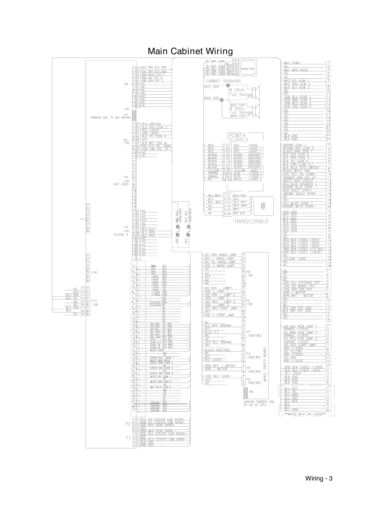
This page is a drawing, shown as the original scan.
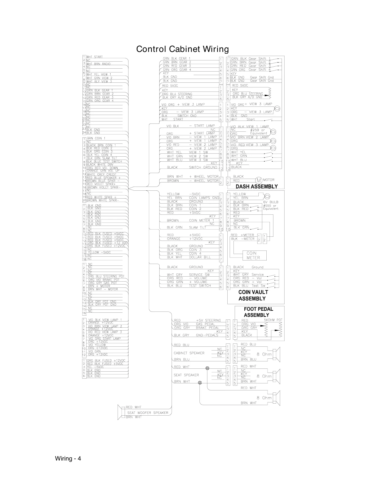
This page is a drawing, shown as the original scan.
Wiring - 5
Power Wiring Diagram
fon
AC POWER CORD
NY 100 Power Cot 580-1927100
POWER SWITCH
BLKRED (> _BLKYEL_ HOT | ___ | BLACK LINE SRN EL neuen ~< ware
WHT RED.
Power Inlet
Mounting Plate
10.PIN ‘COMMON BLOCK BLACK Lack [BLACK es BLACK 2
BLACK BLACK WHITE To Seat Speaker Connection on Main Hames
“Transformer BLUBLK —_36Vrms
BLUE BLU WHT WHT BRN WHITE WHT BLK
BLACK NC WHITE O6¢ BLACK crNyeL VIDEO WHITE MONITOR:
O6¢ S| BLACK GRNYEL | POWER WHITE SUPPLY 2FT IDC Power Cable
H-20353 LIGHT. FIXTURE For optional Dollar Validator, et To Seat Speaker Cable In Seat Assembly TRANSFORMER
CPU Board LED Indicator Status Chart
| DESIGNATION | LOCATION | FUNCTION | COLOR | STATE | MEANING | ||
| LED6 | Bottom Center | Diagnostic | Green | Off | Abnormal Game Play |
On Abnormal Game Play
Blinking Signals Normal Game Play
| LED 5 | Bottom Center | vO | Green | Off | PIC Recognized |
On PIC Not Recognized
| LED 4 | Bottom Center | Sound | Orange | Off | Abnormal Operation |
On Abnormal Operation
Blinking Signals Normal Operation
| LED 3 | Bottom Center | Power | Red | Off | Power Not Received |
On Signals Normal Operation
Blinking Abnormal Power Reception
H-Bridge Board LED Indicator Status Chart If Status LED Flashes... | Check to Make Sure... tor 10 times The motor’s power connector is connected. The left encoder is connected. 2 times The motor’s power connector is connected. The right encoder is connected. 3 times The left micro switch is connected. The left micro switch is not stuck. 4 times The right micro switch is connected. The right micro switch is not stuck. 5 times The left encoder is connected. 6 times The right encoder is connected. 7 times The left motor’s power connections are not reversed. 8 times The right motor’s power connections are not reversed. 9 times The fuse isn’t blown. The 48V power supply connection is attached to the board.
CPU DIP Switch 1 Settings Dedicated OFF
| Function | swi | sw2 | sws3 | sw4 | SW5 | swe | __SW7__ | SW8 |
Kit ON
Motion Disabled OFF Motion Enabled ON Stand Up Style Cabinet OFF Sit Down Style Cabinet ON Wheel Invert Disabled OFF Wheel Invert Enabled ON Unused OFF ON Link Disabled OFF Link Enabled ON Linking I.D. Number Master (Game Number 1) OFF | OFF
| Slave (Game Number 2) | ON | OFF |
| Slave (Game Number 3) | OFF | ON |
| Slave (Game Number 4) | ON | ON |
Wiring - 6
CPU DIP Switch 2 Settings
DIP Switch 2 Settings SWi | SW2 | SW3 | SW4 | SW5 | SW6 | SW7 _| SWS COUNTRY CODE USA OFF* | OFF* | OFF* | OFF* | OFF*
| GERMANY | ON_| | OFF | OFF | OFF | OFF | |||
| FRANCE | OFF | [_ON | |_OFF | |_OFF | [OFF |
| CANADA | ON | [ON | OFF | OFF | OFF |
SWITZERLAND OFF | OFF | ON | OFF | OFF ITALY ON | OFF | ON | OFF | OFF
| UK | OFF | [ON | ON | OFF | OFF |
| SPAIN | ON | [ON | ON | OFF | OFF |
AUSTRALIA OFF | OFF | OFF | ON | OFF JAPAN ON | OFF | OFF | ON | OFF
| TAIWAN | OFF | [ON | OFF | ON | OFF |
| AUSTRIA | ON | [ON | OFF | ON | OFF |
| BELGIUM | OFF | [OFF | ON | ON | OFF |
SWEDEN OFF | OFF | OFF | OFF | ON
| FINLAND | ON_| | OFF | OFF | OFF | ON |
| NETHERLANDS | OFF | _[_ON | OFF | OFF | ON |
| NORWAY | ON | [ON | OFF | OFF | ON |
DENMARK OFF | OFF | ON | OFF | ON
| HUNGARY | ON | [OFF | [ON | OFF | ON |
| GENERAL | ON | [ON | ON | OFF | ON | |
| USAT/IGERT/FRI/SPNT/AUSTRIAT/GENT | OFF__[ | OFF | |
| USA3/GER1/FR1/SPN1/AUSTRIA1/GENS | ON__| | OFF | |
| USA7/GER1/FR1/SPN1/AUSTRIA1/GENS5 | OFF | [ON | |
| USA8/GER1/FR1/SPN1/AUSTRIA1/GEN7 | ON | ON | |
| CANt/SWIT/ITL1/UK 1/JPN1/TWN1/BLGN1 | OFF__[ | OFF | |
| CAN2/SWI2/ITL2/UK2/JPN2/TWN2/BLGN2 | ON | [OFF | |
| CAN3/SWIS/ITL3/UK3/JPN3/TWN3/BLGN3 | OFF_[ | ON | |
| NTHRLDS1/FNLD1/NRWY1/DNMK1/HUN1 | OFF__[ | OFF | |
| NTHRLDS2 | ON | [OFF |
- Denotes default setting. Switches 1 through 5 select country. Switches 6 and 7 are used to select one of four modes for each country.
NOTES ON COINAGE: There are many ways to select the type and quantity of currency recognized by the game machine.
- The most common coin combinations for several countries are pre-programmed and can be selected from the table when Standard Pricing is activated (see Game Adjustments).
- DIP Switch settings may be changed with the power switched on. Set any switch and then observe the screen to verify that the desired selection is enabled. NOTE: If CMOS Coin Settings are active, switch settings for an individual Country will have no effect.
- Some European countries may accept currency used in other countries. The most popular coinage settings are listed beneath ‘Other’ in the Standard Pricing Table.
- Alternate settings are listed beneath ‘General’ in the Standard Pricing Table.
Wiring - 7
NOTES
Wiring - 8
CRUIS’N EXOTICA
CHAPTER
SIX
TROUBLESHOOTING
CN LN
@ Before servicing electronics, turn off AC power to the VGM. Wait for capacitors to discharge.
¢@ Before touching or handling electronic assemblies, discharge static electricity on your body. To discharge static, begin by connecting the line cord to a properly grounded outlet, but do not turn on the power! Next, touch the safety ground stud of the power supply chassis.
Store electronic assemblies in an anti-static area. Use anti-static bags to store or transport circuit boards. Transport the hard drive in original shipping container.
# Do not remove or connect electronic assemblies when power to cabinet is switched on. Otherwise, you'll damage electronic assemblies and void the warranty.
@ Replace ground wires, shields, safety covers, etc. upon completion of maintenance or service. Install and firmly tighten all ground and mounting screws.
Coin Mechanism and Pricing Troubleshooting Table
SYMPTOM
- Video Game Machine (VGM) accepts currency or tokens, but number of credits per coin or bill is incorrect. CAUSE
Improper settings at Pricing Menu REQUIRED ACTION
Press and hold TEST MODE switch inside coin door to enter Menu System. Select SWITCH TEST from Diagnostics menu. Conduct test to confirm operation of game switches. Select either the STANDARD or CUSTOM PRICING MENU from Game Adjustments Menu. Verify units and credits are set correctly.
Faulty wiring Confirm cabinet wiring is correct for this game. Assure coin meter and coin switches connect properly to control input wires.
- — VGM will not accept currency or tokens.
+ VGM will not enter play mode.
- Audio and video are present. Improper currency Unlock and open cash door. Empty cash box and inspect revenue for counterfeit currency. Check vault. Remove any items that block path from mechanism.
Faulty coin mechanism RON Unlock and open coin door. Check each mechanism for proper mounting. Remove mechanism. Clear currency path. Reinstall mechanism and close latch.
Tilted coin mechanism or game Verify mechanism is level after doors close. Repair or replace coin door if it is bent or damaged. If necessary, adjust cabinet leg levelers to keep mechanisms level.
- — Coin indicators do not light Burned-out bulb Burned-out bulbs may appear white or darkened. Check continuity with digital voltmeter. Replace burned-out bulb with an identically rated part.
Open fuse circuit Check fuse continuity with digital voltmeter. If fuse is blown, replace fuse with an identically rated part. If fuse isn’t blown, check wiring.
Troubleshooting - 2
Coin Switch and Meter Wiring
FACTORY STANDARD
| COIN SWITCH 1 | JAMMA PIN 16 | JAMMA PIN 8 |
COIN
| COIN SWITCH 2 | AMMA PINT | || | METER | y |
| COIN SWITCH | JAMMA GROUND | JAMMA *5VOLTS |
‘COMMON
OPTIONAL WIRING
| COIN SWITCH 1 | JAMMA PIN 16 | JAMMA PIN 8 |
COIN SWITCH 2
| COIN SWITCH | JAMMA GROUND | JAMMA +5VOLTS |
COMMON
INCORRECT WIRING
Aconnection between JAMMA coin input pins will cause twice the desired credits for each coin inserted. Acoin meter with a defective or missing diode may eventually damage driver circuits on the CPU Board.
| COIN SWITCH 1 | JAMMA PIN 16 | JAMMA PIN 8 |
COIN
GOIN SWITCH 2 JAMMA PINT 5 || METER
| ‘COIN SWITCH | JAMMA GROUND | JAMMA +5VOLTS |
COMMON
Troubleshooting - 3
Startup Troubleshooting Table
SYMPTOM
does not start.
non-functional.
- No audio
- — No illumination
- No video display
Troubleshooting - 4 + VGM appears completely CAUSE
- Video Game Machine (VGM) | Power problem REQUIRED ACTION
Check power is switched on. Make sure fans are turning. If not: Is the power supply connected to its power cable? Is power supply turned on? Plug cord into AC power outlet. Verify presence of AC line voltage.
Improper line voltage switch setting Turn off power. Unplug AC line cord. Check line voltage switch. If necessary, set it to agree with local AC line voltage. Retest game.
Open fuse Turn off power. Examine AC fuse on power chassis. Examine DC fuses on cabinet wall or electronic equipment shelf. Replace faulty fuses with identically rated parts. Turn on game power. If fuse opens again, check DC wiring harness and connectors.
Faulty wiring Remove line cord. Test line cord, power plug, and IEC connector for breaks or damage. Verify continuity of each wire in cord. Install cord on power chassis. Press connector firmly to seat it. Assure that cabinet wiring harness connectors fully seat in corresponding power supply and board connectors. Inspect wiring for breaks or damage.
Location of Power Supply and Line Cord
Startup Troubleshooting, continued
SYMPTOM
appears non-functional.
+ Currency acceptor price indicator is illuminated.
- Video Game Machine (VGM) CAUSE
Power problem REQUIRED ACTION
Inspect circuit boards under low-light conditions. The LED’s glow and the fan turns when Processor circuits receive voltage and indicate presence of DC from power supply. However, voltages or signals may not be normal. Turn on power. Set the digital voltmeter to the 20-volt DC setting and measure DC voltages at power connector pins. Adjust the +5V source if necessary. Refer to the Cabinet Wiring Diagram for specific wiring information and voltage limits. Set the digital voltmeter to the 2-volt AC setting and measure DC voltages at power connector pins. Any reading here indicates that supply voltages are unstable and may contain ripple or noise.
Faulty wiring Turn off power. Check wiring harness connectors attach and fully seat onto mating board connectors. Verify harness connects to CPU Board. Check other connectors in same way.
Improper DIP switch settings Check DIP switch settings.
Faulty circuit boards Run power-up self-test sequence. Note errors or failures during test. Compare LED's with LED indicator status charts. Note discrepancies. Press and hold TEST MODE switch inside coin door to enter Menu System. Select MONITOR TEST from Diagnostics Menu. Conduct test to confirm operation of each screen used in the game.
Typical Front View of Coin Door
Troubleshooting - 5
Startup Troubleshooting, continued
SYMPTOM
- Video Game Machine (VGM) does not start.
+ VGM accepts currency or tokens.
- Audio and video are present. CAUSE
Faulty coin mechanism REQUIRED ACTION
Unlock and open coin door. Check each currency acceptor to assure proper mounting. Verify each release latch is closed and locked. Test mechanism with good and bad coins to see if mechanism accepts and rejects currency correctly. Inspect to see if external acceptor indicators (Pricing, Flashing Arrows, etc.) are lit. Verify each acceptor operates properly by placing it in working game. Replace bad parts.
Faulty switches Press and hold the TEST MODE switch inside coin door to enter Menu System. Select SWITCH TESTS from the Diagnostics Menu. Conduct test to confirm operation of each switch. Assure no loose parts or wires are caught in switch contacts. Check for continuity in each suspect switch connection (Common to Normally Open or Common to Normally Closed). Replace faulty switches (bent levers, broken actuators, etc.).
Faulty wiring Assure no wires are caught in hinges, latches or switch contacts. Check wiring continuity from circuit board connectors to acceptors.
Troubleshooting - 6 Interior View of Coin Door
Linking Problem Troubleshooting Table
SYMPTOM
- — Cannot connect multiple Video Game Machines (VGMs) together CAUSE
Faulty wiring REQUIRED ACTION
Do not extend linking cables supplied with VGM. Do not use standard telephone type couplers or wiring for linking.
Improper linking hardware Use required Fire Wire Cable. Array completion requires basic kit brackets and spacers.
- VGM does not recognize other players in linking operation
+ VGM functions normally by itself Improper settings Record any error messages that occur during self-test. From the Diagnostic Menu select DIP SWITCH TEST. Confirm the link is enabled. Be sure that each VGM has a unique ID number. Select LINKING TEST from the Diagnostic menu. Run tests for each linked VGM.
Power problem Verify the game electronics receive power.
Faulty wiring (3 or more VGMs) Check for cable continuity from game electronics on VGM to the other game electronics. Assure no loose wires are caught in hinges, doors or under cabinet. Verify linking cable connects to CPU Board for each game. Verify each linking cable operates properly by placing it in working game.
- Some Video Game Machines (VGMs) in group link properly, while others do not Wrong software version Verify all linked VGMs use same version of software. Error message “VERSION MISMATCH’ will appear if you try to link different versions. Contact your distributor.
Faulty wiring (2 VGMs) Insert only the supplied Fire Wire linking cable to connect VGMs. Verify each linking cable operates properly by placing it in a working link between two VGMs.
Faulty wiring (3 or more VGMs) Separate communications wiring from other wiring. Wires that must cross can only cross at right angles to limit noise pickup.
Troubleshooting - 7
Player Control Troubleshooting Table
SYMPTOM CAUSE REQUIRED ACTION
| * — Intermittent or completely | Faulty switches or | 1. | Press and hold TEST MODE switch inside coin |
| non-functional player | lamps | door to enter Menu System. Select SWITCH |
controls TEST from Diagnostic Menu. Conduct tests to confirm switch operation.
| * | Video Game Machine (VGM) | 2. | Press and hold TEST MODE switch inside coin |
starts normally. door to enter Menu System. Select LAMP TEST from Diagnostic Menu. Conduct tests to confirm lamp operation.
- Check for loose parts or wires caught in switch contacts.
- Check continuity at each switch connection (Common to Normally Open or Common to Normally Closed).
- Verify player control operates properly by placing it in working VGM.
- Verify light bulbs used for dashboard switches are type specified in parts listing. Other types will light, but may produce too much heat. Excess heat may cause switches to bind.
| Faulty switch wiring | 1. | Check for wires caught in door hinges, latches, |
or switch contacts.
- Verify harness connectors are attached and fully seated.
- Assure control switches connect properly to control input wires.
- Check cabinet wiring is correct for this VGM.
| * — Steering pulls to one side | Faulty Wheel Driver | Find power amp on Wheel Driver Board's large |
Board heatsink. Test and replace bad part or board.
| * | No wheel feedback | Improperly set | 1. | Select | STEERING | WHEEL | TEST | on | the |
feedback Diagnostics Menu.
| * — Steering aims vehicle as | 2. | Set feedback to match player requirements. |
expected Maximum force may be too extreme for very young or inexperienced customers.
| Faulty circuit | 1. | Examine fuses and cables on Wheel Driver |
Board.
- Check cables and wiring between CPU Board, wheel driver and motor.
- Check resistance of motor series resistors.
- Replace bad parts.
| Faulty motor | 1. | Turn off power. Open dashboard. | Support |
steering wheel and remove outer mounting screws.
- Remove metal shield (if VGM has one) over motor.
- Unscrew caps.
- Inspect motor brushes. Replace worn parts.
Troubleshooting - 8
Player Control Troubleshooting, continued
SYMPTOM
- — Sloppy, unpredictable or ineffective steering
- Video is present
- Video Game Machine (VGM) operates normally CAUSE
Blocked or faulty fan REQUIRED ACTION
Fan located on power supply functions as an exhaust fan. With power on, check airflow near each fan to assure that nothing blocks airflow.
Faulty mechanical parts Turn off power. Open dashboard. Support steering wheel and remove outer mounting screws. Remove metal shield (if VGM has one) over motor. Inspect for faulty or worn belts, bearings, couplings, gears, etc.
Faulty Wheel Driver Board Inspect Wheel Driver Board under low-light conditions. To indicate presence of AC from the transformer the LED’s glow when voltage is received. However, voltages or signals may not be normal. Examine fuses and cables on Wheel Driver Board. Replace bad fuses. Use digital voltmeter to verify AC voltage between each fuse holder and ground. You should measure approximately 25V. See Wiring Diagram. Use the 20-VAC setting on digital voltmeter to measure DC voltage at motor. Do not move steering wheel, drive belt, or motor while making this measurement. Any reading _ indicates unstable supply that may contain ripple or noise. Select the STEERING WHEEL TEST from the Diagnostic Menu. Follow on-screen instructions to verify operation of the wheel motor and steering position sensor. Verify proper operation of Wheel Driver Board by placing it in working VGM.
Loose or worn drive belt Turn off power. Open dashboard. Support steering wheel and remove outer mounting screws. Remove metal shield (if VGM has one) over motor. Inspect for faulty or worn belts, bearings, couplings, gears, etc. Refer to the Service section for complete instructions. If drive belt isn’t worn or damaged, check its tightness.
+ Inability to make a transmission selection.
- Video Game Machine (VGM) operates normally. Improper DIP Switch setting(s) From the Diagnostics Menu, choose DIP SWITCH TEST. Make sure DIP 1, SW 1 is set to the OFF position.
Troubleshooting - 9
TENSION BOLT
How to Adjust Belt Tightness
yoRADIO BUTTON
4—SPEED SHIFTER
Player Panel Controls
Troubleshooting - 10
Video Troubleshooting Table
SYMPTOM
+ Monitor appears nonfunctional
- — Audio is present
- Video Game Machine (VGM) controls operate normally CAUSE
Power problem REQUIRED ACTION
Verify connection of AC Power to video monitor. Inspect neck of CRT in dim light. Glowing filament near CRT base confirms monitor circuits receive power. However, voltages or signals may not be normal.
Faulty wiring Turn off game power. Verify that video signal and Remote Adjustment Board connectors seat properly on Video Monitor Board. Assure that no wires are caught on chassis or mounting brackets.
Improper monitor adjustments Check BRIGHTNESS (intensity) and CONTRAST are set above their minimum levels.
Faulty monitor circuitry Examine AC line fuse on Video Monitor Board. If fuse is faulty, replace it with an identically rated fuse. If the fuse is good, verify video monitor operates correctly by placing it in a working VGM. If monitor is bad; Check monitor power supply. If the power supply is good, Check monitor horizontal output transistor and related circuitry.
- Graphic images from game do not appear
- No audio
- Power-up self-test runs Improper components Verify circuit boards are correct for this game. Labels on each board record manufacturers’ name, assembly number and hardware version. Verify ROM instruction set is correct for this game. Game set includes more than one ROM. Label on each ROM records assembly number and software version.
Faulty Circuit Board Allow game to load normally. Note and record any error messages that occur during self-test. Press and hold TEST MODE switch inside coin door to enter Menu System. Select Diagnostic Menu from the Main Menu. Then select CPU BOARD TEST. Conduct this test to check operation of critical components. Turn off power. Inspect CPU Board to ensure JAMMA cable connector is fully seated onto the mating edge connector of the CPU. Check all other cable connectors for correct alignment and continuity. Compare activity of LED’s on CPU with the CPU Indicator Chart.
Power Problems Turn on Power. Use 20-volt DC setting on digital voltmeter to measure DC voltages present at Power connector pins. Verify +5V source if it is adjustable. Refer to Cabinet Wiring Diagram for specific wiring information and voltage limits. Use 2-Volt AC setting on digital voltmeter to measure DC voltages at Power Connector pins. Any reading indicates the supply voltages are unstable and may contain ripple or noise.
Troubleshooting - 11
Typical Cutaway Rear View
Troubleshooting - 12
Video Troubleshooting, continued
SYMPTOM
- White areas at screen edges appear tinged with color
- Dots at screen edges appear ovoid or cylindrical CAUSE
Picture tube dynamic convergence is out of alignment REQUIRED ACTION
Have service bureau dynamically re-converge monitor. This procedure requires removing and repositioning yoke. Service bureau must follow instructions from monitor manufacturer.
+ Video images tear or roll, or have black bar down middle of screen Faulty wiring
| Check | connectors | and | cables | for | wiring |
continuity. Video cables connect circuit boards to video monitor. Assure connection of all cabinet ground wires, especially at video monitor chassis.
Faulty monitor circuitry Verify video monitor operates correctly by connecting it to working Video Game Machine (VGM). Assure video monitor is correct type for this game. Video monitors with wrong resolution can’t lock sync.
Improper sync signals Check to see if Video Board puts out type of sync that your monitor requires. Verify jumpers are set correctly for monitor.
Electromagnetic fields
| Move | cabinet | far | away | from | machines, |
appliances, or competitors’ video games.
- — Missing colors Faulty wiring
| Check | connectors | and | cables | for | wiring |
continuity from circuit boards to video monitor.
Faulty monitor color drive circuitry Verify video monitor operates correctly by connecting it to working Video Game Machine (VGM).
- — One color is dimmer or brighter than others
+ | Whites appear tinted everywhere on screen Maladjusted color bias pots BONS
Oa Turn on Video Game Machine (VGM). From Diagnostic Menu select MONITOR TEST. Watch Color Bars screen in mirror. Adjust three bias pots for best colors. (Most monitor neck boards include these pots.) Check White Screen. Touch up controls. If whites still seem tinted, have service bureau rejuvenate picture tube.
- — Picture is dim or faded Maladjusted BRIGHTNESS pot or subnormal picture tube emission From Diagnostic Menu select MONITOR TEST. Watch Color Bars screen. Adjust BRIGHTNESS and CONTRAST pots for greatest number of grays. You'll find these pots on Monitor Remote Control Board, behind coin door. If pots have no effect, have service bureau rejuvenate picture tube.
Troubleshooting - 13
SYMPTOM
Picture is too narrow Video Troubleshooting, continued
CAUSE
Maladjusted WIDTH pot REQUIRED ACTION
From Diagnostic Menu select MONITOR TEST.
| Watch | Crosshatch | Screen | while | adjusting |
WIDTH pot for best picture. You'll find this pot on Monitor Remote Control Board, behind coin door.
Picture is too short Maladjusted HEIGHT pot or damaged vertical circuit From Diagnostic Menu select MONITOR TEST.
| Watch | Crosshatch | Screen | while | adjusting |
HEIGHT pot for best picture. You'll find this pot on Monitor Remote Control Board, behind coin door. If pot has no effect, service vertical output circuit.
Picture seems shifted to one side Maladjusted HORIZONTAL POSITION pot From Diagnostic Menu select MONITOR TEST.
| Watch | Crosshatch | Screen | while | adjusting |
HORIZONTAL POSITION pot for best picture. You'll find this pot on Monitor Remote Control Board, behind coin door.
Keystone-shaped picture Shorted turns in yoke Substitute working yoke. Have service bureau converge monitor. Retest monitor.
Blotches of color appear on screen Picture tube aperture mask is magnetized Demagnetize monitor with external degaussing coil. Take care not to magnetize neighboring games. Monitor may be left on or off during this procedure.
White areas in center of screen appear tinged with color
Object edges have fringe of one or more colors Picture tube purity or static convergence is out of alignment Turn on Video Game Machine (VGM). Press and hold TEST MODE to enter Menu System. Select Diagnostic Menu from the Main Menu. Select MONITOR TEST. Perform tests for Crosshatch, Red, Green and Blue screens to find clearest display of problem. Display screen with the most severe problem. Display Crosshatch Screen. Locate purity and static convergence ring magnets on back of monitor neck. Watch screen in mirror. Adjust magnets to minimize problem. Follow instructions from monitor manufacturer. Display Crosshatch Screen. Touch up adjustments while watching screen in mirror.
Troubleshooting - 14
Audio Troubleshooting Table
SYMPTOM
No audio
Video is present
Video Game Machine (VGM) appears to operate normally CAUSE
Improper volume setting REQUIRED ACTION
Press and hold TEST MODE switch inside coin door to enter Menu System. Select VOLUME MENU from the Main Menu. Make sure the Attract Music is on (enabled). Verify all volume levels are set well above zero. If necessary, change levels to make game audible.
Faulty wiring Turn off power. Assure wiring harness connectors attach and fully seat onto mating board connectors. Verify harness connects to CPU Board. Check audio cable connectors in same way.
Faulty or obstructed speaker Remove grilles and inspect speakers. Free speaker cones, terminals, mounting screws and magnets of loose parts or wires.
Faulty Audio Board Verify proper operation of Audio Board by placing it in a working VGM.
Power Problems Use 20-volt DC setting on digital voltmeter to measure DC voltages present at Power connector pins. Verify +5V, -5V and +12V sources. Refer to Cabinet Wiring Diagram for specific wiring information and voltage limits.
Audio is distorted, muffled or has missing frequencies. Faulty or improper speaker Turn off power. Remove grilles and check speakers. Verify that speakers are full range (100 to 10,000 Hz response) and rated for at least 20 watts. Woofers must be rated for at least 40 watts. Verify proper speaker operation by placing speaker in question in a working VGM.
Faulty wiring Multiple-speaker installations: Check for reversed wires at one speaker. Weak or low frequencies and thin or hollow sound quality are symptom of incorrectly phased speakers. Sound tests may not detect this condition, but you can hear it during operation.
Improper Setting Press and hold TEST MODE switch inside coin door to enter Menu System. Select SOUND TEST from Diagnostics Menu. Increase volume as required. This test will verify some audio circuit functions.
Troubleshooting - 15
Audio Problems, continued
SYMPTOM
Dead sound channel CAUSE
Faulty speaker REQUIRED ACTION
From Diagnostics Menu, choose SOUND TEST. Recheck speakers with audio signals provided by test. Verify proper speaker operation by connecting speaker in question to working Video Game Machine (VGM).
Faulty circuit board Run power-up self-test sequence. Note errors found during tests. Compare CPU Board LED’s with LED Indicator Status Charts. Note discrepancies.
Constant low hum from all speakers. Faulty wiring Check cabinet wiring is correct. Verify cabinet wiring provides separate wires (not common return) for each speaker. Check connection of all cabinet ground wires.
Faulty power supply Use 2-Volt AC setting on digital voltmeter to measure voltages at speaker terminals. Any reading indicates unstable supply that may contain ripple or noise.
Troubleshooting - 16
Motion Seat Troubleshooting
SYMPTOM CAUSE REQUIRED ACTION
| + | VGM operates normally | Power Problem | 1. | Turn on Power. Use 20-volt DC setting on digital |
voltmeter to measure DC voltages present at
| * | Motion seat movement is | Power connector pins. Verify +5V source if it is |
intermittent or non-functional adjustable. Refer to Cabinet Wiring Diagram for specific wiring information and voltage limits.
| + | Error message NO MOTION | 2. | Use 2-Volt AC setting on digital voltmeter to |
DETECTED appears on measure DC voltages at Power Connector pins. screen. Any reading indicates the supply voltages are unstable and may contain ripple or noise.
| Mechanical Failure | 1. | From Diagnostics Menu select MOTION TEST. |
Conduct test and listen for the motor’s micro switch to activate.
- Check interlock switch located inside the seat pedestal base for proper operation.
- Remove the motors and check for worn brushes.
- Check for encoder failure.
| Faulty Wiring | 1. | Check to make sure data cable, serial cable and |
DC power harness are connected.
- Check for reversed power connection on motor(s). From Diagnostics Menu, select MOTION TEST. Conduct test to confirm operation.
| Faulty circuit board | 1. | Run power-up self-test sequence. Note errors |
found during test(s). Compare H-Bridge Board LED’s with the LED Indicator Status Chart. Note discrepancies.
- Run power-up self-test sequence. Note errors found during test(s). Compare CPU Board LED’s with the LED Indicator Status Chart. Note discrepancies.
| + | VGM operates normally | Improper DIP Switch | 1. | From Diagnostics Menu, choose DIP SWITCH |
setting(s) TEST. Make sure the DIP’s are set properly for
| + | Motion seat movement is | motion. |
intermittent or non-functional | * Error message will not appear on screen if DIP switch is used to turn off motion.
Troubleshooting - 17
Miscellaneous Problem Troubleshooting Table
SYMPTOM
- Marquee lamp is intermittent or non-functional
- Video Game Machine (VGM) Starts and plays normally CAUSE
Faulty fluorescent tube REQUIRED ACTION
Remove fluorescent tube from sockets. If you find cracks or darkened ends, install new lamp. Clean tube. Check continuity of both fluorescent tube filaments. Check lamp ballast is rated for local AC line voltage and frequency. Verify fluorescent tube operates by placing it in working VGM.
Faulty lamp fixture Verify lamp pins make good connection with socket contacts. Check the ballast and/or starter
Faulty wiring Measure fluorescent lamp AC voltages. Check wiring and connector continuity from AC power chassis to lamp assembly.
+ VGM operates normally
- Cabinet becomes warm after several hours of use Obstructed fan Check bottom and rear of cabinet for blocked airflow. Move VGM away from sources of heat. Turn off power. Remove dust from vent holes with high-power vacuum cleaner.
Faulty wiring Check fan wiring and connectors.
Faulty fan Check operation of all fans.
- Error messages appear on screen
Troubleshooting - 18 Faulty hardware Check any assembly (RAM, ROM, Battery, etc.) identified in error messages. Call your authorized distributor for help with unresolved screen messages.
WARNINGS & NOTICES
- Substitute parts or modifications may void EMC directive or FCC type acceptance.
- This game is protected by federal copyright, trademark and patent laws. Unauthorized modifications may be illegal under federal law. This also applies to MIDWAY logos, designs, publications and assemblies. Moreover, facsimiles of MIDWAY equipment (or any feature thereof) may be illegal under federal law, regardless of whether or not such facsimiles are manufactured with MIDWAY components.
If you or anyone in your family has experienced symptoms linked to an epileptic condition (e.g. seizures or loss of awareness), immediately consult your physician before using any video games.
We recommend that parents observe their children while they play video games. If you or your child experience the following symptoms: dizziness, altered vision, eye or muscle twitching, involuntary movements, loss of awareness, disorientation, or convulsions, DISCONTINUE USE IMMEDIATELY and consult your physician.
COPYRIGHT & TRADEMARK NOTICE You may not reproduce any part of this publication by mechanical, photographic, or electronic means. You may not produce phonograph recordings of this document. You may not transmit this publication or otherwise copy it for public or private us, without permission from the publisher.
CRUIS'N EXOTICA is a trademark of Nintendo. © 1999 Midway/Nintendo. All rights reserved. Manufactured and sold by Midway Amusement Games, LLC. under license. HUMVEE®, HUMMER®, and the VEHICLE GRILL DESIGN are registered trademarks of AM General Corporation. © AM GENERAL CORP. 1999 all rights reserved. FORD TRADEMARKS USED UNDER LICENSE FROM FORD MOTOR COMPANY. CHEVROLET, CHEVY, CORVETTE (1963, 1981 and 1998 models) and VETTE are General Motors Trademarks used under license to Midway Amusement Games, LLC. JEEP and the JEEP grille design, DODGE and PLYMOUTH are registered trademarks of DaimlerChrysler Corporation and are used under license. © DaimlerChrysler Corporation.
For service: Call your authorized MIDWAY AMUSEMENT GAMES, LLC Distributor.
When MIDWAY ships a game, it is in compliance with FCC regulations. The FCC label on your cabinet is proof. If this label is missing or damaged, legal repercussions to the owner or distributor of the game may result. If your game does not have an FCC label, contact MIDWAY immediately.
MIDWAY AMUSMENT GAMES, LLC 3401 N. CALIFORNIA AVE. CHICAGO, ILLINOIS 60618-5899 http:Avww.midway.com
Entire contents of this manual copyright © 2000 MIDWAY AMUSEMENT GAMES, LLC All Rights reserved.