005
005 (Sega, 1981) · Manual · 78 pages · 15 sections · original scan
Owner’s Manual
Manual Part No. 420-0692
oos*™
OPERATING INSTRUCTIONS
AND
SERVICE MANUAL
MANUFACTURED BY
TLX 910-335-1621
005 OWNER'S MANUAL
Copyright - 1982 by SEGA/Gremlin, All Rights Reserved
This page carries no recoverable text. It is a drawing or a photograph. See the original scan.
INTRODUCTION
005 is an electronics game that makes extensive use of digital
integrated circuitry and television monitor concepts. This manual is
intended for the use of the maintenance technician who possesses a
general working knowledge of solid state circuitry, microprocessor and
digital integrated circuitry, and video monitor concepts. Any individual
NOT knowledgeable in these areas SHOULD NOT attempt repair of the
electronic portions of the game, referring rather, to a competent
technician.
SEGA/Gremlin's G-80 system will make troubleshooting easy. Each
board has a separate function and most problems can immediately be
isolated to a single board. The individual boards contain less circuitry
than if they were combined on one or two boards. This results in faster
and easier servicing. The new G-80 card cage system provides for a self-
test feature (located on the CPU board) in addition to giving SEGA/Gremlin
more flexibility in designing new games compatible with the revolutionary
CONVERT-A-GAME Increased ROM capability and the addition of a quality
synthesis (in some games) means that new SEGA/Gremlin games will be more
exciting and certainly more profitable. Comments or questions about our
games are welcome, and should be directed to:
Technical Editor
SEGA/Gremlin 16250 Technology Drive San Diego, California 92127 TLX 910-355-1621 (714) 485-0910
Game Set-Up and Inspection
1.
a)
b)
c)
a) Inspection
Before plugging in your new game, inspect it closely to spot any possible
shipping damage. Check to ensure the graphics are in place, the monitor
is not damaged and that the overall cabinet is in good condition.
Open the coin mechanism door and inspect the inside of
the game electronics compartment. Be sure no components or connectors
have come loose. Proper connector fittings must be checked before game
power is applied. Check all related connectors for good contact.
Although disconnected connectors are easily spotted, poor contacts are
difficult to locate. The connectors should therefore be pushed in firmly
and then loosened to spot poor connections.
Are the fuses intact? There are five fuses (not counting the monitor
fuses which are detailed in the monitor manual for this game). One
fuse is located on the AC junction box. >The other four are on the power
supply PC board.
Voltage Selection
Before plugging in your game, make sure that the game voltage is correct
for your location. Locate the two leads from the AC junction box to
the power transformer. For 110 VAC, they should be connected to terminals
1 and 3 on the power transformer. For 100 VAC, connect 1 and 2, and for
220 VAC applications, they should be connected to 1 and 4.
You will also notice on the AC junction box that there is a safety
interlock switch. When the front panel is in place the switch is depressed -
and the game receives power. Removing the front panel, the switch returns
to its original position and the power is cut off from the game. For
servicing, this switch can be pulled out and power will be restored.
3. ‘Game Specifications
Power 100 VAC, 60 HZ (nominal), 150 watts max
110 VAC, 60 HZ (nominal), 150 watts max
220 VAC, 60 HZ (nominal), 150 watts max
Dimensions 25 1/2 inches wide x 30 1/4 inches depth
4.
a) (64.38 cm wide x 76.8 cm depth)
72 1/2 inches height (184.2 cm height)
The following notes are included in compliance with FCC rules:
energy and if not installed and used in accordance with the instruction
manual, may cause interference to radio communications. As temporarily
permitted by regulations, it has not been tested for compliance with the
limits for Class A computing devices purseant to Subpart J of Part 15 FCC
Rules, which are designed to provide reasonable protection against
interference in which case the user at his own expense will be required
to_take whatever measures may be required to correct the interference.
Miscellaneous
Never remove circuit board connections while power is on.
Never replace any components with anything other than exact replacement parts.
00 NOT replace fuses with anything other than the proper value. A blown fuse indicates an overload condition within the game. Replacing the fuse with a higher value can cause severe damage to internal components, if an overload occurs.
5. Control Panel Removal
With the door to the game electronics compartment open, reach under the control panel and flip the fasteners on both sides of the control panel. The panel will now swing outwards. Disconnect the control] panel harness, slide the spring-loaded pins on both sides and remove the control panel.
Front Plexiglass, Interior Graphics and Graphics Frame Removal The front plexiglass, which secures the interior graphics, is held in place by the control panel. Release the fasteners on the control panel and swing it down. Directly under the front plexiglass, you will notice the graphics frame piece. Grab it in the middle, and pull it from the game. The front plexiglass can now be easily removed by lifting it on the bottom slightly and pulling it outward. The interior graphics are now free to remove. You will also see the graphics frame, which must be removed when taking out the monitor. Simply grip two sides and carefully lift out.
Card Cage Removal If it is necessary to remove the card cage for servicing, first pull all the connectors. Then remove the three mounting screws located on the front bracket. The card cage can now be slipped out from under the rear bracket and removed from the game.
Logo Panel Removal Remove the front plexiglass, interior graphics and graphics frame as explained above. Logo panel removal is accomplished in one of two
ways. Underneath the logo panel, the presence of four mounting screws will dictate the removal of those screws, allowing the speaker board to swing, freeing the logo panel for removal. In the absence of the mounting screws, you will notice a sliding latch, underneath the logo panel and on either side of the speaker. Using a small flat-head screwdriver, slide those latches inward to release the speaker swing panel. Push up on the back portion of this panel, and the logo can
now be removed.
Monitor Removal
To remove the monitor for servicing or replacement, first open the
back panel on the cabinet and disconnect the leads to the monitor.
Then, remove the front bezel, interior graphics and spacer frame
as explained earlier. Underneath the monitor in the game electronics
compartment are four bolts securing the monitor in place. Remove
these, pull the monitor on either side and slide it out carefully.
005 GAME CONCEPT
Agent 005's mission: evade enemy guards, negotiate warehouses and
skating rinks to deliver attache cases to a waiting helicopter, which in
turn must engage in an aerial battle with parachute bombs, balloon bombs
and an enemy helicopter. Game play begins as 005 parachutes into the
scene and picks up an attache case. To make a run for the helicopter
straightaway is difficult and accumulates fewer points. His alternative
is to duck into either a warehouse or skating rink.
Armed with a stun gun to ward off pursuing guards, 005 can select
a building with either 1, 2 or no stun gun cannisters at the entrance.
Gas cannisters extend the stun gun's range and add more points. Fallen
guards can be passed by other guards, but not by 005. Once inside the building,
the scene changes to the interior of that building. In the skating rink, 005
must travel the rink's perimeter, luring the guards onto the ice to stun or
evade them. Caution must be exercised here, as 005 can change direction, but
cannot stop until he hits the edge of the rink. A successful rendezvous
with the helicopter completes that delivery and shifts the scene back to
005 parachuting in to pick up another brief case. Once having been in the
skating rink, only warehouses are there to enter, and conversely, if a
warehouse was first entered, only skating rinks are available. In later
rounds however, both skating rinks and warehouses are displayed. In the
warehouse, 005 moves cautiously in the dark, but is pursued once caught in
the beam of a guard's flashlight. Again, a helicopter waits to pick up
our hero as he makes his way out the far end.
Now in possession of two attache cases, 005 is pursued by an enemy
helicopter. Avoiding hedges, shrubbery, descending helicopter bombs, and
ascending balloon bombs, points are scored as 005 shoots balloon bombs,
shrubbery or the enemy helicopter. The game ends if 005 is caught, or his
helicopter is shot down a total of three times (operator selectable).
Scoring
Attache delivered to helicopter 10,000
Guard knocked out 200
Entering a building with:
No stun gas cannister 300
1 stun gas cannister 400
2 stun gas cannisters 500
Shooting down:
Shrubbery : 20
Balloon Bomb 200
Enemy helicopter 5,000+ (2,000 X no. of brief cases delivered)
005 OPTION SWITCH SETTINGS
OPTION SWITCH #1
Game Type 1 2 3 4 5 6 7
Upright x x x x x 0 x
Cocktail x x x x x c x
No. of men per game
6 x x x x x xX Q
5 x x x x x x c
4 x x x x x x 0
3 Xx x x x x Xx c
X = Not Used Q = Open C = Closed (Off) (On)
COIN/CREDIT OPTIONS
Coin/Credit
UEWN| FN UEN
FUN ‘coins/1 credit
coins/1 credit
coins/1 credit
coin/1 credit
coin/2 credits
coin/3 credits
coin/4 credits
coin/5 credits
coin/6 credits
coins/1 credit coins/2 credits coins/3 credits
coins/1 credit coins/3 credits
coin/1 credit coins/2 credits coins/3 credits coins/4 credits coins/6 credits
coin/1 credit coins/2 credits coins/3 credits coins/5 credits
1 coin/1 credit iS)
Wrwna
WN coins/3 credits
coin/2 credits coins/4 credits coins/6 credits coins/8 credits coins/11 credits
coin/2 credits coins/4 credits coins/6 credits coins/9 credits
= Not Used 0 = Open (Off) SWITCH #2
1 2
c c
c c
c c
c c
c 0
c 0
c 0
c 0
te) c
0 c
te) c
0 c
Q 0
te) 0
0 0
ie) 0
| 6 | 7 | 8 |
| c | c | c |
| c | c | te) |
| c | 0 | c |
| c | 0 | 0 |
| 0 | c | c |
| 0 | c | ie) |
| 0 | ie) | c |
| 0 | 0 | 0 |
| c | c | c |
| c | c | 0 |
| c | 0 | c |
| c | 0 | ie) |
| te) | c | c |
| 0 | c | o) |
| 0 | 0 | c |
| te) | 0 | 0 |
C = Closed (0n)
G-80 BLOCK
DIAGRAM
COMPOSITE SYNC
COMPOSITE SYNC
+ DENOTES CIRCUITRY CONTAINED IN VIC J0aF
G-80 Boards G-80 THEORY OF OPERATION
The G-d0 system consists of several boards that plug into a mother
board in a card cage system. This system simplifies repairs and cuts
down on interference from outside communications systems. The mother
board is crosswired to allow for the boards to be plugged-in in any
order.
a Ground
2 AlS
3 ALA
4 Al3
5 Al2
6 All
7 Alo
8 AQ
9 Ag
10 07
V1 D6
12 D5
13 DA
14 WAIT
15 INT
16 NMI
17 EXT SEL
18 MEMR
19 INPUT
20 RFSH
21 INTACK
22 +5V
23 +5V A
B Listed below are the bus pin assignments on the mother board:
Ground
AT
Ab
AS
Ak
A3
A2
Al
AO
D1
DO
RESET
EDGINT
EXT
OUT
MEMW
OUTPUT
MREQ
AC
+5V
+5V
| 24 | -5V | b | -5V |
| 25 | +12V | c | +12V |
| 26 | -12V | d | -12V |
27 e
| 28 | HALT | f | MI |
| 29 | /2 | h | * |
| 30 | * | j | * |
| 31 | SRC | k | * |
32 1
33 m
34 n
35 p
36 r
37 s
38 t
39 u
4o v
4] w
4a x
43 y
| 4k | Ground | z | Ground |
*For Development Purposes Only
- CPU Board
The CPU board is completely timed with the video board. But, for
testing purposes it contains its own clock circuit, powered by an
8.000 MHZ crystal. Pin 17 is the external clock select and is grounded
when the video board is plugged-in. When the external clock pulse
comes in through pin T, it goes directly to the CPU and the entire
CPU clock circuit is disabled. The WAIT signal, entering in at pin 14
is used to synchronize slower memory accessed by the CPU.
b) The NMI circuit, entering in at pin 16, contains a switch for activating
the built-in-self-test. The self-test system will be explained more
fully later.
When the edge interrupt circuit, entering at pin S, goes LO, it
triggers an interrupt in the CPU. The CPU stops whatever it is working
on, completes the activity required by the interrupt, and then returns to
the function it was performing prior to the interrupt. It is a negatively
triggered interrupt, which can be disabled by the CPU at any time.
The AC signal, entering in at pin Y, combines with RESET at pin R
and the input from the reset switch located on the operator panel to
reset the CPU. Disregard PANEL RESET at pin 30. This circuit is used
only for system development.
The CPU is a Z80A. A Z80A must always be used as the 280 is not
fast enough to run the G-80 system. U21 is an address bus controller.
Eight of the sixteen address lines pass through U2] before addressing
the RAMs and Eprom at U25. U25 contains the data for the self-test
and contains features common to all games, such as coin acceptance,
credit/coin handling, power-up sequence, player | or 2 recognition and
CPU initialization. U3 is an output port for the CPU and U4 is an input
port. Connector Pl, pins 24 through 40, shown on sheet 6 is not used.
UI5, located below U4 on the schematic, decodes memory select on the
CPU board. Sheet 7 contains the coin inputs, player inputs and inputs from
the operator panel. The coin circuitry contains ICs U6, U39 and UI16.
U9 is the input port for the coin switches and service switch. Player
inputs enter through connector Pl, pin 15 through 22.
SOUND BOARDS
A G-80 Sound Board contains the circuits needed to generate all
game sounds other than the speech. The Sound Board Circuits are
triggered through 8-bit latches, which are connected to the data bus.
c)
d)
e) The appropriate 8-bit code on the data bus is then latched to activate the
corresponding sound circuit. All Sound Board signals are mixed by an IC
op-amp, the output of which is amplified by the power amplifier. I!n
games containing a Speech Board, the Sound Board output is mixed with the
speech output on the Speech Board. The result of the mixed signals is then
amplified by the power amplifier to drive the speaker.
VIDEO BOARD
The video board contains a 15.468 MHZ crystal that generates the
timing signals for video generation. Because the video board contains
twice as many RAMs, it has more extensive graphics capability. Color
capability is greatly expanded because of a color RAM, U9, which allows
the program to create a wider variety of color schemes. There are 8 shades
of red, 8 shades of green and 4 shades of blue. The video board also contains
circuitry (U34, U35, U36, U38, U49 and U50) to make the picture "flip'' for
cocktail table models.
On the G-80 Video | Board is located the VIC Replacement Board. This
board is, in part, the equivalent circuit of the VIC chip. It is a simple
circuit consisting of a number of counters and multiplexers for generating
video timing and addressing video RAM.
EPROM Board
The EPROM board contains a relatively simple memory system. It can
hold up to 23 2716 EPROMs totalling 46K bytes of memory. U24 and U30 decode
all the EPROMs; U25 is the buffer IC to the data bus. In operation, any one
of the 23 EPROMs is selected by 5 CPU address lines.
POWER SUPPLY
The G~80 power supply incorporates all cf the voltages and audio power
amplification necessary to power any G-80 based video game. The major
differences between this and other Gremlin power supplies is that the
transformer (560-0055) is mounted separately from the PCB/heatsink/chassis
combination. This transformer is noticeably larger than previous units,
mainly because it has isolation windings for driving X-Y color monitor as
well as windings for a raster scan color monitor. There are multiple
primary taps available for using 100, 115, or 230 VAC as the input voltage.
Table 1 lists the ratings of the regulated DC voltages ( a standard
test load) as well as the ratings of the transformer's windings used to
drive the X-Y or raster scan monitor.
TABLE 1
Regulated DC Voltages
+5V @ 6A
-5V @ 1A
+12V @ 1A
-12V @ 1A
AC (monitor) Voltages
X-Y: 92 VCT (voltage center tap) @ 2A
Raster: 100 or 115 VAC @ 0.65A
Voltage Regulator Circuit Description
The +5 volt supply mainly consists of U1 and the TIP141. U1 is a 723
voltage regulator IC which contains a voltage reference, error amplifier,
series pass darlington transistor pair and a current limit transistor.
Potentiometer R31 (+5V ADJ) divides the 7.15 (NOM) reference to 5.0 volts
as the input to pin 5, the noninverting input of the 723's error amp. Pin
4, the inverting input, senses the output voltage. The internal error amp
maintains a voltage at U1 pin 10 which is higher than the 5.0V output by
an equal amount to the two VBE drops of the TIP141 (a high current
darlington) which acts as a current amplifier, and IR drop across R25.
Any change in the output voltage is sensed at pin 4 which causes the
error amp to drive pin 10 higher or lower in order to keep the output at
a steady 5.0V.
A "foldback"! current limiter circuit is composed of R25, R26, R32,
Q7 and the internal current limit transistor of U1.. This circuit allows
the regulator to operate normally until the load current increases to
the point where the voltage across the R32 reaches the value which starts
turning on the internal current limit transistor. This transistor reduces
the output current of the regulator to a fraction of the ''knee'' current when
the output is shorted to ground. This feature greatly reduces the power dissipated in the TIP14i when the output is accidently short circuited.
Capacitors C20 and C21 frequently compensate the regulator so it
won't oscillate and C17 filters high frequencies at the output. Q7
temperature compensates the current limit circuit. Temperature variations
of its emitter-base voltage closely match and cancel the base emitter
voltage of the internal current limit transistor, the knee current of
this regulator would now remain constant over wide temperature variations.
Audio Amplifier Circuit Description
The G-80 power supply has provisions for two power amplifiers. Only
one is used at present and the foreseeable future. The input signal
from the volume control is coupled to differencial pair Q2 and Q3 via
C5. Resistor R5 sets the input impedence 22K ohms. Resistor R6 sets a
current of approximately 2 ma for Q2 and Q3 to divide equally. The
voltage gain of Q2 is determined by its emitter current, R7, and the
impedence looking into Q1, the second stage of voltage gain. Resistor
R8 provides local negative feedback in the emitter of QI for increased
open loop linearity while C9 and Q1's voltage gain provide a dominate
pole open loop roll-off to ensure stability of the amplifier. Diodes
D4 and D5 provide a small amount of turn on bias for the TIP120 and
TIP125 darlington current amplifiers. Resistor R22 is bootstrapped
by C10 to make R22 look like a current source. This technique allows
maximum negative voltage swing for a symetrical output waveform at full
power. Local feedback in the output stage is provided by R14 and R15.
The overall voltage gain of the amplifier is set by the ratio of R9 and
R10. The actual value is:
7 4, 2 2K R10 1K
Capacitor C7 adds additional high frequency compensation and the + 1 + 23 or 27db
C8-R10 combination determines the low frequency roll-off point of -3db
at 16Hz. The C11-R17 combination provides feedback loop stability in the
event that a speacker is not connected. The maximum output is approximately
25 watts into 4 ohms and 15 watts into 8 ohms.
Adjustments
- Adjust R31 for 5.0V at the load. This compensates for wiring losses.
- Thére are no other adjustments. The tolerances are as follows:
-5V + 0.2V
+12V + 0.5V
-12V + 0.5V
This page carries no recoverable text. It is a drawing or a photograph. See the original scan.
Self - Test
This is a basic self-test sequence for any G-80 game.
Basic diagnostic test sequence:
CPU RAM
Maskable interrupts
First 1K of game ROM's
Video RAM and Hardware multiplier
Player start buttons
Display screen (visual)
All game ROM's
System input
Game controls
Sounds/Voice
Individualized diagnostics descriptions and procedures:
CPU RAM test - Test all the RAM's on the CPU card before proceeding,
the system needs to use this RAM for stack and variables during
other tests so if any locations are bad the processor will halt
(halt light on).
Maskable interrupts test - Video interrupt is enabled through the
output port bit and all maskable interrupts are enabled inside the
processor, the CPU then executes several HALT instructions to insure
that at least one edge-triggered interrupt has occured. If no
interrupts occur during the test the halt light will remain on
constant which is the same result as a bad CPU RAM. This ambiguity
can be eliminated by checking the vertical interrupt another way.
The system reset/power-up logic will also halt if the video interrupt
is not functioning.To try this, press the ''Reset!' switch.
c)
d)
e) First 1K of game ROM's test - The first IK of the first game ROM
will be checked for validity. If this portion of the first ROM
is bad the system will not be able to proceed because important
information defining parameters of the game are stored in this first
1K. If an error occurs during this validity check the CPU. It will
hand up and repeatedly flash the halt light.
Video RAM and Hardware multiplier test - The video RAM is tested
first in the event that it tests good then the hardware multiplier
is checked. If the video RAM is good the message ''All Video Ram Good''
appears. If a bad video RAM chip is found then the message ''Bad
Video RAM chip U'' appears on the screen along with the chip U number
(U#). Due to the fact that somtimes a bad video chip causes the
display to be useless, the system also flashes out the bad chips "'U#!'
on the halt light, over and over again seperating the "U#" with a
one second on=pulse. The hardware multiplier is used in the game to
multiply two 8-bit numbers together to form one 16-bit product.
This test performes a select group of multiplications, over 2000
in actuality, design to thoroughly exercise the process of multiplication
between the software and the hardware multiplier. The message ''Good"'
or ''Bad'' are the anly indications of functionality with respect to
this test.
Player start button test - One of the ''two game start'’ push buttons
on the front of the cabinet is very special. The ''one player start!’
button was designed by the system as a way to terminate the test that
is currently being run. The reason that these two buttons were tested
relatively early in the sequence was so that the remaining tests could
use one of them for a termination signal.
f) To be sure that these two buttons are functioning properly, check
it when it is untouched, the status indicated is ''0'' (for open switch
contact) and that when pushed or depressed momentarily the indicated
status is ''C'' (for closed switch contact) during the time the button
is down. This notation for switches being in the ''Open" or "Closed"
state, "'0'' or "'C'' will be used throughout the diagnostic sequence
whenever the status of a switch is being displayed on the screen.
Screen Test - This test is supplied by the game logic, external to
the "CPU ROM", to provide a visual indication of how well the display
screen is functioning. Depending on how the game hardware is set up,
XY or Raster, or what software version of the game you have, the
appearance of this test display may change. Usually there will be
some sort of pattern to test beam deflection and colors to check that
all electron guns are functioning.
All game ROM's test - The intent of this test was to insure the
integrity of all of the data in all of the game ROM's. When the ROM's
for a game were originally generated there was an logrithm performed
on each IK block of data. Each of these calculations, a form of CRC
(cyclic redundency check similar to a check sum), produces a 16-bit
word. These words are stored, along with a Gremlin part number, in
the first ROM. When this test is run all of these 16-bit CRC words
are re-generated and are compared to the known values stored in the
table in the first ROM. If one of these newly calculated values does
not match its corresponding stored value then the system kicks out an
error which amounts to the message ''Bad ROMs'' followed by one or
more bad part numbers of that ROM that was found in mis-match. If
all ROM's are good the system quickly proceeds on the next test.
h) System Inputs test - These inputs are refered to as ''System inputs"
simply because they control system functions, such as credit accumulation,
coinage options, game configuration, etc. The diagnostic user may
check to see that the coin switchs, service switch, and option ''DIP!
switches are functioning properly. The ''0pen'' and ''Closed'' switch
notation applies here as described earlier.
Game controls test'- The names of the controls that the game player
would use to control the action on the screen is what this test was
designed to check. Make sure that when hands are off of the controls
all of the switches are "Open''. When a particular control is twisted,
pushed, turned, or whatever, watch to see that the status of that
control, and only that particular control, changes to reflect the
action on the control panel.
Sounds/Voice test - The final phase displays each type of sound on
the screen accompanied by the actual audio sound. The final sequence
is Voice. The test runs through the entire vocabulary of the game.
a) Troubleshooting
The previous section described the basic sequence of the
G-80 self-test system. This section details how to use the
self-test in troubleshooting the G-80 card cage.
As in any troubleshooting procedure, we first want to
eliminate as many possibilities as we can. So, for the purpose
of this discussion, we'll assume that the power supply and
monitor have already been checked and perform properly. (For
monitor problems, check the monitor manual for your game. Power
supply troubleshooting will follow this descussion.) Now, we can
isolate the problem further by checking each of the G-80 boards.
Let's look at a typical check-out procedure for the boards.
CPU BOARD
Before we start our procedure for the CPU board, we can
eliminate two possible boards right away. These are the Sound
and Speech boards. By removing these boards first, we'll find
out two things immediately. 1) The Speech and Sound Baords are
probably good, if the original problem remains. 2) That either
the Speech or Sound Board, or both, are defective, if the
original problem clears up.
Doing this isolates the problem still further to just three
boards. That's a better place to start. Now, we can plug
the CPU Board into the extender board and insert it into any
slot on the mother board. This enables you to place any other
board in the top slot for easier access.
Now activate the G-80 self-test. Observe the red LED on the
CPU Board. If it lights and remains lit, this tells us that
one of the CPU scratch pad RAMs, U26-U29, is probably bad.
To find which one, replace them, one at a time and run the self-test
again each time. If the LED lights and flashes, this indicates
a problem somewhere on the CPU Board. Now we have to isolate further.
Begin by using an oscilloscope to check the following levels:
- RESET pin 26 of the Z80A should be high, or about 5 volts.
If it is low, the Z80A will lock up--trace the signal back to U30,
pin 13, U23, pins 1 and 2, and the rest of the reset circuit, UI2,
Q5 and Q6.
- Next, look at the C LOCK INPUT, pin 6 of the Z80A. On this pin
there must be a 4 MHZ clock signal that swings between 0 and 5 volts.
If it is anything else, check the clock circuit on the video board,
and follow it to the CPU Board through UI9 and UI18.
- Then, check for a high level on pins 24, 17 and 16 on the Z80A.
These are the WAIT, NMI and INT signals, respectively. If any are
low, trace the cause of this through the signal's respective circuit.
- Next, look at the outputs of U34, a 74LS244. These are pins
3, 5, 7, 9, etc., and if any are floating, suspect U34 as being
defective.
- Then, verify that the input signals on U36 and U38 are present
on the outputs of the chips. If any outputs are missing or floating, suspect U36 or U38.
- If the orginal problem was that the game would not coin-up,
check U6, pins 3 and Il, U39, pin 9, UI6, pin 12 and U7, pin 12 for
level changes when the coin switch is activated. Also, verify that
the coin counter advances when the switch is triggered on connector
Pl, pins 1 and 3. If any or all player control switches do not operate
the game, suspect U5.
These tests can be made quickly by running the self-test again and
observing the input port display. When a player or control switch
is activated, the display will change from ''0"' (open) to ''C'' (closed),
indicating a closed switch contact.
Up to this point, we've run a series of tests to check-out the
CPU Board. If the results prove good, our problem is more than likely
in either the Video or EPROM Board. Let's proceed to the Video
Board first.
VIDEO BOARD
First, run the self-test again to see if it reveals a bad video RAM.
The display indicates which RAM is defective. Replace it and re-
start the test. The memory should now be OK. If the test shows
another bad RAM, replace that RAM. If the test still indicates
another bad RAM, U33, a 7458283, could be defective. Replace it, and
run the test again. The memory should now pass. Verify that the
color RAM, U9, is OK by observing the color pattern at the end of
the self-test. If any colors are missing or the display is incorrect,
suspect U9, UI], U7 or U8.
On some G-80 Video Boards, you'll] see the VIC replacement board.
As was mentioned earlier, this board is, in part, the equivalent
circuit of the VIC chip. It is a simple circuit consisting of a
number of counters and multiplexers for generating video timing
and for addressing video RAM. When troubleshooting a video board
with the VIC Boards, be careful that the pins on the board do not
bend and that they make good contact with their socket. The 40-pin
socket may need to be replaced if no other problem is found on
either the VIC or Video Board.
To troubleshoot a Video Board with either a VIC chip or board,
verify first that all address lines to the VIC socket have active
signals present on pins 12, 13, 14, 23 and 29. All these signals
c) must be rapid clock pulses. Follow the outputs of the VIC chip
or board through U39, U40 and U38 to the address lines on the RAMs.
Again, these lines must be pulsing high and low.
Sometimes, the RAM self-test does not reveal a bad RAM, even though
the picture is still incorrect. To locate the defective RAM, ground
pin 14 of each RAM, the output pin, and observe the display. When
you ground the defective RAM's output, the picture wil] break up
even more in that part of the display that was originally distorted.
This usually indicates that this RAM is bad. Replace it and re-run
the self-test.
Suspect the VIC chip or board if the game has a vertical or horizontal
sync problem-- for example, if the picture rolls and adjusting the
monitor does not affect the display. Finally, it is improtant that
the following ICs on the video board are of the ''74S'' series, not
"THUS", The (Cs are U38-745283, U42 and U43-74S175, U45-74S74,
U53-74S163 and U60-74S04. Now, let's discuss the EPROM Board and see
how we can isolate a problem on it.
EPROM BOARD
As before, run the self-test to see if It indicates a bad EPROM.
If it does, replace the chip and re-run the test. If all EPROMs
show good, begin checking the address lines to be sure none are
pulled high, low or are floating. Check for a possible short on
the data lines, and make sure no EPROM pins are bent or are making
poor contact with the socket.
Finally, check for the active signals on the inputs to U30 and U24.
These two chips select and enable each EPROM. Then, verify that
the signal labelled BUFFER on pins | and 19 of U25, is active low.
NUMBER INSIDE BOX INDICATES RECOMMENDED SPARE PARTS TO SUPPORT 6 GAMES
TOP ASSY GAME 005
a is =
ym YW YY RY | BS | se se Baw nw ow 4 a a fF 6 NB = CG 6 ON DBD HD FW YH H&S QTY, REQ'D
] PART_NO.
130-0002
130-0020
140-0021
140-0055
220-0167
220-0178
220-0194 220-0195
250-0038
250-0048
250-0458
250-0481
250-0492
250-0497
253-0222
253-0228
253-0253
260-0001
280-0005
280-0324 DRAWING NUMBER 700-0081
DESCRIPTION
Speaker Cover 6 X 9
Speaker Game 6 X 9 10W
Cover J-Box
Cabinet Univ UPR
Lock, Coin Mech Door
Draw Catch
Coin Mech W/Lamp
Molding Strip
Clip Switch
Saddle G-80 Cage
Plate Strike
Molding Logo Panel
Clamp Component BD
Coin Receptacle
Monitor Panel Clear
Panel Logo (005)
Fan Axial Cooling
Cable Tie
Cable Clamp Nylon
TOP ASSY GAME 005
ITEM QTY. REQ'D
i PART NO. 280-0327
280-0345
280-0359
280-0360
281-0014-28
281-0042-32
281-0044-08
281-0045-12
281-0052-08
281-0074-12
282-0005-20
282-0005-24
282-0017-16
282-0017-24
283-0015-00
283-0024-00
283-0025-00
284-0002-00 DRAWING NUMBER 700-0081
DESCRIPTION
Base Tie Wrap
Tie Wrap Screw Mnt
Elect Crimp Sleeve
Washer Lock, Lock
SCR Oval HD Phil 8-32 X 1.750 Black
SCR PN HD Phil S/M Type A/AB 6-18 X 2.00 LG
SCR PN HD Phil S/M Type A/AB 8-15 X -500 LG
SCR PN HD Phil S/M Type A/AB 10-12 X -750 LG
SCR 82 Degrees Flat HD PHL S/M Type A/AB 6-18 X .500 LG
SCR Wood 82 Degrees Flat HD Phil 8-15 X .750 LG
Bolt Carriage HD 10-24 X 1.250 LG@
Bolt Carriage HD 10-24 X 1.500 LG
Bolt Hex HD 1/4-20 X 1.000 LG
Bolt Hex HD 1/4-20 X 1.500 LG
Nut Wing Mach 10-24
Nut Hex Mach 8-32
Nut Hex Mach 10-24
Washer Flat Std 0.D. STL #6
TOP ASSY GAME 005
ITEM QTY. REQ'D PART_NO.
284-0004-00
284-0006-00
284-0016-00
284-0027-20
284-0034-00
284-0036-00
284-0037 -00
286-0044-12
390-0019
420-0030
420-0568
420-0624
420-0636
420-0656
420-0692
420-0693
420-0694
420-0697
420-0708
800-0145-00
800-0147
800-0190 DRAWING NUMBER 700-0081
DESCRIPTION
Washer Flat STD 0.D. STL #8
Washer Flat STD 0.D. STL #10
Washer Flat Small 0.D. STL #10
Washer Flat 1.250 0.D. STL &
Washer Lock Split STL #8
Washer Lock Split STL #10
Washer Lock Split STL, %
SCR PN HD Phil S/M Type A/AB 8-15 X .750 LG Black
Lamp Fluorescent
Decal Caution 115V
Decal FCC
Light Baffle Univ CAB
TAG Extra Value
Decal Self Test Instr
Manual 005
Decal GM Instr 005
Box Decal 005
Graphic Interior 005
Decal GM Instr Points 005
Assy AC J-Box
Assy. Fluor Lamp 2
Assy XFMR EMI
TOP ASSY GAME 005
ITEM _NO.
“91 QTY. REC'D PART NO.
800-0191
800-0232
800-0232
800-0277
800-0280
800-0284
800-0285
800-0286
800-0290
800-0314
800-0315
800-0321
800-0322
800-0328
800-0329
800-0330
800-0333
800-3213
800-3221 Assy.
Assy.
Assy
Assy
Assy
Assy.
Assy.
Assy.
Assy.
Assy
Assy
Assy
Assy
Assy
Assy
Assy
Assy
Assy
Assy DRAWING NUMBER 700-0081
DESCRIPTION
GM PWR Supply G-80
Harn Spkr? G-80
Harn SND Intf
« Vol Control Black
Coin Counter
Harn GND Coin Mech Univ.
Harn GND GM Elec.
Harn GND Pwr Sply
GND Strap Cont PNL
Harn Power
. Harn Coin Mech Lighting
Harn Coin Mech
. Fan Cord
Mon Univ Raster
. Harn Mon.
. Harn GND Mon Raster Univ
Conn Brkt
GM Elect
Control Panel
Top Assembly
700-0081
r—@e@A SEE DETAIL “x” ‘SH?
SEE_DETAIL'X' 2 c) SH?
| @ | a a) | MxS |
rc @
| SEE DETAIL*Y"—4 | 1 | LN |
| SH7 | i | wy] |
EN el , @ 1 (| ‘SEE DETAIL “Z” 1 SH?
1 NI -—~@ + (8) 7 oh Nal / oad
ae SECTION A-A
. Top Assembly 700-0081
co
O82 a : =
°~ |-—_—~]8 aia py)” fo)
Ona
Top Assembly
700-0081
fs) (63) G3)
- DETAIL Z.
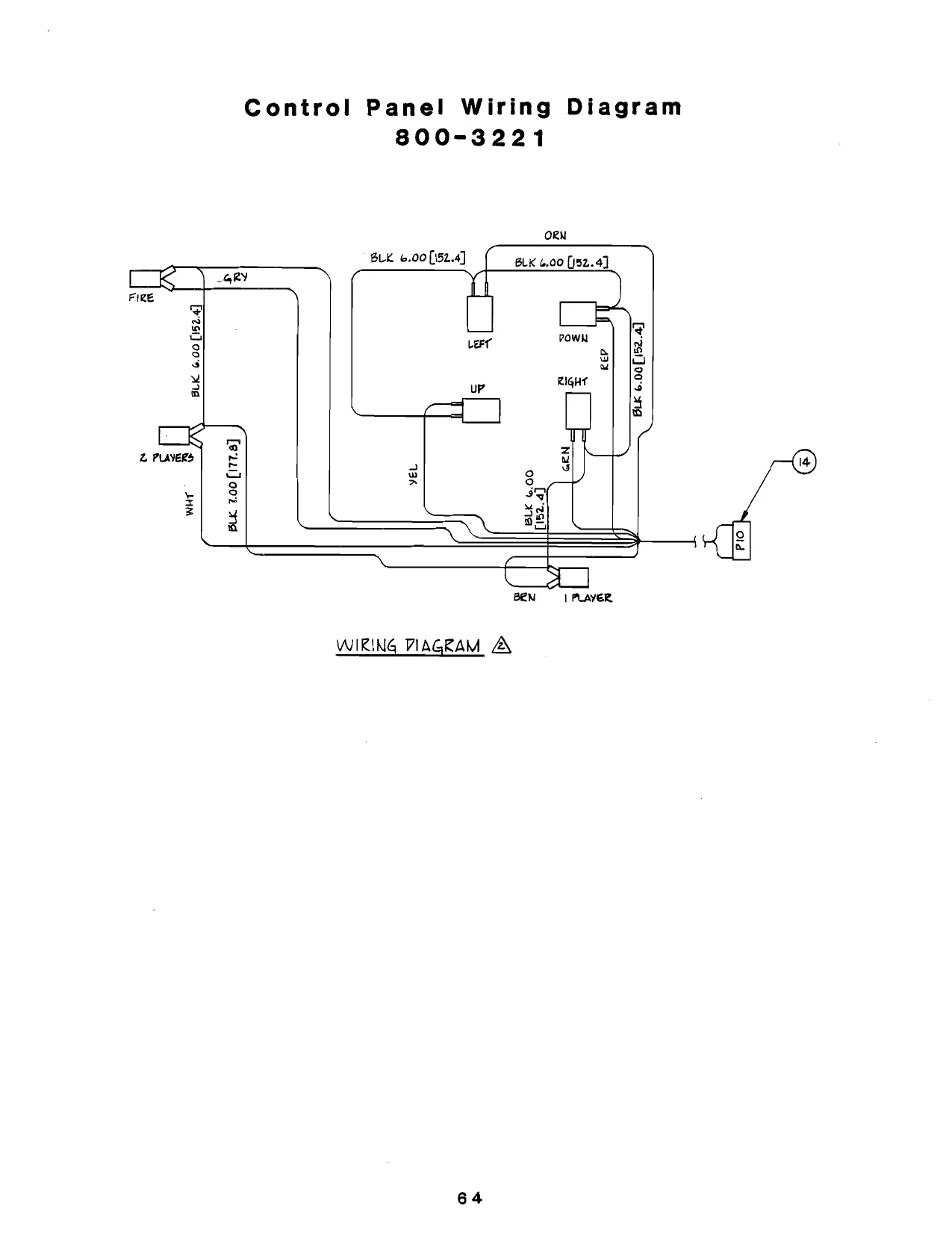
ASSY CONTROL PANEL "005"
ITEM
a1 QTY. REQ'D
Oo DW ww FF F FF FSF A
mw = PART_NO.
510-0059
282-0005-12
283-0025-00
284-0036
284-0016-00
280-0329
240-0009
253-0031
510-0023
253-0252
280-0005
280-0327
250-0517
800-3217 DRAWING NUMBER 800-3221
DESCRIPTION
Joystick 4 way long shaft
Bolt Carriage #10-24 X .75L
Nut, Hex Mach #10-24
Washer, Split Lock Steel #10
Washer, Flat SM OP #10
Nut, Hex Pal 1/2-13
Button Plunger, Yellow
Spacer, Switch
Assy, Switch
Graphic Control Panel
Cable Tie
Base Tie Wrap
Subpanel Metal Weldment 005
Assy, Harness Control Panel
P/o \feM | P/O féM |
Control Panel Assembly
800-3221
ASSY MONITOR COLOR 19" VERTICAL DRAWING NUMBER 800-0328
| ITEM | QTY. REQ'D | PART NO. | DESCRIPTION |
| 1 | 1 | 200-0022 | Color Monitor 19" Vertical |
| 2 | 2 | 280-0359 | Elec. Crimp Sleeve |
| 3 | 1 | 800-0159 | Assy. Monitor Power Harness |
| 5 | 6 | 282-0017-24 Hex Head Bolt 1/4-20 X 1.500LG | |
| 6 | 12 | 284-0027-16 Flat Washer, Large 0.D. Steel 1/4 | |
| 7 | 6 | 283-0007-00 Nut-Hex, Self-Locking, Mach 10-24 |
Vertical 19” Color Monitor Assembly
800-0328
ASSY GAME ELECTRONICS 005
QTY. REQ'D PART _NO.
800~0216
800-3219
834-0130
800-3220
800-0302
800-0281
800-0332
800-0296
420-0695 DRAWING NUMBER 800-3213
Assy.
Assy.
Assy.
Assy.
Assy.
Assy.
Assy.
Assy.
Decal DESCRIPTION
Video 1 Board Mod
CPU 005
Sound PCB 005
2716 Prom Board
Jumper Plug
Harn Master Intf
Harn, Video Inter.
G80 CG Uni #2
Game Electronics 005
Game Electronics Assembly
800-3213
| (iis Ht
ASSY CPU BOARD
ITEM NO
all
M13
Mis
Wi7
M28 PART NO 150-0088
151-0005 151-0012
151-0020 151-0060 151-0061 170-0194 211-0008
212-0098
230-0013 314-0001 314-0015 314-0018 314-0019 314-0055 314-0058 314-0062 314-0066 314-0067 314-0068 _ 314-0078 314-0083 314-0085 314-0087 314-0093 314-0099 314-0105 315-0041 315-0046
315-0070 316-4346 316-0746
390-0003 471-0101 471-0102 QTY PER ASSY
i
I
wn a—
a a ee UO OS DRAWING NUMBER 800-0107
DESCRIPTION
CAP E l0uf 25V CAP CER 680pf 50V CAP CER .luf 50V
CAP CER 33pf SOV CAP CER .luf 16V AX
CAP CER 220pf I6v AX PC BOARD
CONN PIN TEST PT
CONN M 10 PIN RTA XTAL 8.000 MHZ
1C NE555 1c 7404 Ic 74LS00 IC 74LS04 Ic 74Ls244 Ic 74LS08 IC 74LS74 1c 74LS27 Ic 74.30 Ic 74.832 Ic 74LS02 Ic 74.8240 Ic 74LS14 Ic 74L$139 Ic 74.8374 IC 74LS245 IC 74L$253 Ic Z80 A
Ic 2114
iC 31570-
Ic 1346 IC PROM 32 x 8
LED RED RES 100 OHM 1/2W 5%
RES 1K OHM 1/2W 5%
ASSY CPU BOARD CON'T
4o
4)
A
4g 471-0103 471-0104 471-0122 471-0220 471-0221 471-0331 477-0002 481-0001
481-0006
482-0006 482-0010
482-0014
510-0052
510-0053
213-0001
213-0002 213-0004
213-0005 510-0049 471-0472
280-0330 471-0473
151-0031 en eC OC OCU OC OC RES 10K OHM 1/2W 5%
RES 100K OHM 1/2W 5% RES 1.2K OHM 1/2W 5%
RES 22 OHM 1/2W 5%
RES 220 OHM 1/2W 5%
RES 330 OHM 1/2W 5%
RES PACK 15 X 2.2K DIODE IN4002 DIODE 1N914/1N41 48 XSTR 2N4403
XSTR PE 8050 XSTR 2N4401
SWITCH PIANO DIP
SW PUSH BUTTON SIDE PCM
SKT 24 PIN DUAL INLN
SKT 18 PIN DUAL INLN
SKT 16 PIN DUAL INLN
SKT 40 PIN DUAL INLN
SWITCH 8 POS DIP
RES 4.7K OHM 1/2W 5%
CARD EJECTOR RES 47K OHM 1/2W 5% CAP CER .22UF 16V
CPU Board Assembly
800-0107
0 G0 © os ae
H* O00 eo un =e “1 Uf hI ats Ut of fee
= LJ L| — \ boi oie
it
I secondo nN HEGD eee aN
\e anes U@ «nes @ «nea —G@) ss
ASSY G-80 2716 PROM BOARD
(TEM NO
a! H2 PART NO
151-0058
151-0060
170-0211
213-0001 314-0055 314-0058 314-0059 314-0104 314-0120 211-0008
150-0088 280-0330 QTY PER ASSY
] DRAWING NUMBER: 800-0151
DESCRIPTION
CAP CER .Oluf 16V AX
CAP CER .luf 16V AX
PC BOARD
SKT 24 PIN DUAL INLN
IC 74LS2u4 Ic 74-08 Ic 74LS10 Ic 74LS138 Ic 74LS154
CONN PIN TEST PT
CAP £ l0uf 25V CARD EJECTOR
2716 Prom Board Assembly 800-0151
4 Py = id pL] Lh ee ee 4 14 oa d A 4 |
i = fi a va Loud @
ASSY SOUND BOARD 005
ITEM_NO. QTY. REQ'D PART NO.
314-0125
314-0068
314-0067
314-0051
314-0085
314-0019
213-0003
470-0223
470-0153
470-0123
470-0103
470-0472
470-0392
470-0332
470-0222
470-0152
470-0102
470-0821
470-0471
470-0221
470-0121
470-0101 DRAWING NUMBER 834-0130
DESCRIPTION
IC 741538, U6
IC 74L$32, U17
IC 74LS30, U10
IC 7417, U19
IC 74LS14, U4
IC 74LS04, U1]
SKT 14 Pin Dual InIn, XU26
Res 22K Ohm *4W 5%, R71, R115, R116
Res 15K Ohm %W 5%, RS, R50, R53, R54, R58, R65, R75, R85, R113
Res 12K Ohm ‘dW 5%, R104, R105
Res 10K Ohm %W 5%, R44, R45, R56, R62, R70 R74, R78, R80, R91, R93, R97, R100 - R103, R107, R111, R112, R118, R135
Res 4.7K Ohm %W 5%, R1 - R4, RO, R13, R26 - R33, R41, R57, R106, R141
Res 3.9K Ohm %W 5%, R49
Res 3.3K Ohm %W 5%, R89, R119, R122
Res 2.2K Ohm %W 5%, R42, R43, R68, R69, R83, R84
Res 1.5K Ohm %W 5%, R88
Res 1K Ohm %W 5%, R17, R21, R24, R64, R99, R113, R123, R124
Res 820 Ohm %W 5%, R96
Res 470 Ohm %4W 5%, R12, R16, R20
Res 220 Ohm %W 5%, R95, R134
Res 120 Ohm XW 5%, R94
Res 100 Ohm %W 5%, R61, R82, R87
ASSY SOUND BOARD 005
ITEM_NO. QTY. REQ'D
1 2
2 4
a3 - 8
4 23
5 2
6 1
7 1
8 1
9 1
10 9
gail 6
12 1
13 1
14 1
12 BE 6
16 1
17 4
18 1
19 4
20 1
21 1
22 2
23 3 PART_NO.
150-0023
150-0007
150-0014
150-0009
280-0330
212-0081
212-0115
213-0001
213-0004
481-0031
482-0043
316-1286
316-1302
315-0080
313-0034
315-0035
313-0084
315-0033
314-0001
314-0075
314-0250
314-0097
314-0016 DRAWING NUMBER 834-0130
DESCRIPTION
Cap E 10 MF 16V U-Type, C105, C119
Cap E 4.7 MV 16V U-Type, C50, C51, C66, C106
Cap E 2.2 MV 25V U-Type, C8, C39, C72, C73, C79, C83, C93, C104
Cap E IMF 50V U-Type, C36, C57, C77, C78, C81, C84, C85, C87, C88, C96- C103, C108, C110, C172, C113, C115, C117
Card Ejector
Conn M 4 Pin RTG
Conn M 50 Pin
“Socket 24 Pin Dual InIn, X US
Socket 16 Pin Dual Inln, X 08
Diode MA 150 DI - D9
XSTR 25C - 458C, Q1 - Q6
IC 2716 EPR - 1286,U16
Ic 6331 PR - 5001, U8
IC 8255, US
IC LM324, U12, U18, U23, U25, U26
IC MM5837, U13
IC MB 4391 M U28, U30, U31, U32
IC CD 4016, U29
IC NE 555 DIP, U3, U21, U22, U27
TC 7415393, U9
Tc 74LS293, U14
TC 74LS161, U7, U15
IC 74123, U1, U2, U20
ASSY SOUND BOARD 005
ITEM _NO. QTY. REQ'D
47 4
48 2
49 1
50 1
51 7
52 1
53 1
54 1
55 2
56 2
57 3
58 7
59 2
60 1
62 31
63 7
65 6
66 1 PART NO.
153-0066
153-0065
153-0003
153-0041
153-0002
153-0038
153-0034
152-0031
152-0038
152-0072
152-0032
152-0033
152-0005
152-0054
151-0041
151-0005
150-0037
153-0031 DRAWING NUMBER 834-0130
DESCRIPTION
Cap Tant 10 MF 16V, C13, C43, C46, C63
Cap Tant 3.3 MF 16V, C14, C15
Cap Tant 2.2 MF 25V, C95
Cap Tant 1.5 MF 25V, C120
Cap Tant 1 MF 25V, C17, C25 - C27, C44, C61, C62
Cap Tant .68 MF 16V, C75
Cap Tant .47 MF 16V, C28
Cap Film .1 MF 50V, C35
Cap Film .047 MF 35/50V, C9, C59
Cap Film .039 MF 50V, C47, C48
Cap Film .022 MF 50/100V, C55, C56, cor
Cap Film .01 MF 50V, C11, C34, C42, C67, C68, C70, C71
Cap Film .0047 MF 50V, €52, C53
Cap Film .001 MF 50V, C33
Cap Cer .1 MF 25V, C7, C10, C12, C15, €18-C24, (29-C32, C37, C38, C40, C44, C45, C49, C54, C58, C60, C63, C69, C73, C76, C82, C111, C118
Cap Cer 680 PF S50V, C80, C89, C90, C107, Ci09, C114, C116
Cap E 470 MF 16V T-Type, Cl - C6
Cap Tant 3.3 MF 25V, C41
ASSY SOUND BOARD 005
ITEM NO.
m7s
m79 QTY. REQ'D PART _NO.
470-0334
470-0272
220-0196
220-0197
470-0105
470-0684
470-0474
470-0394
470-0224
470-0154
470-0104
470-0513
470-0473
470-0333
470-0273 Res
Res
Vol
Vol
Res
Res
Res R22,
Res
Res
Res
Res R63, DRAWING NUMBER 834-0130
DESCRIPTION
330 K Ohm %W 5%, R35
2.7 K Ohm %W 5%, R48
Cont 50 K Ohm, VR1 - VR8
Cont 500 Ohm, VR9
1M Ohm %W 5%, R14, R15, R36
680 K Ohm %W 5%, R39, R81, R90
470 K Ohm %W 5%, RIO, R11, R18, R19. R23
390 K Ohm %W 5%, R67
220 K Ohm %W 5%, R66
150 K Ohm 4W 5%, R46, R51, RIB
100 K Ohm %W 5%, R40, R52, R55, R59, R76, R77, R79, R92, R110, R120, R121, R136, R137
Res R73,
Res R117
Res
Res 51 K Ohm %W 5%, R47, R50, R60, R72, R108, R109, R125 ~ R132
47 K Ohm %W 5%, R6 ~ R8, R86,
33 K Ohm &W 5%, R138, R139
27 K Ohm %W 5%, R34
ASSEMBLY VIDEO 1 BOARD MODIFIED DRAWING NUMBER 800-0216
ITEM_NO. QTY. REQ'D PART_NO. DESCRIPTION
1 1 800-0212 Vic Replacement Board Assembly
2 1 800-0106 Video 1 Board Assembly
Video | Board Modified Assembly 800-0216
ASSEMBLY VIDEO 1 BOARD
ITEM NO. QTY. REQ'D
1 3
2 1
4 2
5 7
6 61
7 u
8 2
9 1
10 3
W 1
12 1
13 2
14 2
15 1
16 2
7 1
18 1
19 1
20 1
21 4
22 3
23 2 PART NO. 150-0088
151-0005
151-0008
151-0011
151-0058
151-0060
151-0061
152-0007
170-0193
211-0008
230-0009
212-0099
314-0001
314-0040
314-0046
314-0058
314-0059
314-0062
314-0067
314-0068
314-0070
314-0073
314-0076 DRAWING NUMBER 800-0106
DESCRIPTION
Cap E 10uf 25V, C80-C82
Cap Cer 680pf 50V, C79
Cap Cer .00luf 50V, C65
Cap Cer .Oluf 50V, C54, C64
Cap Cer .Oluf 16V AX, C57, 60, 63, 70, 71, 84, 86,
Cap Cer .luf 16V AX, C13-53, 56, 58, 59, 62, 66-69, 72-78, 83, 85, 87, 88, 89
Cap Cer 220pf, 16V AX, C1-C9, cil, cl2
Cap Film .001, 250V, C55, C61
PC Board
Conn Pin Test PT, TP1-TP3
Xtal 15.46848, Y1
Conn 15 Pin M RTA
IC NE555, UT U10
IC 74L8125, U32, U50
IC 74LS04, U60
IC 74LS08, U5, U44
IC 74LS10, U41
IC 74LS74, U6
IC 74LS30, U59
IC 74LS32, U48
IC 74LS86, U3, U4, U39, U40
IC 74LS175, U49, U54, U55
IC 74LS157, U56, U57
ASSEMBLY VIDEO 1 BOARD
ITEM_NO. QTY. REQ'D
yn YN OT = s+ YB LH
=
my © MY NY WwW
am PART_NO.
314-0077
314-0085
314-0139
314-0087
315-0039
315-0042
315-0065
314-0093
314-0138
314-0104
314-0123
314-0124
314-0125
316-0806
471-0102
471-0103
471-0122
471-0202
471-0222
471-0242
471-0330
471-0331
471-0472
471-0563
481-0006 DRAWING NUMBER 800-0106
DESCRIPTION
IC 74LS166, U33-U36
Ic 741814, U37, U47
IC 748163, U53
IC 74L$139,U15
IC 4015, U16-U31
IC Custom Chip U58
IC 93419, u9
IC 74LS374, UIT
IC 745283, U38
IC 74LS138, U51
IC 74L$257, U13, U4
IC 74L$33, U7, U8
IC 74LS38, U46
IC 32X8 Prom, U52 Res 1K Ohm :M 5%, R4-R6, RIS, RIG
Res 10K Ohm %W 5% R7, R17
Res 1.2K Ohm 4W 5%, R10, R13
Res 2K Ohm W 5%, R14
Res 2.2K Ohm %W 5%, R21-R23
Res 2.4K Ohm 4W 5%, RO, R12
Res 33 Ohm 4W 5%, R19, R20
Res 330 Ohm %W 5% R24 - R31
Res 4.7K Ohm 4W 5% R8, RII
Res 56K Ohm %W 5%, RIS
Diode IN914/IN4148 DI-D11-9
ASSEMBLY VIDEO 1 BOARD
ITEM NO. QTY. REQ'D PART NO.
482-0006
482-0014
213-0004
213-0005
213-0012
315-0067
477-0002
471-0221
280-0330
213-0003
314-0140
314-0053 DRAWING NUMBER 800-0106
DESCRIPTION
XSTR 2N4403, Q2
XSTR 2N4401, Q1
SKT 16 Pin Dual INLN, UU16 - XU31, XU38, XU42, XU43, XU5S2, XU53
SKT 40 Pin Dual INLN, XU58
SKT 28 Pin Dual INLN XU9, XU12
Header 28 Pin U12
Res Pack 15 X 2.2K, RP1
Res 220 Ohm 4W 5% R1 - R3
Card Ejector
SKT 14 Pin Dual INLN XU45
IC 74874, U45 Ie 748175, U42, U43
Video I Board Assembly
-0106
TO aE wiReD NTH IRE (SOLDER AWG 22 BIS Wi CROSS HEAOER FINS 10 PLC)
ASSY VIC REPLACEMENT BOARD
{TEM NUMBER
© On nu FwWwn
FwWwN =O PART NUMBER QTY PER ASSY
150-0088 151-0060 1
170-0227A 213-0014 314-0058 314-0059 314-0062 314-0067 314-0070 314-0136 314-0072 314-0075 314-0085 280-0354 we nye ne ewe =e Be HW oH DRAWING NUMBER: 800-0212
DESCRIPTION
CAP E 10UF 25V CAP CER .1UF 16V AX
PC. BOARD
SKT 40 PIN WIRE WRAP
Ic 74LS08 1c 74LS10 Ic 74.874 1C 74L$30 IC 74LS86 IC 745151 IC 74LS174 IC 74LS393 Ic 74LS14
PCB SUPPORT LOCKING
This page carries no recoverable text. It is a drawing or a photograph. See the original scan.
ASSEMBLY G-80 POWER SUPPLY CHASSIS
ITEM _NO. QTY. REQ'D
1 1
2 1
3 1
4 1
5 6
6 8
8 1
9 1
W10 1
m1 1
m2 1
m3 1
16 1
7 1
18 1
19 6
20 6
21 5
22 6
23 6 PART NO. 530-0016
250-0460
250-0461
800-0170
253-0206
281 -0032-06
482-0104
313-0023
313-0014
313-0015
482-0100
482-0019
420-0557
280-0117
420-0575
281-0001-08
280-0341-00
310-0006-01
284-0001-00
284-0031-00 DRAWING NUMBER 800-0191
DESCRIPTION
Heat Sink G-80 Power Supply
Chassis Support G-80 Power Supply
Cover G-80 Power Supply ~
PCB Assy G-80 Power Supply
Support PCB Threaded
SCR PN HD Phil Thrd Fring 6-32 X .375 LG
Power Transister TIP 141
Neg. 5 Volt Regulator 320T5
Pos 12 Volt Regulator 340712
Neg 12 Volt Regulator 320712
Power Transistor (Audio AMP) TIP 125
Power Transistor (Audio AMP) TIP 120
Decal, Fuse
TAB Rivet, Male 1/4"
Decal Power Supply B
SCR PN HD Phil #4-40 X .500LG
Washer Shoulder #4
INSL XSTR To-220
Washer Flat #4
Washer Lock Split #4
ASSEMBLY G-80 POWER SUPPLY CHASSIS DRAWING NUMBER 800-0191
ITEM_NO. QTY. REQ'D PART_NO. DESCRIPTION
| 24 | 6 | 283-0021-00 Nut Hex Mach #4-40 | |
| 25 | 1 | * 800-0243 | Assy. Harn XSTR G-80 P1 |
| 26 | 1 | 800-0244" | Assy. Harn XSTR G-80 P2 |
| 27 | 1 | 800-0245 | Assy. Harn XSTR G-80 P3 |
| 28 | 1 | 800-0246 | Assy. Harn XSTR G-80 P4 |
| 29 | 1 | 800-0247 | Assy. Harn XSTR G-80 P5 |
| 30 | 1 | 800-0248 | Assy. Harn XSTR G-80 P6 |
| 31 | 1 | 310-0007-01 Ins1 XSTR "H" (To-218) |
G-80 Power Supply Chassis Assembly
800-0191
SACK SIDE OF HEAT SINK ITEM I
cucuy sok On oc) ITEM +
G-80 Power Supply Chassis Assembly
800-0191
SEE DETAIL AT
HARN INSTALLATION
Pry DETAIL =
’
irEm at warn (et)
vTEM 20
rTM 19 VIEW “AY TYP.
PC ASSY G-80 POWER SUPPLY
ITEM NUMBER
Nn=—- OCW ON aw FwWhN =
NNN NN NKR HY FS He Se mes NOU FWNH HSH ONAU EG
a2
m2 B30 B31
B33 PART NUMBER
150-0088
150-0092 150-0095 150-0096
150-0097 151-0002
151-0007 151-0011
151-0012 151-0021
170-0222
212-0020
212-0081
313-0001 471-0011 471-0101 471-0102 471-0103 471-0104 471-0222 471-0223 471-0332 471-0182 471-0681 473-05R0 473-O0R2 475-0004 431-0002
481-0004 481-0006 482-0006 482-0014 514-0002 514-0003 514-0006 514-0008 QTY_PER_ASSY
—- = ONNNWON A=NKN = B= = = HH A= NHwW Be HK HHH KH BW FH KH Pw DRAWING NUMBER: 800-0170
DESCRIPTION
CAP E 10UF 25V
CAP E 100UF 25V
CAP — 3300UF 25V CAP E 6800UF 16V
CAP E 4700UF 25V CAP CER 100PF 50V
CAP CER .OOSUF 100V CAP CER .O1UF 50V
CAP CER .1UF 50V
CAP CER 20PF 50V
PC BOARD
CONN M 10 PIN RTA
CONN M 4 PIN RTA
\C LM723 DIP RES 10 OHM 1/2W 5%
RES 100 OHM 1/2W 5%
RES 1K OHM 1/2W 5% RES 10K OHM 1/2W 5%
RES 100K OHM 1/2W 5%
RES 2.2 OHM 1/2W 5%
RES 22K OHM 1/2W 5% RES 3.3K OHM 1/2W 5% RES 1.8K OHM 1/2W 5% RES 680 OHM 1/2W 5%
RES .05 OHM 5W 3% RES .2 OHM 3W 5%
POT 1K CAR PCMTV
DIODE MR751
DIODE MR5O1 DIODE 1N914/1N41 43 XSTR 2N4403 XSTR 2N4401
FUSE 3 A NORM
CLIP FUSE MTG
FUSE 1.5 A NORM
FUSE 10 A SLO
PC ASSY G-30 POWER SUPPLY con't DRAWING NUMBER: 800-0170
| 37 | 800-0191 | 1 | SCHEMATIC REF |
| 36 | 471-0220 | ] | RES 22 OHM 1/2W 5% |
| 39 | 471-0221 | 1 | RES 220 OHM 1/2W 5% |
G-80 Power Supply PC Assembly
800-0170
Cle’ eH L IC = be
i aaa e I (eee :
This page is a drawing, shown as the original scan.
This page reads as a drawing: its text was drawn rather than typeset, and comes out in fragments. See the original scan.
This page reads as a drawing: its text was drawn rather than typeset, and comes out in fragments. See the original scan.
This page reads as a drawing: its text was drawn rather than typeset, and comes out in fragments. See the original scan.
7 6 5 4 | 3 | 2 | 1 REVISIONS | oa oF = 7 ; <j Tone [Ue DESORIFTON DATE | aPeaqyeD 20-2 40-47 50-87 60-67 77 100-10) TO-"7 120-127 CSE SHT 3 FOR CHANGES [ur-8t {20 Jeo jzo ke 20 je [eo jo [zo Q 6 8 4 SF Sy 3 Ar 2 +5V 7 7 v 7 7 1 ANS Al4 6 6 6 6 G G 2 6 O45 — 5 5] 5 Ls 5 5 we G1 G2 @Pygm £00" 207 4 | 4 41 4 4 19 gig 7 ui-v2s 1 Pay 20-217 D ur 3 ue U4 EI us us 3 ur i Us 3 ug 3 ulo 2 12 220-227 2716 2 2116 2] 276 2716 2] e7i6 2] e716 2] ene 2] 276 f I Py 250° 257 u i ' i i 4 12. 4 240-247 = 10 Ey 2 [23 a3] a 23 sb 250-257
- 22) 22| 22! 22! 22 ec U30 6 pr 260-267 1 1 ! rae naan SpoyspspSpey 7 [POP GT TEE PEE” 2 FoLnpsy aps ysl eet ae 7 270-27 L a roy + nt -—te ie it tC + + 4 + ives + + an 4741508 7 th . + wet nO r 1 tt tC ] a as Cc . > ALS 741808 130-137 140-147 150-157 160-167 200-207 210-217 220-227 30-237 240;247, he Tio ai a® je ? deo Jeo _beo 420 deo 2 deo bec deo rt }. 3 8 8 Ly Es 8 £ 8 pL 7 7 7| 7 7 7 7 7 7 7| c HHH L {7 12741808 6 [6 6 6 6 é é 6 é 6 13} 27} $ 5. 5 5 5 5 5 5 5 5 Al 4 4 4 4 4 4 4 + 4 + 9741508 3 vil 3 uz 3 urs 3] ua 3 uls 3 ule 3 wT 3 rr) 3 vig 3 u20 10] u27, & 1 2) 2716 2 2716 2 2716 é e7i6 2 2716 2 2716 2 e716 2 2716 2 one 2 2716 — AS — 1 I t 1 t 1 1 i t 23 23 23 23 23 23 23 2 2; 22 i [22] [22] 44 22 22 22 22 22 iis)ialisfiei7 Sfiofi spss] BQOE Topifispalisfieli 7 9] ispeli7 pop pstepspey7 a popifisphishiefi7 00g? | pest 140-47 Trt oa a y 150-157 ct — + AIA AIS IZ ALT o ts08 I res B rofu2d aq 7 3 [aholfis} oy . : 7 z 7 3G a3) é 6 6 LY 5. 5 5 = a2€>——S a2 4 + = ves BUFFER w 3] vai 3 vee 3 ues T4Ls244 9 u 2] 2716 2] e716 2] e716 Q aga) i i 9 23 23 hn 22 fez PD UKM X12, 19 # ® Teo Teo Yeo DS 01 D2 D3 D4 D5 Ds D7 12741808 250-257 260-267
Tor | cove PART OR NOMENCLATURE [RtQD | IDENT IDENTIFYING NO. OR DESCRIPTION creacnen cacace ck, GEE | C10,¢12,c13, | Co.ciyci4cié, BiERsons we NeHes | [NT NO Gremlin Industries, Inc. 5 cisci7cia, | ci8ceices, HrOUERANCES ARE: nen isoa, enifernin Se Can c2e C24, C25,C27. FRACTIONS DECIMALS ANGLES: Su23 pS SUFFER C2626, ’ : ae Ca A a Situs | .o1s a PR falas | 2716 PROM ol = : Board [SHE] EOE GENT HO TORARING FG TREV a D BO00-0151=< APPLICATION DO NOT SCALE _DRAWING [SHEET 4 OF 4
This page reads as a drawing: its text was drawn rather than typeset, and comes out in fragments. See the original scan.
| 6 | 5 | t | 4 | | | 3 | 2 | | | 1 |
ay REVISIONS
| we UND (SH 7) | ev ee | zone [oR | DESCRIPTION | GATE | APPROVED |
| ua TRIG | we as3i | MB 4391 | SEE SH #1 | D |
NOISE | NOISE 2
| RSG | taza 666 TRH | R109 ka7 | 448 yeuicorrer soup 2! | sv | sv | |
| 10K | 4.7] io0K | chk iH | We | 100K | ||
| us | wy BR oF | \ | 5 | ye Shy ourltl +) - | WHISTLE SOUND | |
| MM 5837 | = | 25V | 5OV | u26 | u26 | Rul |
| 4 | fo | R22 Rug | jz. b M324 | LM 324 | hs | ik | |
| 2V <—— > | 10 | ZV <— | +N | ee Oe ee | D | |
| cag | 3.3K 33k Bl ¢ 3), 7 cons | RIB | ||||
| 80 P | Riza | a | ISK | |||
| Z | SOV | IK | 3 | lav | ||
| Rizo | our TH | C9 022m gy | ||||
| = | = | m™ |
SOV R103 RIS 22K 10K
| Rilo | 73 | a3 |
| 22K | | 2.2m | 2.2K] |
+ + <5) 2sv vy LM 324 nioz L 1K wv 1
sv SY R52 RSI
| R3 | Wok ISDK | u3r | waisTLe c |
4.7K
| LARGE | a | t | imsza | I giag | | M8439 cas | TRIG | |
| Mosy SIKH ISK SK I | ol, +—4 | w our} it — EXPLOSION SND | ||||
| (su7 ) | te 7 | yt | - | Lesz | x0 | Sov |
| Ce | er | cm} a7 | ||||
| NOISE | | it | re I | SOV | 1) cua | Rug, | |
| im GOK gy 4 3, | 80 P | 10K | ||||
| Sov | ule | SOV |
= ov U3! cu7
| ote sae | MB4391 | Im | SMALL |
F 33K sh
| sv | +74 | w our| 4 | = EXPLOSION |
‘SND
| Ro | ' | 50V | 7 cue” | rt |
4.7K
| sy sy si? | sv | RIB | “aor | |
| 3 | 1 | Rize Rizs RBI Riza R127 Riaz R130 Ri28 | ||
| ' | zh ytd | i | SIK SIK SIK SIK SIK SIK Stk SIK | B |
+ tz
| SMALL | aK (M324 | wae | +ca7 | + C36 [ow + C100 +98 + clo3. | Clot «f+ C99 | < |
| EXPLOSION | ; | G 7 | a IM | im ie ie |
| snp TRIG 5 4 | Sov Sov Sov Sov Sov Sov 50V Sov | } | ||
| (sH7 ) | wah | 2 eae | ii | 3 |
cno 3
| Rec | COS RB7 we | 7 | 1M. | vesiué aye 3 | rape ay a ytr ay | 7 |
| NOISE 2 | SR LC UE Te My ure | ~ sono [vee J [v | VR7 ca VRS ‘sal VR3 vee 1 [vee 1 [vera 1 | x | |
| (sH9) sy sy | cog | 16¥ | 25v to | s0v | 0 |
+O1M R36 *)
| ay | ok | ee | LARGE SMALL BOMB Dror PISTOL MISSILE HELICOPTER WHISTLE MELOBY |
| Pa | EH | EXPLOSION EXPLOSION SOUND SHOOT SOUND SOUND «SOUND (sH7) |
4.7K ‘SOUND SOUND (SH9) fern) SND TRIG 5 J 9 PARTS LIST (su7 ) Toatess OTNERATSE SRECIED SIME ae 1H INCH “CECIMALS Faacrons anaes, aeRO AE PRAWN SON DUONG [12-17-81 [FS cree 2260) Sound Board race [GOGE TENT NO TORAWING NO.
NEXT ASSY ‘USED ON 8834-01304 T REV
[APPLICATION ‘DO NOT SCALE DRAWING
PISTOL ‘SHOOT TRIG. (sH7) a!
= PISTOL SHOOT SND (sus )
4700P + roe 35V/S0V LF
0B MA 150
{_———» BOMB DROP SOUND ; 2 | 1 mae eer one SEE SH #1 0
vy ——+—___{) é f}
© sv tg, see? iev (8) © <2) oO) ¢ =®
470m 02 ov [{——) + é —® & 03 | —— (ay -—® 04
De 2) (3) © () 07 a) 3) ‘ i
834-0130 [A| @ RESET |——(33) LK} as =<) () Al (37) ) va (39) AB [© 5 Aa as {+ ——@ cI} he —, <2) AT (48) {50)
TART On NOMENCLATURE TEM 1DENARTING NO. On DESERITON if
TNLESS OTHERWEE SPECIFIED DIMENSIONS ARE IN INCHES HTOLERANCES ARE: anaes [SORTRACT NO. PARTS LST
Rao ORAYN'SON DUONG |I2-18-Bi| PROS oie |2265} Sound Board MEG Gt ‘SE | CODE TENT NOT ORAWING NO. T REV ad PROECT dD) ~—« 8 34-01304 DO_NOT SCALE DRAWING
This page reads as a drawing: its text was drawn rather than typeset, and comes out in fragments. See the original scan.
| 5 | 4 | | |
REVISIONS DESCRIPTION DATE, CTC [10-28-30] G | SEE SH I
| FOR REVISIONS | SD | |s7e |
aaY vaxtex AE ae
PHT 220 Le
u Sfez5 v2| Slo) vs 4.
| va | PR | oo |
bs
GREEN (sH6) (she)
| (07 DaDE D4 D3 bE DI OB) | ii aa | C7 ca | BRE AL AG CS C4 VE) |
5s ta [ia [s |e fo fs 2 |s jv ls |s [6 fro [vs
| 8 | a | B | ||
| Lsi57:US7 | iz | ig] | LSIS7 | —-US6 |
¥
| - | Tas 2 | 72 | rn | a | ||||
| fi | is [ee a: | A | is | fa | i | 27 | |26e | les |
| mn | awe | as | aa | es | as | Azar | Ao [24 | |
| pe} | s | 23 | ||||||
| 7 | 6 | 22 | ||||||
| 2 | z | 93419 | U9 | i | ||||
| a | (28 PIN) | = |
2 19 10 18 mn 17
ob. tees]
L_ 2ST (sH6) i
| + | oF | A BLUE |
U53— iop®
| TT tool | ses | pts |
=
Fa : zl if id ie [in ey rs +
| if | 19044) | TS 10 |
| Te08
fie fis [ia
32*%8 PROM #3 - Al AZ A3 AS 15.
ep i qi
MYWT (SH 6) ia fiz [sia ae vee 's175 L piss ryapoyn 7Yeys C56, C58, C59, a
19}
| 12) | >ot | EXT BLK |
| el | 04 | cle |
C624 Ces-Cedy €72-¢78,¢93,c85] €86,CB8,CB>
C71, C84,C87
| i | i | — | |
| isya]OyH |7Ye | [2ys | + | {3} Skt |
[gRC_SRL RL WG RWT WAS VRAS (sn e) ir DESCRIPTION
BIMENSiGne Ane IN WeRES Gremlin Industries, Inc. DECIMALS ANGLES San Bioge, Catiternés 92123 Prey. caTTece | Video Board
OBE TENT NG TORAWING WO
| SEE_NOTE ON SHEET G. | or Aa | BOO | 0106 |
| Cc | APPLICATION | seer] OF 7 |
4 1 RED
COMPSYNC.
COMP VID
COMPEYNC
800-0106
This page reads as a drawing: its text was drawn rather than typeset, and comes out in fragments. See the original scan.
This page reads as a drawing: its text was drawn rather than typeset, and comes out in fragments. See the original scan.