Blaster Service Manual (16-3021-101)
Blaster (Williams / Vid Kidz, 1983) · Manual · 51 pages · 52 sections · original scan
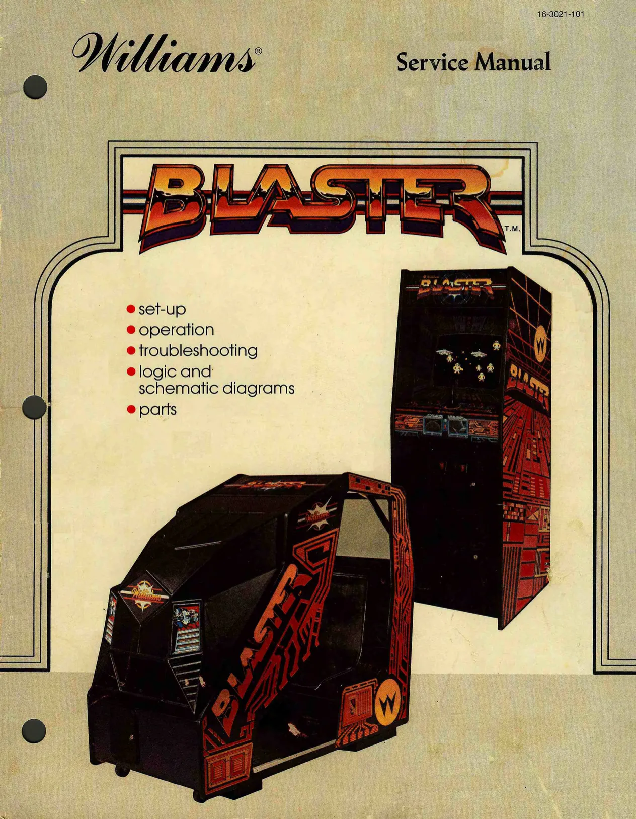
This page is a drawing, shown as the original scan.
CONTENTS
@ CHAPTER1 Game Setup............... oe .3 Warnings & Notices... cen ere teen e ene e ee 5 Game Features «vice. eat eee eee ete ene eee teens 5 Examine Your Game... 2.0.6.6 e eens 6 Location of Controls... 0.0. ect netet ene eee 6 Optional Extension Monitor Connections. ......... 6.066 c eee ee 7
©@ CHAPTER 2 Game Operation ...........2ce tener e cece tren eeeeeneene 9 Power Turn-On. .... Game Operation Bookkeeping Totals... 0.0... eee ee tent e ete eee 40 Game Adjustments. .... 0.06.0 een eee eens "4 Definitions of Pricing Terms... 2... cee eect nes 43
@ CHAPTER 3 Troubleshooting Procedures ..........0ceeseeee eee ee eens 15 INfrOdUCTION, ree enna 46 PowerUp Tests... eee eb e eee tenet n eee 416 +5VDC Power Supply Adjustments .........00. 000: c ccc eee erence eee 47 Self-Diagnostics 0.6... cette eee tenet teens Diagnostics Mode Tests . . Sound Board Diagnostics CMOS RAM Data Test Protocol... 20-0. eee 22
@ CHAPTER 4 Schematic and Logic Diagrams ...............0.eee eee 23
@ CHAPTER 5 Parts... 0... cece ec cece t eee e tenet e eee eeteeee 45
This page carries no recoverable text. It is a drawing or a photograph. See the original scan.
CHAPTER 1 Game Setup
Warnings and Notices
Game Features Examine Your Game
Location of Controls
Optional Extension Monitor Connections
This page carries no recoverable text. It is a drawing or a photograph. See the original scan.
Warnings & Notices
- FOR SAFETY AND RELIABILITY, WILLIAMS does not recommend or authorize any substitute parts or modifications of WILLIAMS equipment.
- USE OF NON-WILLIAMS PARTS and modifications of game circuitry may adversely affect game play, or may cause injuries.
- SUBSTITUTE PARTS, MODIFICATIONS AND GAME “CONVERSIONS” may void FCC type-acceptance.
- SINCE THIS GAME IS PROTECTED by Federal copyright, trademark and patent laws, so-calied game “conversions” may be illegal under Federal law,
- THIS “CONVERSION” PRINCIPLE ALSO APPLIES to unauthorized facsimiles of WILLIAMS equipment, logos, designs, publications, assemblies and game (or game features not deemed to be in the public domain), whether manufactured with WILLIAMS components or not.
RF INTERFERENCE NOTICE: CABLE HARNESS PLACEMENTS AND GROUND STRAP ROUTING on this game have been designed to keep RF radiation and conduction within levels accepted by FCC regulation.
TO MAINTAIN THESE LEVELS, reposition harnesses and reconnect ground straps to their original placements if they should be disconnected during maintenance.
NOTICE: Assemblies secured to the plastic-upright cabinet use special #8 xX "he screws, WILLIAMS part no. 4608-01081-11. Always replace these screws with the same type. NEVER attempt to substitute ordinary sheet-metal screws.
Game Features
FIRST-PERSON ACTION IN MOST VIDEO GAMES players have to watch a “hero” go through the motions for them, Not so in BLASTER video!
IN BLASTER VIDEO players are right there in the action. When they move the joystick, their whole point-of-view changes just as if would in a jet aircraft or in the space shuttle! When they press THRUST the stars, asteroids and interstellar gas clouds shoot by at death-defying speed.
BUY-IN FEATURE CONTINUED GAMES. After completing a game players are encouraged to continue where they left off. (At factory settings upright BLASTER models even offer continued games at half-price.) Continued games are more challenging than original games. So continued games tend to involve skilled players at the level they prefer and to increase collections.
PLAYERS CHOOSE STARTING DIFFICULTY FOUR WAYS TO START. Players may begin a game in any of the first four waves: (1) Planetoids; (2) Robot Grid; (3) Saucerland and (4) Vampires. This feature allows players to select the amount of challenge the game will offer, while increasing the game's collection for the operator.
49-WAY OPTO JOYSTICK MODELED AFTER A MILITARY AIRCRAFT JOYSTICK, the BLASTER joystick is engineered to fit the hand and provide quick game response as well as durability.
ELECTRONICALLY THE JOYSTICK IS UNIQUE. Six optoisolators (three on the X-axis and three on the Y-axis) are positioned to accept both direction and speed cues. A resolution of 49 directions and speed combinations is possible. See PLAYER CONTROLS below.
STEREO COCKPIT SOUND STEREO SOUND. Since “true” stereo requires two sound sources, BLASTER video has not only two speakers, but two. entire sound boards.
Examine your Game
When you receive a new WILLIAMS game, examine it carefully before you power it up. Be sure it was delivered in good condition! CJ INSPECT THE OUTSIDE of the shipping carton and/or game cabinet for shipping damage.
CJ UPRIGHTS: Unlock and set aside the top-rear panel. Undo the two trunk latches on the inside of the bottom door. Open the door. Now check circuitry,
(J PLASTIC UPRIGHT: Unlock and open the rear door. Now check circultry.
(| COCKPIT GAMES: See Figure 1. (4) Unlock the access door on the front of the game. (2) Now extend your arm to the left and right inside the door. Undo the two hood trunk latches. (3) Raise the hood. (4) Loosen the two access screws at the sides of the circuit board panel. (5) Raise the panel and inspect circuitry.
(| ARE CONNECTORS SECURELY ATTACHED? Reconnect any found loose. DON'T FORCE CONNECTORS. They're keyed and only fit one way.
[J] ARE PLUG-IN CHIPS FIRMLY seated in their sockets?
(1 UNWRAP THE POWER CORD coiled inside the cabinet. UPRIGHT GAMES: place the strain-relief plate in the slots as shown in Figure 2. PLASTIC GAMES: position the cord in the groove of the cabinet floor. COCKPIT GAMES: Strain-relief providedthe power cord is secured under the front edge of the cabinet below the access door; free the power cord Strain-relief not provided extend the power cord through the hole in the cabinet floor. DON’T PLUG IT IN YET! (J SCRUTINIZE MAJOR SUBASSEMBLIES, such as the monitor, control panel, transformer chassis and power supply. Make sure they'’re securely-mounted.
Figure 1. Cockpit model with hood raised.
Location Of Controls
THE ON-OFF SWITCH is located: in the top right corner of the rear of the cabinet (UPRIGHT) on the bottom of cabinet below access door (COCKPIT) in center over rear door (PLASTIC).
THE POWER INTERLOCK SWITCH is located behind the topright corner of rear door UPRIGHT & PLASTIC inside the access door on the front of the game COCKPIT. The interlock switch is a spring-loaded DPDT type that will turn off the game when you open the door. For servicing purposes, pull the switch out and the game will power up.
THE DUAL VOLUME CONTROL is located on the circuit board panel. On uprights and plastic cabinets you can adjust it from the coin door. On cockpits models open the hood to adjust volume.
DIAGNOSTIC SWITCHES are on the inside of the coin door in upright and plastic cabinet games. In cockpit games they're under the hood and on the top-right side as you face the front of the game.
These switches are used to access the Diagnostic-Mode Tests, the BOOKKEEPING TOTALS screen and the GAME ADJUSTMENTS screen. Refer to appropriate sections for information on each of these important features.
MISCELLANEOUS CONTROLS. The memory-protect interlock switch is near the diagnostic switch bracket (see above). This switch must be open when you clear BOOK- KEEPING TOTALS or make GAME ADJUSTMENTS, It automatically opens when the coin door is open on upright and plastic cabinet games and when the hood is up on cockpit games. The CPU board reset switch is located on the CPU board beside the batteries. jhe cashbox aavance switch, found inside the cashbox door on all models, allows bookkeeping information to be audited without permitting it to be zeroed. A sound-board diagnostic switch is diagonally across each sound board from a large, strap-mounted axial capacitor. Sound-board diagnostics are explained in chapter 3.
Figure 2. Power Cord Strain Relief (Upright)
wa so
Figure 3. Cockpit Model Cashbox Security Plate
Optional Extension
Monitor Installation
An extension monitor must be connected to 115VAC power through a 1:1 isolation transformer. The transformer must have a minimum current rating of 1A. Connections from the WILLIAMS video system to the monitor inputs may simply be paralleled to provide the extension monitor with sync and video,
CONTROL PANEL
P/O PLASTIC CABINET
CONTROL, PANEL RELEASE es
UNLOCK LOCK
Figure 4. Access to Plastic Cabinet Control Panel
This page carries no recoverable text. It is a drawing or a photograph. See the original scan.
CHAPTER 2. Game Operation
Power Turn-On
Game Operation Bookkeeping Totals Game Adjustments Definitions of Pricing Terms
Power Turn-On
WHEN THE GAME IS FIRST TURNED ON general illumination should come on and a moment later a scanning “rug pattern” indicating the RAM test should appear on the screen, Next the rug should become stationary as the ROM test Is performed. In a correctly-running game the rug pattern will be followed by the message “INITIAL CHECKS INDICATE OPERANTIONAL”. If RAM or ROM failure messages come up on the screen instead, refer to Power-Up Tests in TROUBLESHOOTING PROCEDURES.
Game Operation
GAME START INSERT COINS; The number of COINS RECEIVED is displayed on the CRI. With four or more coins displayed, pressing 2-PLAYER START initiates a 2-piayer, 3-turn game (adjustable feaiure)
PLAYER CONTROLS CONTROLLED BY THE JOYSTICK, a unique configuration of optoswitches provides a faster response and a greatlyincreased number of vectors in each quadrant for the precise aiming of your spaceship.
TWO SETS OF THREE OPTOSWITCHES each are arranged at right angles to each other. One set is for aiming along the X-axis; the other is for aiming along the Y-axis. With the joystick in tne center position all six optoswitches are biocked.
AS THE JOYSTICK IS MOVED it actuates one cr both sets of switches. The spaceship responds with extraordinary precision due to the sequential action of the optoswitches in each set. Each switch in the set is offset so that joystick action multiplies the circuitry brought in by the switches, increasing the precision aiming of the spaceship.
THE RATE OF X-Y COURSE CHANGE INCREASES as the joystick is moved further from the center position; it decreases as the Joystick is returned toward the center position
SPECIAL CIRCUITRY is inciuded so the spaceship can respond immediately to sudden reversals of joystick movement.
PRESS BLAST! The spaceship fires at planeioids and enemies
PRESS THURST! The spaceship accelerates to maximum speed, GAME PLAY IN A VALIANT SPACESHIP the player defies space and time while vying with robots, vampires, cat fighters and other fearsome foes. The player must BLAST enemies or stay out ot their way to protect his shields (and his turn). A shield may be hit three times before it disintegrates. GAME ACTION IS DIVIDED INTO WAVES. Each wave may have one or several goals, Some of the more-important goals are to...
1 BLAST enemies and planetoids (fleet bonus for eliminating all of one type)
[] pick up spacemen (in time tunnel or space)
C1 dock with energizer E's (restores shields)
(1 BLAST the red saucer first or last (at Saucerland)
G fly through the magic arches (on the Robot Grid)
0 attain wave 30 to enter astral paradise
BAD GUYS @ android @ master mind @ space cowboy @ cat fighter @ planetoids @ space robot @ death rider @ destroyer @ enduro @ star cruiser @ vampire @ X-29 fighter @ red saucer @ runaway ship @ saucer
Bookkeeping Totals
ENTERING BOOKKEEPING MODE. See Figure 5. Inside the coin door (or under the hood on cockpit-model games) is a bracket with three button switches. Set the AUTO-UP/ MANUAL-DOWN (center) switch to AUTO-UP, Press the ADVANCE switch to display BOOKKEEPING TOTALS on the screen (Figure 3), Now check those totals. Here's what to look for...
AUTO-UP. O@ O° HIGH MANUAL. ADVANCE. SCORE DOWN RESET
Figure 5. Diagnostic Buffon Switches
BOOKKEEPING TOTALS SHOW YOU AT A GLANCE if game settings are bringing you a satisfactory return on your investment! Only games by WILLIAMS ELECTRONICS have this feature. Think of it as a unique way to keep your BLASTER game the leader of the pace when it comes to earings... location after location, week in and week out!
ENTERING BOOKKEEPING MODE. See Figure 5. Inside the coin door (or under the tabletop on cocktail-model games) is a bracket with three button switches,’ Set the AUTO-UP/ MANUAL-DOWN (center) switch to AUTO-UP. Press the ADVANCE switch to display BOOKKEEPING TOTALS on the screen (Figure 6). Now check those totals. Here’s what to look for...
BOOKKEEPING TOTALS
LEFT SLOT COINS CENTER SLOT COINS RIGHT SLOT COINS PAID CREDITS EXTRA SHIPS EARNED SHIPS PLAYED TOTAL PLAYS CONTINUED PLAYS
PLAYS LESS THAN 1:30 PLAYS 1:30 TO 3:00 PLAYS 3:00 TO 5:00 PLAYS 5:00 TO 10:00 PLAYS OVER 10:00
TIMES WAVE 20 REACHED TIMES WAVE 30 REACHED
AVERAGE TIME PER PLAY AVERAGE TIME PER CONTINUED PLAY
Figure 6. Bookkeeping screen
AVERAGE TIME PER PLAY: TWO MINUTES. Your most important figure on the BOOKKEEPING TOTALS screen is AVERAGE TIME PER PLAY, You'll want to pay special attention to this figure every day for this reason: Thorough field and factory research has shown that two-minute games both satisfy players and also keep the quarters flowing.
If games aren't running about two minutes long, then collections probably aren't at their peak. But...is someone throwing the average off? Now you can check. Because BLASTER video even tells you how many people played at each of five skill (time) levels. Most of them should be grouped at PLAYS 1:30 to 3:00. How many players reached upper waves? BLASTER video even lets you know this! These features help you tailor your game to your gameplaying public. It’s easy, But only WILLIAMS games let you do it
Game Adjustments
ANOTHER EXCLUSIVE IN WILLIAMS GAMES! No other brand of games permits such a broad range of GAME ADJUSTMENTS, Without expensive “speed-up kits” or risky modifications you can make BLASTER play to your advantage...whatever your location needs may be. This feature makes BLASTER video a very versatile performer, And it means that BLASTER video has phenomenal staying power! Now here's the secret...
USE THE DIAGNOSTIC SWITCHES. With the AUTO-UP/ MANUAL-DOWN switch set to AUTO-UP press the ADVANCE switch twice. The GAME ADJUSTMENTS screen will come up (See Figure 7. Factory settings are shown there). Now for the multiple choice section! Choose one or more:
LJ Use the BLAST (longer game) and THRUST (shorter game) buttons to choose the appropriate difficulty level (0 = easiest or extra liberal, 4 = average, 9 = hardest or extra conservative),
Li For a shorter game, increase the bonus points figure (EXTRA SHIP EVERY) or set it to zero, For a longer game, reduce it. (50,000 = long/200,000 = short}
U1 For a shorter game, decrease the number of TURNS PER PLAYER, For a longer game, increase the number. (1 = short/ 20 = long).
SET ATTRACT MODE MESSAGE 4, Move the cursor to SET ATTRACT MODE MESSAGE. 2, Press BLAST.
- Press ADVANCE
- Enter up to two lines of your message by following instructions on the screen. 5, Press ADVANCE to enter Game-Over Mode.
To restore the WILLIAMS attract-mode message, perform steps 1 through 3 and then turn the game off and back on
“
GAME ADJUSTMENTS
EXTRA SHIP EVERY TURNS PER PLAYER CREDITS REQUIRED TO START GAME CREDITS REQUIRED TO CONTINUE GAME PRICING SELECTION LEFT SLOT UNITS CENTER SLOT UNITS RIGHT SLOT UNITS UNITS REQUIRED FOR CREDIT UNITS REQUIRED FOR BONUS CREDIT MINIMUM UNITS FOR ANY CREDIT DIFFICULTY OF PLAY LETTERS FOR HIGHEST SCORE NAME RESTORE FACTORY SETTINGS CLEAR BOOKKEEPING TOTALS HIGH SCORE TABLE RESET AUTO CYCLE SET ATTRACT MODE MESSAGE SET HIGHEST SCORE NAME 100,000 RECOMMENDED RECOMMENDED RECOMMENDED RECOMMENDED boon. d.uoNU
RECOMMENDED RECOMMENDED
USE JOYSTICK TO SELECT ADJUSTMENT USE BLAST AND THRUST TO CHANGE THE VALUE PRESS ADVANCE TO EXIT
Figure 7. Adjustments screen showing factory settings for upright games
LETTERS FOR HIGHEST SCORE NAME
The number of letters allowed the highest-scoring player for entering his name can be varied from 3 to 20 and is recommended as 20. If objectionable words are entered as the signature name, you can change the lettered entry leaving the highest score the same. See SETTING HIGHEST SCORE NAME
RESTORE FACTORY SETTINGS
- Move the cursor to RESTORE FACTORY SETTINGS.
- Press BLAST.
- Press ADVANCE twice.
CLEAR BOOKKEEPING TOTALS
4, Move the cursor to CLEAR BOOKKEEPING TOTALS.
- Press BLAST.
- Press ADVANCE twice.
HIGH SCORE TABLE RESET
- Move the cursor to HIGH SCORE TABLE RESET. 2, Press BLAST. 3, Press ADVANCE to enter Game-Over Mode AUTO CYCLE
This adjustment is actually a troubleshooting procedure. See Chapter 3.
4, Move the cursor to AUTO CYCLE.
- Press BLAST to display a “YES”.
- Press ADVANCE to enter Auto-Cycle Mode. The coin door or hood must remain open for this test.
- To exit Auto-Cycie Mode, turn the game off and on.
SET HIGHEST SCORE NAME
- Move the cursor to SET HIGHEST SCORE NAME
- Press BLAST.
- Press ADVANCE. 4, Enter the new signature, 5, Press ADVANCE to enter Game-Over Mode.
An alternate, simpler method enters the factory highestscore signature. In the Game-Over Mode hold down the HIGH SCORE RESET button. After a few seconds a sound is produced and the factory highest-score signature is activated.
Table 1. Game Pricing Units Min. Req'd | Units
| Lett | Center | Right | Units | For | For | |||||
| Coin Door | Credits! | Pricing | | Slot | Slot | Slot | Per | Bonus | Any | |
| Mechanism | Money | Selection | | Units | | | Units | Units | | Credit | | Creait | Credit | |
| Twin Quarter | 11256, 5/84 | 0 | 4 | 4 | 4 | 1 | 4 | 0 | |
| Quarter, Dollar, | 21806, 5/84 | 0 | 4 | 4 | 4 | 1 | 4 | 2 | |
| Quarter | | 94/286, 4/$4 | 3 | 1 | 4 | 1 | 1 | 0 | 0 | |
| 21506, a/$4 | 0 | 4 | 4 | 1 | 4 | 0 | 2 | ||
| 11506, S/$4, 4/8126 | 0 | 3 | 2 | 3 | 4 | 18 | 0 | ||
| 1/806, 3/84, 7/82 | 0 | 12 | 48 | 42 | 14 | % | 24 | ||
| 1DM, 50M | ©2/4DM, 12/5DM | 5 | 12 | 0 | 2 | 2 | a | 0 | |
| 24/4DM, 6/5DM | 2 | 6 | 0 | 1 | 1 | 0 | A | ||
| 20-Cent 60-Cent | 1/206, 3/50¢ | 0 | 6 | 0 | 18 | 5 | 0 | 0 | |
| 4 Franc, § Franc | 4/28, 3/5F only | 4 | 4 | 16 | 6 | 2 | 0 | 0 | |
| 25 Cent, | 01/256, 4/46 | 6 | 1 | 0 | 4 | 4 | 0 | 0 | |
| 1 Guilder | 11256, 5G | 0 | 1 | 0 | 4 | 1 | 4 | 0 | |
| 5 Franc | #f/5F, 2/40F | 7 | 4 | 0 | 2 | 1 | 0 | 0 | |
| 40 Franc | o4/40F | 8 | 4 | 0 | 2 | 2 | 0 | 0 | |
| 4 Frane, 2 Franc | ©2/4F, 5/2F | 2 | 6 | a | 4 | 1 | 0 | 0 | |
| 400 Lire, 200 Lire | 4/200 Lire | 8 | 1 | 0 | 2 | 2 | 0 | 0 | |
| Twin Coin | 01/4 Coin | 3 | 4 | 4 | 4 | 1 | 0 | 0 | |
| 4/2 Coins | 5 | 1 | 4 | 1 | 2 | 0 | 0 | ||
| 412 Coins, % Coins | 4 | 1 | 4 | 4 | 2 | 4 | 0 | ||
| 4113 Coins, 2 Coins | 0 | 2 | | | 0 | 2 | 8 | 0 | 0 | | |
| 04/2, 3/5. | 4 | 4 | 16 | 6 | 2 | 0 | 0 | ||
| 4-Unit, §-Unit | 1, 5/5 | 0 | 4 | 0 | 5 | 1 | 0 | 0 | |
| 118, 215 | 0 | 2 | 0 | 10 | 5 | 0 | 0 | ||
| [Any | Free Play | 9 | 1 | 4 | 1 | 1 | 0 | 0 |
Definitions of Pricing Terms
CREDITS REQUIRED TO START GAME permits one or more credits to equal one game. Factory settings place a...
e@ *2” in the CREDITS REQUIRED TO START GAME function
CREDITS REQUIRED TO CONTINUE GAME lets you offer players a price-incentive when they continue games. The factory setting is:
e@ 1" in the CREDITS REQUIRED TQ CONTINUE GAME function
This “1” means that players (who paid 50 to initiate their first game) may continue playing for only 25.
PRICING SELECTION allows a shorthand method of setting the pricing functions, If a number from one to nine is entered into the PRICING SELECTION function, a corresponding standard setting (shown in bold type in Table 1 above) wiil be entered into ihe game. The rest of the pricing functions are automatically set for that standard. THE NUMBER OF CREDITS PER COIN is equal to the number of SLOT UNITS for any one slot divided by the number of UNITS PER CREDIT. If the number of LEFT SLOT UNITS equals X and the number of UNITS PER CREDIT equals Y, then the number of credits per coin is X/Y, With factory settings X is 1" and Y is “". Players receive a credit for a quarter.
UNITS REQUIRED FOR BONUS CREDIT is the number of games that must be purchased before a free game is awarded,
MINIMUM UNITS FOR ANY CREDIT is the least number of coins allowed per credits or credits: Or put another way, the MINIMUM UNITS FOR ANY CREDIT determines the smallest number of whole credits that may be paid for at one time.
For example if you want to allow one credit for a quarter but wish to encourage multiple game-playing, you may enter:
@ “0” in the PRICING SELECTION function
This zero value automatically sets all pricing functions. However minimum units for any credit must be raised to "2" or
a higher value to achieve your goal. Here are the rest of the functions as they should appear.
@ “1” in the LEFT SLOT UNITS function “4” in the CENTER SLOT UNITS function “1” in the RIGHT SLOT UNITS function “1” in the UNITS PER CREDIT function, 0" in the UNITS REQUIRED FOR BONUS CREDIT function ~2" in the MINIMUM UNITS FOR ANY CREDIT function
These values allow one credit for a quarter, but ONLY when, two or more credits are paid for at a time. Incidentally, the “4” in CENTER SLOT UNITS allows four credits per dollar coin icenter slot only). See “2/50, 4/$1" in Table 1 above.
GAMES : PRICES ratio to start a game is equivalent to the ratio:
Xi VYS where X = SLOT UNITS V = COIN VALUE
Y = UNITS PER CREDIT
S = CREDITS REQUIRED TO START GAME
For example, at factory settings with quarter chutes the variables produce 1: 25x1x2 or one starting game for 50¢
GAMES : PRICE ratio to continue a game is equivaient to the ratio:
X:VYC where: SLOT UNITS
C = CREDITS REQUIRED TO CONTINUE
For example, at factory settings for upright and plastic cabinet games the variables produce 1: 25x1x1 or one continued game for 25¢
CHAPTER 3 ‘Troubleshooting Procedures
Introduction
Power-Up Tests +5VDC Power Supply Adjustments Self-Diagnostics Diagnostic Mode Tests Sound Board Diagnostics
CMOS RAM Data Test Protocol
INTRODUCTION
Certain types of game malfunctions may inhibit the game's diagnostic or display faculties, Troubleshooting procedures for most of tnese types of malfunctions as well as malfunctions that permit self-diagnosis are covered below. Our troubleitsell. shooting algorithm begins with Power-Up and continues until Game-Over Mode. All procedures can be performed with minimal test equipment or merely by observing the game
POWER-UP TESTS
NO GENERAL ILLUMINATION
- Check fuse F2 on power supply board.
- Check for proper installation of jumpers W1, W2, W3 andicr resistor R27. (Some machines MAY NOT have an R27. Refer to
your drawing set.)
- Check 4P4/J4, 4P3/J3, 6P2/J2 and 6P3/ J3.
- If all the above don't turn up the problem, check power supply board NO INITIAL VIDEO
(RUG PATTERN) CHECKING POWER SUPPLY BOARD
- Press reset button on CPU Board.
- Try RAM and ROM tests (see below).
- If all the above don't turn up the problem, check power supply board
- Swap power supply board with one from known-good game.
- If game plays, problem is on power supply board.
- If game doesn't play, check power transformer with voltmeter.
- If known-good power supply is unavailable for tests above, check +5V, -5V and +12V outputs on power supply in game. Each MUST BE within 2% of rated output with less than 0.1% AC hum.
MORE POWER-UP TESTS
| TEST | ROM BOARD | ROM BOARD LEDS | VIDEO | REMEDY |
LEDS RECOGNIZE IDENTIFY BAD
CONDITION CHIPS
| GENERAL | "0" means all | _ | (4) scanning rug pattern | If any video (see left) is missing or |
| power-up tests | (2) stationary rug pattern | ertor message is displayed, proceed | ||
| passed | (3) “INITIAL TESTS INDICATE ALL SYSTEMS | 1 Dinanoatie, Medis;test6 |
OPERATIONAL"
- Game-Over Mode
| CMOS (See | "0" means tests | “HIGH SCORE TABLE RESET” | (1) Open coin door or hood and tun |
| Appendix A) | passed | “BOOKKEEPING TOTALS CLEARED" | power off and on. |
“ADJUSTMENT FAILURE” “RESTORE FACTORY SETTINGS BY OPENING FRONT DOOR OR HOOD AND TURNING GAME ON AND OFF"
| “0” means tests | “FACTORY SETTINGS RESTORED" | (2) Press ADVANCE, Game should |
passed teturn to Game-Over Mode.
| BATTERY (See | “0” means tests | “HIGH SCORE TABLE RESET" | (1) Open coin door or hood and turn |
| Appendix A) | passed | “BOOKKEEPING TOTALS CLEARED” | power off and on. Or: press |
"ADJUSTMENT FAILURE” ADVANCE. in eifher case, game "RESTORE FACTORY SETTINGS should return to Game-Over Mode. BY OPENING FRONT DOOR OR HOOD (2) Check AA alkaline cells on CPU AND TURNING GAME ON AND OFF” Board.
- If problem persists, proceed with CMOS RAM test by putting the game into its Diagnostic Mode (see Self-Diagnostics).
| MEMORY | “0” means tests | = | “HIGH SCORE TABLE RESET” | (1) Making and breaking memory |
| PROTECT | passed | “BOOKKEEPING TOTALS CLEARED” | Protect interlock switch, check with | |
| INTERLOCK | “ADJUSTMENT FAILURE" | VOM and replace if faulty. | ||
| (see | “RESTORE FACTORY SETTINGS | (2) Replace it faulty: Memory protect | ||
| Appendix A) | BY OPENING FRONT DOOR OR HOOD | gates US6, US7, US9, @1 or CMOS |
AND TURNING GAME ON AND OFF" RAM U38.
| ‘SPECIAL CHIP | “0” means tests | - | (4) scanning rug pattern | (4) Turn power off, |
| passed | (2) blank screen instead of “INITIAL TESTS | (2) To find bad chip, replace 2 |
INDICAIE ALL SYSTEMS GO" special chips one at a time with
- high score table with no scores known good chips.
- intro blank or program crash (3) Turn machine on. after each replacement and run through Power-Up Tests.
LEGEND: REFERENCE INSIDE CHIP OUTLINE, U11,
IS PART DESIGNATION. REFERENCE TO THE RIGHT DENOTES BANK NO. (1-3) AND CHIP NO. (1-8) INTERFACE BOARD CONNECTOR:
Figure 8. RAM Location and Numbering on CPU Board & ROM Board RAMS
+5VDC Power Supply Adjustments
BEFORE ADJUSTING THE VOLTAGE OUTPUT, always check at the output of the supply for AC hum, This hum should never rise above .0O5V on the +S5VDC supply. If it doesm consult your schematic drawing set for proper DC voltages throughout the circuit. Test for these with the DC setting of your multimeter, Make a second check using the AC setting Pay particular attention to readings at TPS (top of capacitor C10). If the voltage here is low (less than + 41VOC) or if you find excessive ripple (more than 700mVrms}, replace the capacitor.
If TP4 is less than +4.95VDC, then check precision resistors R25 and R26. If they are within the 1% tolerance, then check C2
Self-Diagnostics
If RAM or ROM failure messages are displayed on the CRT after the “rug pattern” proceed with self-diagnostics. Selfdiagnostic procedures are controlled by the AUTO-UP/ MANUAL-DOWN switch to the MANUAL-DOWN position and depress the ADVANCE pushbutton, The game is now in its Diagnostic Mode and a ROM fest is performed. With ROM test results present on the CRT dispiay, set the AUTO- UP/MANUAL-DOWN switch to the AUTO-UP position. Depressing the ADVANCE pushbutton initiates the RAM test.
Further tests (CMOS, sounds, switch, color RAM and monitor test patterns} are initiated as the ADVANCE pushbotton is depressed (once more for each subsequent test).
MONITOR TEST PATTERNS (“49” Wood Cabinet Upright Games only). For ease in adjustments, the monitor may be slid back and the svreen viewed in the CRT mirror on the inside-top of the cabinet. Remove the two bolts and carefully slide the monitor back in its shelf, Secure the monitor in the extended position by inserting the two bolts through holes provided at the left side of the monitor.
AUTO-CYCLE MODE. From the color bar pattern (or Game- Over with the switch set to AUTO-UP) depress ADVANCE two times to display GAME ADJUSTMENTS. 4, Position the cursor on AUTO CYCLE with the PLAYER 1 joystick and push the PLAYER 2 joystick right.
- Depress ADVANCE.
- The system will now sequence through ROM, RAM, and CMOS RAM tests repeatedly. The coin door or hood must be open during the Auto-Cycle test, If an error is detected, the test is terminated and the failure indication is displayed on the CRT.
- To terminate the Auto-Cycle test, turn the garne OFF and ON
V7
TROUBLESHOOTING PROCEDURES: DIAGNOSTIC MODE TESTS
Test Protocol)
Tests 4 and 7 provide sequential subtests. To stop automatic cycling set switch
| TEST | ROM BOARD LEDS | ROM BOARD LEDS | VIDEO | REMEDY |
RECOGNIZE IDENTIFY BAD
CONDITION CHIPS
| ROM | “2° means ROM error | 2-digit ROM chip | "ROM ERROR” and ROM | (1) Turn power oft. | |
| no. | chip no. | (2) Replace suspected chip. | ||
| RAM | “1” means RAM error | | Bank no. | “RAM ERROR’ followed by | *(4) Check for these normal voltages on indicated |
| first... | then chip | RAM bank no. and chip no. | RAM chip: -Sipin 4, +42/pin 8, +5/pin 9. | |
| no. in bank (see | (Note: with multiple RAM | (2) Tum power off. | ||
| figure 4) | failures this display may | (3 Replace suspected chip. |
not appear)
- With multiple RAM failures always check Power supply. See POWER-UP TESTS.
| CMOS (see | "3" means CMOS | 7 | “CMOS RAM ERROR OR | (1) With power off, check pin 18 of CMOS RAM for |
| CMOS RAM | RAM error | WRITE PROTECT FAILURE” | 3.2VDC minimum. It present, replace CMOS chip |
U38. If absent, replace AA alkaline cells.
- With new alkaline cells and power off, check for 3.2V minimum at pin 18. If still absent, replace diodes D1 and D2
- Upon power-up and reentry into diagnostics if CMOS error message persists, check CMOS RAM Memory protect and address decoding circuits with a logic probe.
to MANUAL-DOWN. Depress ADVANCE in MANUAL-DOWN to step through subtests. LED indications are not made for these tests.
| TEST & PROCEDURES | VIDEO | REMEDY OR |
ADJUSTMENT
| SOUND | “RIGHT SOUND LINE 4” | “LEFT SOUND LINE 4” | MISSING — CHECK | |
| (Test 4) | “RIGHT SOUND LINE 2" | ‘LEFT SOUND LINE 2” | 1 | 2P3/10P3/13P3 pin 3 |
| “RIGHT SOUND LINE 3" . “LEFT SOUND LINE 3” | 2 | 2P3/40P3/13P3 pin 2 | ||
| "RIGHT SOUND LINE 4° | ‘LEFT SOUND LINE 4’ | 3 | 2P3/40P3/13P3 pin 5 | |
| "RIGHT SOUND LINE 5" | “LEFT SOUND LINE 5 | 4 | 2P3/40P3/13P3 pin 4 | |
| "RIGHT SOUND LINE 6" | “LEFT SOUND LINE 6" | s | 2P3/40P3/13P3 pin & | |
| (These appear one ata time.) | 6 | 2P3/M0P3/13P3 pin 6 |
All Right — 2P3/40P3 pin 7 AllLeft — 2P3/13P3 pin 8
| SWITCH | CRT indicates AUTO-UP closed and any stuck | {Refer to CABINET WIRING Diagram) |
(Test 5) switches, CRT Display for each Switch
- Set switch to MANUAL-DOWN and clear any stuck switches.
- CRT should indicate no switches closed,
- Operate switches and check for display of switch name. ROM BOARD SW. | INTERFACE BOARD SW.
ADVANCE 4-PLAYER START AUTO-UP 2-PLAVER START HIGH SCORE UP-DOWN A RESET UP-DOWN B LEFT COIN UP-DOWN C {next to hinge) | UP-DOWN DIRECTION CENTER COIN RIGHT-LEFT A RIGHT COIN RIGHT-LEFT 8 SLAM SWITCH RIGHT-LEFT C RIGHT-LEFT DIRECTION THRUST (JOYSTICK) BLAST THRUST (PANEL)
- ROM BOARD SWITCH STUCK: Disconnect 2P3. ~] (2) INTERFACE BOARD SWITCH STUCK; Disconnect 3P2 or 3P3.
- ROM BOARD SWITCH DOES NOT OPERATE: Ground corresponding pin of 2P3.
- INTERFACE BOARD SWITCH DOES NOT OPERATE: Ground corresponding pin of 3P2 or 3P3. (ISYMPTOM REMAINS SAME ... ROM Board or Intertace Board Faulty. (SYMPTOM CLEARS UP ‘or wiring, ADDITIONAL TESTS FOR OPTOSWITCHES:
- Check that +5VDC is at pin 4 or 42P1.
- With joystick in center position, check for 0.7V at base of ON fransistor(s) (@4 thru 6) and 0.1V at pin(s) 2, 3, 4, 6, 7 and 8 of 12P4.
- With joystick moved from center position, check for OAV at base of OFF transistor{s), and + SV at corresponding pins 2, 3, 4, 6, 7 and 8 of 42P1 {8) With joystick in center position, check for +5V at pins § and 9 of 12P4, With joystick in Down, (Left) position, check for +5V at pin 5 (9) of 12P4, With joystick in Up (Right) position, check for 0V at pin 5 (9) of 12P4, Problem is in switches
MORE DIAGNOSTIC MODE TESTS
TEST & PROCEDURES VIDEO SEQUENCES REMEDY OR ADJUSTMENT
COLOR RAM (Test 6)
Color RAM Check
- CRT sequences through 8 colors, 2 seconds each.
- Thick vertical band indicates color RAM fault.
MONITOR & COLOR RAM (lest 7)
Zx7O cre
Color Bar Pattern REPLACE RAM U94 REPLACE RAM U90.
- light red screen
- red screen
- dark red screen al too-light or too-dark red or gray band magenta band
- light green screen
- green screen
- dark green screen yellow band cyan band
- light blue screen magenta band too-light or too
- blue screen -dark blue or gray band
- light green screen | green band dark green band or gray band
5j green screen light green dark green band band or gray band
- dark green screen
cross hatch pattern _— gray band
Aids you in setting up vertical and horizontal linearity, convergence, and focus.
ted screen green screen blue screen color patiern Aid you in optimizing color purity and color balance.
color bars *double-width half-width transposed «missing If color RAM test 6 indicates no faults, symptoms at left suggest a fault in U77, U90, U94 oF U92 chips.
SOUND BOARD DIAGNOSTICS
SYMPTOM TEST & PROCEDURES
MISSING SOUNDS; [ L] CHECK SOUND-SELECT INPUTS
| NO SOUND —sief | TEST | TOOL | CONDITION & REMEDY |
| (ASSUMPTION: | Sound Board | logic probe (game | «PULSING-proceed |
| INPUT SECTION | connecior 10P3/13P3 | on and in Test 4) | +*LOW-check jacks, foils |
| FAURE) | pins 2 108 | “STILL LOW-perform ROM BOARD |
checkbox.
| SR4 DIP resistors | VOM-reading ohms | ALL 4.7K-proceed |
| R3-RO | (game off} | “ANY OPEN-repiace SR1 |
| €3-C9 | VOM-teading ohms | +ALL OKAY-proceed |
(game off) | «ANY SHORTED-replace bad
| 105-4, 107-14 | logic probe (game | «HIGH-proceed |
| (power pins} | on and in Test 4) | +LOW-replace C419 (ICS) or C24 (IC7) |
| ‘STILL LOW-replace bad iC
| \C5-2, 4, 6, 10, 12, 45; | logic probe (game | .PULSING—proceed |
| IC?7-4, 6 | on and in Test 4) | +LOW-replace chip |
| 1C10-48 and 19 | logic probe (game | «PULSING—proceed |
| (PIA) | on and in Test 4) | *LOW-lift C20, retest |
+PULSING NOW-replace C20 STILL LOW_repiace ICé, retest
| 1C10-10 to 17 | logic probe (game | «PULSING-proceed |
| (PIA) | on and in Test 4) | «SOME LOW-replace IC |
+ALL LOW-lift C34, retest
*PULSING NOW-replace C34 STILL LOW-replace IC
MORE SOUND BOARD DIAGNOSTICS
SYMPTOM TEST & PROCEDURES
MISSING SOUNDS; [ CHECK ROM BOARD OUTPUTS NO SOUND—STEP 2 (A) If you hear game sounds, disconnect and then reconnect Sound Board connectors 10P3 and 13P3. (ASSUMPTION: (2} You should hear one or more game sounds. If so, put game in Diagnostic Mode OFF-BOARD Test 4 and proceed with this checkbox. If not, go ahead to POWER SUPPLY BAILGRE} checkbox below.
| TEST | TOOL | CONDITION & REMEDY |
| ROM Board | logic probe (game | .PULSING-repair cable to Sound |
| connector 2P4/J4-2 | on and in Test 4) | Board |
to7 *ANY LOW-repair jack or foil, proceed
| U30 DIP resistors 2 to 8 | VOM-reading ohms | ALL 4.7K-proceed |
(game off) *ANY OPEN-replace U30
| 40-53 | VOM-reading ohms | »ALL OKAY-proceed |
(game off) +ANY SHORTED-teplace bad
| U29-40 to 17 (PIA) | logic probe (game | .PULSING-proceed |
on and in Test 4) *SOME LOW-replace U29
NO SOUND (1) CHECK ON-BOARD POWER SUPPLY
- With power off, test for fuse continuity at F1 and F2. estaba (2) With power on, check for +12V unregulated DC at TP4 and at pin 5 of IC1. eae) (3) Now check for +5V regulated DC between IP4 and IP3. If voltages are absent or low, turn off game and lift one pin of filter capacitors C25, C26 and C27.
- Check each with Ohmmeter for possible shorts.
- If capacitors are good and unregulated voltages test okay but you're missing +5V, replace regulator chip (IC8).
STILL NO SOUND
(ASSUMPTION: AUDIO SECTION FAILURE) (2 CHECK AUDIO (ANALOG) SECTION
- Tum power on; turn up volume control. Momentarily place powered-up AC soldering pencil on final amplifier's input pin (IC41, pin 4 or 10P4, pin 2). If you hear low hum, audio IC, volume pot and speaker are okay,
- Repeat test at Q2 emitter. If you hear hum, analog section is okay. Step (4) will also work if you simply touch amplifier’s input pin. However output level of hum will be much lower than with soldering iron. DO NOT use a soldering pencil of over 40 watts. Cordless models will NOT work here.
MISSING SOUNDS; NO SOUND
(ASSUMPTION: DIGITAL FAILURE) CO CHECK SOUND ROM (IC12) AND RELATED CIRCUITRY
- Turn power on.
- If you have no game sounds but power supply tests show normal voltages and no ripple on +5¥, check crystal clock circuit. Using DVM or logic probe, test for pulsing AC across crysial. If clock signal's absent, replace crystal and associated capacitors.
- Turn power off.
- Swap sound ROM (IC12) and then microprocessor chip (IC9) with known-good chips.
- Power-up and test Sound Board after each swap by pushing DIAGNOSTIC button.
CMOS RAM Daia Test Protocol
The first sub-test of the CMOS RAM data is that of the ATTRACT MODE MESSAGE checksum. If the test does not pass, the factory ATTRACT MODE MESSAGE is restored. Next, the game adijustments are checked and restored to factory settings if an error is found. If game adjusiments are found intact, the high score table is checked for any bad entries. Bad entries are replaced with a score of 4,000 points and no initials. If all entries check, the game returns’ to the Game Over Mode.
If game adjustments are restored to factory settings, the AUDIT TOTALS are checked. If 5 or more audit digits are other than 0-9 {that is hexadecimal A through F) all audit totals are cleared. This is followed by a check of the high score fable and the table is reset to factory settings if errors are found. Finally, game adjustments are rechecked and either OPEN COIN DOOR or FACTORY SETTINGS RESTORED is displayed. With the former, open the coin door and turn the game OFF and ON and then FACTORY SETTINGS RESTORED will be displayed. Return to game over by depressing the ADVANCE pushbutton or by turning the game OFF and ON a second time. POWER ON
RESTORE FACTORY MESSHGE
came ADJUSTMENTS
RESTORE FACTORY SETIINGS
Fan 5 O8 MORE HEX AE
cuear AUDITS,
RESET HIGH SeORE TABLE To FACTORY SETTINGS ca SCORE Pass, ENTRIES
aa enTaes | REPLACED WiTH 4.000 AND NC. _-— Tests, INDICATE ALL S¥sTeMS GO DISPLAYED,
“OPEN Cain DOOR ‘ISPLAVED
OPEN COIN LOR POWER OFF AND ON FACTORY SETTINGS #ESTORED' OISPLAYEO
POWER OFF ANC-ON
CHAPTER 4 Schematic and Logic Diagrams
Interboard Wiring (Sheet 1 of 2). Interboard Wiring (Sheet 2 of 2) CPU Board Bill of Materials . CPU Board Assembly Drawing . CPU Board Logic Diagram (Sheet 1 of 3). CPU Boad Logic Diagram (Sheet 2 of 3). CPU Board Logic Diagram (Sheet 3 of 3)... ROM Board Assembly Drawing. ROM Board Logic Diagram (Sheet 1 of 2) ROM Board Logic Diagram (Sheet 2 of 2)}.. Interface Board Assembly and Logic Diagram. D-8784 Power Supply Assembly Drawing .. D-8784 Power Supply Schematic Diagram . D-9444 Power Supply Assembly Drawing .. D-9444 Power Supply Schematic Diagram. Power Wiring Diagram .........-.+-++ Cabinet Wiring and Joystick Diagram. Sound Board Assembly Drawing . Sound Board Logic Diagram.
This page carries no recoverable text. It is a drawing or a photograph. See the original scan.
LEDS LED? - LEDI © © @& ~svoc Havoc +8v0C
~svoc® Er cnc Key Flavoc RES. wear ~ievoc UNRES OOO sink +i2voc ® 0-8784 UNREG.
i— POWER SUPPLY aye
| BOARD | POWER | — |
@ SS eeue 98 vee | +8yp0 0k ig—{sav___»
| Las! | 8 | —* | se OOO |
@ 1s [say __,-
| 2 | ¢ | & | = |
| 2 | gages | E | |
| POE Se LAS | BESS | + | |
| | | ! | 1 | cio |
| 16 | SVE | 18,000MFD |
3 ines
| arwc{ | 2 | — |
Ne 0 GYWET sau, | sremes ae
| TRANSFORMER | ey | ca | Irs) rel lea} fre} fru |
zovac cr. [es RN-VEL = zovac -LaRN=veL I> 7888 TASB 4038 3455 1As8 wev-onn| > VDE sovae -SVDE 2ovac LYE-BRN fy | 4u3 com 0008 POWER creer
| 4 | {i | tt |
3002
wot EE
| ~ | Fs | mo |
D-9917 — CPU/ VIDEO BOARD ‘
| 0) | wa | D-9191 | TYPE A WAN so4Ro |
| INTERFACE | co Oa | . | |
| = | BOARD | oneen ST) |
ee? oa os Sing jens wee (Re
= ime mec Ne} vert Se
| 0) | [xen | 5 | geese | MAIN Boano |
oe | itt , os [uw tes [uw ess Vert. snc 422} 5, TEE ‘GROUND BLK}. 4 = monitor £5 s|z/e8) one voces] — $ UStinet PEEBEE oreen a wosan] > ge2328 (SS See i gb 328 wt
2uwoses7654321 §I4I3I2NI0987654321
| oP-3001 | IzI | alzl | |
| barf Fare] | Zz | QZ) cP-3003 | |
| * | aes | aol | ISIE |
| 2-PLAYER START | oi | 4 | Fal |
| NOT CONNECTED | weg | Helse |
IN COCKPIT GAMES OLLeieLoraaz 5 ona “EEE SEsSs se ss5 oogsase EEQEEE ead eese £9 58555 aah rF Frezzz Ja33 Jb be aeSi Th wHsss ates gf 35888
- 8 Eedada S s5SS55 z te PLAYER PANEL, Interboard Wiring (Sheet 1) 25
POWER SUPPLY HEAT SINK
COLLECTOR __ORN_ -—_1—_,. EMITTER, Blu, 8 os sone
| ase | x S| @ | g2bSeg |
cOLeCTOR can EMITTER WAT BASE YEL_ |
AUTO-UP. MAN- DOWN wo | PAL 2 ADVANCE
| P) | | | x | # | Paz 3 | RIGHT COIN | |
| eo) ws | 2] ys | zt] ye | © | E | pas 4 | HIGH SCORE |
| o| 3s | 8} 3s | és] 3s | if | 4 | |
| ey) ae | Sy) a * | et ge | = | a_| pass | LEFT COIN |
ae PAS 6 N/C
| DiagnosTC | —_ | B | cae 7 | SLAM |
7 = 8 N/C
| ‘bos | L | ( | ROM 8 | ROMS | ROMIO. ROMI\ = ROMI2 — ROMI3 3 7 | ey |
ROM 8 ROM 9 ROM I! ROK
10: ‘GND
| DIAGNOSTIC | ¢ | re | |||
| 5 6808 | eu | Tz | 5 | 5 | Ps |
ortion
| ——_] | switches | OO | (0) | | | 3 |
OPTION 8 8
| suirents | 3 | 3 |
GRN-GRY_ 12 9 « GENCY ? 6820/21 Pia 8 SRNWHT ie
| GRN-ViO | x | RO | ; | |
| GRN-BLU | rm | pad | w | |
| 6+ | 9 | | | vs | Q |
1oy3 z
| ere | : | E | § | & | poo 5 | ||||
| = | | | oO} | a | ©} | ||||
| b cei0—_|ram | § Semv-reo | q | | 9 | 8 | s| ge] a8 | S| aes | awe | |
| — | 2 <GRN-BRN ISIS | | ® | |S | 8 | 8 gS} 312 | 2 | 2g | 32 |
| pacman Ne, |S | q 8 | 8 | 8} 378] 8 | $6] paz 5 | ©® | |||
| 1 xey SELECT | | 8 | 4 hed | ||||||
| aoe | en | vom (Te ROUNR|E | LJ LJ LI | 8 | ea? | |||||
| (A-534340414 | SOUND | z | z PB6 & | ||||||
| REMOTE — | ' | 3 | 3 ber 9 GRN-WHT | |||||
| sHieLo | g | 8 | ||||||
| Key | 3 | 8 | ||||||
| ar [@® | 4 | ge L | ||||||
| srbaker 72 | "N | ¢ | Ze] 2 | = | |||||
| D-8224-302! | * TRED-BLK, | S| Bz) & | end yseo | |||||
| SOUND | 1 sue | ° | D-9919 | PAGES 0-11 = 0000-3FFF |
BOARD @® ROM BOARD
~iavoc Rid i Nee No ® cP-3000 wee Ne +izvoc uae
¢P-3005
26 Interboard Wiring (Sheet 2)
| 89. | 7 | ] | Tsa10- | Ray | [RESISTOR C.F.» | 27 | 5281- | 073, U7 | TC. 74L974- | |||
| i | | | _ | | e91 15-00 | 7. | [33K “OHM Sx 174 wart | 9487-20 | vss, vss__| | DUAL’ D-TYPE FLIP-FLOP | ||||
| if | Hl | \ aaAe | = | | 510- | R39, R42, |RESISTOR, C.F.- | SZ80- | T.G. 7425 QUAL | ||||
| NOT | i ataca | ABEL“ PCO ASSY.IO | |ae774-20 | R41, R42 | 20K OHM Se 174 WATT | 26 lo955/-00 | 76 | 4LINPUT NOR/STROBE | |||||
| |s731— | [48 PIN @/GHT | 5810- | RESISTOR. C.F. + | ||||||||
| 1, FOR SCHEMATIC, REFER TO DWG. #16-8883. | 8? (10484-00 _ | = | ANGLE HEADER | asos4-o0 | P+ RS R46 | io oH Sx_174 WATT | 25 | | ! | |||||
| 5791- | 20 PIN RIBBON | | 5010- | | RS» RB RY RESISTOR, C.F.+ | ||||||||
| 7 hoe | va, us, ue | [es |be4s7-00 | | ie | CABLE HEADER | | @8981-20 | R1B, R36 | 4.7K OHM S¥ 1/4 WATT | | a4 | _ | |||
| oe oe | ee ae | ee | S791- | 9 PIN HEADER, | 5010- | Ri, Ré, RS, [RESISTOR C.F.. | B2e2- | , | L.G.. 74508 | ||
| te ee, ete uae Gan | 85 | @9027-00 | 134 | @3-65-1031 | 8925-00 | R7. R44 \f 3k_OHM S¥ 174 WATT | 23 |70368-00| 6% U7 | QUAD 2-INPUT ANA | ||||
| * aso, Us | Use, USS, | . | 5731- | i | 7 PIN HEADER, | sola- | | | TRESISTOR, C.F. | 5281- | 598 | TC. 74LS04 |
| 5 te oa, Upbeat UE, vet. | [2 9497-20 | | 15 | | a9-és-1071 | 8997-00 | 45 RS@ fa y7K OHM Sx 174 WATT | 22 [9215-00 | | vas | HEX.” INVERTER | ||||
| - LC. 741661 | 83 |5791- | | | is | 4 PIN HERDER, | [so10- | R52 | RESISTOR. C.F.+ | P | |||
| U8, 9, U25, U26, U44, 45, | | @9@28-00 | | @3-65-1041 | | @8998-00 | het | 2.2K OHM S¥ 1/4 WATT | 1 | |||||
| ues, ved | [go |5780- | Seio- | RESISTOR, C.F.+ | — | |||||||
| RESISTOR. 1k OHM | 82 jaases-o0 | | ag RIN TC SOCKET. | aosis-oo | R12 RIS Tek OHM Sx 174 WATT | al | ee | ||||||
| RE, R22, R235» R26. R37, RFS. | 5700- | | | s | 5@10- | RESISTOR, C.F.» | S28a- | Tr... 74166. | ||||
| & capcerros. oar mp | 81 | a9004-00 | [24 PIN I.C. SOCKET | agsse-a@ | SEE NOTE #4 [aK OHM Sr 174 WATT! | 19 | aseee-0a | SEE NOTE #3 | 6\ BIT SHIFT REGISTER | |||||||
| Se | eS eee | |57@0- | | | 5010- | RESISTOR, C.F. | S28g- | v7, ve, |I.C.+ 74153. QUAL | ||||
| Cist, CiSe C15% CiE4 cise C158, | 82 | ese06-00 | 16 PIN T.C.. SOCKET | Bssse-eo [Rts RIS R17/S6Q OHM Sx 174 WATT | 18 | gs¢a1-o0 | via! ez’ | 4” TO’ 1 DATA’ INVERTER | |||||||
| . | 7 | [se81- | }5a10- | | | RESISTOR, C.F.» | S282— | ~ | T.C.+ 74574, | |||
| 6. CAPACITOR. .@1 MED.1 | 73 |asg21-20 | | BATTERY HONDERSI7 1 | aet16-00 | | R34 | 478 OHM S¥ 174 WATT | 17 |i@ise-20 | ves | DUAL’ D-TYPE’ FLIP-FLOP | |||
| Cl. C2 Ch Ca CS: CB, Ce CBs | 79 |5880- | | ai, ga, pg | BATTERY. | 5010— | E72, R/G RESISTOR, C.F.» | 5281— | Tit., 74.8289, | |||||
| fe oe clas faa? fay cae, Cis, C16. | e9822-08 | id _ | ALKALINE, 1.5V CAA) | 239001-28 R18, E35 33Q OHM 5x 1/4 WATT) | 09715-90 | 16 X_4 RAM | ||||||
| olze | a GIS | } Cai. cee. Ces, Cad. | 5641- | PUSH BUTTON SWITCH | 5010- | ] | RESISTOR, C.F. | S281- | TEC.. 74.8183. | ||
| Baer Roer GEze. COG. CRS, 8m CSI. Cees | yp (09871-00 | sur | SPST | assee-aa [RES RS R52! 279 Onm ax 174 WATT | 29483-20 | ve0 | 16 x 4 RAM | ||||
| Cal, C42, Cas, Cat CaS, Cae, C47, Cas, | se4I- | | | PUSH BUTTON SWITCH. | \sa10- | Rig, Rel, Ree{RESISTOR, Fi. | S282- | v91 | T.C., 745289, | |||
| C43, CS2, C51, C52, C53, C54 CSS, C56 | 9312-08 | DPDT _MOMENTARY | 9187-08 [R24 RS, R27/15@ OHM Sx 1/4 WATT | | a9717-20 | 16 X_4 RAM | ||||||
| cS7, C58 CSS. C6 Cel, C6 C63. C64, | 552!/- | 2 . | SO10- | RESISTOR, C.F.» | s2ee- | LC. 748189, | |||||
| CBS. C6. Cbs. CEB, Ges. C70. C71. C72. | 78 | (0028-00 | crt | OSCKLATOR, 12 MH& | 3036-20 | ASL | [200 OHM SY 174 waTT | 297 16-00 | 16 x’ 4’ RAM | |||
| e mo. ‘4 | : | 2 | _ | § | 4 | Tsssi- | | | 5210- | |RESISTOR. C.F.+ | S5280- | I.C., 7489, |
| ee | ea | 75 |asee2-00 | wd | ZNOUCTOR, 4.7UH. 3A | |é9548-a0 [RS R52 R33 68° OHM ax 174 WATT | | 9625-20 | 16 4’ RAM | ||||
| é97, C98, C99, C102, Clal. Cios, Clos | |5551— | i | | | 5010- | RESISTOR. C.F. | 5280- | 69 | [I.c.. 7486, | |||
| C105, C1v6. Cia? Cig. C1as, Cie, Clie | [: 70161-00 | Lt LS L4 | ZNDUCTOR, 204H, 3A. | 3039-40 | RAB | 10 OHM SX 174 WATT | @9479-00 | 78 | Gurb’ @~INPur_EX-oR | |||||
| C113, Cilia C115, C116, C117, C118, C119, | T5a19- | | SRI, Sra |RESISTOR, 4.7K CHM | Sai0- | RESISTOR, C.F.- | 5288- | 58, v9e, | LC, 7474, | ||||
| Clem Cleat. C122, Cles, Ciz4. C12, C126. | 73 199362-00 | SR3. SRS |S 1a PIN SIP | e9534-00 [SFE“CTE 2 |p OHM 174 WATT | 3478-00 | vs7, vss’ | DUBL D-TYPE FLIP-FLOP | ||||||||
| a | " | 72 |S013- | SR4 | TRESISTOR, 1K OHM | S280- | us, 022 TC, 9316, | i | | s260- | " | TLC. 7432, | 2 |
| QIOOE. _1Ns1481 | | @9669-00 | 5x18 PIN SIP | [8489-20 | var, veo | 4~B1T BINARY COUNTER | | | 08477-00 | us7, Us2 | GUAQ_@-INPUT OR | ||||||
| 03, D4 DS, D6, D7, 08 OS Da. | S190- | 5, Q1a, | TRANSISTOR, TO-92, | A-SS42- | = » 7841, UNIVERSAL | | S280- | i | I.C.. 7421, | ||||
| a | | | 23 | vao, U7 | 2 | |||||||
| RANSISTORS, 25904 | (0270-60 |Q11, O12, O15; 2NS30@ | pes see | | « DECODER ROM ~ | |@3476-a0 | , | QUAL _4-INPUT AND | |||||
| 5180- | TRANSISTOR. 10-92. | A-5342— | a2 | TE.C., 7641, UNIVERSAL | 5280 | 99. | Lo 7420, | ||||
| O1, G2, G3. 04, G6. G7, G8 OS. | 78 | 10269-00 | SEE NOTE #8 | 23908 | | as6sa | |HORZ, DECODER ROM 4 | 8530-00 | DUAL’ 4-INPUT NANO | 1 | |||||
| 69 | 5875- | zh | 'ZENER DIODE, | jseei- | | | ‘ie | Lt. 741$393, DUAL | | |5280- | vse, ves lace» 74th | 2 | ||
| 9 JUMPERS | |89018-00 | é | LINSS36a 6.8 Vv | 09533-00 | 4-8TT BINARY COUNTER | | 9475-08 | ' | TRIPLE S-INPUT_AND | |||
| We | WS WE, WWE: | 5875— | ZENER 0500 | se8i- | : | T.C,. 7419574, OCTAL | seod- | | Use, USS | |ILC.. 7410, | ||
| Me OS eee MENTE; | 68 | g9953-00 | 2R1 | INS9908 5.8 V | assee-20 | 8 89? oT Yee FLIP-FLOP | @9@11-00 | v7o, v7 _| TRIPLE 3-INPUT NANO | * | ||||||
| 67 | 5870- | T | De | DIODE, SILICON, | 5281- | Dao | TC.» 74LS373 | 5280- | 137 | TG 740) | 1 | |
| lasees-a0 | | [1N5817_7.0A | ases6-02 | _v27, ves | OcTAL LATCH | 28973-00 | | QUAD’ 2-INPUT AND | |||||||
| /5878- | TDIODE. SILICON, | | 5378- | I.c.. 8197 | S288- | 7 | I.C.+ 7404, | |||||
| 88 |aegis-aa | SEE NOTE #7 | naiga SO na. | |@8989-20 | ye, va, | HEX. _TS BUFFER | 29e13-a0 | U9 U8 HEX. “INVERTER | @ | |||||||
| |5270- | i | f | \ | 5281— | ue, 20 | T.C.+ 74LS367, | 5280- | 7 | I... 7402. | ||
| 85 | d6e58-20 | | bad | [OTODE, 1NABBL OA | 5385-20 | HEX." BUS DRIVER | @es4e-o0 | |" | auAb’ 2“ INPUT NOR | 2 | ||||
| 64 |5040- | Tcisa C135, (CAPACITOR, ELECT. ==0) | (5281- | 46, 77 | Lt. 74.se57. | | S28a- | ut | TC. 7402, | ||||
| @9421-00 | C1357, C14 [100 MFD. 25V +50-10% | 89485-00 | QUAD’ DATA MLTPX. | \99073-20 | vee, y100 | QUAD 2-INPUT_NAND | 2 | |||||||
| 63 9840- | | | C142 | CAPACITOR, ELECT. AXL,| | S2g1- | val | I.C., 7418245, | 5420- | 7 | 1.C.. 6896, | 1 | |
| @9545-82 | | [22 MFO. 10V +/-20% | 29308-20 | | [OCTAL BUS TRANCEIVER | | @3498-20 | | | MICROPROCESSOR | ||||||
| 5045: | TCAPACITOR. AXIAL | Seai- | | ves, | I.C.. 74LS157, quad | | 5340- | | | T.C,+ 6514, | ||||
| 62 |aasba-aa_| SEE NOTE #6 | oi MFO. Sav +ed-20x | |as73e-0 | 7s; uso’ [2 'TO'1 LINE DATA MLTPx| | 3667-00 | | ik X'4 CMos staric Ram 2 | ||||||||
| 61 | 3043- | SEE NOTE ws |CAPACITOR, AXIAL | 15281- | vss, ust |ieC.» 7418138, DUAL | | 9340- | | | vse | IC. Sil4. | 1 | |||
| 29845-O0 | | ide | |. 821 MFO. SOV +/-18x | | @9246-00 | _ | 2.10 4 LINE DECODER | @9689-22 | | 1K _X_4 CMCS STATIC RAM) | ||||
| 60 | D043- | | Cig2, Ciil. | CAPACITOR. AXIAL | Seei- | | vn | T.C., 74L$133. | 5340- | SEE NOTE #2 [2nce, 4116 | 24 | ||||
| [@se@6s-82 | Cies Cleo 4470 PFD, SOV +/-eax | 9552-00 _ | 13-INPUT NAND | 10327-00 = | 16K _X 1+ 2OONS | |||||||
| [Se10- | y | RESISTOR. C.F.+ | 5281- | TL... 74L8107, DUAL | 15778- | ||||||
| £8 109035-00| | Rag | 47K OHM Sx 1/4 WATT | 9480-20 | vee | JeK TYPE FLIP“ELOP | 1@329-20 | | BARE P.C. BOARD,CPY | 1 | ||||
| ITEM! PART NO, | PART DESIGNATION | | DESCRIPTION | PART NO. |PART DESIGNATION | DESCRIPTION | ITEM] PART NO, | PART DESIGNATION | DESCRIPTION | ary. |
I H | BILL OF MATERTALS
CPU Board Bill of Material
88222838 (OOM) be
ssu ~——} Os Og OE tl2o000000001
(RIGHT ANGLE HEADER)
INDICATES KEYING PIN
O 7loocoo colt
CPU Board Assembly Drawing
set wUz Veur p39 URES.
= wsms tka Two
SABES
ea
s 7408 7405367 J DONGUROON RUNESBaNSESESd one et 7415245 | a
a 7415367 id
3a2 | SBAce Cola 13,1486 2) le Sixg iB 7 sd 2
‘5 74LS/39 aa mI aoe P 74539 an ap & SS Pe RS ee & As a YStS TP BEE [w)dfunlo o BRSF VY
INN) > 8888
oO SSrezl BERERRS, SSGhOROs SS] IA Blom
ADDRESS ‘BUS a gfevAc 7415257 8; 30 lao my wo xolko fo ec 303 382 382 3A2 3D4 303 303 303 303 303 303 gosenw gcse a5 /R oop oN > g
CPU Board Logic Diagram (Sheet 1 of 3)
[ore] Pd
us6-3,101 > are | SPARE GATES
MONITCR INTERFACE SECTION
POWER TABLE
REFERENCE DESIG [DESCRIPTION 145257, 43307 PoweER TABLE Fe 10, 29,65 408373, Te 76,92 aas314 36 7415393 Fe, 12,41, 68 ‘9316 Zens eM 6 Fea Rous [se thra, 20-35, 47-56 | aire 23 eaede re 58 Fans REFERENCE DesI6 20.64, 86,100 aoe re 1977 40 159,83 raat Fe93 rats [ze 5 “408 eo) 4508 fe 56,6870, 67 Hie Ze 39,95 mai E99 ED) e40,76 maz ze 76 Maas 657,82 BCErS Ze $0.%,97,.96 | 7414 Yausne mast
7485 W4usiey ausi33 BCYENEC} Te7,24. 43,62 Tais3 £006 67,79, 08 | Yausisy FEO 9,25,26.4645,0504 | AIG ze TaisHes '
I i
‘ '
'
!
i
i
\
! ' '
!
\ '
' '
'
' ' Peer oo eres eee oe Bee ce Heo ee ee ee ee ee ee
| ox] o>] som] ||| | 4] xc s}-s] [4] s] 4} |
£688-9/
30 CPU Board Logic Diagram
This page reads as a drawing: its text was drawn rather than typeset, and comes out in fragments. See the original scan.
This page reads as a drawing: its text was drawn rather than typeset, and comes out in fragments. See the original scan.
This page reads as a drawing: its text was drawn rather than typeset, and comes out in fragments. See the original scan.
This page reads as a drawing: its text was drawn rather than typeset, and comes out in fragments. See the original scan.
Interface Board Assembly and Logic Diagrams Ed T -]]e[-]-[eTe[-[-]-
SRB AW ara pinion!
ALL 4083 4 r “SRE ALL area
NeErED I 31” DOWN GAMES. UP- Down DIRECTION RienT-LEFT SWITCH A
PLAYER START
2-PLAYER srarT* ne
SEE MOTE INDICATES KEYING PIN 42
O
TP3 BAS) +12NDC REG. -Sv0c © fe} oLG 4) © ms fe} cd fe} ©
-SVDC REG.
6.3VAC
+12VDC REG, +27VDC UNREG.
Tloo #0000
NL
NOTES?
- REMOVE R24 IF +5VDC IS GREATER THEM 5.25 VDC, REMOVE RIO Je +5voc 1S LESS THAN 4.75 VOC.
- BRI MUST BE MOUNTED /@" ABOVE SURFACE OF BOARD, FOR SCHEMATIC REFER TO 16-6811. W3 BILL OF MATERIAL Ir ' mel ener wo. Loesenarion | Sascriprion —_ ee|
Bs
|—— +27VDC UNREG.
| [1 | 3323500) | si eae Rc. aearp | | 1 | |
O1o-
| 2 loscgs.co| | Res | EBETSE , aw | U |
| 3 | Ris, Ris | |SESSTIR aw |
4 |59508-00 Ou 5 |asa26-00 © |ee509-00 | 7 |c—s10-00 6 |5910- RESISTOR, [09314 -00 | 12k 5
| ls | 10 = | PES: |
lo9¢ 6-00 ¢9 13 — RESISTOR,
| 10 |38%52-00 | gaan ae aw | L |
11 [335-00 RESISTOR, [s0713- at 13 Se= PESISTOR , 9929-00 Wa Em, SW 14 ‘FO0Ie- RESISTOR, Fore € ew '5 |09087-00 EST Sie sus
RS, RY, RITERER (RESISTOR, C. 100-2 £5% Yaw RB, RID RESISTOR, CF. Wn t 5%, few RESISTOR, APACTTOR: Ona "7 CERA/11C_ +803 -20% Sov 22 |5040- CAPACITOR, JOOMPD, 25V
| 0942! ~ | : | RACIAL +50% -10% |
| 23 |50#0- | cis | CAPACITOR, ¢7 MED, SOV |
| RADIAL +50 % =,
= 45 |89842-00 SEE NOTE 2 a6 |S 730"
28-20 RIO (sels col nee (mreee aie 1+ | [Str no eel sesso | Re 63509-00 [M4308 = 3 28 |ooh46-00 |cLcetcie |ARAt ier. zatebooo” | 3 29 EEE oo | co lena were =|
| 31 [BE | wo | [oo | apa |
33 |823s6-00 [erneres | Maso 3
| 34 [3240e-00 | =! | TABESY 5% (6.2v) | t |
| 35 [Batee-oo| eRe | Wace t5% (ev) | f |
SER, SAM, 2 VOLTAGE REGULATOR, 7905, | SEzASE REGULATOR | TAGE REGULATOR, SRDGE RECTIFIER, BRIDGE RECTIFIER, 1 BRIDGE BETTER, Be Ei BBk0-00 [71 7 LE: neo [3 | TERINAL © (50 4
D-8784 Power Supply Assembly Drawing
B7 z
D-8784 Power Supply Schematic Diagram
MOUNTED ON HEAT SINK
t
Tam
Nad ol a T-PIN P/O 4P4, u 3 2 i 1,
P/O 4u4| +12.8v00 427.4V06
to,7vac| 4 fe vere SORE ST
DGALS RB Ret 270n.
2% Dt ' 7 IN4001 2%
I3_+5.1voc +5.1VDC IF TP 1 (S LESS THAN +4.95VDC REMOVE RIO.
IF TP! IS STILLLESS THAN +4.95 VDC, THEN
CHECK PRECISION RESISTORS R25 & R26, IF
THEY ARE WITHIN THE 1% TOLERANCE THEN,
CHECK 62. TPI
l4 +5.1voc R23 | 1.8K eo ‘470pF 13 +z9v0c] 370° REAEAREA EE
GROUND TP2
ty 6 |+12voc UNREG. CSE Lt l2VOC UNREG.
7 |¢+—key
we
me
a 7SPIN P/O 4P4 AG 7 6 4 P/O 44 t + Z "key
+26.6VDC +12V0C REG 15-PIN P/O 4s2 1>| 2 KEY >|3 +12voc RES,
V+ Veo +72W00 Slyeee vO cu
RIS. 2.7K 2% IN
'4700uF 35V cs|
5) +7.2N0G 6-PIN P/O, = 403 +>| 3. +27VDC UNRES.
rt
i2\¢€ 10.406 O.luF ]22uF 50v tov cops sno
TP4 ~4.9vD0 15-PIN P/O.
R14 5%
NoTes
- WLIS NOT USED ON UPRIGHT GAMES.
- W2 &W3 ARE NOT USED.
- IASB 250V.
GAME NAME | LSPLAT ITEM ART PART NO. loesen Arion NUMBER. | 15 keSeridS® |16-8es0-33 Zo [we NOT USED W2 W. NOT USED 573i | 48 [ruse Se 32269-00 B27 O27 |5010- 6° [8% Sw _|03037-00
se nore
D-9444 Power Supply Assembly Drawing BILL OF MATERIAL ITEM pant No. [oeieetrion | _O€SCRIPTION eae] 5773
| 1 | 73. | | BARE AC. BOARD | 1 |
FETE,
| 3 laasqs-c0 | R13, R15 | TK 2%, aw. | é | |
| ca | ae | ae | ; |
Cea Bei oe
| 5 losaze-00| R20 | 15K 2%, Yew | 1 | |||||
| j—mercares nomen | ase @) | @ | wore 4 | <lepieenco| | Se | teem ven | |
| / | \095/0-00. | (2k 2%, a Ww | LU | ||||
| / | / | 3 ee | [ee | [eae | 7 | ||
| y | Ca | AEST, | |||||
| oO | pr *5v9C | / | O | 2 [oeere-oo | FLAN | [Sioa xr var | 2 | |
| C | Oot a | eaisra. | |||||
| F oe ae | / | . | 0 188-00 | | PEERY van | : | ||
| / | y, | - | 1 | ||||
| i | jas | [S013 | “15 | ||||
| 178 | TP2 | a | = | ° | 12 [28ke-00| ee | | RESISTOR. | ' |
| «o | GA | | TP4 | / | ° | 3 soe | RESISTOR. | ||
| ‘Havoc | !3 |09¢29-00 bana! | sen 5%, SW | Ul | ||||
| wee | at | ° | core | ||||
| : | 1a (age | za | (ARISTON | 7 | |||
| Ge | x | is |/6-g80- | LABEL Pca assEMTD | 4 | ||||
| a | Le | 16 |$3665-00 | Ree | Flinn ie, Yaw | 0 |
coos eccerae
| \ ae@ | 19 6300-00 | 96,910 | ESEE ioe | 2 | ||||
| ae | Q | 20 |2ar | BETOR | 3 | ||
| EF | ao | Soe3- | PATPR BIE | |||
| = | ors | SE | 21 $8585.20 | 6.67 | BALLETS Ego] & | |||
| EB sae: | . | a | AREER Won | SE | ||
| Ee | ae | © | 20 eeeiaco [oe cre | [eee eRaRceR | "|e | |
| a | TT | SEE CHART | 23 53833 -00 | 02,03 | o100€, IN4oo3, | ig | ||
| os | . | — | 2a | fotos | | co | LeRBETTDR BORED =v |
| 3 | = | a | SE | |||
| i | Fe | s.qvac | 25 |Beei3-00 | C/O | tint ree sion oY| 1 | ||
| ise B282- | cs | crag SORT | Ty | ||||
| oe | Soma | PAT oe ST OORT TE | ||||
| | | - | eovh | ~ | 27 [5800 Lem | one esa | | 1 |
| 3 | 249 | Pa | SEER aeror no wav | |||
| a = | 4 | cron | ||||
| ae ES ae | a | 29 ‘ease | co | eer 3%? | |
ayo Aen epee Ba
| Fa | aint | 30 | ce | SARE B96" Sr | 1 | |||
| ' | aay | 5 | Sipae ron | agonep TeV | |||
| SEL | = | “GE | el | es | eaarrseene | | | |
| a | enero | 7 | |||||
| 4 | i | ~ | cape ee | 1@ | pe | cn | __leapacrtan gerere ev _[ |
| ws | TPE | Vince | e) | 33 | pioefos | SiQDE, | 3 | |
| OBE ovees. | 4 | a | eee | ||||
| i | C1 | 1 | RBG eax een | t | ||||
| x | i | 35 | zee | ([BERER | 1 |
00 #0000]! geet 5% av)
| 000000008 000000 | 36 | nae | LARMSETOR | 2 |
| ase on Lanes | [SEALE | : | |
| — | 38 |8%2-00 | as | ebaeck RECUATOR, | 4 |
= gacd-
| 8 | iw [TEE | [eo [Esees on len ree [payer eramrnn | Te | |||||
| |S010° | eS 1STO! | a | ms | OCR | z | |||
| [Bec | mae | [SGv URNS | Vemr] 1 [46 [Seenceo | 73 | [Serf asov | 1 |o|SBiaoo | ae | Reatel RT | | | |||
| . | S701 | : | S00 | Broce | : | |||
| wore | 62 [888-00 | Tera rao 7o-3 | 1 [ez [Sits ool Fete anow | TB eBea-ao | ane | laseeeagermee | ||||
| revo neve mugs Ty 69805, | 6 leicce | [oan | [Sas ove Ts | lea [eseoanr| re | oe 8 | ‘fee | BS | on | (RR Peer | Py |
| ‘3LAPPLY RTV UNDER CAPACITOR A/R | 60 [see curr | R27 ‘| SEE CHART. | 1_ [49 |$3355-00 | ‘FUSEROLDER, | 70 | [43 [853-00 feonemeund kes” robes | 3 | ||||
| 4: LABEL LOCATION 1S APPROXIMATE | eax%h ors | 2 feo fetoreeo | ee | 44 [85ta.00 [BE ree Eid | a | |||
| 32 HEX NUT | 7 | A | ye | ERR Pm | Zo | ||||
| a7 __| See cHarT | i | wa | EABER ePO | ; | |||||
| wo | [AEEEREE | 5 | qua | | SEAGER, PT | ; | |||
| nea | aSTE To | Tee | tea ik | 7) | ||||
| PRT | Tasoeeriow | po |°4 Fhe | TERY —37 | o |
D-9444 Power Supply Schematic Diagram
MOUNTED ON HEAT SINK
Teneos7 +4 7-PIN P/O 4P4| 3 P/0 4ual z 4
+12.8voc DGALD
¢ +73v00 IN4001 3_+5.1v0C
1— KEY -14.8v0e IF TPIS LESS THAN +4.95VOC REMOVE RIO. IF TPI IS STILL LESS THAN +4.95 VDC, THEN
CHECK PRECISION RESISTORS R25 @ R26, IF
THEY ARE WITHIN THE 1% TOLERANCE THEN
CHECK I¢2. TPL
De ISPIN
+5.Ivoc
+ 383 3s f +5.IV0C, nee [ 13K co) SK
‘470pF Sov [4 +5.1v0c, 13 +7.9v0¢| TIREEEF
S0uF| lov :
jF 1000uF 25V +12,8v0e TPS sd
GROUND
@rtez 5 JUNRES.
a 4 ~12VDC UNRES.
[CNsoset«*d: 2N3055 | P/O 44 LF ES + %
32.6vDc +12vDc REG 18-PIN P/O) 4u2 TP3 2 KEY 3 +12VDC REG.
V+ Voce +72V00 6lyeee vol 2 +11.evoc Ici wht —+7-2vbe
[4700uF SOV [cs 100pF 50V ct t}o2 1000pF | 10ouF Sov. | 25v 6-PIN P/0, >| 3. +27v0c UNRES.
1O0OpF 50V 6 GNO
TP4 -4.9v0C IS-PIN
NoTES: I. WIIS NOT USED ON UPRIGHT GAMES.
- W2 & W3 ARE NOT USED.
‘3. TASB 250V.
NOTES: 1.
| sl | im | * | |||||
| +70 D-2806 | CHASSIS) | ony | f | MaRGUEE Lap ,___f | STBeWNvERoN | ||
| Ea] | en | aE | a-PIN | ! | wat | war | | |
| BAY eux- | au | v2 | pe | 4 FUSE USED ONLY | |||
| Yeu | — | x IBALLAST | ' | art | |||
| ‘6SWi | | on | IN PARALLEL. | |||||
| N | 2 | €}-—- MARQUEE GND | 9-PIN | |||||
| ay | ; | res | |||||
| I | 31g | ue | Ne | —K|! | |||
| ele WHT-RED Lv | BLK | Le] 2 |
fevene +] 3.
| NOTE 3 | Kev <4 | CPU/¥IDEO BOARD | ||
| 3 fet wisHine Tar | oRY-YEL {els 4 .2vpc RES. | Logic SUPPLY | ||
| 3) | Stvec | (#5VDE 6 GROUND FOR | ||
| fi | LOW- LINE TAP | GRY | ile | INTERFACE BOARD) |
au
| TERMINATE AT D-9886 POWER | ry | ORN, | 4-PIN | ||||
| TO THE MARQUEE, MONITOR, | 1y | {MO=YEL, | cry. | 4 Je | 4svoc | conTROL | |||
| DEATE MOUNTING (racic | _sux-wat || 19 | ss | POWER SUPPLY BOARD D-8784 | aiz| | a | fe | C |
| tisconnecree posite | Ba | eno | , | ee | aux |
>| 9 GRY ROM BOARD LOGIC SUPPLY
| GRN | Hd | SERIE | 9-PIN, | ||||
| 2 MONITOR GNO. | 15-PIN | u|> | RY | wer | |||
| - | 3 | fa | Is | ||||
| revac | Tecan | ald | + 5vo Res. | 2 | mi | 3-PIN | IZ) » | souno soanorowen |
| ove | Tae | aK} 54 | sreveunnes. | || | vor | [ | |
| ° | 5 | TOP}: | env-wer | 5 | I | ||
| YEL-BRN | >| 6 | 2 +12VDC UNREG. | KEY- | i} 7. | |||
| I | ' | AY) | } sieve ines. | | | man | 115 “levpe uNneS. | a |
| veL-anN | 2 | he bee | aux | SOUND BOARD POWER | |||
| key x} 7 | Key | ORE | sevocnes. | |] , |, | orv-vet | key —{x]? | 5 |
Feb PLATE MOUNTING BRACKET
‘7-PIN HEAT SI
| 404 | aP4 | INK |
| [ylvee_eurrre 1 | Shiner —aase
| = | GRN__ | COLLECTOR | 2N6057 |
P/0 Ut D-9886 _-— Pace BS
| GRY-YEL | = | BLK | EMTTER | |||||
| 2 | ype | a | _ | |||||
| ASSEMBLY | IF axe | IS | axe | | | 2] 4 | |Stecu | ease | 2ns055 |
| Gir wer | ‘ | +2rVBe | | $ | {fom | conuecron |
outeits |
| wo | ule | fl | ||||
| f ervac | "aXS°] | -syoe | «PIN | <n | ||
| of | 2 | sorties | sa] | as | ara | oe |
| YEL-WHT | ws | [ie | L__serves | BT 3 PLnc | we-K] 3 |etne | |
| el & | > | >Lwiteve | 2 [el veu-war_,coIno0oR |
ws 6 Jtene
| VAC | | { | > KEY | >) =) | ||
| ‘ur-ven | isle | 5.9 vac net | , pre | lee | | |
A COIN DOOR CHASSIS:
| Tr | NC. | 4 | NC | —_—— | a |
| 6Tl_ TRANSFORMER, PART NO. A-5610-10252, CORE | I | NOTE2 |
IS GROUNDED TO D-9886 CHASSIS. VOLTAGES endo
| SHOWN ARE MINIMUM FOR 117 VAC INPUT. | fo | eS | coNTROL |
| GROUND BRAID WIRE CONNECTS COIN DOOR | i i | >ANEL |
GROUND AND CONTRO: PANEL GROUND TO EARTH GROUND (ON D-9886 CHASSIS) FOR ANTI- 5) > STATIC PROTECTION.
| CONNECTION SHOWN ASSUMES NORMAL (98-126, | TK}? F | No |
VAC) INPUT. FOR HIGH LINE (113-145 VAC) CONNECT YELLOW WIRE TO PIN 3 OF 6J1. FOR LOW LINE (88- 113 VAC) CONNECT YELLOW WIRE TO PIN 1 OF 6J1. 130V VARISTOR PART NO. 5017-09063 AND LINE FILTER PART NO. 5102-08895. DP-3004
Power Wiring Diagram
This page reads as a drawing: its text was drawn rather than typeset, and comes out in fragments. See the original scan.
% CUT KEYING PIN
SEE NOTE 5 SEE NOTE SEE NOTE 4 SEE NOTE! CUT KEYING PIN tous love BILL OF MATERIAL
| item | PART | REQID. | |||
| O | NO. PART NO. | DESIGNATION | DESCRIPTION | NO. | |
| 1 | 01-2 01-146-6 | BARE P.C. BOARD REV F | 1 | ||
| 2 | 5370-09156-00 | ic | TDA 2002°V AUDIO AMPLIFIER | i | |
| 3 | 5260-09012-00 | ice | 7442 BCD-DEC DECODER | 1 | |
| fraai| | 4 | 5280-09073-00 | ic3 | 7400 QUAD 2 INPUT NANO | 1 |
| 5 | 5280-08973, | ca | 7408 QUAD 2 INP. AND GATE | 1 | |
| 6 — 5310-09153-90 | ics | 4050 BUFFER | 1 | ||
| 7 | 5310-09154-00 | 105 | 4068 8 INPUT NAND GATE | 1 | |
| 8 — 5310-08971-00 | 1c) | 4069 HEX INVERTER | 1 | ||
| 9 | 5259-09157-00 | 18 | 7805 5 VOLT REG. W/TO 220 CASE | 1 | |
| 10 | 5430-08972-00 | cto | 6821 Palas | 1 | |
| W | 5340-09003-00 | ci | 6819 RAM | 1 | |
| 12 | 5371-09152-00 | 1c13 | $408 D/A CONVERTER | 1 | |
| ry | 13 | 5160-08938-00 | Q2, 93, 94 | 2N4401 NPN TRANSISTOR | 3 |
3 14
| 15 | 5075-09018-00 | zr | 1NS996A 6.8V ZENER DIODE | 1 |
| 17 | 5100-09357-00) | aR | MOA 200/3N253 | 1 |
| 5100-09158-00) | BRIDGE RECTIFIER | 0 | ||
| 18 | 5520-09020-00 | " | 3.58 iz CRYSTAL | 1 |
| 19 | 5010-08991-00 — R1,R18,R19,R21,R22, | RESISTOR, FC, 4.7K OHM, 5% 1/4 WATT | 9 | & |
SEE R27,R30,R31, R52
| NOTE | 20 | 5010-09036-00 | RB thru RIO | RESISTOR, FC, 100 OHM, 5% 1/4W | 9 | |
| 5a6 | 21 | 5010-09358-G0 R12,R15,R28,R36,R3B | RESISTOR, FC, IK OFM, 5% 1/4W | 5 | P | |
| 22 | 5010-09181-00 | RIS | RESISTOR, FC, 1 OHM, 10% 1/2 WATT | 1 | 4 | |
| 23 | 5010-0916 1-00 | RI6 | RESISTOR, FC, 2.2 OFM, 56 1/4 WATT | 1 | t | . |
| 24 | 5019-09361-00 | R17 | RESISTOR, FC, 220 OHM, 5% 1/2 WATT | 1 | : |
5 ‘
| 26 | 5010-08985-00 | R23, RUA, RIB | RESISTOR, FC, 3.3K Ora, 58 1/4 WATT | 3 |
| 2 | 5010-09179-00 | R25 | RESISTOR, FC, 3.3M OHM, 5% 1/4 WATT | ! |
| 28 | 5010-09035-00 | R29 | RESISTOR, FC, 47K OHM, 5% 1/4 WATT | 1 |
| 29 | 5010-09034-00 | R33, R35, R37 | RESISTOR, FC, 10K OHM, 5% 1/4 WATT | 3 |
| 30 | 5010-09039-00 | R34 | RESISTOR, FC, 10 OFM, 5% 1/4 WATT | 1 |
31 5043-08980-00 C1, C16 thru C23, C31 CAPACITOR, CER. .01 NFD. 50Y. 480%, -208 10
| 32 | 5043-09065-00 | C2 thru C10 | CAPACITOR, CER. 470 PFD. SOV. +-20% | 9 | ||||
| 33 | 5043-09345-00 | cit | CAPACITOR, CER. .001 MFD. +-20% 100V. | 1 | ||||
| 34 | 5040-09365-00 | 12, C30, 036 | CAPACITOR, ELECT. 1 MFD. 63V. -10 +506 | 3 | ||||
| 35 | 5043-08996-00 | C13, C24, C35 | CAPACITOR, CER. .1 MFD. 50V. +-20% | 3 | ||||
| 36 | 5040-09165-00 | cla | CAPACITOR, ELECT. 1,000 MFD. 16V. +-20% | 1 | ||||
| 37 | 5040-09164-00 | C15, | CAPACITOR, ELECT. 470 MFD. 10V. +-20% | 1 | ||||
| 38 | 5040-08986-00 | 2s | CAPACITOR, ELECT. 100 MFD. i0v. +-20% | 1 | ||||
| 39 | 5040-08893-00 | C26 | CAPACITOR, ELECT. 1,000 MFD. 25V, +-20% | 1 | ||||
| 40 | 5040--09376-00 | c27 | CAPACITOR, ELECT. 4700 MFD. 16V. +-20% | 1 | ||||
| 41 | 5043-09180-00 | C28 | CAPACITOR, CER. 47 PFD. IK V. 4-205 | 1 | ||||
| 42 | 5040-09343-00) | C29 | CAPACITOR, ELECT. 10 MFD. 20V | 1 | ||||
| 43 | 5043-09169-00 | C32, C33 | CAPACITOR, CER. DISC, 27 PFD. IKV. +-10% | 2 | ||||
| 4% | 5061-09163-00 | C4 | CAPACITOR, TANTALUM 2.2 MFD. 15V. +-208 | 1 | ||||
| 45 | 5041-09031-00 | o7 | CAPACITOR, TANTALUM 1'MFD. 25V. 4-208 | 1 | ||||
| 46 | 5641-09658-00) | Swi | MOMENTARY” SWITCH SPOT | 1 | ||||
| 47 | 5645-09330-00 | ost | 2 STD, DIP SWITCH | 1 | ||||
| it | 48 | 5731-06314-00 | FI, F2 | 4 ANE’ SLOW BLOW FUSE | 2 | |||
| c | 26 | 49 | 5732-09178-00 | FUSEHOLDER | 4 | |||
| g | fel | g | = | cee, +t | 50 | 5705~09172-00 | HEAT SINK THERMALLOY #60728 | 1 |
| ci) | ce} | |e) | | | 51 | $705-09173-00 | HEAT SINK THERMALLOY #60713 | 1 | |
| rey | 52 | 5705~09199-00 | HEAT SINK THERMALLOY #6030 | 1 | ||||
| 4 | 53 | 5700-09004-00 | 24 PIN SOCKET | 1 | ||||
| +630. | 54 | 5700-08985-00 | 40 PIN SOCKET | 1 | ||||
| 55 | 5791-09027-00 | 1041, 103 | 9 PIN MALE CONNECTOR 09-65-1091 | 2 | ||||
| 58 | 5791-09028-00 | 10J2) 10y4 | 4 PIN MALE CONNECTOR 09-65-1041 | 2 | ||||
| + | 38 | 4006-0 1003-06 | 6-32x3/8" P-PH-S- | 3 | ||||
| - | S | 59 | 4406-01117-00 | 6-32 HEX NUT | 3 | |||
| > | Hs | 60 | 5010-09534-00 | © OHM RES!STOR | WR | |||
| 51 | 5824-09248-00 | TPT THR TP4 | TERMINAL #1502-1 | 4 | ||||
| oO | 62 | 5010-09363-00 | Ry | RESISTOR, FC, 5.6K OHM 5% 1/4 WATT | H | |||
| 64 | 5019-09562-00 | ski | RESISTOR, 4.7K OHM 10 PIN SIP | 1 | ||||
| UL | 65 | 03-7520-1 | THE WRAP | 1 | ||||
| 66 | 4703-00007-00 | #6 EXT. LOCKWASHER | 3 | |||||
| 67 | 20-9229 | THERMAL COMPOUND | 1 |
@) SEE NOTE 4 NOTES: SOUND BOARD JUMPERS T. USE THERMAL COMPOUND BETWEEN ICT AND ICB, AND HEAT SINKS.
- CAUTION: AVOID STATIC DISCHARGE DAMAGE TO MDS Logic.
| JUMPERS USED | ROM TYPE | FORMAT | GAMES USED IN | |
| W2, W5, W7, W9, W10, | 2K x8 | SOUND & SPEECH | GORGAR, BLACKOUT, FIREPOWER, BLACK | SYMEOES-SHOWN ON COMPONENTS Ate FOF: RE-EHENGE: DNIEY = |
| wis | 2516, 2716 | KNIGHT, JUNGLE LORD, PHARAOH. | 50 NOT SCREEN OR STAMP. | |
| W1, W2, W5, W7, W9, | 2K x8 | SOUND ONLY | DEFENDER VIDEO & PIN, SOLAR FIRE, | 4. OBSERVE INDEX MARK OF ALL INTEGRATED CIRCUITS; |
| W10, W15 | 2516, 2716 | BARRACORA, HYPERBALL, STARGATE, | DIODES:1, 02,_AKD zRt, |
COSMIC GUNFIGHT, VARKON, TIME FANTASY. CAPACITORS G12, C14, C15, C25, C26, 0275
CONNECTORS 10/1, 10/2, 10U4, 103, 10/5;
| w3, W4,W5,W7,W10, | 4K x 8 | SOUND & SPEECH | SINISTAR (UPRIGHT & COCKPIT FRONT) | ° |
| wi5 | 2532 | POSITION OF TRANSISTORS Qt, Q2, 95, Of | ||
| W1, W3, W4, W5, W7, | 4k x8 | SOUND ONLY | ROBOTRON, JOUST VIDEO & PIN, BUBBLES, | |
| w10, W15 | 2532 | SINISTAR (COCKPIT REAR) | ||
| W1, W2, W4, WS, W7, | 2K x8 | SOUND ONLY | WARLOCK |
W10, W15 2516, 2716
| Wi, W3, W6, W7, WS | 512x8 | SOUND ONLY | BIG STRIKE |
wit, W12, W15 7641
| W1, W3, W4, W5, W7, | 4K x8 | SOUND ONLY | BLASTER | 42 | Sound Board Assembly Drawing |
W10, W12, W14, W15 2532
This page reads as a drawing: its text was drawn rather than typeset, and comes out in fragments. See the original scan.
This page carries no recoverable text. It is a drawing or a photograph. See the original scan.
CHAPTER 5 Parts
PLASTIC CABINET
CABINET REAR DOOR
| PART NO. | DESCRIPTION | PART NO. | DESCRIPTION |
| 20-9374 | Coniro! Pane! Twist Latch | 20-9365 | Lock |
| 01-7607 | Speaker Grill | 01-7670 | Lock Plate |
| 03-7695 | Monitor Bezel | B-9742 | Lock Cam |
| 08-7416 | Monitor Giass | 02-4160 | Locking Rod |
| 341-4208-3024-UP | Screened Marquee | 02-4164 | Locking Rod Bushing |
| 01-7745 | Rear Door Locking Strip | 20-9364 | Door Hinge |
5675-09516-00 419” Monitor
CONTROL PANEL POWER GRIP JOYSTICK
| PART NO. | DESCRIPTION | PART NO. | DESCRIPTION |
| D-10099 | Complete Assembly | C-9680 | Complete Assembly |
| 1-769 | Pipes Fangs | ¢-9620 | Power Grip Handle Assembly |
| _ 34-4207-3021-UP | Screened Panel Overlay | 5647-10160-00 | Button Switch |
| 03-7794 | Molding Strip | 5647-10463-00 | Power Grip Trigger Switch |
| 041-7753 | Twisi Latch Receptacie | B-9475 | Sliding Interupter Assembly |
| 01-7747 | Front Hold Down Bracket | C9471 | P.C. Board Assembly |
This page carries no recoverable text. It is a drawing or a photograph. See the original scan.
20-9322 3hIS4-302/-U Lidl 3I1I53-302I-U
01-7220
01-7216 01-7219 08-7391 08-7025 -B 20-8995 O1-7218,
209347 6542-TI
g 4420-0141-00
4608-01080-07 B 4608-01091-07 01-6583
“24-6597-5
——— 01-7780
~ 3h154-302H0
20-8749-8
5792-09395-00 ($821-03081-00 aa 6622-08841-00
01-7266
5792-09110-00 (6821-09081-00PINS)
H-8836 )3-7655~4 5:
20-9306 LiGhT REFLECTOR ASSY 9-9963
POWER REQUIREMENTS 115/230VAC Nominal, 50/60Hz @2.0/1.0A 230W (20A surge for one cycle at power turn on) Normal Line = 98-126VAC 7) Z 196-252VAC High Line* = 113-145VAC 226-290VAC
Low Line* = 88-113VAC 176-226VAC tae
UPRIGHT
Weight | 270 Ibs. (122.5 kg.) uncrated : 290 bs. (181.5 kg.) ccated “Transformer jumpers required. See service manual.
| ENVIRONMENT Operating Temperature 0° to +45°C ambient (+32° to +113°F)
COCKPIT Storage Temperature
Weight —40° to +65°C ambient 342 Ibs. (155 kg.) uncrated (—40° to + 149°F) 402 Ibs. (182.5 kg.) crated 90% RH at 40°C (104°F), non-condensing
MONITOR 19" Color Raster non-interlaced UL, CSA & DHHS Approved
VIDEO SYSTEM** 256 Colors, 340 x 240 PIXEL Resolution 6809E Microprocessor ROM: 232K BYTES Video and Scratch RAM: 50K BYTES CMOS RAM: 1Kx4
SOUND SYSTEM** 2 Channel Stereo, 2- 6808 Microprocessors ROM: 8K BYTES (2 Systems)
JOYSTICK** Optical Sensing 49 discrete directions and degrees of movement (6 separate speeds in 8 directions plus center off position) (teem)
i *Patent Pending
computing device pursuant to Subpart J of Part 15 of FCC Biles, SERVICE
which are designed to provide reasonable protection against suc! z o interference when operated in a commercial environment. Opera- a i Dee aa Keeps iS ou eu : tion ofthis equipment in a residential area is likely to cause interfer- 2 ETS oe i a In Illinois, call toll-free at 800/572-1324. ence in which case the user at his own expense will be required to correct the interference.
NOTICE: “BLASTER” is a trademark of Williams Electronics, Inc. ° ° BLASTER is designed and created by Vid Kidz. g
ELECTRONICS, INC. 3401 N. California Ave., Chicago, IL 60618 (312) 267-2240, Telex 253095
© 1983, WILLIAMS ELECTRONICS, INC.