Star Fire
Star Fire (set 1) (Exidy, 1979) · Manual · 45 pages · 75 sections · original scan
STAR ENS.
W.
Vv.
vi. CONTENTS
NORMAL OPERATION
7moo@> Screen Display, Attract Mode Screen Display, Play Mode Screen Display, Test Mode Audio .. Player Controls Awards and Bonuses . RRR ROO
OPERATOR ADJUSTMENTS
A. B. Cc. Selectable Options ... Diagnostic Tests ... Power Supply Adjustment
MECHANICAL DISASSEMBLY
A. To Remove the Monitor . . 9 B. To Remove the Control Uni - 10 C. To Remove the PC Boards . 10 D. To Remove the Power Supply 10 E. To Remove the Logo Panel Lamp UW
TECHNICAL INFORMATION
A. Player Controls, Mechanical Description . can) B. Player Controls, Adjustment ..... -12 C. Color Monitor Adjustment, General . 14 D. Color Monitor Adjustment, PHOTOTE. 14 —. Color Monitor Adjustment, TEKNIQA 14 F. Main RAM Test, Full Version - 17 G. Troubleshooting Table .... mais H. Wiring Harness Diagram . .19
- Wiring Harness Pinouts . 20 J. Selected Parts List .2t K. Schematics .. . 80
Figure 1
Figure 2.
Figure 3.
Figure 4.
Figure 5.
Figure 6.
Figure 7.
Figure 8.
Figure 9.
Figure 10.
Figure 11
Figure 12.
Figure 13
Figure 14.
Figure 16.
ILLUSTRATIONS
U-Bracket Placement Connecting the Modules . 2 Screen Display, Score Table 3
Screen Display, Target Lock-On 4
8-Position DIP Switch 5
Shorting Resistor R3 6
Power Supply 7
Rear of Video Module, Back Door Open .. 8
PC Board Connectors and Adjustments .. 9
Harness Connector Offset
LUMILINE Lamp Fixtures
Control Unit
Screen Display, Control Setup Test ....
PHOTOTEK Monitor, Adjustments
TEKNIKA Monitor, Adjustments
|. GENERAL DESCRIPTION
Exidy STARFIRE is a single player game which simulates combat between space-going fighters. The player can control the speed and direction of his fighter and attack enemy fighters with his lasers; the enemy fighters shoot fireballs at the player. The object of play is to accumulate points by destroying enemy fighters. A player can buy extra playtime during play and continue the game he is playing, as long as he has any time left; he earns bonus playtime each time he exceeds a bonus score. The game keeps track of 20 high scores — one score for each number of coins accumulated. The initials of high scoring players are displayed during the game's attract mode.
The operator selects coinage, time of play, number of plays at start, and score for bonus (if any). Six built-in self tests help the operator and service technician maintain and adjust the game, and diagnose circuit board problems.
Il. INSTALLATION AND MOVING
(SEE FIGURE 2)
Exidy STARFIRE has two units:
- The video module (contains the monitor, player controls, and PC boards).
- The passenger module (contains the coin door and passenger seat).
Before installing the game, open the back door of the video module and visually check the PC boards and the monitor. Also check the wiring harness and make sure all the plugs are connected. To install the game, follow these steps:
Step 1 — Move both modules to the installation site. Determine where the game will be placed and which direction it will face; put the video module in its location.
Step 2 — The interconnect cable is taped to the platform at the bottom front of the video module. Carefully untape this cable and check it for breaks, bent pins, etc. Step 3 — Move the passenger module near the video module, and facing it. Push the interconnect cable through the hole at the bottom front of the passenger module. Open the coin door, reach inside, and connect the cable to the harness inside the passenger module. Step 4 — Power-up the game; the monitor should come ‘on and the game should go into attract mode.
To get the game into attract mode, rather than one of the test modes, you may have to adjust the mode
switch (switch 8 on the DIP switch); see Section IV,
Operator Adjustments. Switch 8 must be OFF to play the game.
Step 5 — Remove the two U-brackets from the cash box (in the passenger module). Remove the pins from the hinges at the top of the video module. Hook the U-brackets into the siots at the bottom of the video module. The open end of each bracket must face up, and the bent lip must be on the outside (facing the passenger module) Pull the brackets as far toward you as they will go. Step 6 — Push the passenger module almost up against the video module, lining up the slots at the bottom with the U-brackets. Take all the slack out of the interconnect cable, by pulling in the excess through the coin door. Now tilt the passenger module back on its rear feet, to raise the slots over the lips of the U-brackets. Push the passenger module forward, and lower its front end onto the U-brackets. Step 7 — Adjust the four leveler feet on the bottom of the passenger module, to line up the hinges at the top of the passenger module with the hinges on the video module. When the hinges are in line, tap the hinge pins in place with a hammer.
STARFIRE is now assembled. Do not try to move the game as one unit; if the U-brackets slip out while moving, you may damage the hinges. Instead, we recommend you separate the two modules, move them separately, and reconnect them at the new location.
BASE OF BASE OF VIDEO MODULE PASSENGER MODULE
LIP OF U-BRACKET
U-BRACKET
FIGURE 1. U-BRACKET PLACEMENT
VIDEO MODULE HINGE ILLUMINATED LOGO PANEL PASSENGER MODULE COIN DOOR POSITION OF U-BRACKET INTERCONNECT CABLE Nog eens
FIGURE 2. CONNECTING THE MODULES
lll. NORMAL OPERATION
A. Screen Display, Attract Mode. — During
attract, the screen cycles through a five-stage display
Stage 1 — The message EXIDY EXCITEMENT Brings you Stage 2 — The message: STARFIRE Stage 3 — The score table (see Figure 3). Stage 4 — The message: Deposit Coin Stage 5 — Enemy fighters moving on screen.
B. Screen Display, Play Mode — The screen
shows a crosshair gunsight at the center of a background
of stars; enemy ships move across this background. The background moves as the player works the controls, but the crosshairs always stay at the center of the screen. The bottom of the screen has several indicators and a message panel. A thrust indicator shows the player's speed and forward-reverse direction, and a long range scan indicator shows the presence and direction of any enemy ships off the main screen. Other indicators show the player's current score and fuel level. The message panel tells whether the player has hit an enemy ship or been hit himseif, whether his laser is ready to fire, ete.
Enemy fighters move in all directions on the screen, getting larger or smalier as they move toward or away from the player. Bonus Exidy pirate ships move from left to right across the screen, and always stay the same size. The fighters and pirate ships come in three colors: blue, green, and gold (actually orange). Blue fighters are worth 10 points, green fighters 20 points, and gold fighters 40 points: all bonus Exidy pirate ships are worth 50 points.
When a target (an enemy fighter or bonus Exidy pirate
ship) comes near the crosshairs, two gauge scales appear
- one from the right side and one from the bottom of
diGe SCORES
COIN
ii ia
ah
iG a‘? i iv ag
FIGURE 3. SCREEN DISPLAY, SCORE TABLE
the screen (see Figure 4). At the same time. a warning beep sounds. If the player maneuvers the target into the crosshairs, it is locked-on — the enemy is frozen in the crosshairs for several seconds, and the player can easily destroy it with his laser. When the player locks onto the enemy. a second warning beep sounds, a “LOCKED! message appears on the message panel, and the target flashes in the crosshairs.
Press the laser fire button, and four simulated laser beams the screen. If the lasers hit a target, it explodes. Enemy
converge on the center crosshairs from the corners of
fighters can shoot fireballs at the player; if a fireball hits, the screen flashes and the player is penalized by being reset to blue targets.
C. Screen Display, Test Modes — See Section!V Operator Adjustments.
D. Audio — STARFIRE produces a wide variety of sound effects. An ENGINE RUMBLE sounds throughout the play, and an EXPLOSION sounds whenever an enemy explodes or the player is hit by enemy fire. There is a LASER sound whenever the player pushes the laser fire button, and a HISS whenever an enemy fighter fires at the player.
gaeno There are four different kinds of WARNING BEEP. These warn the player when he is almost locked onto a target,
when he is actually locked on, when a target is just off
the edge of the screen, and when the laser overheats.
These sounds are heard only during the play mode. There is only one operator adjustment for the sound effects — the volume control (see Section IV, Operator Adjustments)
E. Player Controls — STARFIRE has three player controls: a steering yoke, a thrust control, and a laser fire button. To steer right or left across the screen, turn the steering yoke like an automobile steering wheel; to
move down or up, move the yoke in or out. Slide the thrust
control T-handle up or down to move forward or back. The laser fire button is on the left handgrip of the steering yoke.
F. Awards and Bonuses — The operator can set the bonus score to 300, 500, or 700 points, or can turn off the bonus feature (see Section IV, Operator Adjustments). If the bonus has been set, a player has one chance of a bonus for each 300 fuel units he buys. If he tops the bonus score during any 300 unit period, the game awards him a bonus of 150 fuel units. This bonus fuel is added
LASER BEAM TARGET FIGHTER GAUGE SCALE LONG-RANGE SCAN MESSAGE PANEL
FIGURE 4. SCREEN DISPLAY, TARGET LOCK-ON
after the fuel indicator reaches zero. The player can only get one bonus for each 300 fuel units he buys.
The coin accumulator keeps track of the coins a player has spent. STARFIRE maintains twenty high scores: ‘one for players who have only inserted one coin, asecond for two-coin players, and so on. Players who spend more than twenty coins are lumped together in the twenty-coin score.
When a player finishes playing, STARFIRE counts the
coins he has spent and compares his point score to the appropriate high score. If he has topped that score, the game asks him for his initials (one, two, or three letters); as long as his high score stands, his initials will be on the attract mode score table. If switch 7 of the DIP switch is ON, the score table will stay on screen as long as the laser fire button is pressed (see Section IV, Operator Adjustments).
Every third coin a player spends buys double playtime. That is, STARFIRE awards four coins worth of playtime for each three coins spent.
IV. OPERATOR ADJUSTMENTS
A. Selectable Options
The AUDIO VOLUME CONTROL is located at 8A on the daughter PC board (see Figure 10). All game options are selected by setting the 8-position DIP switch (located
at 3A on the daughter PC board). The figure below shows
which switches contro! which options.
1 2 3 4 5 6 7 8
ON
OFF
ve
COINS TO START
FUEL PER COIN
BONUS |
SCORE TABLE HOLD
MODE
FIGURE 5. 8-POSITION DIP SWITCH Time of Play (tor each 300 fuel units)
| switch | switch | seconds |
1 2
| off | off | 60 |
| on | off | 70 |
| off | on | 80 |
| on | on | 90 |
Coins to Start & Fuel per Coin
| switch | switch | coinsto | —_fuel units |
| 3 | 4 | start | per coin |
| off | off | 1 | 300 |
| off | on | 1 | 600 |
| on | off | 2 | 150 |
| on | on | 2 | 300 |
Bonus
switch switch points needed 5 6 for bonus
| off | off | 300 |
| on | off | 500 |
| off | on | 700 |
on on no bonus
‘Score Table Hold (length of time score table is shown during attract mode)
switch time
off fixed length
on fixed length, plus as long fire button is held
Mode
switch mode off play and attract
on diagnostic tests
B. Diagnostic tests
Pre-Test STARFIRE's game program is contained in integrated circuit devices ("chips") on the daughter PC board, Open the back door of the video module and check columns 1 and 2 of the daughter board, to see how many program chips there are (see Figure 9). There will be either ten or eleven chips. If there are eleven chips, you must short resistor
R3 to ground (see Figure 6). Use a test clip to do
this; do not cut the resistor’s leads. R3 is at location 2A on the mother PC board; short the side of R3 nearest column 3. If there are only ten chips, do not short R3. In either case, put switch 8 of the DIP switch to ON.
First Test (Crosshatch)
y R3 SHORT THIS END TO GROUND The first test which comes on is a crosshatch pattern. If the pattern is fuzzy or distorted, the color monitor needs alignment, convergence, or focus adjustment. These adjustments should be done by a service technician.
y
U
1]
FIGURE 6. SHORTING RESISTOR R3
- When finished with this test, press the laser fire button, and the second test will come on.
Second Test (Color Bar)
- The second test is a color bar pattern. There are eight levels each of red, blue, green, and grey, counting the vertical black bars as the first level of each color. (The paper bezel may hide the rightmost bars of the grey display; if so, just use the ones you can see.)
- If you can't see eight distinct levels (including black) of red, blue, and green, or if the colors are smeared, then the monitor needs color adjustment. This should be done by a service technician.
- When finished with this test, press the laser fire button, and the third test will come on.
Third Test (Control Setup)
- Service technicians use this test to adjust the player controls. (See Section VI, Technical Information.)
- Three short horizontal bars move up and down the screen to show the current position of the throttle, vertical and horizontal player controls (see Figure 13).
- Three horizontal lines across the screen show the maximum, minimum, and center positions for the controls (see Figure 13) 4, When finished with this test, press the laser fire button, and the fourth test will come on:
Fourth Test (Program Memory)
- This test does an evaluation of each program chip. It will tell you which devices may need replacing.
- The screen shows a board map of the program. Good devices are shown in green, bad devices in red.
- When you have finished this test, press the laser fire button, and the fifth test will come on.
Fifth Test (Color Memory)
- When this test comes on, the screen will go blank. {It will stay blank for two or three minutes while the game's color memory is automatically tested. When the test is complete, a board map will appear on the screen. Good memory chips are shown in green, and bad ones in red.
- When you have finished this test, press the laser fire button, and the sixth test will come on.
Sixth Test (Main RAM) There are two versions of this test: the normal version (which tests 7/8 of the RAM) and a full version (which tests all the RAM). The game will automatically do the normal version of this test; in order to do the full version, you must make a hardware modification. The full version is rarely necessary; if the game passes the normal version of this test, you know that 7/8 of the RAM is good, and you have a good assurance that the remaining 1/8 is also good. To do the full version, refer to Section VI, Technical Information. The full version should only be done by a qualified service technician.
When either version of this test begins, the screen
will show a changing pattern while the chips are tested; the screen may then go blank for a while. Finally, aPC board map will appear on the screen, showing the good RAMs in green, and the bad RAMs in red. The test takes several minutes to complete.
The self-test is now finished; you may repeat the tests
by pressing the laser fire button. When you have finished
testing, reset switch 8 to OFF. Be sure to re-enable resistor R3 if it was shorted to ground.
C. Power Supply Adjustment
The power supply is at the bottom rear of the video module, accessible through the back door (see Figure 8)
Unplug the power cord
Open the back door of the video module. (If you have to move the game to get to the back door, you should first separate the two modules, as described in Section I, Installation and Moving.)
Pull the PC board mount part way out of its slot {see Section V, Mechanical Disassembly).
Plug the power cord back in, and power-up the game.
Locate the +5 V and ground pins on the 10-pin connector of the daughter board (see Figure 9). These are the center two pins — counting from
the column 5 side of the connector (the side
nearest the rear of the cabinet), the fifth pin is ground, and the sixth pin is +5 V.
Adjust the power supply potentiometer (see Figure 7) for #5 + .1 VDC.
1. 5 VOLT 6 AMP UNIT
- ADJUSTMENT POTENTIOMETER
- TRANSFORMER
- PC BOARD ASSEMBLY
FIGURE 7. POWER SUPPLY
- PC BOARDS (IN MOUNT) 4. SPEAKER
- COLOR MONITOR 5. POWER SUPPLY
- INTERLOCK SWITCH 6. CONTROL UNIT
FIGURE 8. REAR OF VIDEO MODULE, BACK DOOR OPEN
DAUGHTER BOARD
10:
MOTHER BOARD
9-PIN SHORT LEAD 9-PIN MOLEX 9-PIN LONG LEAD PROGRAM CHIPS 8-POSITION DIP SWITCH 2. ge 4. 5. te aoe FRONT OF VIDEO MODULE
- 10-PIN CONNECTOR
- RESISTOR R3
- 4-PIN CONNECTOR
- VOLUME CONTROL 10, 3-PIN CONNECTOR
FIGURE 9. PC BOARD CONNECTORS AND ADJUSTMENTS
V. MECHANICAL DISASSEMBLY
Before removing the back door of the video module, you may have to move the game. We recommend you separate the two modules before doing so (see Section II, Installation and Moving).
- Disconnect the 12-pin harness connector that
leads to the monitor. If the monitor is a TEKNIKA
(Wells-Gardner), remove the four screws securing the back, and remove the back
- Remove the four bolts on the monitor flange mounts.
- Slide the monitor up and out of its shelf.
A. To Remove the Monitor
- Unplug the power cord.
- Open the back door of the video module (see
Be careful not to damage the neck of the picture tube when moving the monitor. Always wear safety glasses when working near an exposed picture tube.
B. To Remove the Player Control Unit
2. Unplug the power cord Separate the two modules (see Section I, Installation and Moving). Open the back door of the video module. Disconnect the two harness connectors from the player controls. From inside the video module, remove the four nuts from the carriage bolts which hold the control unit plywood shelf to the cabinet shelf. From the front of the video module, slide the control unit out. Be careful not to damage the vinyl cabinet walls.
C. To Remove the PC Boards
Unplug the power cord. Open the back door of the video module (see
If you only wish to adjust the DIP switch or short
resistor R3 for diagnostic tests, do so with the PC board mount in this position. Do not remove the harness connectors.
- If you wish to remove the PC boards for service or test, first remove all the harness connectors from the two boards, then slide the board mount all the way out of the cabinet.
- When replacing the PC boards, be sure to plug the harness connectors onto the correct connectors on the PC boards (see Figure 9)
The locking ramp of each connector must face the board. Be careful not to offset the connector to one side (see Figure 10) — this may damage the PC boards.
D. To Remove the Power Supply
- Unplug the power cord.
- Open the back door of the video module (see NOTE above).
- Disconnect the two harness connectors to the power supply, 4, Remove the four wood screws holding the power supply to the floor of the cabinet.
- Lift the power supply up and out of the cabinet.
PC BOARD CONNECTOR WYN
Wi
CORRECT HARNESS ‘CONNECTOR \,
wy,
INCORRECT (OFFSET)
FIGURE 10. HARNESS CONNECTOR OFFSET
E. To Remove the Logo Panel Lamp
Unplug the power cord.
- Separate the two modules (see Section I, Installation and Moving).
- From the front of the video module, remove the illuminated logo plastic panel by pushing up and lifting toward you
- The logo panel is illuminated by two 15 W softwhite bulbs or by a single LUMILINE lamp (which looks like a florescent lamp).
- If your unit has two 15 W bulbs, unscrew them in the normal manner.
- If your unit has a LUMILINE lamp, lift the lamp vertically. The end caps will pop free of the mountings, and you can then remove them from the ends of the lamp.
VI. TECHNICAL INFORMATION
A. Player Controls, Mechanical
Description (see Figure 12)
The STARFIRE control unit has two parts:
- The steering assembly (controls up-down and side-side motion) © The thrust contro! assembly (controls speed and forward-reverse)
The steering assembly has two control potentiometers (“Pots”): the pitch (up-down) control pot, and the yaw (side-side) control pot. The player works the steering assembly by moving the steering yoke. The steering yoke is fixed to the steering tube; two large return springs are attached to the ends of a turn stop,
which is bolted to this tube. Whenever the yoke is moved
from its neutral (rest) position, these springs pull it back into place.
There are two collars on the steering tube, mounted with shock absorbing rubber bushings. These collars limit the tube’s in-and-out movement. A tension spring keeps the pitch link in contact with the tower collar. The pitch link moves in and out when the steering yoke is moved in or out. The pitch control pot is fixed to the pitch link, and steers the screen display down or up when the steering yoke is moved out or in.
At the end of the steering tube is a white nylon square collar bushing, which fits over one end of the square shaft. This bushing slips up and down the square shaft as the yoke is moved in and out. The yaw control pot is fixed to the other end of the square shaft, and steers the screen display left or right when the steering yoke is turned.
The thrust control assembly contains the thrust control potentiometer. The player works this control by moving the T-handle thrust control lever.
The thrust control lever has a stud at its inside end. The thrust pivot engages this stud so that the pivot rotates when the thrust lever is moved. The thrust control pot is fixed to this pivot, and adjusts the game's speed and irection when the thrust lever is moved.
The laser fire button is a simple pushbutton on the left handgrip of the steering yoke.
END CAP (SNAPS ON LAMP)
END CAP
LAMP LUMILINE FIXTURE LAMP (ONE ON EACH Ns END) \
FIXTURE va BASE +--+ L
FIGURE 11. LUMILINE LAMP FIXTURES
"
1, T-HANDLE
- STEERING YOKE
- LASER FIRE BUTTON
- YOKE COVER PLATE
- PRINTED CONTROL PANEL
- COLLAR
- GAME START BUTTON
- STAINLESS STEEL BOLT
- STEERING STOP 18 14 13 12
- PITCH LINK 11, PITCH POTENTIOMETER (VERTICAL) 12, STEERING TUBE 13, SQUARE SHAFT BUSHING 14, SQUARE SHAFT
- YAW POTENTIOMETER (HORIZONTAL)
- THRUST POTENTIOMETER 17, THRUST PIVOT
- THRUST RAIL FIGURE 12. CONTROL UNIT
B. Player Controls, Adjustment
1. Unplug the power cord, and separate the two Modules (see Section II, Installation and Moving). Open the rear door of the video module. From inside the video module, remove the four nuts holding the player control unit. Remove the two 5/8" wood screws that hold the PC board mount to the cabinet; these screws are at the upper and lower left. Pull the PC board mount part way out of its slot Check the daughter board to see whether it has ten or eleven program chips; short R3 to ground if necessary (see Section IV, Operator Adjustments). Set switch 8 of the DIP switch to ON From the front of the video module, slide the control unit about halfway out. Plug in the power cord and power-up the game. The first diagnostic test (crosshatch pattern)
will appear on screen. Press the laser fire button
twice, to bring on the third diagnostic test (control setup — see Section IV, Operator Adjustments), From the front of the video module, adjust the pitch potentiometer (vertical control) — see Figure 12.
MAXIMUM
CENTER
MINIMUM
FIGURE 13. SCREEN DISPLAY, CONTROL SETUP TEST
Loosen the setscrew that holds the pitch link to the pot With your fingers or a small pliers, turn the shaft of the pot so that the blue bar goes to the top of the screen. Continue turning the pot as far as it will go; then turn it in the other direction until the blue bar fills the gap in the center horizontal line on screen Let the springs pull the steering tube to its neutral (rest) position. The pot will not turn while the tube moves. Retighten the setscrew.
Move the steering yoke in and out. The blue
bar should not overshoot the top or bottom horizontal lines; if it does, replace C6 with 2200 pf + 5% capacitor. (C6is on the daughter board, between locations 5A and 6A) When the pitch pot is correctly adjusted, fix the setscrew in place with a drop of medium strength adhesive/sealant.
From the front of the video module, adjust the thrust control potentiometer — see Figure 12. a
b. Loosen the setscrew that holds the thrust pivot to the pot. With your fingers or a small pliers, turn the shaft of the pot so that the green bar goes to the top of the screen. Continue turning the pot as far as it will go; then turn it in the other direction until the green bar fills the gap in the center horizontal line on screen ¢. Move the T-handle to its center position; the pot will not turn while the handle moves. d. Retighten the setscrew. @. Move the T-handle up and down. The green bar should not overshoot the top or bottom horizontal lines; if it does, replace C5 with a 2200 pt + 5% capacitor. (C5 is on the daughter board, between locations 4A and 5A) f. When the thrust pot is correctly adjusted, fix the setscrew in place with a drop of medium strength adhesive/sealant.
- Push the control unit back into the video module. From the back of the module, adjust the yaw potentiometer (horizontal control) — see Figure
You will need a large mirror or an assistant, since you cannot directly see the screen display from the rear of the module.
a. Loosen the two setscrews at the end of the square shaft; pull the shaft off the pot. b. Turn the shaft of the pot with your fingers so the red bar goes to the top of the screen. Continue turning the pot as far as it will go;
then turn it in the other direction until the red bar fills the gap in the center horizontal line on screen c. Let the springs pull the steering tube to its neutral (rest) position; then reconnect the square shaft to the pot. d. Tighten the two setscrews. . Move the steering yoke right and left. The red bar should not overshoot the top or bottom horizontal lines; if it does, replace CB with a 2200 pf + 5% capacitor. (C8 is on the daughter board, between locations 4B and 58.)
C. Color Monitor Adjustment, General
Each STARFIRE game has one of two different color monitors:
- PHOTOTEK © TEKNIKA (WELLS-GARDNER)
Check the game to see which monitor is installed, The PHOTOTEK monitor has an open wooden chassis; the
TEKNIKA monitor has a steel cabinet with a plastic back
panel. When the game is in test mode (switch 8 ON), the first two diagnostic tests are a crosshatch pattern and a color bar pattern, for adjusting the monitor (see Section IV, Operator Adjustments). All adjustments to the monitor should be made by a service technician.
Use the following two procedures to adjust STAR- FIRE color monitors. The adjustments are made from the back of the video module, without removing the monitor. You must have a large mirror or an assistant, since you cannot directly see the screen display while adjusting the monitor.
A quick check of the attraction display will show whether the monitor needs color adjustment. The background should be pure black; all stars (except those close to a colored object or letter) should be pure white, with no trace of red, blue, or green; enemy ships should be pure blue, green, or gold (orange)
D. Color Monitor Adjustment, PHOTOTEK
- Unplug the power cord.
- Open the back door of the video module. (If you have to move the game to get to the back door, you should first separate the two modules, as described in Section II, Installation and Moving.) 3, Pull the PC board mount part way out of its slot (see Section V, Mechanical Disassembly).
- Check the daughter board to see whether it contains ten or eleven program chips; short R3 to ground if necessary (see Section 1V, Operator Adjustments). Set switch 8 of the DIP switch to ON.
- Place a large mirror so that you can see the
screen display from the back of the video module,
or else have an assistant watch the display and describe it to you as you adjust the monitor.
- Plug in the power cord and power-up the game; let the monitor warm up for 15 minutes. The first diagnostic test (crosshatch pattern) will appear on screen, Adjust the focus, brightness, brightness limit, and height controls against this pattern (see Figure 14 for control locations). If the monitor needs convergence or linearity adjustment, consult the manufacturer (ALGOL CORP., 303 Convention Way, Redwood City, CA 94063) or contact Exidy Customer Service, 390 Java Drive, Sunnyvale, CA 94086.
Always wear safety glasses when working near an exposed video picture tube.
- Press the laser fire button to bring on the second diagnostic test (color bar pattern) a, Turn up each color balance control in turn, until you see that color as the background of the test pattern; then back off the control slightly, to get a black background. Adjust only one color at a time. b. If necessary, adjust the color biases to bring up the color intensities. Adjust only one color at a time. ¢. Ifthe colors of the test pattern smear or blend, then the color balance or color bias controls are set too high; back them off.
- When you finish the adjustments, put the game into the attract mode (switch 8 OFF, and resistor R3 enabled).Check the colors of the attraction display (see above, Color Monitor Adjustment, General, for description),
E. Color Monitor Adjustment, TEKNIKA (Wells-Gardner)
- Unplug the power cord.
- Open the back door of the video module. (If you have to move the game to get to the back door,
16 —(|
15 14 13 211
PICTURE TUBE NECK BOARD BLUE BALANCE GREEN BALANCE RED BALANCE FOCUS HORIZONTAL HOLD BRIGHTNESS LIMIT oe Be he 9, VERTICAL HOLD
- HEIGHT
- BRIGHTNESS
- ON/OFF
- RED BIAS
- GREEN BIAS
- BLUE BIAS
- TRANSFORMER
FIGURE 14. PHOTOTEK MONITOR, ADJUSTMENTS
you should first separate the two modules, as described in Section |i, Installation and Moving)
- Pull the PC board mount part way out of its slot (see Section V, Mechanical Disassembly).
- Check the daughter board to see whether it contains ten or eleven program chips; short R3 to ground if necessary (see Section IV, Operator Adjustments). Set switch 8 of the DIP switch to ON.
- Disconnect the 12-pin harness connector from the monitor. Remove the four screws holding the back cover of the monitor, and remove the back cover. Reconnect the harness connector.
Always wear safety glasses when working near an exposed video picture tube.
- Place a large mirror so that you can see the
screen display from the back of the video module,
or else have an assistant watch the display and describe it to you as you adjust the monitor.
- Plug in the power cord and power-up the game;
let the monitor warm up for 15 minutes. The first
diagnostic test (crosshatch pattern) will appear ‘on screen. Adjust the focus and vertical size controls against this pattern (see Figure 15 for control locations). if the monitor needs convergence or linearity adjustment, consult the manufacturer (TEKNIKA ELECTRONICS CORP., Service Center, Gothic Plaza 333 RTE 46, Fairfield NJ 07008 — Phone (201) 575-0380, (800) 221- 2106), or contact Exidy Customer Service, 390 Java Drive, Sunnyvale CA 94086.
Press the laser fire button to bring on the second diagnostic test (color bar pattern)
a. Adjust the interface pot it necessary, until there is one black stripe between each primary color.
b. If retrace lines appear on the screen, turn the interface pot back slightly
¢. Adjust the pot until the screen shows eight steps each of red, green, blue, and grey (counting the vertical black stripes as the first step of each color). The bezel may hide
the last two steps of the grey display; if so,
just use the ones you can see. d. If the color is weak, or if you can't get eight distinct steps of each color, adjust the color cutoff pots on the neck board (see Figure 15)
e. As a last resort, adjust the screen drive pot on the neck board (see Figure 15). Use this pot together with the interface pot — when you turn one of them up, you must turn the ‘other down. Note that the screen drive control effects the entire color alignment; if you adjust this control, you will have to begin the color adjustment over again.
- When you finish the adjustments, put the game into the attract mode (switch 8 OFF, and resistor R3 enabled). Check the colors of the attraction display (see above, Color Monitor Adjustment, General). If the colors are correct, put some sealing varnish or RTV glue on the interface pot, to hold it in place.
- Replace the cover of the monitor (reverse of step 5 above), and secure it with its four screws.
1 2
T— 3 ———————— tr 4 Qo
n 10 9
PICTURE TUBE NECK BOARD SCREEN DRIVE RED CUTOFF GREEN CUTOFF BLUE CUTOFF FOCUS (ON HV MODULE) OPP eo pee 8 7
8. VERTICAL SIZE (HEIGHT)
- VERTICAL HOLD
- HORIZONTAL HOLD 11, INTERFACE POTENTIOMETER 12, RED DRIVE (DO NOT ADJUST)
- BLUE DRIVE (DO NOT ADJUST)
FIGURE 15. TEKNIKA MONITOR, ADJUSTMENTS
F. Main RAM Test, Full Version
The full version of the main RAM test should be done by a service technician.
With the game in test mode (switch 8 ON), the sixth diagnostic test will normally check 7/8 of the game's main RAM (all but the scratchpad RAM). If you suspect the RAM is malfunctioning, but the normal test does not show anything wrong, you should consider the full ver-
G. Troubleshooting Table
Notes on the troubleshooting table sion of the test, which tests all the RAM, including the scratchpad. To do the full version, you must first disable the Non-Maskable Interrupt (NMI) signal to the CPU: do this when the game is in test mode, since it cannot enter test mode without the NMI signal.
To disable the NMI, open jumper J6 on the mother board
(at location 4G, just below the CPU). Werecommend you
replace J6 with a switch or test clip before starting the tests. Once in test mode, open the switch or remove the test clip; then bring on the sixth diagnostic test (main RAM) by pressing the laser fire button five times. Be sure to re-enable the NMI when you finish the test.
- The game program is contained in ten or eleven integrated circuit devices (“chips”) located in columns 1 and2 of the daughter PC board (see Figure 9). Use diagnostic test 4 to check these chips.
- The quickest way to check some parts of the game is to swap them with a working unit. (If no other unit is available, you will have to check the part by tracing through its schematics.) Example: If you suspect the daughter PC board is malfunctioning, remove and replace it with a daughter board taken from a working STARFIRE. If that cures the trouble, then the first daughter board needs repair.
SYMPTOM POSSIBLE CAUSE SERVICE
Game does not turn on No power to game Check fuse
Check interlock switch
Check connectors of audio power harnes
Check line voltage
Color monitor on, but no picture
Bad monitor
Bad PC boards Loose monitor harness
Bad power supply Check harness connectors
Check power supply voltage
Check/swap monitor
Check/swap both PC boards
Audio good, but no video Bad monitor
Bad PC boards Loose monitor harness Check harness connectors
Check/swap monitor
Check/swap both PC boards
Video good, but no audio
Bad speaker Loose audio power harness
Loose speaker harness
Bad PC audio circuits Check harness connectors
Check speaker
Check/swap daughter PC board
G. Troubleshooting Table (Continued)
SYMPTOM POSSIBLE CAUSE SERVICE
Video good, but no game Wrong mode
Bad program chips
Bad daughter board Check position of switch 8, DIP switch
Check chips (diagnostic test 4)
Check/swap daughter board
Game plays, audio good, but video distorted Monitor out of adjustment
Bad program chips
Bad PC boards Check/adjust monitor (diagnostic tests 1 and 2)
Check chips (diagnostic test 4)
Check/swap both PC boards
Game plays, but no laser Loose control harness
Laser fire button
Bad program chips
Bad daughter board Check harness connectors
‘Check button
Check chips (diagnostic test 4)
Check/swap daughter board
Will not accept coin Loose coin door/counter harness
Loose interconnect cable
Bad coin mechanism Check all harness connectors inside passenger module
Check cable connection between the modules
Check/swap coin mechanism
Game plays, but bad motion control
up-down
OR
side-side
OR
speed Loose contro! unit harness
Control unit, mechanical
Control unit, electrical
Bad daughter board Check harness connectors
Check:
pitch link oR square shaft OR thrust pivot
Check/adjust: pitch pot (vertical) OR yaw pot (horizontal) OR thrust pot (speed)
‘Check/swap daughter board
Logo plastic panel won't light Loose power and light harness
Lamp burned out Check harness connectors
Replace lamp
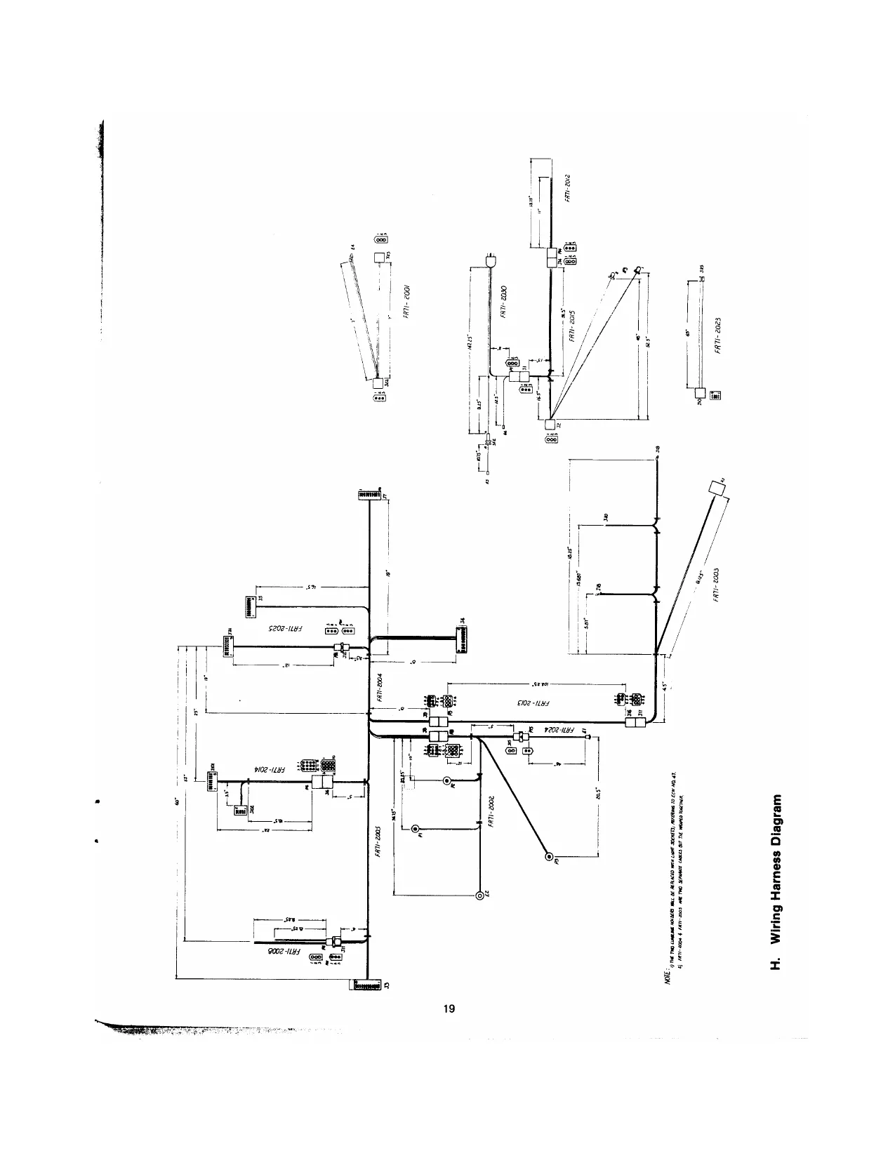
This page is a drawing, shown as the original scan.
- Wiring Harness Pinout Table
Harness Connector From To Wire Signal
| Power Supply | J1 (3-pin | Jt | J2-4 | 18” black 18 ga |
| AC input | maie Molex) | Hot | |
| Jat | J14-4 | 33" black 18 ga | |
| J1-2 | J2-2 | 18" white 18 ga |
Ground
| J1-2 | J14-2 | 33” white 18 ga |
| J1-3 | J2-3 | 18" green 22 ga |
Earth ground
| J1-3 | J14-3 | 33” green 22 ga | ||
| Light Harness | J2 (3-pin | J2-1 | E3-1 | 51" black 18 ga | Hot |
AC input female
| Molex) | J2-2 | E3-2 | 39” white 18 ga | Ground | |
| Main Harness | J3 (12-pin | J3-1 | Je12 | 40" black 18 ga | Ground |
Power Supply | male Molex)
| Output | J3-2 | S122 | 63's" yel-org 18 ga |
+12 VDC audio
| J3-2 | J12-3 | 63's" yel-org 18 ga |
| J3-3 | Jat | 68" yellow 18 ga |
+12 VDC logic
| J3-3 | Je-11 | 40” yellow 18 ga |
| J3-4 | J6-10 | 40" brown 18 ga |
—5 VDC
| J34 | J4-5 | 68" brown 18 ga | |
| J3-5 | J12-1 | 63%" white 18 ga | | —VDC audio |
| 53-6 | Ja-4 | 68" wht-red 18. ga_| | ~12 VDC logic |
J3-7 to UNUSED J3-11
| J3-12 | J4-7 | 68" black 18 ga |
Ground
| J3-12 | J11-3 | 9" black 18 ga | ||
| Main Harness | J4 (9-pin | J4-2 | J11-3 | 67" red 18 ga | +5 VDC |
Mother Board | female
| Power | Molex) | J4-3 | J11-3 | 67” black 18 ga | Ground |
54-6 and UNUSED J4-9
| 14-8 | J14-2 | 67" red 18 ga | +5 VOC |
|. Wiring Harness Pinout Table (Continued)
Harness Connector From To Wire Signal
| Main Harness | JS (9-pin | J5-1 | J6-7 | 2 ga | yel | Composite sync |
| Mother board | female | J5-6 | J6-8 | twisted pair | bik | Ground |
Video Molex)
| J5-7 | J6-1 | x. 22 ga | red | Red video | |
| J5-4 | J6-2 | twisted pair | bik | Ground | |
| J5-8 | J6-5 | 46%" 22 ga | blu | Blue video | |
| 5-4 | J6-6 | twisted pair] bik | Ground | |
| J5-9 | J6-3 | 46%" 22 ga | grn | Green video | |
| J5-6 | J6-4 | twisted pair] blk | Ground | |
| Main Harness | J6 (12-pin | J6-9 | Ja | 39" red 18 ga | +5 VOC |
Monitor female
Molex)
| Main Harness | J7 (10-pin | s7-4 | J9-5 | 46" green 22 ga | Anti-siam switch |
Daughter flat female
Board Molex) 7-2 J8-9 46" It. blue 22 ga Pitch (vertical)
Direction
| J7-3 | J8-8 | 46” violet 22 ga | Yaw (horizontal) |
| 7-4 | 8-7 | 46" grn-red 22 ga | Forward-reverse/thrust |
| J7-8 | J8-6 | 46" black 22 ga |
Ground
| J7-5 | J9-2 | 46" black 22 ga |
| J7-6 | 8-5 | 46" red 22 ga |
+5 VDC
| J7-6 | Jo-1 | 46" red 22 ga | |
| J7-7 | J9-4 | 46" wht-blk 22 ga | Coin (norm. open) |
| J7-8 | J9-3 | 46" yel-blk 22 ga | Coin (norm. closed) |
| w7-9 | J8-2 | 46" blue 22 ga | Start |
| J7-10 | J8-1 | 46" orange 22 ga | Fire |
Main Harness | J8 (9-pin See J7 Control Unit male Molex)
Main Harness | J9 (6-pin See J7 Coin Mechanism | male Molex)
| Main Harness | J10 (4-pin | J10-2 | Spade | 63" 22ga | vit | Speaker |
| Daughter | female | J10-3 | Connectors || twisted pair | wt-gn | Speaker |
Board—Speaker | Molex)
Wiring Harness Pinout Table (Continued)
Harness Connector From To Wire Signal
| Control Unit | P8 (9-pin | PB-1 | J15-1 | 17" orange 22 ga | Fire |
Harness female
| Molex) | P8-2 | E2-C | 48°" blue 22 ga | Start |
P8-3 and UNUSED Pad
| P8-9 | PIR | 4a" It. blue 22 ga | Pitch (vertical) | ||
| P8-5 | P3-R | 3212" red 22 ga | +5 VDC | ||
| 8-6 | 115-2 | 17” black 22 ga | Ground | ||
| P8-7 | P3-M | 322" grn-red 22 ga | Forward-reverse/thrust | ||
| P88 | P2-R | 27" violet 22 ga | Yaw (horizontal) | ||
| Control Unit | 15 (2-pin | J15-2 | E2-A | 4194" black 22 ga | Ground |
Fire Button female Molex)
| Control Unit | E2 (903, | See P8 |
Start Button switch)
| Control Unit | P1 (50K | Pi-M | P2-M | 27%" red 22 ga | +5 VDC |
Pitch Pot potentiometer) (vertical)
| Control Unit | P2 (50K | P2-M | P3-R | 35'2" red 22 ga | +5 VDC |
Yaw Pot potentiometer) (horizontal)
| Control Unit | P3 (50K | See P8 |
Thrust Pot potentiometer) (speed)
| Main harness | J11 (3-pin | See J4, JE |
+5 Power male Molex) Supply
Main Harness —_| J12 (3-pin See J3 Audio Power female Molex)
AC Power and =| J14 (3-pin See J1 Light Harness | female Xfmr Input Molex)
1, Wiring Harness Pinout Table (Continued)
TREE oo eee
i Harness Connector From To Wire Signal
AC Power and | E3 (2 See J2 Light Harness | LUMILINE
LUMILINE fixtures
oR OR 15 W bulbs 2 Bulb fixtures)
| Control Unit | P15 (2-pin | P15-1 | E1-C | 46" orange 24 ga | Fire |
Harness male Molex)
| Fire Button | P15-2 | E1-A | 46" black 24 ga | Ground | |
| Monitor Video | P6 (12-pin | P6-1 | J101-1 | 22" 22ga | red | Red in |
| Harness | male Molex) | P6-2 | J101-2 | twisted pair | blk | Ground |
Monitor
| Connector | P6-3 | J101-3 | 22" 22.ga_ | grn | Green in |
| P6-4 | J101-4 | twisted pair | bik | Ground | |
| P6-5 | J101-5 | 22" 22ga | blu | Blue in | |
| P6-6 | J101-6 | {twisted pair | bik | Ground | |
| P6-7 | J101-7 | 22" | 22a | yel | Composite sync |
| 6-8 | J101-8 | twisted pair | bik | Ground | |
| P6-9 | J102-1 | 22" red 18 ga | +5 VDC | |
| P6-10 | J102-3 | 22" brown 18 ga | -5 VDC | |
| P6-11 | J102-5 | 22" yellow 18 ga | +12 VDC logic | |
| P6-12 | J102-2 | 22” black 18 ga | Ground |
Monitor Video _ | J101 (8-pin See P6 harness female water Video Signal Molex)
Monitor Video | J102 (-pin See P6 Harness female wafer Power Connector | Molex)
| * | +5 V Power | P11 (3-pin | Pitt | Power |
Supply female Supply
| 4 | Molex) | P1t-2 | PCB | Bi" red 18 ga | +5 VDC |
HVE P1t-2
P11-3 Power
Supply 94" black 18 ga Ground
P11-3 PCB -VE
1, Wiring Harness Pinout Table (Continued)
Harness Connector From To Wire Signal Supply male Molex) pin 4
| Power | P14 (3-pin | P1441 | xfmr | 11" black 18 ga | Hot |
Transformer
| Input | P14-2 | ximr | 11” white 18 ga | Ground |
pint
| P14-3 | Xfmr | 13%" green 22 ga | Earth ground |
gnd
| Module Inter- | | P9 (6-pin | P9-t | J16-1 | 102!" red 22 ga | +5 VDC |
connect Exten- | female sion Harness Molex)
| P9-2 | J16-2 | 102%" black 22 ga | Ground |
| P9-3 | J16-3 | 102'2" yel-blk 22ga__| | Coin (norm. closed) |
| P94 | J16-4 | 102'2" wht-bik 22. ga__| | Coin (norm. open) |
| POS | J16-5 | 102%" green 22 ga | Anti-siam |
P9-6 UNUSED
| Module | 116 (6-pin | See P9 |
Interconnect Male Molex)
Extension Harness Coin Door
| Coin Door | }J17 (6-pin | J17-1 | Coin | 13%" black |
| Harness | female | Cntr | ||
| Door Connector | |Molex) | bottom | ||
| J17-2 | J19 | 22" black 22 ga | Coin (norm. closed) |
spade cnx
| J17-3 | 18 | 17%" yel-bik 22 ga | Coin (norm. closed) |
spade cnx
| J17-4 | Coin | 13%" black |
Cntr top
| J17-4 | 18 | 17%" wht-blk 22 ga__| | Coin (norm. open) |
spade onx
| 17-5 | J20 | 21%" green 22 ga | Anti-slam (norm. open) |
pigtail
17-6 UNUSED
|. Wiring Harness Pinout Table (Continued)
Harness Connector From To Wire Signal
| Coin Door | J18 (3 push- | J18 | J19 | 194" wht-blk 22 ga | Coin (norm. open) |
| Harness | on connectors) | norm | spade |
Coin Drop open
| J18 | J19 | 19%" orange 22 ga | Common |
common _| spade
| Coin Door | J19 (3 push- | J19 | J20 | 8%" black 22 ga | Coin to common |
| Harness | onconnectors | norm. | common | (norm. closed) | ||
| Coin Drop | closed | pigtail | |||
| Coin Door | J20 (2 bare | See J17, |
Harness ends, soldered) | J19 Vibration
| Audio Power | P12 (3-pin | P12-1 | J21-4 | 12” white 18 ga | -12 VDC audio |
Harness male Molex)
| Power | P12-2 | (J21-9 | 12” yel-org 18 ga |
+12 VDC audio
| P12-3 | Jatt | 12” yel-org 18 ga |
| Audio Power | J21 (9-pin | See P12, |
Harness female wafer Power Molex)
| 110/220 V | J22 (3-pin | J22-4 | J23-1 | 7” black 22 ga |
| Bifurcated | male Molex) | Hot | ||
| AC | J22-1 | 4-1 | 7” black 22 ga |
Cable
| 122-2 | J23-2 | 7" white 22 ga |
Ground
| 22-2 | 4-2 | 7" white 22 ga |
| 122-3 | 123-3 | 7” green 22 ga |
Earth ground
| J22-3 | 4-3 | 7" green 22 ga |
| 110/220 V | J23 (3-pin | See J22 |
Bifurcated female AC Cable Molex)
| 110/220 V | 4 (TFB-B | See J22 |
Bifurcated butt AC Cable connector)
| AC Line | Pt (3-pin | Pit | interlock | |12" black 18 ga | Hot |
Cord female spade
Power In Molex)
| P1-2 | AC plug | 140" white | Ground | |
| P1-3 | AC plug | 140" green | Earth ground | |
| AC Line | SFE | SFE-A | AC plug | a7" |
Cord 3 amp
Fuse SFE-B ES 10%" red
interlock
J. Selected Parts List
Complete Assemblies
Part QTY/Game_ Exidy Part #
| Mother Board | 1 | FR77-3175 |
| Daughter Board* | 1 | FR77-3185, |
| Color Monitor, | 1 | FR79-2301 |
PHOTOTEK oR OR oR
| Color Monitor, | 1 | FR79-2307 |
TEKNIKA
“Early model daughter boards must be ordered with an audio power harness.
Isolation Transtormers for TEKNIKA Monitor
Part QTY/Game Exidy Part #
Triad N67A 1 OR oR Triad N74A 1 OR OR
| Stancor GSD 250 | 1 | FR63-4029 |
OR oR Stancor P8622 1 OR oR Standard Magne- 1 tics (open frame)
Power Supply
Part QTY/Game Exidy Part #
| Adtech 5 V 6 amp | 1 | FR78-3001 |
Supply
| PC Board, As- | 1 | FR77-3195 |
sembled
| Transformer T911 | 1 | FR63-4028 |
OR OR oR
| Transformer T893 | 1 | FRE3-4025 |
Wiring Harnesses
Part QTY/Game Exidy Part #
| Speaker Pigtail | 1 | FR71-2001 |
Harness
| Control Unit | 1 | FR71-2002 |
Harness
| Coin Harness | 1 | FR71-2003 |
| Main Harness Ass'y | 1 | FR71-2005 |
| 5V Pigtail Harness | 1 | FR71-2008 |
| AC Input Harness | 1 | FR71-2012 |
to Power Supply
| Interconnect | 1 | FR71-2013 |
Extension Harness
Monitor Interface 1
| Harness, early* | 1 | FR71-2014-14, |
PHOTOTEK OR OR oR Monitor Interface
| Harness, TEKNIKA | 1 | FR71-2014-1B |
and Late PHOTOTEK
AC Power and Light 1 FR71-2015
Harness
| Bifurcated AC | 1 | FR71-2023 |
Cable
| Fire Button | 1 | FR71-2024 |
Harness
| Audio Power | 1 | FR71-2025 |
Cable**
| TEKNIKA | 1 | FR71-2028 |
Monitor*** Interface Cable
| AC Line Cord and | 1 | FR71-2030 |
Fuse
*Soldered to Monitor PC board
**Soidered to early model daughter boards; Molex connected to later model boards. When ordering, specity early or later model. This harness must be ordered when replacing an early model daughter board. ***Not needed for games equiped with the PHOTOTEK monitor.
J. Selected Parts List (Continued)
Pre-Programmed ICs Mother Board
Part Location —_Exidy Part #
| 6331 PROM or | 7A | FR48-2153 |
equivalent
| 6331 PROM or | 8A | FR48-2154 |
equivalent
There are three sets of STARFIRE program chips. Each STARFIRE game has just one of these sets:
- 10 EPROM chips in columns 1 and 2 of the daughter board. Each EPROM has a paper sticker on the back.
- 10 ROM chips in columns 1 and 2 of the daughter board. The chips do nof have
paper stickers, and there is no chip in socket
1F. ¢ 11 ROM chips in columns 1 and 2 of the daughter board. The chips do not have paper stickers, and there is a chip in socket 1F.
These sets are not interchangeable; if you must replace a program chip, be certain to order the correct replacement.
Pre-Programmed ICs Daughter Board
Part Location _Exidy Part #
( 1A FR48-9013
2a FR48-9014
18 FR48-9015
28 FR48-9016 STARFIRE
| game program, J | 1c | FR48-9017 |
10 EPROM set 2c FR48-9018
1D FR48-9019
20 FR48-9020
1E FR48-9021
2E FR48-9022
Part Location —Exidy Part #
1A FR49-1026
2a FR49-1027
18 FR49-1028
28 FR49-1029
| STARFIRE | 1c | FR49-1030 |
game program
| 10 ROM set | 2c | FR49-1031 |
1D FR49-1032
20 FR49-1033,
1E FR49-1034
2e FR49-1035
1A FR49-1015
2A FR49-1016
1B FR49-1017
28 FR49-1018 STARFIRE
| game program, | 1c | FR49-1019 |
11 ROM set 2c FR49-1020
1D FR49-1021
2D FRa9-1022
IE FR49-1023
2E FR49-1024
1F FR49-1025
Control Unit Parts
Part QTY/Game Exidy Part #
Printed Control Panel
Steering Yoke FR68-6040
FR92-1005
J. Selected Parts List (Continued)
Control Unit Parts Continued Part QTY/Game —Exidy Party
| Yoke Cover Plate | 1 | FR68-9015 |
| Base Bracket | 1 | FR68-9004 |
| Flanged Bearing | 2 | FR74-5100 |
NF-1210-32
| Steering Tube | 1 | FR92-1002 |
| Steering Coliar | 2 | FR92-1003 |
| Steering Stop | 1 | FR92-1010 |
Centering Spring 2 Stock Spring #273S 9/16 diam x 4L
Stainless Steel Bolt 1 9/8-24 « 1% Lb
| Pushbutton Switch, | 2 | FR72-3022 |
#930
| Control Potentio- | 3 | FR54-5027 |
meter (Pot), 50 K ohm Allen-Bradley (metal can) OR oR oR
| Control Potentio- | 3 | FR54-5028 |
meter, (Pot), 50 K ohm CTS {plastic body)
| Square Shaft | 1 | FR92-1001 |
Bearing, Nylon
| Yaw (Horizontal) | 1 | FR68-9001 |
Pot Bracket
| Yaw Pot Square | 1 | FR92-1004 |
Shaft
| Pitch (Vertical) Pot | 1 | FR6B-9002 |
Bracket
| Pitch Link | 1 | FR68-9003 |
Pitch Link Spring ‘Stock Spring #248S 11/32 diam * 2% L esiihin a einasicembecten,
Part Qty/Game —_Exidy Part#
Cotter Pin 3/32 x %4L 1
| Thrust Bracket | 1 | FR68-9005 |
| Thrust Pivot | 1 | FR68-9006 |
| T-handle | 1 | FR92-1006 |
| Grooved Pin (type | 1 | FR74-5151 |
C) diam x 2" Bearing Engineering
| Grooved Pin (type | 1 | FR74-5152 |
C) "4 diam * 94" Bearing Engineering
| T-handie Sleeve | 1 | FRQ2-1012 |
Thrust Rail al FR68-9007
Spring, Thrust Rail 2 Century #C514
| Shoulder Screw, | 2 | FR74-5156 |
Thrust Rail tu diam 1 L 10-32 Slot Head, Bearing Specialties #PL-25
Cabinet Parts Video Module
Part QTY/Game Exidy Part #
| Logo Plastic Panel | 1 | FR75-4003 |
| CRT Display Plastic | 1 | FR75-4004 |
Panel
| Formed Paper | 1 | FR76-1055 |
Bezel
| Vinyl Side Panel, | 1 | FR76-1045 |
Planet & Fighters
J. Selected Parts List (Continued)
Cabinet Parts, Video Module Continued Part Qty/Game —_Exidy Part #
| Vinyl Side Panel, | 1 | FR76-1675 |
Explosion
| 8” 8 ohm 10 oz | 1 | FR62-7050 |
Speaker
| | 7 speaker Grit | 1 | FR68-9016 |
| LUMILINE Lamp* | 1 | FR70-6023 |
| LUMILINE Lamp | 2 | FR70-6024 |
Fixture*
| PC Board Mount | 1 | FR76-1054 |
“Early models only. Later models have two 15W bulbs and bulb fixtures. Cabinet Parts, Passenger Module
Part QTY/Game Exidy Part #
| P/M Plastic Panel | 1 | FR75-4005 |
| Vinyl Side Panel, | 1 | FR76-1062 |
Fighter
| Viny! Back Panel, | 1 | FR76-1064 |
STARFIRE Logo
| Vendall Double | 1 | FRG66-4003 |
Coin Door
| Coin Box | 1 | FR68-9014 |
| Shipping Carton | 1 | FR76-1054 |
Brace
| U-bracket (Cabinet | 2 | FRE8-9012 |
Clip)
200s] 17-¥000-0cu4 |
ASVGSNIL OCIA 830 | 30vd|_WVHOVIG 19071! W3LSAS.
“ONL AGIXS AS
= zaee eee Bee vets
EXIDY INC. SYSTEM || LOGIC_DIAGRAM PEGE 20F 6]
CENTRAL PROCESSOR
FR30-0004-AT | s.oce
rei 15ROD Ps, @ ROD SITS EXiDY INC. TSYSTEM IILOGIC DIAGRAM PAGE 30F8] MEMORY TIMING L_ FR30-0004-17 _[s.ocs |
ge
oct A
lg 28s a2 fag2y Net0-w@- Bg e¥2t aF9E R232 i] te ee
43% 089 Resv-ne2 Nesn-0~ Wez2tay9s 95494 NEOoRS 3 3 cd
Nej0-0n EPC RE Prag
ae!
z J pT: Ne an-on ese 8Tas EXIDY INC, SYSTEM 11 LOGIC DIAGRAM [PAGE 4 OF 6] DATA PROCESSING [_FR30-0004-1T _ [5.006
This page reads as a drawing: its text was drawn rather than typeset, and comes out in fragments. See the original scan.
3003] _1-¥000-064s THONGN ew ONISSIOOUd NOD [esd WveOvIG SOOT WaISKST — T
neamonng
SONT AGIXS:
wong oanasd [8202 aod WVYOVIG 31907 1! WALSAS. “ONL ACIXS. ‘ss | _c/-¥000-0eu7 J pasn yous; 13S HLSISTHL 2310N
70H ed Ta. 1 ne A HS Wi we “8 4 rs é oe £ sires 4 ie 1H)
rt) s s $ 2 tet va : i ia z Z ae
EXIDY INC. fe} fo) Pp N c (e} N N E c T ° R Pic. foozzwo >—oW0 Oey
GREEN OUTPUT
[SYSTEM It LOGIC DIAGRAM PAGE BOF 6]
CONNECTORS ano VIDEO OUTPUT
I FR30-0004-/ J [s.0cs
Reanene eretrs 3848883 a easse 5896858 Re anened. & %
NOTE:
ae 2200pF with SOK pots [EXibY INC. ___—_—*([STARFIRE SCHEMATICS PAGE 1OFS] SFaSsae Resumen! sassasd : INPUTS /OUTPUTS FR30-0005: Ua Su
SHUNT DIP CONFIGURATIONS cpiyone & used depending onmemory
P @ox \omox Reverwaseat RAAWTQQIIT
SHUNT DIPS: TYPE
3FA (oone metct) oF 3FD
ROM or PROM
Th276 1183168 T2516 lotel 2716 Intel 236E, RockwellZ3168 Necorsaary only if ‘configurations Bor wwere previoushy sed
EXIDY INC. STARFIRE SCHEMATICS PROGRAM MEMORY FR30-0005-iF
at EXIDY INC.
[STARFIRE SCHEMATICS PAGE 30F 5]
AUDIO
] FR30-0005-IF
STARFIRE SCHEMATICS PAGE 40F5| [__FR30-0005-1F | s.0%6
-o0a-2 VOZZWOrFOa LEROY ING) STARFRE_-SCHEMATICS _PRCE SOFA] Dozzworoe FR30-0005-iF r