Red Baron DP-169-1st-01B
Red Baron (revised hardware) (Atari, 1980) · Drawing Package · 1 pages · original scan
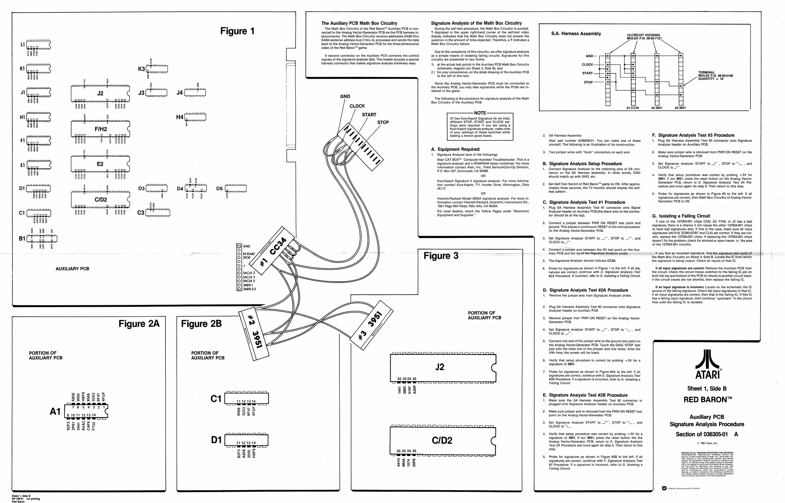
The Auxiliary PCB Math Box Circuitry Signature Analysis of the Math Box Circuitry Figure 1 ‘The Math Box Ceuty ofthe Red Baron” Auxillary PCB Is con During the seltest procedure, the Math Box iru is quizzed. nected tothe Analog VectorGenerator PCBviathe PCB harnessin. __T aeplayed In tho upper righthand comer of the selest video
| torconectr. the Man ox Creu eclvesadcrsses EABD hvu | play ndcte ta the Math Box Crelty doesnot anawer the | S.A. Hamess Assembly | wzemeur Housina, |
| EAbs extemal adsress bus Oth), processes and sends the data | question | the amount of tie expected. There, a Tincates a | : |
back tothe Analog VectorGeneator PCB forthe teecimensional Math Box Creu fale video ofthe Red Baron™ game, ue tothe compexty ofthis cicuty, we offer signature analysis
| ‘A second connector onthe Auxllay PCB connects the control | _as.a simple means of folting falling celts, Siature fortis | enp— | fe | fs} | |||
| 3 | signals ofthe signature analyer(SA) nis hssder accepts a special | crcl are presented in wo foms | ial | ||||
| a | Ss | hamess connector that makes signature ans xtreme eas. | 4) | the actual eat pots the Aueary PCB Math Box Gleutry | crock} | fe | C |
kal.” schematic diagram (on Sheet 3, Side 6), and
| re | 2) foryourconvenence on the detail rang ofthe Auxiliary PCS | evant | Fe | 4 | TERMINAL | ||
| H | | | tothe eto ths text | fs] | ic | a | Suanty 95 | |
| i | i | TOP. | +t | imal | te | ||
| : | i | 3 | Since the Analog VectorGenerator PCB must be connected to | [ss | H | cs | |
| e | o | bo | = 5 = | | | the Auxiliary PCB, you may take signatures while the PCBs are in- | 1 | — |
| * | 7 | t | stalled in the game. | ||||
| J2 | w3[? | J4U | j | GND | . | H | : |
| wuus | Pare | 7 | | | ‘The following is the procedure for signature analysis of the Math | | | ry | |
| 2 | i | 0x Greuty ofthe Aunliny POS: | H | H | |||
| ba | & | 8888 | mcc34 | #25051 | 135951 |
Fa s NOTE
| LL | es | A | } | Of two Kurz Kasch Signature ls we tried, |
| ye | : | ; | Giferet STOP, START and CLOCK set |
Tie tne cides fou Se sakes FIH2 Kure Kaoch signature analyzer, make note
| pares | peered | testing a known good board | 2. | SAHamess Assembly | F. | Signature Analysis Test #3 Procedure |
| FIs ou | Tie | EE | Gane | ‘Atari part number A09689601. You can make one of these | 1. | Plug SA Harness Assembly Test K3 connector onto Signature |
| = | Yours The following isan Ilstaion ots contruction, | Analyzer header on Aullry PCB |
i - Ee Required:
| aE ui | ‘A. | Equipment | Required: | 3, | Two jumper wires with “hook” connectors on each end. | 2. | Make sure jumper wire is removed from PWR ON RESET on the |
| 1. | Signature Analyzer (ne of he folowing | Psmregteeuss ee fa |
‘Alar CAT BOX ComputerAsssted Troubleshooter. This is a ‘signature analyzer and a ROMIRAM tester combined. For more
information contact Atari, Inc., Field ServicelCoin-Op Division,
P.O. Box 427, Sunnyvale, CA 94086, on Kuz-Kasch Signature It signature analyzer. For more informar tion contact Kurz-Kasch, 711 Hunter Drive, Wilmington, Ohio 45117. oR Howlett Packard Model S004A signature analyzer. For more information contact Hewlett-Packard, Scientific Instruments Div, 1601 Page Mill Road, Palo Alto, CA 94204, For local dealers, check the Yellow Pages under “Electronic Equipment and Supplies.” B. Signature Analysis Setup Procedure Connect Signature Analyzer to the matching pine of SA con: nector on the SA Hamess assembly. In other words, GND Should match up with GND, ete
- Set Self-Test Switch of Red Baron™ game to ON. After approx Imately three seconds, the TV monitor should display the selt test pattern.
| C. | Signature Analysis | Test #1 Procedure |
Plug SA Hamess Assembly Test #1 connector onto Signal ‘Analyzer header on Auxlary PCB (the black wie on the connec: tor should be atthe top).
Connect a jumper between PWR ON RESET test point and
‘round, This places a continuous RESET to the microprocessor
‘on the Analog Vector-Generator PCB.
- Set Signature Analyzer START to _/~, STOP to_/~, and CLOCK to. 3, Set Signature Analyzer START to _/~, STOP to™\_, and CLOCK to_~
- Verity that setup procedure was correct by probing +SV for 3951. If not 3851, press the reset button on the Analog Vector- Generator PCB, retum to D. Signature Analysis Test 24 Pro- ‘cedure and once again do step 5. Then return to this step.
- Probe for signatures as shown in Figure #3 to the left. If all signatures are correct, then Math Box Circulty of Analog Vector Generator PCB is OK.
G. Isolating a Failing Circuit
It one of the 137004001 chips CiD2, £2, FIH2, or J2 has a bad signature, there is @ chance It will cause the other 137004001 chips to have bad signatures also. If this is the case, make sure all input signatures (A0-A19, EDBOEDB? and CLK) are correct. If they are cor. rect, replace the 137004001 chips. If replacing the 137004001 chips
doesn’ fix the problem, check for shorted or open traces in the area
Gl of he 197008001 eeu,
| iB | 4. | Connect a jirier wie between the PU test pont onthe Ave: | |||
| lS | : | : | Mary PCB andthe tof ne Sigal analyz probe | 1 you ind an inconect | sonar, fod the signature test onto |
| 8 | igure | arose! ts | erent | ||
| Ie | 5. | The Signature Analyzer should indicate C034 | the signature fs being cutpu: Check al input of hat IC | ||
| AUXILIARY PCB | 8 | 6. | Probe for signatures as shown In Figure 1 tothe lft fal sig | 1a Input statues are correct: | Remove the Auxary PCB from |
| IS | atures aro corect, continue wit B. Skgratue Anavse Test | the cvcul. Cheek te cet races common fo the tain opin on | |||
| 8 | 124 Procedure. | inconect, ler toG Isolating’ Fling Greult. | both the topand bottom ofthe PCB for sors to anther eu ace. |
iS tthe ete traces are not shotee, then repace the fling IC. lo
| ; | 1 an input | signature i income: Locate onthe schematic the 1 | |
| lo | D. | Signature Analysis Test #2A Procedure | source of io fang signature Check to nut signatures of hat |
| ful | ase Gi orp a omy Signcare aveorecbe | ial input signatures are comes, then that ste fang | Tt tis 1G |
has a failing input signature, then continue “upstream” inthe circuit
flow until the failing IC is isolated
- Plug SA Harness Aésombly Test #2 connector onto Signature ‘Analyze header on Auxillary PCE. PORTION OF " cif AUXILIARY PCB ‘3. Remove jumper from PWR ON RESET on the Analog Vector- Generator PCB. Figure 2A 4, Set Signature Analyzer START to_/~, STOP to-\_, and CLOCK to_~.
‘Connect one end ofthe jumper wire to the ground test point on
the Analog Vector-Generator PCB. Touch the DIAG ‘STEP’ test ad with the other end of the jumper wie five times. After the fifth time, the screen wil be blank.
Verify that setup procedure is correct by probing +5V for a signature of 3951,
- Probe for signatures as shown in Figure #2A to the left. If all ie signatures are corres, continue with E Signature Analysis Test #28 Procedure. Ia signature is incorrect, refer to G. Isolating @ Falling Circuit PORTION OF PORTION OF AUXILIARY PCB AUXILIARY PCB
m Sheet 1, Side B . Signature Analysis Test #2B Procedure Make sure the SA Harness Assembly Test #2 connector is RED BARON™ plugged onto Signature Analyzer header on Auxiliary PCB. Aas6
1011121314 ofp HOF9 afr 9569 cof 3u53 nf 9F47 fy 4FUF
- Make sure jumper wie is removed from the PWR ON RESET test point on the Analog Vector-Generator PCB. Auxiliary PCB 2 Sat irate Anaiaer START 12/~, STOP 19 and Signature Analysis Procedure
| 4. | Verify that setup procedure was corect by probing +5V for a | Section of 03630501 | A |
signature of 3961. If not 3951, press the reset button the the ‘Analog VectorGenerator PCB, return to D. Signature Analysis Test 24 Procedure and once again do step 6. Then return to this, step, Al
euac’ caps F722 2P61 3441
c/D2
- Probe for signatures as shown in Figure #28 to the left. fall Zgee signatures are correct, continue with F. Signature Analysis Test 858 #3 Procedure. Ita signature i incorrect, refer to G. Isolating @ Failing Cirut
| 6 SY