Lunar Lander DP-136-1st-01B
Lunar Lander (rev 2) (Atari, 1979) · Drawing Package · 1 pages · original scan
POWER INPUT
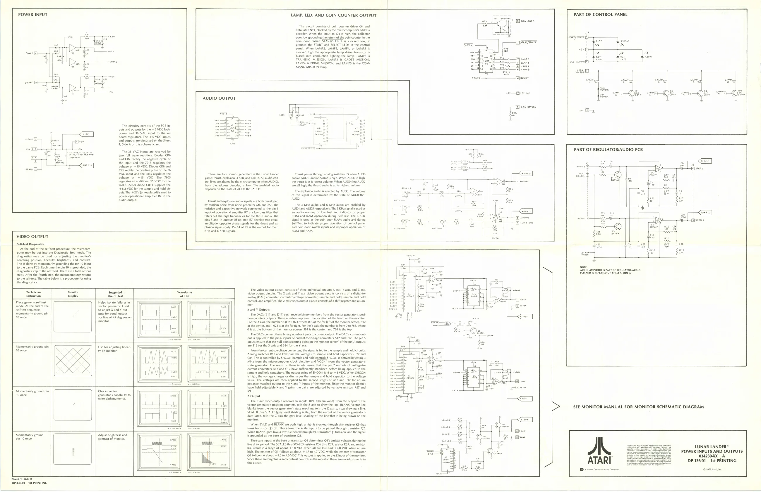
‘This circuitry consists ofthe PCB in-
puts and outputs forthe +5 VOC logic
power and 36 VAC input to the on board regulators. The +5 VOC inputs and outputs are discussed on the Sheet 1, Side A of this schematic set
The 36 VAC inputs are received by two full wave rectifiers. Diodes CRE ‘and CR7 rectify the negative cycle of the input and the 7915 regulates the voltage at ~15 VDC. Diodes CRB and ‘CRO rectty the positive pulse ofthe 36 ‘VAC input and the 7815 regulates the voltage at +15 VDC. The 7805 regulates an additional 15 VOC for the ACS. Zener diode CRI supplies the
+82 VDC for the sample and hold cit
uit The +22V (unregulated) is used to
‘power operational amplifier R7 in the ‘audio output
LAMP, LED, AND COIN COUNTER OUTPUT
This circuit consists of coin counter driver Q¢ and
data latch N11, clocked by the microcomputers address
decoder. When the input to Q4 is high, the collector
‘2085 low grounding the return of the coin counter inthe
coin door. When STARTISELECT is clocked low, it ‘rounds the START and SELECT LEDs in the control panel. When LAMP2, LAMP3, LAMPS, of LAMPS. locked high the appropriate lamp driver transistor is biased into conduction lighting the lamp. LAMP2 is TRAINING MISSION, LAMPS. is CADET MISSION, LAMD4 is PRIME MISSION, and LAMPS is the COM. MAND MISSION lamp,
AUDIO OUTPUT
There are four sounds generated inthe Lunar Lander ‘game: thrust explosion, 3 KHe and 6 KH. All audio con- ‘tol ines are altered bythe microcomputer when AUDIO. from the address decoder, is low. The enabled audio depends on the state of AUDO thru AUDS.
‘Thrust and explosion audio signals are both developed by random noise from noise generator Mo and M7. The resistive and capacitive network connected to the pin 6 ‘input of operational amplifier R7 isa low pass fier that filters out the high frequencies for the thust audio. The pins 8 and 14 outputs of op amp R7 develop two equal amplitude, opposite phase signals forthe thust and ex ‘Thrust passes through analog switches PS when AUDO andior AUDI, andlor AUD2 is high: When AUDO is high, the thrust tit lowest volume. When AUDO thru AUD2 ae all high, the thrust audio is tits highest volume
The explosion audio is enabled by AUD3. The volume ‘of ths signal is determined by the state of AUDO thru AUD2
‘The 3 KH audio and 6 KHz audio are enabled by ‘AUD4 and AUDS respectively. The 3 KHz signal is used as. {an audio warning of low fuel and indicator of proper ROM and RAM operation during Sel Test. The 6 KH2 signal is used asthe coin door SLAM audio and during Sel-Test to indicate proper operation of control panel Le aera PART OF CONTROL PANEL
VIDEO OUTPUT
sel Test Diagnostics At the end of the selftest procedure, the microcomputer may be put into the Diagnostic Step mode. The diagnostics may be used for adjusting the monitor's Centering position. linearity, brightness. and contrast. This is done by momentarily grounding the pin 10 input to the game PCB. Each time the pin 10 is grounded. the diagnostics step tothe next test There area total of four steps. After the fourth step, the microcomputer returns to the selftest. The table below is a procedure for using the diagnostics,
Technician Monitor Instruction Display Place game in selftest mode At the end of the sit segue eee 10 once. a plosion signals only. Pin 14 of R7 isthe output for the 3 and coin door switch inputs and improper operation of Ke and 6 KHz signal, ROM and RAM. {sve oe PART OF REGULATORIAUDIO PCB
Helps isolate failures in vector generator, Used
puts for equal output for line of 45 degrees on ‘monitor to adjust X and Y out | | |
Momentarily ground pin 10 once. Use for adjusting linear ty on monitor.
‘Momentary ground pia AW once. checks vector senerator’s capability to ‘write alphanumerics,
‘Momentaily ground pin 10 once,
sheet 1, side B DP-3601 Ist PRINTING Adjust brightness and Contrast of monitor. ‘The video output circuit consists of thee individual circuits X axis, ¥ axis, and Z axis Video output ctcuits. The X axis and ¥ axis video output circuits consists of a digitaltoanalog (DAO) converter, current tovoltage converter, sample and hold, sample and hold contol, and amplifier. The Z axis video output circuit consists. a shift register and a sum
X and Y Outputs ‘The DACS (811 and Dt1) each receive binary numbers from the vector generator’ post tion counters outputs. These numbers represent the location of the beam on the monitor. For the X axis, the number i 0 to 1,023, where Os atthe far left ofthe monitor sereen, 512, atthe center, and 1,023 sa te fr right. Fr the ¥ axis, the number is from 0 to 76, where (0s at the bottom of the monitor screen, 384 isthe center, and 768 isthe top. ‘The DACS convert these binary number inputs to current output. The DAC’s current output is applied tothe pin 6 inputs of current-o-oltage converters A12 and C12, The pin 5 inputs ensue that the null points (esting point on the monitor screen) ofthe pin 7 outputs ate 512 for the X axis and 384 for the Y axis From the currentto-voltage converters, the signal is fed to the sample and hold circuits Analog switches B12 and D12 pass the voltages to sample and hold capacitors C77 and. CBs. This is controlled by SHCON (sample and hold control). SHCON is derived by gating 3 Miz from the microcomputer clock cicuity and VGCK* from the vector generators state generator. The result of these inputs insure that the pin 7 outputs of voltagetocurrent converters A12 and C12 have sufficiently stabilized before being applied to the sample and hold capacitors. The output swing of SHCON is 8 to +8 VDC. When SHCON 's high, the voltage charges or discharges the sample and hold capacitor to the voltage value. The voltages are then applied to the second stages of A12 and C12 for an im ppedance matched output to the X and Y inputs ofthe monitor. Since the monitor doesnt have field adjustable X and ¥ gains, the gains are adjusted by variable resistors R87 and, RO.
Z Output The Z axis vdeo output receives six inputs. BVLD (beam valid), from the output ofthe vector generators postion counters, tells the Z axis to draw the line. BLANK (vector line blank) from the vector generators state machine, tells the Z axis to stop drawing a line. SCALEO thru SCALES (rey level shading scale, from the output of the vector generator’ ‘data latch tells the Z axis the grey level shading of the line that is being drawn on the monitor. \When BVLD and BLANK are both high, a high is clocked through shift egister K9 that tums transistor Q3 off. Ths allows the scale inputs to be passed through Wansistor Q2. ‘When BLANK goes low, a low is clocked through K9, transistor Q3 turns on, and the signal is grounded at the base of tansistor Q2. The scale inputs atthe base of transistor Qt determines Qs emitter voltage, during the line draw period. The SCALEO thru SCALES resistors R36 thru R39,sistor R35, and resistor R40 result in a range of about +10 VOC when all are low and +40 VOC when all are high. The emitter of Q1 follows at about +1.7 to 47 VOC, while the emitter of transistor Q2 follows at about + 1.0 to 4.0 VOC. This output is applied tothe Z input of the monitor. Since there are brightness and contrast controls inthe monitor, there are no adjustments in this circuit Nore [AUDIO AMPLIFIER Is PART OF REGULATORIAUDIO (PCB AND IS REPEATED OW SHEET 1, SIDE.
5 SEE MONITOR MANUAL FOR MONITOR SCHEMATIC DIAGRAM
LUNAR LANDER™ POWER INPUTS AND OUTPUTS 034230-XX A 1 ATARI DP-136-01 1st PRINTING Ore conmacains Campa, (©1979 Aa ne