Asteroids Deluxe Caberat DP-173-1st-01B
Asteroids Deluxe (rev 3) (Atari, 1980) · Drawing Package · 1 pages · original scan
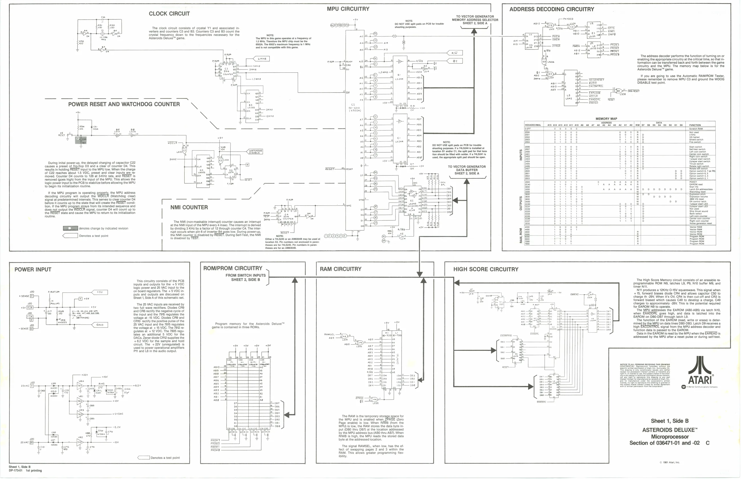
CLOCK CIRCUIT
Asteroids Deluxe™ gam
POWER RESET AND WATCHDOG COUNTER
ese eee Se 8 BE
MPU CIRCUITRY
| ADDRESS DECODING CIRCUITRY
A320, pe es Lt eb res fe rap OTs
atk ‘a
During inital power-up, the delayed charging of capacitor C22 ‘causes @ preset of flipfiop D3 and a clear of counter D4, This
Tesults in holding FESET input tothe MPU low. When the charge
‘of C22 reaches about 1.5 VOC, preset and clear inputs are re-
moved. Counter D4 counts to 128 at KHz rate, and RESET is
removed (goes high) from the input of the MPU. This allows the Togic power input to the PCB to stabilize before allowing the MPU 10 begin its initialization routine,
UF the MPU program is operating propery, the MPU address decoding circuitry will output the (Watchdog clear) signal at predetermined intervals. This serves to clear counter D& before it Counts upto the state that wil create the RESET condi tion. Ifthe MPU program stays from its intended sequence and does not qutput the signal, counter D4 will count up (0 th ‘slate and cause the MPU to return to its Initiation routine.
THEE cerotesenange oy ince revision <a) Denotes a test point cere TO VECTOR GENERATOR
“ nore MEMORY ADDRESS SELECTOR
e898 20 NOT USE spit pads on PCB for tobe ‘SHEET 2, SIDE A The clock circuit consists of ental Y1 and associated in ocr eed verters and eounters C3 and B3. Counters 03 and 83 count the em
| crystal frequency down to the frequencies necessary for the | Nore: | nels | ap. |
‘The MPU nts oa opera t requoncy of 7 psemtargemeered be ® 0 aul texan Te ooare muti geno et Me “ “ as
Sp sana <
Load 5
ene (sea) 3
&
1s
Me 7
| a | ies | ao | Note | |
| poz) | SNOT | USE spt pas on PB for tote | ||
| Soot | prow | tat | ad at | |
| | | ri | Lena | | Stamhehtaee ch wecgmpetere ow | ¢ |
| ‘cm enoud be tnd | sco | asa | § | |
| ne | 10a] | sua the propa opt pa stb open | 2 |
—_ ov TO VECTOR GENERATOR Rater —Adecser pa 7 SHEET 2, SIDE A
a
| —, | —, | — | — | ond | g |
| NMI COUNTER | a | 5 |
The NMI (non-maskable interrupt) counter causes an interupt al atthe NMlinput ofthe MPU every 4 see: The interupt is derived a by dividing 9 KHs by a factor of 2 through counter Cs. The inter 7
| fp accure when pn B | tive Ba gam ow. During power sp | z |
the NMI countgrlsgisabled by RESET. During Sel Test, the NM 000000 =
| is oisabied by TEST | ‘hrs 74.585 oan ASSES my | Dune at | z |
Jocation EZ Pin numbers not enclosed in paren Es tree fr tals Bn nao npr tesa fren soo
POWER INPUT
Sheet 1, Side B DPA7301 ‘st printing This circuitry consists of the PCB Inputs and outputs for the +5 VDC logic power and 25 VAG input to the (on board regulators. The + 5 VOC inputs and outputs are discussed on Sheet 1, Side A of this schematic set. ‘The 25 VAC inputs are received by two full wave rectifier. Diodes CRS ‘and CR8 rectly the negative cycle of the Input and the 7915 regulates the voltage at -15 VDC. Diodes CRS and CRW rectity the positive pulse of the 25 VAC input and the 7815 regulates the voltage at + 15 VDC. The 7812 re- (ulates at + 12 VOC. The 7805 regufates an additional § VDC for the DACs. Zener di +82 VOC for the sample and hol circuit. The + 22V (unregulated) is Used to power operational amy Pit and LB in the audio output fe ORT2 supplies the ters ‘ ROMI/PROM CIRCUITRY
FROM SWITCH INPUTS SHEET 2, SIDE B
Program memory for the Asteroids Deluxe™ ‘game is contained in three ROMs.
<<] benotes a test point RAM CIRCUITRY
‘The RAM is the temporary stor the MPU and is enabled when Page enable) is low. When RIWB (from the MPU) is low, the RAM stores the data byte input (DBO thru DB7) at the location addressed by the MPU adress bus (ABO thru AB7). When IB Is high, the MPU reads the stored data byte at the addressed location. ye space for Zero
‘The signal RAMSEL, when low, has the offect of swapping pages 2 and 3 within the RAM. This allows greater programming flex HIGH SCORE CIRCUITRY sate — aon — 24 aes a Proms ot sth nab$— prom tip Prot Site — ree ‘The address decoder performs the function of turning on or enabling the appropriate circultry atthe critical time, so tha ir formation can be transferred back and forth between the game circultry and the MPU. The memory map below Is for the Asteroids Deluxe™ gam
If you are going to use the Automatic RAM/ROM Tester, please remember to remove MPU C3 and ground the WOOG DISABLE test point.
wewony war _
| = | H | ; | H | baa |
| 4 | i | oo | o|Wlo | ‘ployer stat CED. |
| FS | i | Hy | iti | eae, |
| = | : | i | me | |
| & | i | j | ; | | |
‘The High Score Memory circuit consists of an erasable re- Brogrammable ROM N, latches LO, P8, N10 buffer M8, and timer NT, Ni produces a 12kHz O-15V squarewave. This signal when +15, forward biases diode CR4 and allows capcitor C50 to charge th -29V. When i's OV, CRé is then cut-off and CR3 is, forward biased which causes C49 to develop a charge. C49, charges to approximately -28V. This is the potential required for EAROM NO to operate. "The MPU addresses the EAROM (ABO-ABS) via latch N10, when ‘goes high, and data is latched into the EAROM on DBO-DB7 through latch L9. “The function of the EAROM (read, write or erase) is deter- ‘mined by the MPU on data lines DB0-DB3. Latch D9 receives a Tigh ERCONTAOL sign! em the MPU scares Gbvoder and function data is passed to the EAROM. Data in the EAROM is read by the MPU when the EAREAD is, addressed by the MPU after a reset pulse or during self-test.
A. ATARI
Sheet 1, Side B
ASTEROIDS DELUXE™ Microprocessor Section of 036471-01 and -02 C
© 1981 Att, ne