4 Player Football TM-139 1st Printing
4-Player Football (Atari, 1979) · Technical Manual · 64 pages · 34 sections · original scan
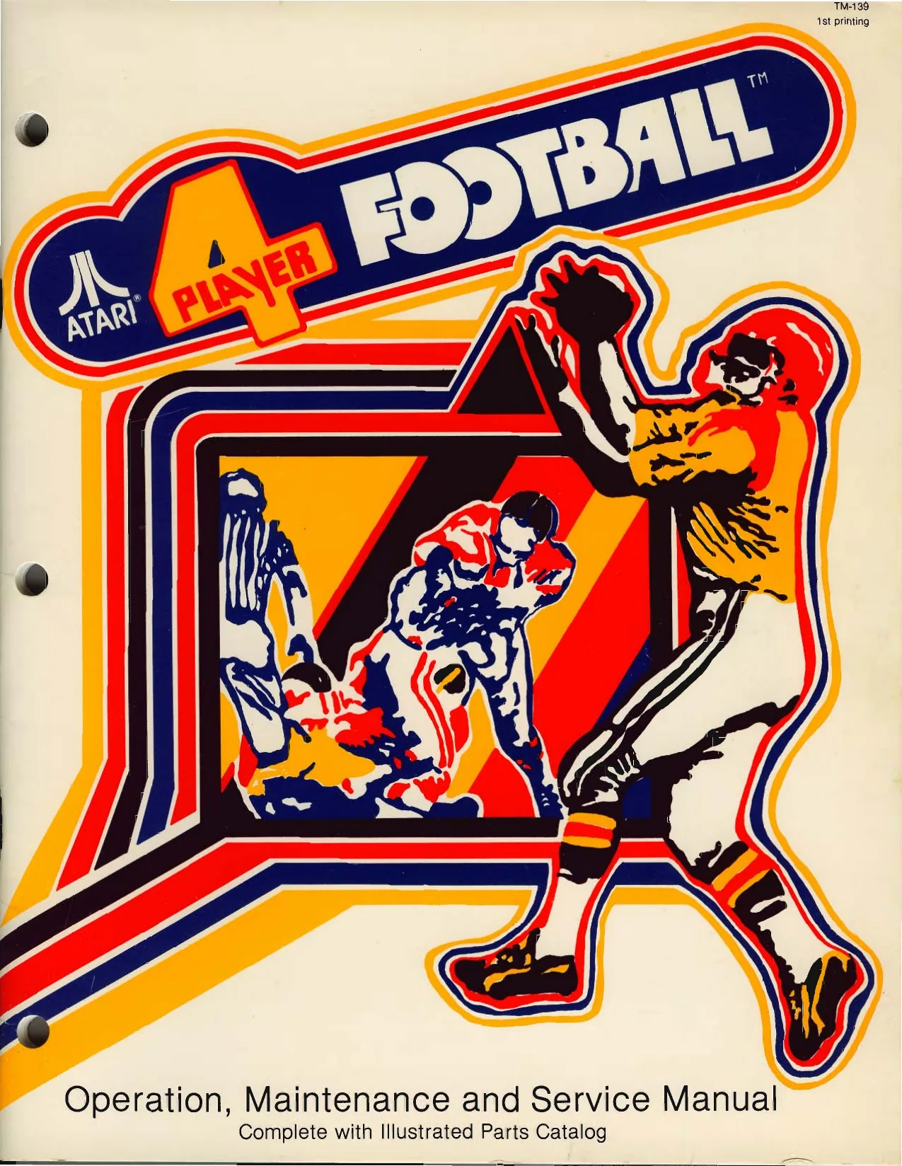
This page is a drawing, shown as the original scan.
GAME SERIAL NUMBER LOCATION
Your game’s serial number is stamped on the circuit (back) side, bottom right corner, of the printed circuit board—see the illustration below. The same number is also stamped on the label located on the rear of the game cabinet. Please mention this number whenever calling your distributor for service. tee
Operation, Maintenance and Service Manual
Complete with Illustrated Parts Catalog
ATARI, INC. 1265 BORREGAS AVENUE P.O. BOX 427 SUNNYVALE, CALIFORNIA 94086 408/745-2000 * TELEX 35-7488
A,
ATARI
Copyright © 1979 by Atari, Inc. All rights reserved
No part of this publication may be reproduced by mechanical, photographic, or electronic process, or in the form of a phonographic recording, nor may it be stored in a retrieval system, transmitted, or otherwise copied for public or private use, without permission from the publisher.
For permission requests, write:
ATARI INC. 1265 Borregas Avenue P.O. Box 427 Sunnyvale, California 94086
9H
Lithographed in the U.S.A.
ii 4-Player Football™
table of contents
location setup A. OVERVIEW OF GAME gh | DOHAG $ EE CB tee a eo eee oe B. GAMEINSPECTION ... 00.0000. 0 00 C. GAMEINSTALLATION.........
- Voltage Selection . . . : . : beens
- Interlock and Power On/Off Switches cee nite as owe ee vem es
- Game Fuses ................ pe higeas s LREeRE E yt ERE tase D. SELF- TEST PROCEDURE re
game play
INTRODUCTION. . ATTRACT MODE . PLAY SELECT MODE PLAY MODE.............00.20055 VOR>
maintenance and adjustments A. CLEANING........ B. FUSE REPLACEMENT ..... C. OPENING THE GAME TOP.
- Trak Ball Maintenance and Repair : : . eine
- Play Select PCB Repairs... 2-6-0 we. 18
- Pushbutton Switch Replacement ......0. 0000000 19
- TV Monitor Removal ......... es ae 7 ... 20 D. PRINTED CIRCUIT. BOARD REPLACEMENT be beee seer cad winerree 21
details of electronic operation
A. OVERVIEWOFGAME ..... : . 25 B. GAME WIRING AND POWER DISTRIBUTION. . 25 C. DESCRIPTION OF ELECTRONIC ASSEMBLIES ..... . tsp cemee 20
- Power Supply. - 0.0060 e eee ee 25
- Regulator/Audio PCB see beeen bee e eee e eee 25
- ControlPanel ............. bee e eee ee . 22. 25
- GamePCB . . . as re 25 @. Standard Syne: Watchdog and Power Reset 25 b. The Microcomputer 27 ¢. Video Generator 27 d, Input Circuits 27 e. Output Circuits 27
illustrated parts catalog
4-Player Football™ | iii
list of figures
Figure 1 Figure 2 Figure 3 Figure 4 Figure 5
Figure 6 Figure 7 Figure 8 Figure 9 Figure 10 Figure 11 Figure 12 Figure 13 Figure 14 Figure 15 Figure 16 Figure 17 Figure 18 Figure 19 Figure 20 Figure 21 Figure 22 Figure 23 Figure 24 Figure 25
iv 4-Player Football™ Overview of Game 2 Installation Requirements 3 Power Supply : bebe eee wae 4 Interlock and Power On/Off Switches .....0 0.00 e eee eee deve 5 Location of Self-Test Switch and Volume Control . 6 Option Switch Settings... ...... Self-Test Procedure ... . . Player Control Panel . Opening the Game Top . Trak Bail™ Control Repair Play Select Lamp and LED Replacement . . Pushbutton Switch Replacement . . . TV Monitor Removal ........... Game and Regulator/Audio PCB Replacement Power Distribution .. . bees . Signal Distribution . Final Assembly ......... Tabletop Hinges, Latches and Shield Control Panel Assembly Trak Ball™ Assembly Steering Board Assembly Play Select PCB Assembly . . see Regulator/Audio PCB Assembly. 00... 0.000 c ev eevee cece ec ee ees Power Supply Assembly for Raster-Scan Games. Coin Door Assembly Front Bezel Assembly 4-Player Football Game PCB Assembly . . .
This page carries no recoverable text. It is a drawing or a photograph. See the original scan.
If reading through this manual does not lead to solving a certain maintenance problem, call Tele-Help™ at the Atari Customer Service office in your geographical area, as shown in one of the two maps below. Order all parts from the California office.
WEST and CENTRAL U.S.A.
Parts for all Atari Customers. Sales and Service.
Atari Coin-Op Customer Service 1344 Bordeaux Drive, Sunnyvale, CA 94086 Telex 17-1103
(Monday - Friday, 7:30 - 4:00 pm Pacific Time) uo! = From California, Alaska or Hawaii (408) 745-2900
ee From anywhere else in this area yO) toll-free (800) 538-1611
EAST U.S.A. ‘Sales and Service Only
Atari Inc. New Jersey Customer Service Office 44 Colonia! Drive, Piscataway, NJ 08854 Telex 37-9347
(Monday - Friday, 8:30 - 5:00 pm Eastern time)
zs From New Jersey (201) 981-0490
@= From anywhere else in this area toll-free (800) 631-5374
vi 4-Player Football™
location setup
A. Overview of Game
The 4-Player Football™ game has two new Atari parts. If you have worked on Atari video games in the past, then you should be aware of these important differences. The new parts are described below and shown in Figure 1.
© Power Supply Assembly. It covers a wider voltage range than before, has higher reliability, a smaller overall size, and all fuse numbers and fuse amperages are marked directly on the metal chassis.
© Regulator/Audio PCB. Most of the heat-producing components have been moved off the game PCB and onto this smaller board, so the parts will not be prone to a higher rate of failure. Throughout this manual and illustrated parts catalog, wherever one of these two new parts is mentioned, you will see this symbo! in the page margin:
2/4 PLAYER BEZEL, SELECT SWITCH
a
COIN DOOR oN
COIN BOX
POWER CORD
Figure 1 Overview of Game PLAYFIELD (TV MONITOR SCREEN)
PLAY SELECT PANEL
TRAK BALL™ CONTROL
PLAY SELECT SWITCH
SPEAKER
POWER ON/OFF SWITCH
REGULATOR/AUDIO PCB
4-PLAYER FOOTBALL™M GAME PCB
“>
POWER SUPPLY
ACCESS PANEL
B. Game Inspection
This new game is ready to play upon removal from the shipping carton. However, your careful inspection is needed to supply the final touch of quality control. Please follow these steps to help us insure that your new game was delivered to you in good condition
- Examine the exterior of the game cabinet for dents, chips, or broken parts.
- Unlock and open the access panel of the cabinet and inspect the interior of the game as follows: a. Check that all plug-in connectors (on the game harness) are firmly seated. b. Remove the game printed circuit board (PCB) as follows:
- Remove the screws at the edge of the PCB closest to you. ¢ Unplug the edge connectors carefully. DO NOT BEND THE PCB.
- Slide the PCB out of its slots c. Verify that all integrated circuits (ICs) are firmly seated in their sockets or soldered in place. You should eliminate any foreign material such as loose bits of wire or solder splashes that could cause unwanted conductive paths. d . Note the location of the game’s serial number—it is on the metallic label in the upper left corner on the side of the cabinet. A serial number (not necessarily the same one) also appears in the corner of the back side of the game PCB. A drawing of this is on the inside front cover of this manual. Please mention this number whenever you call your distributor for service. e . Carefully slide the PCB back into its slot in the game cabinet and secure with the two screws at the board's edge closest to you. f. Plug the edge connectors back onto the PCB. DON'T FORCE THEM. The connectors are keyed so they will only go on in the proper orientation. A reversed edge connector will damage the PCB.
- Check all major subassemblies such as the power supply, loudspeaker (which contains powerful magnets that will attract small metal items—-remove these items), and all player-operated controls and switches. Check that the video monitor is securely mounted; tighten the hex nuts. below the monitor shelf as necessary.
C. Game Installation
Figure 2 Installation Requirements
110 VAC, 60 Hz (nominal), 120 watts OR 220 VAC, 50 Hz (nominal), 120 watts 0 to 38°C (32 to 100°F) Not over 95% relative 75 x 135 cm (29V2 x 53 in.) 94 cm (37 in.) Temperature Humidity Space Required Game Height
- Voliage Selection Before plugging in your game, make sure that the voltage selection plug on the power supply (see Figure 3) is correct for your location's line voltage. Check the wire color on the plug and <ee if it is correct per the list below
Line Voltage Range Voltage Selection Plug Color
90-110 VAC Violet 105-135 VAC Yellow 200-240 VAC Blue 220-260 VAC Brown a
POWER INPUT
Figure 3. Power Supply
- Interlock and Power On/Off Switches To minimize the hazard of electrical shock while you are working on the inside of the game cabinet, two interlock switches have been installed (see Figure 4). One is located behind the access panel and one is behind the coin door. These switches remove all the AC line power from the game circuitry when a door is opened.
Check for proper operation of the interlock switches by performing the following steps:
- Unlock and open the year access panel and the coin door.
- Plug the AC line power cord into an AC outlet.
- Set the on/off switch to its on position Close the rear access panel and coin door. Within approximately 30 seconds after closing the panel and door, the TV monitor should display a picture (the game lighting should light immediately).
- Slowly open the rear access panel. The TV monitor picture should disappear and the game lighting should go off when the panel is opened to approximately 2.5 cm (1 inch), Close and jock the rear access panel, and repeat this step with the coin door.
- If the results of step 5 are satisfactory. the interlock switches are operating properly. If the TV monitor and game lighting don’t go off as described, check to see if the corresponding interlock switch is broken from its mounting or stuck in the en position.
- Game Fuses Fuse locations and values are marked on the power supply chassis (see Figure 22). For continued protection of your game, as well as for the safety of the player, fuses must be replaced only with identically rated ones.
Information on the TV monitor fuses is printed in the TV monitor manual that has been supplied with your 4-Player Football game. »
POWER ON/OFF SWITCH
Figure 4 Interlock and Power On/Off Switches
D. Self-Test Procedure
This game will test itself and provide data to demonstrate that the game's circuitry and controls are operating properly. The data is provided on the TV monitor and the game speakers: no additional equipment is required.
Part of the self-test includes a test of the volume level and a display of the operator-selected game options. Therefore, we suggest you run the self-test anytime you need to adjust the volume or change the options. Besides, this method will eliminate an inaccurate coin count, which would be gotten by tripping the coin switch wire merely to change the volume level during game play
To begin the self-test, follow the instructions outliried in Figure 5
VOLUME CONTROL
A VOLUME INCREASE: TURN CLOCKWISE MO
OFF SELF-TEST. SWITCH
Location of Self-Test Switch and Volume Control
Option Switch Settings
To change the toggle positions of the switch assembly, you need not remove the PCB. The switch, usually colored blue, is easily accessible when the PCB is left mounted in place
Switch Setting on 4-Toggle DIP Switch (on game PCB)
| 4 | 3 | 2 | 1 | Result | Display During Self-Test |
| Off | 70 seconds per coin | F | |||
| On | 90 seconds per coin | $ | N | ||
| On | 1-coin minimum | N | |||
| Off | 2-coin minimum | ft | $ | F |
Right coin mechanism (as you face the game) registers:
| On | On | 1 unit of time per coin | N | N | |
| Of | On | 4 units of time per coin | N | F | |
| On | Off | 5 units of time per coin | 3] | F | N |
| Off | Off | 6 units of time per coin | F | F |
{Left coin mechanism always registers 1 unit of time per coin)
Xs represent switch numbers 4,3,2,1 on the 4-toggle DIP switch, namely N = on, F = off.
$ Indicates settings made at the factory and/or recommended settings. + Game time is shown after one coin, but the controls are inactive until the second coin is inserted.
Instruction Self-Test Procedure
Result if Test Passes Result if Test Fails
- RAM AND ROM TEST
Set self-test slide switch to the on position (tocated below the volume potentiometer, immediately behind and to the left of the coin door).
- SCROLLING PLAYFIELD TEST
Press the Play Select pushbutton on either control panel. Release the Play Select pushbutton
- TRAK BALL TEST
Roll any Trak Ball in random motion and observe TV monitor.
Press and hold down either Play Select button; then roll ail 4 Trak Ball controls In sequence
- AUDIO, SWITCH AND LAMP TEST
Press all the following switches: slam. the coin switches. play select and 2/4 players switches, TV monitor dispiays ROM OK RAM OK as shown below:
sec cnee Cate BEDaaSDHIF MWNOS Manis 2 Pu. n
vepes-ongrorpacSHEEE Rute
§ scrolling Directions 4
Playfield scrolls towards the pressed button.
Piayfield will freeze.
An L-shaped arrow pointing towards that Trak Ball will move around the entire playfield exactly as you move the control.
Each switch activation (closed or open) enables a different set of arrows to move for all 4 Trak Balls. A press/release/ press/release series will cycle thru all 4 arrows of each Trak Bail
Background crowd sound increases in volume, the more switches you hold down simultaneously.
Each pressed switch generates 2 beeps
- one beep when pressed and a second beep when released All incandescent lamps are lit (LEDs remain dark} BAD RAM and/or BAD ROM will be displayed on the monitor
No playfield scrolling motion
The appropriate arrow does not move in the sare direction as the Trak Ball.
No crowd sound: indicates bad sound circuitry, loose speaker wires, bad switch circuitry, or volume contol turned ali the way down.
Crowd sound does not increase or no beep sound: indicates a bad switch.
Either some or all lamps are dark (burned out)
Instruction Self-Test Procedure
Result if Test Passes
- OPTION SWITCH DISPLAY
Observe the open dark-gray playfield area on the screen, near the ROM OK ot BAD ROM message. A combination of Ns and Fs is displayed under the ROM message. This indicates how the option switches have been set on the game PCB. See the Option Switch Settings list on page 7 for how to set your 4-Player Football game to its various options. Result if Test Fails
N or F does not match actual DIP switch setting. Indicates a game circuitry malfunction.
4-Plaver Football™ 9
This page carries no recoverable text. It is a drawing or a photograph. See the original scan.
game play
A. Introduction
The Atari 4-Player Football™ game has three different modes of normal operation. These modes are described below: Attract — when power is applied or as a result of a game ending with no further credits. Select Play — before each scrimmage. Play — begins after the hike
The 4-Player Football game consists of two player control panels (illustrated in Figure 6). These two control panels are operated independently by opponents. Each control panel is capable of operating either the offense or defense, depending on the point in time during the game.
Each control panel consists of two Trak Ball controls, a Play Select PCB and its acrylic graphics panel, and a triplefunction LED pushbutton. The LED's primary function is to select one of the various plays, and its other functions allow passing or kicking. When the Play Select switch is active, the LED flashes. Once the ball is hiked, the LED will go dark, changing the switch function to passing or kicking (offense only).
The play select panel illustrates five offensive and five defensive plays. The panel is backlighted by six incandescent lamps. Prior to selecting any of the five plays. the five LED lamps are dark.
Pressing the Play Select pushbutton lights a random LED. The player may now make a selection by “stepping” the LED from left to right, before the scrimmage begins. On the next play. the LEDs stay dark until the pushbutton is pressed again
The Trak Ball is the control for the wide receiver or quarterback if you're the offensive player, or for the defensive backs. This control is operated by rolling it in any direction with the palm of your hand. It moves the appropriate man to any position on the scrolling playfield by moving him at a rate proportional to the roll of the ball. The Trak Ball and the Play Select pushbuttons will only be enabled during the play select and the play modes. Otherwise, these controls are disabled.
B. Attract Mode
The attract mode begins when AC power is applied to the game and the power on/off switch is turned on. While in the attract mode, the TV monitor randomly displays the plays, and the game simultaneously lights up the corresponding LED. The Xs indicate defensive players, and the Os indicate offensive players. This mode alternates randomly between 2- and 4-player games; it also demonstrates use of the 2/4 player pushbutton by lighting and turning it off, as appropriate
C. Play Select Mode
The play select mode begins immediately after the necessary coins are accepted by the coin mechanism. After this, the Play Select pushbutton switch becomes active. The screen then changes from the attract mode display to the huddle. The game is now in the players’ hands, and the crowd audio is tumed on.
Actually this mode exists at each huddle, regardless of the score or of offense or defense conditions. The coin message is no longer displayed in the scoreboard display area. Instead, the scoreboard indicates whether you are the offense or defense for the current scrimmage; it also shows a zero
12 4-Player Footbali™ score when first placed into the play select rnode. The down number and yards to go are displayed. and time begins counting down. The Play Select LED flashes, and the switch becomes enabled
During the play select mode the player may select either the 2- or 4-player option. The LED pushbutton on top of the game above the coin door is identified with the corresponding 2/4 player status. During 2-player games, only the two right Trak Balls are enabled {as seen when facing each control panel}. The 2/4 Player pushbutton is only enabled during the time between scrimmages—when play selections are made
During the play select mode, the players may select a certain play by pressing the Play Select pushbuttons. Immediately after doing so, that team's players are set to the line of scrimmage.
The game circuitry accepts coins at any time. Each coin adds time to the game timer (either 70 or 90 seconds— selected by the operator). However, if the operator sets the game for the 2-coin minimum, one of those coins buys the player into the game (game time is displayed); the controls are inactive until the second coin is inserted. In either 1- ot 2-coin minimum situations, if coins are added during a game, the time is extended with no other effect. If coins are added in the attract mode, the scores are reset to zero, and the game enters the play select mode.
D. Play Mode
Seven players are on each side or tearn, indicated by the seven Xs for defense and seven Os for offense. Two or four players control the flashing Xs and Os with their Trak Balls; the balance is controlled by the game’s computer.
Refer to Figure 6 for details on the ten different plays and game instructions. The play select panel shows exactly how all the defensive and offensive piayers maneuver. Where the panel actually shows yellow players that you control, we have printed those players in light grey in the figure
PLAYER GAME Runt RAR HALES CTR INSERT COIS awsm Co FEMME Sos cOstho ais ER INSTRUCTIONS S SELECT 2 Of § PLAYERS rcs un ANON CO Oe # ERASER GAML i > ZOR 4 CAN PLAY PP Si cicrpuay micsrim siutcr gus iONtNTE bepuieteay S41) geantiansen ots
+ TO PASS pwEsd PLAY SELICT aUTIONS PASSES ALLOWED BEHIND LIMt OF SCRIMMAGE ON SLANT HLAY'S PMESS PLAY SELECT HUTTON (COMPUTER CONTROLS DIRECTION PUNT FORKARD SPELD OF TRAKBALL AT START OF KICK DETERMINES QISTANCE OF HICK FIELD GOAL FIELD GOAL ATTEMP" ALLOWED INSIDE 30 YARD LINL AFTER SCORING Ba
OFFENSIVE PLAYS Leal é pee
SLANT OUT SLANT IN 20MB__DOWN AND OUT _KICK Oo 0° paca 05429
DEFENSIVE PLAYS
Figure 6 Player Control Panel
4-Plaver Foothall™ 13
This page carries no recoverable text. It is a drawing or a photograph. See the original scan.
and
adjustments
A. Cleaning
The exterior of the game cabinet and the glass and acrylic panels may be cleaned with any non-abrasive household cleaner. If desired, speciai coin machine cleaners that leave no residue can be obtained from your distributor. Do not dry-wipe the small acrylic play select panel, because any dust can scratch the surface and result in fogging the plastic. (The large monitor shield is made of tempered glass and should be scratch resistant.)
On
B. Fuse Replacement
This game contains six fuses ~ all on the power supply assembly (not including the TV monitor fuses). Replace fuses only with the same type as listed below. See the TV monitor manual for the monitor fuse data. F1, F2, F3 7-amp. 250V 3AG slow-blow glass cartridge-type fuse
F4, F5, F6 3-amp. 250V 3AG slow-blow glass cartridge-type fuse
The metal power supply chassis is marked with all six fuse numbers and amperages. Figure 22 shows the power supply in detail, including top and botem views.
C. Opening the Game Top
Prior to repairing or replacing any component on the game top or prior to removing the TV monitor, unplug the game. Then open the coin door.
Reach through the opening and unlock both luggagestyle latches above the coin door (see Figure 7). Lift up the game top and tilt it away from you. The two gas springs will hold the top up. Do not jam the game top up against its topmost position — this is hard on the gas spring mounting hardware.
LUGGAGE-STYLE LATCH
Figure 7 Opening the Game Top
- Trak Ball™ Maintenance and Repair
To maintain this control. you will only have to lubricate the bearings approximately every $1,000 in income earned or every 2,000 credits. The number of credits can be read off the coin counter. located on the coin door. Use only 2 drops of 3-in-One® oil in each of the ball bearings. (Each Trak Bali control has five bearings.)
For further instructions on how to replace the Trak Ball or either steering PCB, see Figure 8.
Trak Ball™ Control Removal
- Open game top as illustrated in Figure 7.
- Remove eight Allen-head screws from the control panel. See () in this figure. © Lift out entire contro! panel as shown by direction of arrow. + Remove three carriage bolts trom Trak Ball assembly. See @, Remove the Trak Ball assembly. Ball Replacement Remove three countersunk machine screws from the Trak Ball assembly's acrylic top plate. (When the assembly is installed, these three screws are right underneath the control panel.) See). Remove and replace the ball. See (2).
Steering PCB Unplug connector on steering PCB. Remove two crossrecessed machine screws, associated washers and hex nuts from the steering PCB. See(). Remove the steering PcCB. See (). When replacing this PCB assembly, be certain that the black toothed wheel turns freely between the two halves of the red photo sensor device.
Figure 8 Trak Ball™ Control Repair
A A
- Play Select PCB Repairs
Two problems could occur with this PCB. A light-emitting diode could burn out. or one of the six incandescent lamps could burn out. To replace any LED or lamp, open the game top and remove this small PCB as described in Figure 9.
- Open the game top as illustrated in Figure 7.
- Unplug the white connector on the Play Select PCB.
- Remove the two flat washers, split lock washers, and hex nuts that hold down the Play Salect PCB. Remove this board.
- Replace the small burned-out tamp or light-ernitting diode, as needed.
Figure9 Play Select Lamp and LED Replacement
- Pushbutton Switch Replacement
The three light-emitting diode (LED) switches on top of the game have a very low failure rate. In case a switch should ever be suspect, first test it per the description that follows. To replace the switch, refer to Figure 10.
@ Remove the wires from the suspected switch
@ Set multimeter to ohms scale. Set ohms scale to R Connect multimeter ieads to appropriate LED switch contacts. (See Figure 10 for designation of switch contacts and meter lead placement.)
Check contacts (push and release the switch button) for closed and open continuity.
If the contacts do not operate sharply or always rex 1, then zero the meter main closed or open, then replace the LED switch as described in Figure 10.
COMMON T-EMITTING CONTACT ee ji DIODE (L.E.D) CONTACTS
"NORMALLY OPEN \ (N.0.) CONTACT ‘\ NORMALLY CLOSED (N.C.) CONTACT
L.E.D SWITCH: TO REMOVE TURN COUNTERCLOCKWISE LED SWITCH TESTING
© Remove all wires trom the taulty switch. © Turn the switch counterclockwise while holding the black cone-shaped molding on the outside of the control panel.
- Install a new switch using the reverse procedure. © Reconnect the harness wires.
SINGLE-POLE DOUBLE-THROW (SPDT) SWITCH WITH INTERNAL LED
Figure 10 Pushbutton Switch Replacement
- TV Monitor Removal
ff you should need to service or replace the 23-inch TV monitor, you must first remove it from the game cabinet. To avoid possible back strains you should have a helper assist you in this procedure. Follow the instructions in Figure 11
High voltages exist in any television unit, even with power disconnected. Use extreme caution and do not touch electrical parts or the TV yoke area with your hands or with metal objects in your hands!
- Open the game top as described in Figure 7. Be sure the game is unpluged.
- Unplug the TV monitor hamness connector.
- Remove the eight TV monitor wood screws and tie-down. brackets. Then remove the two carriage bolis and wing nuts on the TV's metal chassis.
- With the help of another person, if possible, lift the monitor assembly up and out of the game.
Figure 11 TV Monitor Removal
D Printed Circuit Board the edge connectors (on game board) or the three small Replacement 4. Carefully slide the PCB straight out of its slots. Be
harness connectors (on Regulator/Audio board).
careful not to twist the board, as this may loosen connections or components. Replace or repair as required.
You may wish to remove the game printed circuit board 5 (PCB) or the Regulator/Audio PCB for service or inspection. To do this, refer to Figure 12 and proceed as foliows: . Reinstall sxe PCB, making sure that the connectors are properly plugged in. Note they are keyed to fit on only one way, so if they don’t slip on easily, don’t force them! A reversed connector can damage the machine.
- Open the side access panel. Be sure the game’s power is off. 7. Replace the securing screws and fiber washers in the PCB. Reinstall the black connector mounts on the P.C.
- Locate the securing screws and fiber washers that hold board. Close and lock the side access panel. down the PCB in its slots, and remove them {two screws and washers for each PCB). 8. Check that the operation of the game is correct and perform the self-test. This is especially important with any 3.. If you are removing the game board, first remove the game when you replace a PCB. Normally the only adfour machine screws that hold the small black connec- justments on the game PCB are option switch changes tor mounts along the game PCB's edge. Then unplug (made on the 4-toggle DIP switch).
REGULATOR) AUDIO PCB
4-PLAYER FOOTBALL GAME PCB
OPERATOR OPTION SWITCH
GAME PCB
Figure 12 Game & Regulator/Audio PCB Replacement
4-Plaver Fanthall™ 91
This page carries no recoverable text. It is a drawing or a photograph. See the original scan.
details of electronic operation
With this manual you received two large sheets that contain the wiring and schematic diagrams for the 4-Player Football™ game. Sheet 1, Side A, includes an index that shows the arrangement of these diagrams. These diagrams include information that explains the functions of the circuits and defines inputs and outputs. We hope these larger schematics solve the problems some technicians were having with the smaller diagrams in our previous manuals. By putting them on large sheets, we were able to make them much easier to read, as well as maintaining smoother continuity from one circuit function to another.
PLAY SELECT PCB
PLAY SELECT PCB ZS a =
TV MONITOR Tl
REGULATORIAUDIO PCB
COIN DOOR me nt 5 °
3 GAME INTERLOCK oor [US GAME PCB NN Le 10.3 voc 6.3 VAC
POWER SUPPLY
Figure 13. Power Distribution
A. Overview of Game
Electrically and electronically 4-Player Football operates the same as the 2-player Football, except for the following differences:
- Two additional Trak Ball controls.
- Additional connector on the game PCB.
- Power regulator removed from the game PCB.
- Audio amplifier removed from the game PCB.
- Addition of various test points on the game PCB. 6} Addition of the 2 PLAYER/4 PLAYER pushbutton
- Addition of the Regulator/Audio PCB. 8} Newly designed Power Supply
As in the 2-player game, 4-Player Football contains a raster-type monitor. The raster monitor generates the horizontal and vertical raster scanning signals internally. The game PCB contains a standard sync circuit that synchronizes the game PCB with the scanning of the monitor raster. The composite video output of the game PCB contains the following signals: 1) vertical sync; 2) horizontal sync: and 3) Z axis output for intensity modulation of the monitor raster bearn.
Pat
B. Game Wiring and Power
2 gee .
Distribution
The wiring diagrarn for the 4-Player Football game is located on Sheet 1, Side A, of the large sheets that came with this manual. Included on this sheet are the schematic diagrams for the power supply, Regulator/Audio PCB, coin door, and contro} panel.
Figure 13 of this manual shows the distribution of the power of this game.
C. Description of Electronic
Assemblies
The following sections describe the electronic assemblies within the 4-Player Football game. For information on the monitor, refer to the monitor manual.
Figure 14 of this manual shows the distribution of signais of this game
- Power Supply The power supply is located on the floor of the game cabinet. This supply was specifically designed to provide the voltages required for both raster and X-Y games. Some of the features of this new supply include: a new transformer with greater power output and additional secondary windings; one unregulated DC voltage output. and various AC voltage outputs: a line-filtered AC line input; appropriate voltage selection plugs for different ranges of AC line voltages; and a bank of fuses located on an easily accessible fuse block. with fuse values plainly labeled beside each fuse
- Regulator/Audio PCB The Regulator/Audio PCB is the smaller PCB mounted ‘on the inside wall of the game. It was designed for two reasons: 1} to remove high-heat-producing components from the game PCB, and 2) to provide better regulation of the +5 VDC logic power for the game PCB. A description of both the regulator and audio sections of this PCB is included on Sheet 1, Side A, of the large sheets included with this manual.
- Control Panel
The two control panels at each end of the game are identical, and each contains two Trak Balls and one 4-Player Football Play Select PCB. The wiring diagram for the control panels is on Sheet 1, Side A, of the large sheets. Schematic diagrams for the LED circuits of the Play Select PCB and Trak Ball Steering PCB are located on Sheet 1, Side B, of the large sheets.
As shown on the wiring diagram, the six #47 lamps contained on each Play Select PCB are connected in parallel. However, the lamp circuits of the two PCBs are wired in series and connected to 6.3 VAC
- Game PCB The game PCB is the larger PCB mounted on the inside wall of the game. This PCB contains a standard sync circuit, microcomputer (see Sheet 1, Side B), video generator (see Sheet 2, Side A), player control inputs and option switch circuitry, and control panel and audio outputs (see Sheet 2, Side B).
a. Standard Sync; Watchdog and Power Reset The standard Sync Circuit and the Watchdog and Power Reset circuits are the only circuits on the game PCB thai are not controlled by the microprocessor. The syne circuit provides the 0 clock input (4H @ 750 KHz) to the microprocessor and synchronizes the video generator with the scanning of the monitor's raster. The Watchdog and Power Reset circuit causes the microprocessor to start its instruction sequence from the beginning of the program after power-up or after a program error
4-Plaver Foothall™ 95
PLAYER 1 PLAY SELECT PCB
GAME SPEAKER TV MONITOR (1 of 2)
REGULATOR/AUDIO COIN DOOR PCB
| | — Game pce
TEAM 2 TRAKBALL INPUTS
SELECT2 LEO CO- LED CS
SELECT
TEAM 1 TRAKBALL INPUTS
Figure 14 Signal Distribution
b. The Microcomputer The microcomputer consists of the microprocessor. address decoder, and memory. The microprocessor (MPU) is the “master controller” of all action that takes place in the game circuitry. Upon initialization, the MPU (via ABUSO thru ABUS14) addresses data locations in the program ROMs or PROMs. The data from the addressed locations then travels to the MPU via the 8-bit data bus (DO thru D7). The MPU decodes this data to determine whai action it should perform next (i.2., “read coin switch 1”, “PASS”, etc.). The MPU uses RAM memory to temporarily store information which it will later recall. The MPU is capable of writing (or putting data into) the RAM and then later reading {pulling data out of the RAM) via the address bus and bidirectional data bus.
The address decoder performs the critical function of turning on or enabling the appropriate game circuitry (i.e., RAM, ROM, latches, etc.) ai the correct times, so that information can be transferred back and forth between the game circuitry and the MPU. An address map for the address decoder is included on the schematic diagram on Sheet 1, Side B.
c. Video Generator The video generator produces all the video seen on the monitor. It produces three signals: 1) the playfield; 2) the moving objects (Xs, Os, football, and scrimmage line marker); and 3) all alphanumerics at each end of the playfield. When you play 4-Player Football, your view of the monitor is from the side. However, the following information is in reference to the monitor sitting in its normal orientation with the longer sides of the screen at the top and bottom. The schematic diagram for this circuit is on Sheet 2, Side A, of the large sheets included with this manual.
The monitor display for this game has a raster of 240 horizontal lines. These lines are separated into three sections. The message section on each side of the screen that displays game-related messages is generated by the alphanumerics generator. The video for the playfield and moving objects in the center section are generated by the graphics generator. Both the alphanumerics and graphics generators produce picture elements called “stamps”, that are eight horizontal bits wide by eight vertical lines high. The playfield is 24 stamps wide by 30 stamps high. Each message section is 3 stamps wide by 30 stamps high
The alphanumerics generator receives data from the microcomputer that addresses the alphanumerics PROM. However, the PROM can only output data to the video summer during a window period that occurs at the beginning and end of the horizontal! scan period. The data frorn the PROM may be outputted forwards or backwards from the circuit, so that the messages may be read from either end of the game.
The playfield and motion object pictures are developed through a process called “direct memory access” (abbreviated DMA) or “cycle sharing”. This is done by the microcomputer directly accessing the video generator’s RAM. The microcomputer addresses the RAM and writes daia into it that designates which stamp is to be displayed Then the microcomputer’s address lines are removed, and sync addresses the RAM. Since sync represents the location of the monitor beam, the RAM outputs data that defines the picture stamps at the desired locations. The graphics PROM receives the data output from the RAM as an address input, and outputs eight picture elements for each line of each stamp.
d. Input Circuits The schematic diagram for the input circuits is located on Sheet 2, Side B, of the large sheets.
The input circuits receive daia from all the game switches, the option switches and Trak Balls. The game switch and option switch inputs are all connected to pullups. Each switch input pulls its related signal input to ground when the switch is closed. Each Trak Ball has two steering PCBs that produce pulses to define in what direction and how fast the Trak Ball is turning. These pulses are processed by the input circuitry to develop binary signals that represent the direction and speed of the Trak Ball. This information is read by the microcomputer on its data line input.
e. Output Circuits The schematic diagram for the output circuits is on Sheet 2, Side B, of the large sheets.
The output circuits generate the audio, trip the coin counters on the coin doors, and light the LEDs of the game. The audio is produced when the microcomputer addresses the audio circuit (i.e. the address decoder outputs OUT1 or OUT2) and writes data to the audio data latches. The data creates the audio from either a random noise generator or a 555 timer. The audio is then sent to the audio section of the Regulator/Audio PCB for controllable volume amplification. The AMP ON signal, when low, enables the audio amplifier.
The coin counter output circuit accommodates up to three counters. The counters are tripped when the coin counter drivers receive high data signals from the microcomputer.
The anodes of all the game LEDs are connected to drivers that are controlled by vertical sync. The cathodes are connected to drivers that are controlled by data signals from the microcomputer. The resulting matrix of LEDs is lighted or turned off at the command of the microcomputer.
This page carries no recoverable text. It is a drawing or a photograph. See the original scan.
illustrated parts catalog
The purpose of this chapter is to provide you with the necessary information for ordering replacement parts for the 4-Player Football™ game. Please note that, for simplicity, all common hardware has been deleted from these parts lists (except for Figure 18, Trak Ball Assembly). This includes screws, riuts, washers, bolts, etc.
When ordering parts from your distributor, give the part number, part name, applicable figure number of this catalog, and serial number of your game. This will help to avoid confusion and mistakes in your order. We hope the results will be less downtime and more profit from your game.
Figure 15 Final Assembly A034816-XX B @)4-FLLS BRE (BQ)Z-/UCS ~ 4Lcs @) ~
B ones G. N\ NS
- AACS
wecrion AN. alk. REC/AvoIO
- Bee secr>| [| g <<
Game 60
i
Figure 15 Final Assembly Parts List
| Item | Part No. | Qty. | Description |
| 2 | A034821 | 2 | Control Panel Assembly — see Figure 17 |
| 3 | A034485-01 | 1 | Regulator /Audio PCB Assembly — see Figure 21 |
| 4 | A034754-01* | 1 | 4-Player Football PCB Assembly (PROM version) — see Figure 24 |
| 5 | A034560-01 | 1 | Power Supply Assembly for Raster-Scan Games — see Figure 22 |
| 6 | A034841-03 | 1 | Power Cord Assembly (domestic) |
| 7 | A034974-01 | 4 | Gas Spring Mounting Assembly |
| 8 | A034980-01 | 1 | Main Harness and Component Assembly |
| 9 | A034820-01 | 1 | Access Door Assembly |
| 10 | A021084-01 | 1 | Voltage Selection Plug (100V) |
| 1 | A030268-01 | 1 | Coin Box Assembly |
| 12 | A035319-01 | 1 | Coin Door Adapter Harness Assembly |
| 14 | 000869-01 | 2 | Speaker Grille |
| 15 | 034537-01 | 1 | Mesh Ventilation Grille |
| 16 | 006870-01 | 1 | Coin Box Bracket |
| 17 | 007882-02 | 2 | Interlock Switch Cover |
| 18 | 009992-01 | 1 | On/Off Switch Cover |
| 19 | 034973-01 | 1 | Cardboard Bezel with Graphics |
| 20 | 034971-01 | 1 | 23" Monitor (modified) |
| 21 | 005594-01 | 4 | Monitor Tie-Down Bracket |
| 24 | 033127-01 | 1 | Black Molded Switch Bushing |
| 25 | 030868-01 | 4 | Connector Mount |
| 26 | 034536-01 | 1 | Foam Vibration Damper |
| 27 | TM-139 | 1 | 4-Player Football Technical Manual with Illustrated Parts Catalog |
| 28 | DP-139-01 | 1 | Schematic Drawing Package, Sheet 1 |
| 29 | DP-139-02 | 1 | Schematic Drawing Package, Sheet 2 |
| 36 | 48-004 | 2 | 5" 8-ohm Speaker |
| 42 | 75-990805S, | 4 | #14-20 Shallow-Pattern Prevailing-Torque Steel Lock Nut |
| 47 | 73-3029 | 4 | Special Retaining Clip for Gas Spring |
| 48 | 78-3116 | 2 | Gas Spring |
| 49 | 62-039 | 1 | Pushbutton LED Switch |
| 51 | 7507017 | 4 | Fiber Washer with 5/32" Inside Diameter 3/8" O.D. x 1/8" Thick |
| 53 | A009083-XX | 1 | Coin Door Assembly ~ see Figure 23 |
| 55 | 035118-01 | 3 | Warning Label for Interlock and Power On/Off Switch Covers |
| 56 | A021084-02 | 1 | Voltage Selection Plug (120 V) |
| 57 | A021084-04 | 1 | Voltage Selection Plug (220 V) |
| 58 | A021084-05 | 1 | Voltage Selection Plug (240 V) |
- A034754-02 is an acceptable substitute (ROM version) — see Figure 24
ATARI
4-Plaver Fanthali™ 24
SECTION
CONFIDENTIAL Reproduction for
fim or manten permission #om the earporaton NO'CE 10 ALL PERSONS RECEWING THIS DRAWING a
| ci | ¥ | Sunes | |
| Gi | " | f | x |
= a : A-A
LA
Figure 16 Tabletop Hinges, Latches and Shield A034817-01 A Parts List
| Item | Part No. | Qty. | Description |
| 3 | 034383-01 | 2 | Hinge |
| 4 | 034388-01 | 2 | Latch Keeper Bracket |
| 5 | 034387-01 | 1 | Tempered Glass Monitor Shield |
| 6 | 034970-01 | 4 | Shield-Mounting Cleat |
| 12 | 78-3408 | 2 | Spring Draw Latch (Hook End) |
| 13 | 78-13003 | A/R | R.T.V. Glue, General Electric Part No. 108 |
- 4-Player Football™
ic PLES
QUERLAE Tare \ 4S SHOWN) W/Bat AES W/BK Fa be — — wy (Com) -- y, W.0.)
Figure 17 Control Panel Assembly A034821-01 A Parts List
| Item | Part No. | Qty. | Description |
| 1 | A033360-01 | 2 | Trak Ball Assembly — see Figure 18 |
| 2 | A034981-01 | 1 | Control Harness Assembly |
| 3 | A034872-01 | 1 | Play Select PCB Assembly — see Figure 20 |
| 4 | 034385-01 | 1 | Acrylic Play Select Panel |
| 5 | 033097-01 | 1 | Wood Suppon for Play Select PCB |
| 6 | 033127-01 | 1 | Black Molded Switch Bushing |
| 7 | 034384-01 | 1 | Meta! Control Panel |
| 10 | 62-039 | 1 | Pushbutton LED Switch |
| 17 | 70-11-47 | 6 | NEMA #47 Incandescent Miniature Bayonet-Base Lamp |
ADiavor EnnthalllM 22
Figure 18 Trak Ball™ Assembly A033360-01 G
34 © 4-Player Football™
Figure 18 Trak Ball™ Assembly Parts List
| Item | Part No. | Qty. | Description |
| 1 | 033355-01 | 1 | Base Plate |
| 2 | 033356-01 | 1 | Top Plate |
| 3 | 033357-01 | 1 | Cover Plate (Acrylic) |
| 4 | 033358-01 | 1 | Corner Post |
| 5 | 033359-01 | 2 | End Post |
| 6 | 033361-01 | 2 | Steering PCB Bracket |
| 7 | 033362-01 | 2. | Roller Shaft |
| 8 | 033363-01 | 1 | Cylindrical Post |
| 9 | 033364-01 | 1 | Adjustable Post |
| 10 | 033365-01 | 1 | Spacer |
| i | 000616-01 | 2 | Light Hub |
| 12 | 033366-01 | 1 | Trak Ball™ |
| 13 | 74-A00011 | 4 | Phenolic Spacer, 1/8” inside diameter x 1/4" outside diameter x Ya" long |
| 14 | A009060-02 | 2 | Steering Printed Circuit Board Assembly — see Figure 19 |
| 15 | 033367-01 | 5 | Bearing |
| 16 | 73-3006 | 2 | Carbon Spring Stee] External Retaining Ring, for 3/8” shaft diameter |
| 7 | 72-8808 | ) | #8-32 x "2" Hex Socket-Head Cap Alloy Steel Machine Screw |
| 18 | 72-1006S | 2 | #10-32 x 3/8" Cross-Recessed Pan-head Cadmium-Plated Steel |
Machine Screw
| 19 | 72-1606S | 4 | #6-32 x 3/8" Cross-Recessed Pan-Head Cadmium-Plated Steel |
Machine Screw
| 20 | 72-1408S | 4 | #4-40 x 1%" Cross-Recessed Pan-Head Cadmium-Plated Steel |
Machine Screw
| 21 | 72-8920 | 1 | #3/8-16 x 1%" Hex Socket-Head Cap Alloy Steel Machine Screw |
| 22 | 85-1808B | 4 | #8-32 x '%" Socket Cap Flat Countersunk-Head Black-Oxide Stee] Screw |
| 23 | 75-3608S | 3 | 46-32 x '/2" Cross-Recessed Flat-Head Cadmium-Plated Steel |
Machine Screw
| 26 | 75-046S | 7 | #6 Zinc-Plated Steel Split Lock Washer |
| 27 | 75-0488 | 9 | #8 Zinc-Plated Steel Split Lock Washer |
| 28 | 75-040S | 2 | #10 Zinc-Plated Steel Split Lock Washer |
| 29 | 75-041S | 1 | #3/8 Zinc-Plated Steel Split Lock Washer |
| 31 | 75-010S | 2 | #10 Flat Plain SAE-Standaid Zinc-Plated Steel Washer |
| 32 | 75-0188 | 2 | #8 Flat SAE-Standard Zinc-Plated Steel Washer |
| 33 | 75-016S | 3 | #6 Flat Plain SAE-Standard Zinc-Plated Steel Washer |
| 35 | 75-990504C | 4 | #4-40 Shallow-Pattern Prevailing-Torque Corrosion-Resistant |
Steel Lock Nut
| 36 | 75-916S | 3 | #6-32 Standard Cadmium-Plated Steel Machine Hex Nut |
| 37 | 75-9198 | 1 | #3/8-16 Standard Cadmium-Plated Steel Machine Hex Nut |
| 38 | 034168-01 | i | Label with Lubrication Instructions |
A ATARI
A_Plavor Fanthalll™M 25
NOTICE 30 ALL PERSONS RECEIVING THIS DRAWING CONFIDENTIAL ‘Reproduction terbuaces wihout the specilic. writen permesian of Atari. Inc. Sunnyvale Caniorma Ths wawing 1 Only condwionally 1s5ued, she
iywenten agreement ‘wun or watten permission Hom the couporalion pts ed yoos°eReo
Je TRACES SHOWN ARE ON OPPOSITE WOE
Figure 19 Steering Board Assembly A009060-02 C
Parts List ev IFATA® °
RB EMING BD
| Item | Part No. | Qty. |
Description Ref. Designation
| 5 | 10-5392 | 2 |
| 6 | 10-5331 | 4 |
| 7 | 10-5471 | 2 |
| 8 | 27-250104 | 1 |
| 9 | 29-046 | 1 |
| 10 | 34-2N3643. | 2 |
1379-58005 1
| 14 | —-030369-01 | 1 |
3.9K ohm, +5%, /4W Carbon Composition Resistor 330 ohm, +5%, %4W Carbon Composition Resistor 470 ohm, +5%, %4W Carbon Composition Resistor O.1 wf, + 20%, 25V Ceramic-Disk Radial-Lead Capacitor 10 uf, +10%, 20V Tantalum Axial-Lead Capacitor Type 2N3643 NPN Switching Transistor 10-Contact Connector Radial Optical Coupler R14, 15 R10-13 R7,8 C2 cl Ql, 2
ATARI"
NOTICE TO ALL PEAS CONFIDENTIAL Spo en
On YAIJS2I0 JIANTOOW A3YAIG=b @8'O IAATA b SXBbe0R -@® [A] __ to-cieneo Le
yi OY
z off ists
| wvgoss | acta | gycea | ta ces |
iz > tt ii ea]
Figure 20 Play Select PCB Assembly A034872-01 A
Parts List
| Item | Part No. | Qty. | Description | |
| 2 | 38-MV5053 | 5 | Light-Emitting Diode with Red Diffused Cap: | 1.6 mcd, 20 mA, |
17 Volts (Type MV5053) CRIS
| 3 | 79.4312 | 6 | NEMA #T-314 Right-Angle PCB-Mounting Miniature Bayonet-Base |
Lamp Socket
| 4 | 79-58313 | 1 | Right-Angle Header with 10 Contacts |
ATARI
4-Plaver Foothall™ 37
NOTICE TG ALL PERSONS RECEIVING Thi
a, peer
Figure 21 Regulator/Audio PCB Assembly D A034485-01
Figure 21 Regulator /Audio PCB Assembly Parts List
| Item | Part No. | Qty. | Description | Ref. Design. / |
Location
| 2 | 10-51P0 | 2 | Lohm, + 5%, %4W Carbon Composition Resistor | R10, 19 |
| 3 | 10-5100 | 2 | 10 ohm, + 5%, 1%4W Carbon Composition Resistor | R11, 20 |
| 4 | 10-5330 | 1 | 33 ohm, + 5%, 1/4W Carbon Composition Resistor | R3 |
| 5 | 10-5101 | 5 | 100 ohm, + 5%, '/«W Carbon Composition Resistor | R4, 12, 17, 18, 22 |
| 6 | 10-5271 | 1 | 270 ohm, + 5%, %4W Carbon Composition Resistor | Rl |
| 7 | 10-5102 | 1 | 1K ohm, +5 %, 1%4W Carbon Composition Resistor | R2 |
| 8 | 10-5272 | 1 | 2.7K ohm, + 5%, %4W Carbon Composition Resistor | R23 |
| 9 | 10-5752 | 1 | 7.5K ohm, + 5%, %W Carbon Composition Resistor | R7 |
| 10 | 10-5103 | 2 | 10K ohm, + 5%, 1/W Carbon Composition Resistor | R13,14 |
| 11 | 10-5392 | 1 | 3.9k ohm, + 5%, %4W Carbon Composition Resistor | R6 |
| 13 | 11-5221 | 2 | 220 ohm, + 5%, 1/2W Carbon-Composition Resistor | RY, 21 |
| 1S | 12-52P7 | 1 | 2.7 ohm, + 5%, 1W Carbon Composition Resistor | RS |
| 16 | 19-100P1015 | 1 | -lohm, + 3%, 7W Wirewound Resistor | R24 |
| 17 | 19-315102 | 1 | 1K ohm Vertical PCB-Mounting Cermet Trimpot, |
Bournes Series 3352V-1-1K R8
| 20 | 24-250106 | 2 | 10f Aluminum Electrolytic Fixed Axial-Lead 25V |
Capacitor C6, 15
| 22 | 24-250477 | 3 | 470 pf Aluminum Electrolytic Fixed Axial-Lead 25V |
Capacitor Cl, 4, 12
| 23 | 24-250108 | 3 | 100 pf Aluminum Electrolytic Fixed Axial-Lead 25V |
Capacitor C9, 10, 13
| 25 = 27-250103 | 2 | 01 yf Ceramic-Disc 25V Redial-Lead Capacitor | C5, C14 | |
| 26 | 27-250104 | 2 | .1 uf Ceramic-Disc 25V Radial-Lead Capacitor | 3, C11 |
| 27 | 27-250224 | 2 | 22 yf, Ceramic-Disc 25V Radial-Lead Capacitor | C8, 17 |
| 29 | 27-250102 | 3 | -001 pf, Ceramic-Disc 25V Radial-Lead Capacitor | C2, 7, 16 |
| 31 | 31-A14F | 2 | 50V 2.5A Miniature Axial-Lead High-Current Rectifier | CRI, CR4 |
| 32 | 31-1N4001 | 2 | SOV Silicon Rectifier IN4001 Diode | CR2-3 |
| 34 | 33-TIP32 | 1 | PNP Power Transistor, Type TIP32 | Q2z |
| 35 | 34-2N3055 | 1 | NPN Silicon Transistor, Type 2N3055 | Q3 |
| 36 | 34-2N3904 | 2 | NPN Silicon Transistor, Type 2N3904 | Q4, 6 |
| 38 | 37-LM305 | 1 | SV Linear Voltage Regulator | Ql |
| 39 ~— 37-TDA2002A | 2 | Type TDA2002A 8W Linear Audio Ampiifier |
Integrated Circuit Q5,7
| 44 == 79.58008 | 1 | 9-Position Connector Receptacle | J7 | |
| 45 | 79-58092 | 1 | 6-Position Connector Receptacle | J6 |
| 46 | 79-58059 | 1 | 4-Position Connector Receptacle | JB |
| 4779-20230 | 19 | Female PCB-Mounting Terminal | ||
| 48 | 034531-01 | 1 | Heat Sink |
ATARI
4-Playor Fanthall™ 20
Figure 21 Regulator/Audio PCB Assembly,continued Paris List
| tem | Part No. | Qty. | Description | Ref. Design./ |
Location
| 49 | 72-1608C | 4 | #6-32 x V2" Cross-Recessed Pan-Head Conosion- |
Resistant Steel Machine Screw
| 5075-99516 | 7 | 46-32 Nut/Washer Assembly | |
| Sl | 75-056 | 7 | #6 Internal-Tooth Steel Lock Washer |
| 52 | 020670-01 | 6 | Test Point |
| 53 | -75-F60805 | 3 | 46-32 x 1" Binder-Head Nylon Screw |
| 5778-16008 | 1 | Thermally Conductive Compound for the 2N3055 | |
| 58 | 78-16014 | 3 | Thermally Conductive Compound for TDA2002A and |
TIP32
| 60 | 52-003 | 2 | Teflon-lnsulated Solder-Plated Solid Copper |
PCB-Mounting Jumper Wire with .6" Centers
| 61 | 52-004 | 2 | Teflon-Insulated Solder-Plated Solid Copper |
PCB-Mounting Jumper Wire with .3" Centers
ATARI
This page carries no recoverable text. It is a drawing or a photograph. See the original scan.
TOP VIEW
© 5) \ (14) 2REQ'D
- 3 REQ’D
NOTICE TO ALC PERSONS RECEIVING THIS DRAWING CONFIDENTIAL Reproauetion Toroidden without the Specitic. wiitien permssion ol Ata, ine. Sennyvale, Esitorma” Ths crowing Only conditions sued. and cept no! possession there! conters ar irarsiers ight in or Hcease to use, the subject matter ol the Grawing oF any design of technical information. shawn thereon. hor any right to reproduce ims drawing ar any Dat thereor, excet lor manutacture by vendors of Atan theo! Dorated and ‘or manulacture under the corporation 5 att
BOTTOM VIEW
Figure 22 Power Supply Assembly for Raster-Scan Games A034560-01 A
Figure 22 Power Supply Assembly for Raster-Scan Games Parts List
| Item | Part No. | Qty. | Description |
| A | A034955-01 | 1 | Power Supply Sub-Assembly. consisting of the following 17 items |
| 1 | 034482.01 | 1 | Base for Power Supply Chassis |
| 2 | 79-4411006 | 1 | Panel-Mounting Non-Indicating 3AG Cartridge-Type Fuse Post |
| 3 | 79-3206 | I | 5-Position 3AG Fuse Block with 4" Quick-Disconnect Terminals |
| 4 | 46-2017002 | 3 | 7-Amp. 250V 3AG Slow-Blow Glass Cartridge-Type Fuse |
| 5 | 46-2013002 | 3 | 3-Amp. 250V 3AG Slow-Blow Glass Cartridge-Type Fuse |
| 6 | 29-053 | 1 | 26,000 wf, 15V Electrolytic Capacitor |
| 7 | 78-70501SC | 1 | 2” Diameter Capacitor Mounting Bracket |
| 8 | 79-15021001 | 1 | 2-Circuit Single-Row Terminal Block |
| 9 | 78-2708 | 1 | Nylon Type 6/6 Hole Bushing with 5/8" Inside Diameter x 55/64" |
Outside Diameter x 1” Thick
| 10 | A006555-01 | 1 | Rectifier Printed Circuit Board Assembly |
| 11 | 72-HA4804S | 3 | #8-32 x V4" Cross-Recessed Pan-Head Zinc-Plated Steel Thread-Relling |
Tri-Fluted “Tapiite” Screw
| 12 | 72-HA481.2S | 1 | #8-32 x Va" Cross-Recessed Pan-Head Zinc-Plated Steel Thread-Rolling |
Tri Fluted “Taptite” Screw
| 13 | 72-\008F | 2 | #10-32 x Y/z" Cross-Recessed Pan-Head Zinc-Plated Steel Thread-Rolling |
Tri-Fluted “Taptite” Screw
| 14 | 72-HA4606S | 4 | #6-32 x 3/8" Cross-Recessed Pan-Head Zinc-Plated Steel Thread-Rolling |
Txi-Fluted “Taptite” Screw
| 1S | 75-010S | 2 | #10 Flat Plain SAE-Standard Zinic-Plated Steel Washer |
| 16 | 75-018S | 4 | #8 Flat Plain SAE-Standard Zinc-Plated Steel Washer |
| 7 | 75-99518 | 1 | #8-32 Nut/Washer Assembly |
| B | A034630-01 | 1 | RFI Filter Assembly |
| Cc | A034629-01 | 2 | A.C. Harness Assembiy |
| D | A034623-01 | 1 | Power Supply Harness Assembly (for Raster-Scan Games} |
| E | 034544-01 | 1 | Fuse Block Cover |
| F | 75-018S | 4 | #8 Flat Plain SAE-Standard Zinc-Plated Steel Washer |
| G | 75-99518 | 4 | #8-32 Nut/Washer Assembly |
| H | 72-HA4814S | 2 | #8-32 x 7/8" Cross-Recessed Pan-Head Zinc-Plated Stee! Thread-Relling |
Tri-Fluted “Taptite” Screw
ATARI
@)
- 2PLCS
- 2PLes
@)
- 4PLCS
- 2pLcs
Figure 23. Coin Door Assembly A006794-16 thru -28 K (2)2P.cs (23) 2PLcs
- 2PLcs
- 2PLcs
- aPics 28)6 PLCS
2PLCS 3 2PLCS
- 2PLes
Not shown: (24)2 Pics 4006921-01 Hamess Assy.
Figure 23 Coin Door Assembly Parts List
{tem Part No. g Description
nw A007637- 16 A007637- 17 A007637-18 A007637- 19 A007637-20 A007637-21 A007637-22 A007637-23 A007637-24 A007637-25 A007637-26 A007637-27 A007637-28 300p Ulo9 1ad pasn asayy jo auQ,
72-HA4608C we
A030362-01 A030250-01 A002465-01 004320-01 004344-01 004340-01 004337-01 004338-01 004336-01 004326-01 006904-01 030257-01 70-11-47 73-3008 72-HA4604C NRE BE NONREENNHE EEN
IX) 008629-01 71-2118 at 71-1225CU 71-1205FF 71-1201MG 71-1201KS 71-12100Y3 71-1210PE 71-1220CA 71-1202MG 71-1201FF 71-1201BT 71-1205MG 71-12100LI 71-1201ADU pasnba: se “4100p ulo2 1ad Pasn asayt jo Aue jo Z Front Bezel Assy.-~Used only on -16 Coin Door Assy. (25¢ } Front Bezel Assy.—Used only on -17 Coin Door Assy. (5 Fr) Front Bezel Assy. --Used only on -18 Coin Door Assy. (1 DM) Front Bezel Assy.—Used only on -19 Coin Door Assy. (1 Kr} Front Bezel Assy.—-Used only on -20 Coin Door Assy. (100 Y) Front Bezei Assy. —Used only on -21 Coin Door Assy. (10 pence} Front Bezel Assy.—Used only on -22 Coin Door Assy. (20¢ Australian) Front Bezel Assy.—Used only on -23 Coin Door Assy. {1 DM/2 DM) Front Bezel Assy. —-Used only on -24 Coin Door Assy. (1 Fr) Frent Bezel Assy.—Used only on -25 Coin Door Assy. (1 Baht) Froni Bezel Assy.—Used only on -26 Coin Door Assy. {1 DM/5 DM) Front Bezel Assy.—Used only on -27 Coin Door Assy. (100 Lire) Front Bezel Assy.—Used only on -28 Coin Door Assy. (U.S. $1.00 coin) For breakdown of Front Bezel Assy.. see Figure 24 46-32 x Va" Cross-Recessed Pan-Head Cadmium-Plated Steel Tri- Fluted Thread-Rolling Screw Coin Lockout Assembly Coin Switch Assembly Coin Counter Assembly Coin Door Weldment Key Loop Spring Return (used enly on German DM coin doors} Bracket for Lock-Out Wires Right-Hand Lock-Out Wire Left-Hand Lock-Out Wire Scavenger Button Spacer (used only on German DM coin doors) Lamp Socket NEMA “47 Incandescent Miniature Bayonet-Base Lamp Carbon Spring Steel External Retaining Ring, for 4" Diameter Shaft 46-32 x V4" Cross-Recessed Pan-Head Cadmium-Plated Steel Tri- Fiuted Thread-Rolling Screw Spring Cam Lock, Hudson *CR73A045S Coin Mechanism for American Quarter Coin Mechanism for French 5-Francs Coin Coin Mechanism for German 1-Mark Coin Coin Mechanism for Swedish 1-Krona Coin Coin Mechanism for Japanese 100-Yen Coin Coin Mechanism for English 10-Pence Coin Coin Mechanism for Australian 20-Cent Coin Coin Mechanism for German 2-Mark Coin Coin Mechanism for French 1-Franc Coin Coin Mechanism for Thai 1-Baht Coin Coin Mechanism for German 5-Mark Coin Coin Mechanism for Italian 100-Lire Coin Coin Mechanism for U.S. $1.00 Coin
Figure 23 Coin Door Assembly, continued Parts List
Item Part No. Qty. Description
| 24 | 75-995 16 | 13° | #6-32 Steel Nut and Spring Washer Assembly |
- Quantity of 15 is used on the German DM coin doors
| 25 | (607753-01 | 1 | Anti-Probe Plate |
| 26 | A007638-01 | 1 | Slam Switch Assembly |
| 27 | 75-0368 | 4 | #6 Flat Plain SAE-Standard Zinc-Plated Steel Washer |
| 28 | 73-3025 | 6 | Carbon Spring Steel External Retaining Ring, for 0.184” Diameter Shaft |
| 30 | 75-056 | 1 | #6 Internal-Tooth Zinc-Plated Steel Lock Washer |
| 32 | 033368-01 | 1 | Lock Bracket |
| 33 | 033369-01 | 1 | Lock Arm |
| 34 | 03337 1-01 | 1 | Slam Switch Insulator |
NOTICE TO ALL PERSONS RECEIVING THIS DRAWING.
2PLCS.
roduve ths Grawing ve granted for the subject matter ered! unless by writen agreement thin oF writien permession Irom ime corporation
2PLCS
13 2PLCS
2PLCS Figure 24 Front Bezel Assembly A007637-16 thru -28 =H
Figure 24 Front Bezel Assembly Parts List
| Item | Part No. | Qty | Description |
| 1 | 004328.02 | 1 | Bezel |
| 2 | 004330.02 | Ring for American Quarter | |
| 004330-02 | t | Ring for French 5-Franc Coin | |
| 009153-02 | Z | Ring for German 1-Deutschmark Coin |
004330-02 Ring for Swedish 1-Krona Coin
| 009153-02 | gs | Ring for Japanese 100-Yen Coin |
| 007752-02 | = g | Ring for English 10-Pence Coin |
| 007752-02 | oe | Ring for Australian 20¢ Coin |
| 030677-02 | * & | Ring for German 2-Deutschmark and U.S. $1.00 Coins |
| 009153.02 | g | Ring for French 1-Franc Coin |
| 030677-02 | s | Ring for Thai 1-Baht Coin |
| 007752-02 | { | Ring for German 5-Deutschmark Coin |
030677-02 Ring for halian 100-Lire Coin
| 3 | 004331.02 | 2 | Coin Shield |
| 4 | 004332-02 | 2 | Prirnary Coin Chute |
| 5 | 004327-01 | 2 | Scavenger Button Bearing |
| 6 | 004328-01 | 2 | Price Plate Clamp |
| 7 | 004343-01 | Price Plate—25¢ | |
| 004343-06 | { | Price Plate—5 FR | |
| 004343-04 | g | Price Plate~1 DM | |
| 004343-03 | 6 | Price Plate~1 KR | |
| 004343.05 | 85 | Price Plate~¥ 100 | |
| 004343.02 | 28 | Price Plate~ 10 P | |
| 004343-07 | Se | Price Plate—20¢ Australian | |
| 004343-08 | “g | Price Plate—-Einwurf 1 DM/2 DM | |
| 004343.09 | 3 | Price Plate~-1 FR | |
| 004343-10 | 8 | Price Plate—-1 Baht | |
| 004343-11 | } | Price Plate—Einwurf 1 DM/5 DM |
004343-12 Price Plate—100 Lire 004343-13 Price Plate—25¢/$1
| 8 | 73-3009 | 2 | Carbon Spring Stee] External Retaining Ring, for 3/8” Shaft Diameter |
| 9 | 72-4604S | 3 | 6-32 x Ya" Cross Recessed Pan-Head Cadmium Plated Steel |
Machine Screw
| 10 | 75-046 | 2 | #6 Corrosion Resistant Steel Split Lock Washer |
| i | 72-CL.006 | 6 | "6.32 x 3/8” Philips Pan-Head Steel “Rolok” Self- Threading, |
Thread-Rolling Machine Screw
| 13 | 75-086 | 1 | #6 Internal-Tooth Zinc-Plated Steel Lock Washer |
ATARI
NoIsuan to- —~
uO", 30 “(WOH 19} 20" ‘WOUd 40} 10-) PSLPEOV s2He 10", Payeu Kyusueutiad 3} pieog
Figure 25 4-Player Football Game PCB Assembly A034754-01 and -02 A
Figure 25 4-Player Football Game PCB Assembly Parts List
Ref. Design. /
| Item | Part No. | Qty. | Description | Location |
| 2 | 100000-330 | L | 33 Ohm. +5%. YaW Carbon Composition Resistor | R50 |
| 3 | 100000-101 | 4 | 100 Ohm, + 5%, %aW Carbon Composition Resistor | R3-6 |
| 4 | 100060-221 | 1 | 220 Ohm, +5%, YaW Carbon Composition Resistor | Ri4 |
| 5 | 100000-331 | 3 | 330 Ohm, + 5%, '/@W Carbon Composition Resistor | R12, 13, 29 |
| 6 | 100000-471 | 2 | 470 Ohm, +5%, %W Carbon Composition Resistor | R10, 31 |
| 7 | 100000-102 | 22 | 1K Ohm. +5%, aW Carbon Composition Resistor | Ri, 2. 7-9, 11, 15, 16, |
21, 32, 40, 41, 45-47, . 51-55, 87, 88
| 8 | 100000-152 | 1 | 1.5K Ohm, +5%, 4W Carbon Composition Resistor | R27 |
| 9 | 100000-222 | 4 | 2.2K Ohm, +5%, 4W Carbon Composition Resistor | R30, 38, 39. 48 |
| 10 | 400000-392 | 1 | 3.9K Ohm, £5%, %W Carbon Composition Resistor | R28 |
| ul | 100000.562 | 1 | 5.6K Ohm, +5%, %4W Carbon Composition Resistor | R74 |
| 12 | 100000- 103, | 32 | 10K Ohm, +5%, %W Carbon Composition Resistor | R17-20, 42-44, 60-73, |
75-84, 89
| 15 | 100000-223 | 2 | 22K Ohm, +5%, 14W Carbon Composition Resistor | R33, 34 |
| 16 | 160000-473 | 3 | 47K Ohm, +5%, %4W Carbon Composition Resistor | R36, 85, 86 |
| 17 | 100000-563 | 1 | 56K Ohm, +5%, %aW Carbon Composition Resistor | R25 |
| 18 | 100000-104 | 1 | 100K Ohm, +5%, %4W Carbon Composition Resistor | R22 |
| 21 | 100000-224 | 4 | 220K Ohm, +5%, '/4W Carbon Composition Resistor | R23. 35, 37. 49 |
| 22 | 100000-334 | 1 | 330K Ohm, 5%, %4W Carbon Composition Resistor | R26 |
| 23 | 100000-394 | 1 | 390K Ohm, +5%, '%4W Carbon Composition Resistor | R24 |
| 26 = 100013-330 | 4 | 33 Ohm, +5%, ¥%W Carbon Composition Resistor | R56-59 | |
| 32 | 24-250106 | 1 | 10 uf Aluminum Electrolytic Fixed Axial-Lead 25V | C41 |
Capacitor
| 33 | 24-250107 | 1 | 100 uf Aluminum Electrolytic Fixed Axial-Lead 25V | C50 |
Capacitor
| 37 | 27-250102 | 1 | -001 uf Ceramic-Disc 25V Radial-Lead Capacitor | C45 |
| 38 — 27-250103 | 19 | -O1 uf Ceramic-Disc 25V Radial-Lead Capacitor | 42-44, 60-65, 74-83 | |
| 39 | 27-250104 | 64 | -l uf Ceramic-Disc 25V Radial-Lead Capacitor | C1-20, 22-32, 35-38, |
40, 46-49, 51-59, 66-73, 84-90
| 42 | 28-101101 | 1 | 100 pf Radial-Lead Epoxy-Dipped 100V Mica Capacitor | C21 |
| 43 | 28-101221 | 2 | 220 pf Radial-Lead Epoxy-Dipped 100V Mica Capacitor | C39, 91 |
| 46 | 21-101103 | 1.01 uf, | £10%, Radial Lead Epoxy-Dipped 100V Mylar | C33 |
Capacitor
| 47 | 21-101223 | 1 | 022 pf, + 10%, Radial-Lead Epoxy-Dipped 100V | C34 |
Mylar Capacitor
| 50 | 31-1N914 | 1 | 75V 1N914 Switching Diode | CRI |
| 54 | 33-2N3644 | 3 | Type 2N3644 PNP Transistor | Qo-11 |
| 55 | 34-2N3643 | 7 | Type 2N3643 NPN Switching Transistor | Q1, 3-8 |
| 56 | 34-2N6044 | 3 | Type 2N6044 NPN Darlington Transistor | Q2, 12,13 |
| 59 | 37-7400 | 2 | Type 7400 Integrated Circuit | BS, R8 |
| 60 | 37-7402 | 2 | Type 7402 Integrated Circuit | Ao. N7 |
| 61 | 37-7404 | 3 | Type 7404 Integrated Circuit | R7, E8, D10 |
| 63 | 37-7408 | 2 | Type 7408 Integrated Circuit | F8, E9 |
4-Player Footbali™ 49
Figure 25 4-Player Football Game PCB Assembly, continued Parts List
Ref. Design. /
| Htem | Part No. | Qty. | Description | Location |
| 64 = 37-74LS08 | 2 | Type 74LS08 Integrated Circuit | D2, D3 | |
| 65 | 37-7410 | 2 | Type 7410 Integrated Circuit | P4, P8& |
| 66 | 37-7414 | 1. | Type 7414 Integrated Circuit | M8 |
| 67 | 37-74LS14 | 4 | Type 74LS14 Integrated Circuit | B4, E10, E11, L11 |
| 68 | 37-7430 | 1 | Type 7430 Integrated Circuit | J8 |
| 69 = 37-7432 | 5 | Type 7432 Integrated Circuit | D4, E4, C5, C6, A7 | |
| 70 | 37-7442 | 3 | Type 7442 Integrated Circuit | C4, E7, Dll |
| 71 | 37-7474 | 3 | Type 7474 Integrated Circuit | P7, A8, RO |
| 72° | 37-74S74 | 1 | Type 74S74 Integrated Circuit | N8 |
| 73° | 37-74LS74 | 4 | Type 74LS74 Integrated Circuit | F10, Fll, M11, Nil |
| 74 ~~ 37-74LS83 | 3 | Type 74LS83 Integrated Circuit | E5, H8, K8 | |
| 75 | 37-74LS86 | 3 | Type 74LS86 Integrated Circuit | R3, D6, M7 |
| 76 = 37-7490 | 1 | Type 7490 Integrated Circuit | Ad | |
| 77 | ~—(:37-74LS151 | 1 | Type 74LS151 Integrated Circuit | C8 |
| 78 | 37-74LS153 | 9 | Type 74LS153 Integrated Circuit | F4, H4, J4, K4, £6, |
F6, H6, J6, K6
| 79 | 37-74LS157 | 7 | Type 74LS157 Integrated Circuit | Bl, Cl, D1, R1, N6, |
L7, P6
| 81 | 37-74LS163A | 2 | Type 74LS163A Integrated Circuit | B7, C7 |
| 82 | 37-74LS164 | 3 | Type 74LS164 Integrated Circuit | B8, A9, BO |
| 83 | 37-74LS166 | 1 | Type 74LS166 Integrated Circuit | PS |
| 84 = 37-74LS174 | 3 | Type 74LS174 Integrated Circuit | F9, H9, J9 | |
| 85 — 37-74LS175 | 1 | Type 74LS175 Integrated Circuit | L5 | |
| 86 | 37-74LS191 | 8 | Type 74LS191 Integrated Circuit | M9, N9, H10, J10, |
M10, N10, H11, J11
| 8737-74195 | 1 | Type 74195 Integrated Circuit | Pl |
| 88 — 37-74LS374 | 6 | Type 74LS374 Integrated Circuit | P2, D5, L6, M6, D7, |
L8
| 91 | 37-LM324 | 1 | Type LM324 Integrated Circuit | C10 |
| 92 | 37-555 | 1 | Type 555 Integrated Circuit | Al0 |
| 94 | 37-8128 | 2 | Type 8128 Integrated Circuit | L3, M3 |
| 95 = 37-9316 | 5 | Type 9316 Integrated Circuit | M4, N4, R4, R5, R6 | |
| 96 = 37-9321 | 1 | Type $321 Integrated Circuit | D8 | |
| 97 | 37-8097 | 5 | Type 8097 Integrated Circuit | K9, L9, K10, L10, K11 |
| 101 | 41-3003 | 9 | 100 pH, +5%, Hot-Molded Plastic Fixed R.F. Choke | L1-9 |
| 102 | 81-4302 | 3 | Nylon Snap-In Fastener (for Item 56) | |
| 103 | 62-001 | 1 | SPST Pushbutton Switch | Aa/S |
| 104. | 66-114P1T | 1 | 4-Station Single-Throw, Dual-Inline-Package Bit Switch | PQ |
| 106 =: 009470-01 | al | Heat Sink | B6 | |
| 10778-13016 | A/R_ | Tra-Bond Cement for Heat Sink | ||
| 109 | _79-42C40 | 1 | 40-Contact Medium-Insertion-Force IC Socket | C2/3 |
Figure 25 4-Player Football Garne PCB Assembly, continued Parts List
_ Ref. Design. /
| ltem | Part No. | Qty. | Description | Location |
| 110 | 020670-01 | 19 | Test Point | |
| 111 | 90-102 | 1 | 12.096 MHz, + .005%, Crystal | Y1 |
| 112 | 90-6010 | 1 | Microprocessor | C2/3 |
| 113. | 90-7008 | 1 | Random-Access Memory | Bo |
| 114 | 90-7031 | 8 | Random-Access Memory | F5, H5, d5, KS, F7, |
H7, J?7, K7
| 115 | 90-7033 | 2 | Random-Access Memory | |
| 118 — 034006-01 | 1 | Programmabie Read-Only Memory (Sync) | La | |
| 120 | 033029-01 | 1 | Programmable Read-Only Memory (Alphanumerics) | R2 |
| 122 | 033030-01 | 1 | Programmable Read-Only Memory (Graphics/LSB) | MS |
| 123. | 033031-01 | 1 | Programmable Read-Only Memory (Graphics/MSB) | NS |
For remaining memory components and their part numbers, see next page.
Figure 25. 4-Player Football Game PCB Assembly, continued A034754-01 and -02 A
Parts List of Memory Components and Their Equivalents (Locations are Shown in Bold)
-01 P.C. Boards Alternate -01 P.C. Boards -02 P.C. Boards (PROMs) (PROMs) (ROMs)
034883-01 H2 034896-01 H2 034884-01 J2 034902-01 F3 034881-01 HI 034895-01 HI 034882-01 JI
034879-01 E2 034894-01 E2 034880-01 F2 034901-01 E3
034877-01 El 034893-01 El 034878-01 FI
034887-01 K2 034898-01 K2 034888-01 L2 034903-01 J3
034885-01 KI 034897-01 KI 034886-01 LI
034891-01 M2 034900-01 M2 034892-01 N2 034904-01 K3
034889-01 M1 034899-01 M1 034890-01 Nt
oe TM-139 Ist printing
YOUR COMMENTS, PLEASE!
Your comments will assist Atari in improving the usefulness of our publications. They are an important part of preparing for revisions of manuals and parts catalogs. No postage stamp is necessary if mailed in the U.S.A.
If you have any technical questions about certain Atari or Kee Games products, or are requesting additional publications, we will immediately forward your note to the appropriate person.
Page: Comments:
Fill in if you wish a reply: Name _ 7 Firm 7 (3 Distributor : © Operator Address UO Other City State _ ___- Zip
First fold
BUSINESS REPLY MAIL
FIRST CLASS PERMIT NO. 1004 SUNNYVALE, CA
POSTAGE WILL BE PAID BY ADDRESSEE
Atari, Inc. Attn: Publications/Coin-Op Eng. P.O. Box 427 Sunnyvale, California 94086
Second fold
obipa sup ade y No Postage Necessary J mailed in the United States
~----~--~-----L---..---- 98006 VO “AIWAANNDS Lab XOd O'd “ONT THVLW
Cut along this line
pales Sate Nate Satie Sate Nata Sates Natee Salo
WARRANTY
Seller warrants that its printed circuit boards and parts thereon are free from defects in material and workmanship under normal use and service for a period of ninety (90) days from date of shipment. Seller warrants that its television monitors (in games supplied with monitors) are free from defects in material and workmanship under normal use and service for a period of thirty
- days from date of shipment. None of the Seller's other products or parts thereof are warranted.
If the products described in this manual fail to conform to this warranty, Sellers’ sole liability shall be, at its option, to repair, replace, or credit Buyer’s account for such products which are returned to Seller during said warranty period, provided:
- Seller is promptly notified in writing upon discovery by Buyer that said products are defective; .
- Such products are returned prepaid to Sellers’ plant; and
- Seller's examination of said products discloses to Seller’s satisfaction that such alleged defects existed and were not caused by accident, misuse, neglect, alteration, improper repair, installation or improper testing.
In no event shall Seller be liable for loss of profits, loss of use, incidental or consequential damages.
Except for any express warranty set forth in a written contract between Seller and Buyer which contract supersedes the terms of this order, this warranty is expressed in lieu of all other warranties expressed or implied, including the implied warranties of merchantability and fitness for a particular purpose, and of all other obligations or liabilities on the Seller’s part, and it neither assumes nor authorizes any other person to assume for the Seller any other liabilities in connection with the sale of products under this order.
The use of any non-Atari parts may void your warranty, according to the terms of the warranty. The use of any non-Atari parts may also adversely affect the safety of your game and cause injury to yourself and others. Be very cautious in using non-Atari-supplied components with our games, in order to insure your safety.
Atari distributors are independent, being privately owned and operated. In their judgment they may sell parts or accessories other than Atari parts or accessories. Atari cannot be responsible for the quality, suitability or safety of any non-Atari part or any modification including labor which is perfomed by such distributor.
This document is and contains confidential trade secret information of Atari, Inc.
This document is loaned under confidential custody for the sole purpose of operation, maintenance or repair of Atari equipment and may not be used by or disclosed to any person for any other purpose whatever, and remains the property of Atari, Inc
Neither it nor the information it contains may be reproduced, used, or disclosed to persons not having a need to know consistent with the purpose of the loan, without written consent of Atari, Inc.
SUNNYVALE, CALIFORNIA 94086