Escape from the Planet of the Robot Monsters TM-336 1st Printing Kit
Escape from the Planet of the Robot Monsters (set 1) (Atari Games, 1989) · Kit Manual · 68 pages · 57 sections · original scan
This page is a drawing, shown as the original scan.
This page carries no recoverable text. It is a drawing or a photograph. See the original scan.
GAMES
Kit Installation Instructions
Copyright © 1989 by Atari Games Corporation. All rights reserved. No part of this publication may be reproduced by any mechanical, photographic or electronic process, or in the form of a phonographic recording, nor may it be stored in a retrieval system, transmitted, or otherwise copied for public or private use, without permission from the publisher. The game play, all graphic designs, this technical manual, its accompanying schematic diagrams, and the display manual are protected by the U.S. Copyright Act of 1976. This Act provides for substantial penalties for violating federal copyright laws. Courts can impound infringing articles while legal action is pending. If infringers are convicted, courts can order destruction of the infringing articles. In addition, the Act provides for payment of statutory damages of up to $50,000 per infringing transaction in certain cases. Infringers may also have to pay costs and attorneys’ fees and face an imprisonment of up to five years as well as fines of up to $250,000 in the case of individuals and up to $500,000 in the case of corporations. Atari Games Corporation will aggressively enforce its copyrights against infringers. We will use all legal means to immediately halt any manufacture, distribution, or operation of a copy of video games made by us. Anyone who purchases such copies risks forfeiting such a game.
Published by: Atari Games Corporation 675 Sycamore Drive P.O. Box 361110 Milpitas, California 95035
Printed in the U.S.A 7/89
Produced by the Atari Games Technical Publications Department. Technical Writing: Rosalind Hutton Editing and Design: Andrea Dencker Illustration: Mary Ohanessian Sumner Escape From the Planet of the Robot Monsters
Notice Regarding Non-Atari’ Parts
You may void the game warranty (printed on the inside back cover of this manual) if you do any of the following:
- Substitute non-Atari parts in the game
- Modify or alter any circuits in the game by using kits or parts not supplied by Atari Games Corporation.
- The power cord is properly plugged into a grounded three-wire outlet.
- On games provided with an Electromagnetic Interference (EMI) ground cage, be sure that the game printed-circuit boards (PCBs) are properly installed on the EMI ground cage and that the end board is securely installed with alll screws in place and tightened. If you are still unable to solve the interference problem, please contact Customer Service at Atari Games Corporation. See the inside front cover of this manual for service in your area.
Escape From the Planet of the Robot Monsters
Contents
1 Installation How to Use This Manual ... Equipment Requirements Tools Required... Preparing the Existing Game for Conversio: Inspecting the Kit Installing the Kit Parts. Testing After Power-Up Checking the Joystick Centering. Setting the Coin and Game Option: Game Play ........ Control Panel Hole-Drilling Template .
2 Self-Test Entering and Exiting the Self-Test...... RAM and ROM Test... VBLANK Test ..... Controls Test Joystick Test Coin and Game Options Statistics .......... Histograms .. Playfield Test Motion Object Test .. Alphanumerics Test . Color Test... Color Purity Test. Convergence Test Sound Test ....
3 Maintenance and Troubleshooting Video Display Sync Problems.......... Joystick Procedures Maintaining the Joystick Checking the Joystick Centering Calibrating the Joystick... Disassembling the Joystick Assembling the Joystick.
4 Illustrated Parts Lists See the list of Illustrations that follows.
5 Schematics See the list of Illustrations that follows.
Statistics Sheet
iii
Figure 1-1 1-2
1-3
Figure 2-1 2-2 2-3
Figure 3-1 3-2 3-3
Table 1-1
1-2
Table 2-1 2-2
2-3 2-4
2-5 2-6 2-7 Hard Drivin’
Illustrations
Assembling the Escape Kit Parts.......... 1-2 Assembling the Escape Kit Control Panel and Cover... Game PCBs and Harnesses
Controls Test Screen. Joystick Test Scree: Color Test Screet
Maintaining the Joystick.... Joystick Test Screen Parts of the Hall-Effect PCB . Figure 4-1 4-2
4-4
Figure 5-1
Figure 5-2
Figure 5-3
Tables
Equipment Requirements for the Escape Kit. JAMMA Pin and Wire Connection:
Summary of All Self-Test Screens.......... 2-1 Bad RAM Locations by Error Address Bad RAM Type by Colored Screens. Bad ROM Locations by Error Address... Coin Option Settings Game Option Settings . Locations of Bad Sound RAMs and ROMs Table 3-1 3-2
3-3 3-4
Table 4-1 Hall-Effect Joystick Assembly. Hall Effect Joystick PCB Assembly. Escape From the Planet of the Robot Monsters Game PCB Assembly............ 4-4 JSA Audio PCB Assembly
Main PCB Assembly Schematic Diagram (9 sheets). oe JSA Audio PCB Assembly Schematic Diagram (4 sheets)... wee 21 Memory Map, Hall-Effect Joystick PCB Schematic Diagram 7 5-28
Troubleshooting Table .. ee Voltage Inputs and Test Points ¢ on the PCBs What ROM Problems Look Lik Atari Video Connector Pin ASSIQNMENLS. .....c.ccsc cece cestesecteseseesee ee DB
Escape From the Planet of the Robot Monsters Kit Assembly Parts List...........4-1
Hard Drivin’
Safety Summary
The following safety precautions apply to all game operators and service personnel. Specific warnings and cautions will be found in this manual whenever they apply.
ABOUT NOTES, CAUTIONS, AND
WARNINGS In Atari publications, notes, cautions and warnings have the following meaning:
vi Escape From the Planet of the Robot Monsters
E S
How to Use This Manual
This manual provides information for installing, testing, and troubleshooting the Escape From the Planet of the Robot Monsters™ kit.
The manual is divided into the following chapters:
= Chapter 1 describes the installation procedure and the Escape game play.
= Chapter 2 contains self-test procedures.
m Chapter 3 contains troubleshooting procedures.
= Chapter 4 contains illustrated parts lists.
= Chapter 5 contains the schematics for the Escape game PCB, audio PCB, and joystick PCB.
Also bound into this manual is the template for drilling the holes for the Escape control panel.
Equipment Requirements
See Table 1-1 for the equipment required in the cabinet in which you are installing the Escape kit.
Installation
Table 1-1 Equipment Requirements for the Escape Kit Equipment Specification L Video Display = Color RGB monitor m Separate positive horizontal and vertical sync or negative composite sync = Horizontal mounting m Horizontal frequency 15.750 KHz
w Vertical frequency 60 Hz
m Recommended size: 19 inch
m= Video input 1V to 3V peak-to-peak positive polarity Control Panel = Metal only Space Below At least 4 1/2 inches deep Control Panel Speaker 8 Ohms 10 Watts Coin Mechanism +5 VDC or +12 VDC
Power Cord Three-conductor with ground Power Supply +5 VDC + 0.25V @ 5.0 amps +12 VDC t 0.5V @ 1.0 amp. -5 VDC + 0.5V @ 1.0 amps
Tools Required
Two C-clamps Drill with 1/4 inch drill bit, a 1 3/16-inch hole cutter (or 1 3/16-inch chassis punch), and a 1 3/4-inch hole cutter Phillips screwdriver Flat-blade screwdriver Socket set Wire cutters and strippers Straight edge Squeegee X-ACTO™ knife Fast-ons (if you are installing a new JAMMA harness)
Installation
Side Panel Decal (1 of 2)
Display Escape from the Planet of the Robot Monsters Kit
Attraction Shield
< Video
\ \ \ Video Display Display Plexiglass Bezel from Previous Game
Figure 1-1 Assembling the Escape Kit Parts
Preparing the Existing Game for Conversion
- Turn off power to the game.
- Remove the old game PCB(s). Remove the game harness if it is not Japan Amusement Machinery Manufacturers Association ((AMMA)-compatible.
- Remove all the control panel decals, labels, and controls.
- Remove any side decals from the cabinet. If your cabinet has wood grain or laminate sides, remove the old graphics and adhesive. If the sides are damaged, repair them before putting on the new decals. wu Remove the video display plexiglass, display bezel, attraction shield, and marquee, if any.
- Paint the cabinet, if required.
- Wipe down and vacuum the cabinet as necessary.
Inspecting the Kit Check to see that you have all the parts listed in the kit parts list in Table 4-1. If any part is missing or damaged, please contact your distributor and with the Es-
1-2 cape kit serial number, part number and description of any missing or damaged parts, and date received.
Installing the Kit Parts
Display Bezel Find the cardboard display bezel (part no. 047502-01). Measure the size of the existing display bezel and cut the new display bezel to size, if necessary. (See Figure 1-1.)
Product ID and FCC Label Place the product ID label (part no. 038158-01) and FCC label (part no. 039450-01) on the back of the cabinet.
Side Decals Find the side panel decals (part no. 047212-01), Wet the left and right side panels of the cabinet with slightly soapy water. Then position the decals as desired. Remove any wrinkles in the artwork using a squeegee. Allow sides to dry.
Attraction Shield Find the attraction shield (part no. 047205-01) and the attraction film (part no. 047204-01). Using the existing
Escape from the Planet of the Robot Monsters Kit
Red Buttons (3 places) Control Panel Cover
Control Panel
Green Buttons (3 places)
Control Panel Decal
Figure 1-2 Assembling the Escape Kit Control Panel and Cover
shield as a template, cut the shield and film to size, if necessary. Install them on the cabinet as shown in Figure 1-1.
Control Panel Unpack the Escape control panel cover (part no. 047209-01) and control panel decal (part no. 047206- 01). Measure your control panel to find out what size the decal and cover should be. Cut the control panel decal and cover to fit.
Drilling Holes in the Control Panel Cover
- Clamp the control panel cover to the control panel.
- Drill four corner holes through the control panel and the control panel cover. Use a 1/4-inch drill bit.
- Install four carriage bolts and locknuts through the holes to hold the cover and the control panel together. 4, Cut the control panel template out of the manual (see page 1-8). Cut the template down the middle to separate the two parts, one for each set of player controls.
- Tape the templates next to each other on the control panel cover. See Figure 1-2 for the controls arrangement.
- Cut the holes in the cover and panel as shown by the templates using a 1 3/16-inch hole cutter for the button holes and a 1 3/4-inch hole cutter for the joystick knob holes. Use a 1/4-inch drill bit to drill the mounting holes for the joysticks. Installing the Control Panel Decal and Labels
- Disassemble the control panel and the control panel cover. Deburr the holes in the cover and the panel.
- Install the control panel decal on the control panel. Using a sharp knife, cut out the holes for the controls in the decal.
- Put the control labels on the control panel. (See Figure 1-2.)
- Install the cover on the control panel with four carriage bolts and locknuts.
Installing the Controls
- Install the red player control buttons on the left player and the green player contro! buttons on the tight. (See Figure 1-2.)
Installation Escape from the Planet of the Robot Monsters Kit
Table 1-2 JAMMA Pin and Wire Connections
Solder Side Component Side
Signal Note Wire Pin Wire Note Signal
(See Below) Color Color (See Below)
| +V RIN | 1 | BN | A it | BN | 1 | +V RIN | |
| +V RTN | 1 | BN | B | 2 | BN | 1 | +V RIN |
| +5V | 2 | R | c | 3 | R | 2 | +5V | |
| +5V | 2 | R | Dié4 | R | 2 | +5V | |
| sv | 3 | OR | E | 5 | OR | 3 | -5V |
| +12V | 4 | Y | E | 6 | Y | 4 | +12V |
| Key | HLT | Key | |||||
| COIN CIR2 5 | viw | J | 8 | BU/W | 5 | COIN CIR 1 |
Ko COIN LOCK-OUT
| SPKR | IP | w | L | 10 | BN | TP | SPKR + |
| AUDIO GND | M | it | AUDIO + | |||||
| GREEN | 6 | GN | N | 2 | R | 6 | RED | |
| SYNC | 6 | BN | PB | 13 | BU | 6 | BLUE |
| SERVICE SW NC | Gy | R | 14 | BK | 6 | VIDEO GND | ||
| s | 15 | w | 7 | SELF-TEST |
Right Player (Duke) Left Player (Jake)
| COIN 2 | 8 | OR | T | 16 | Y | 8 | COIN 1 | |
| START2 | NC | Y/BK | u | 47!) | weK | NC | START 1 | |
| DUCK2 | 9 | Y¥/BN | vy | 18 | w/sn | 9 | DUCK 1 | ||
| DOWN2 | NC | Y/R | wi | WR | NC | DOWN 1 | |
| JUMP 2 | 9 | Y¥/OR | x | 20 | W/OR | 9 | JUMP 1 | |
| RIGHT2 | NC | ¥/w | Y | 2 | why | NC | RIGHT 1 | |
| FIRE 2 | 9 | Y¥/GN | Z | 22 | ~W/GN | 9 | FIRE 1 |
| SWITCH B2 NC | Y¥/BU | a | 23) | w/BU | NC | SWITCH B1 | ||
| SWITCH C2 NC | Y/V | b | 24 | wiv | NC | SWITCH C1 | ||
| LI/RT 2 | 10 | ¥/GY | © | | 28) | w/cy | 10 | LI/RT 1 |
| UP/DN2 | 11 | Gy/w | d | 26 | v | 11 | UP/DN 1 | |
| GND | 12 | BK/W | € | 27.) | BK/W | 12 | GND |
| GND | 12 | BK/W | £ | 28) | BK/W | 12 | GND |
Notes NC means no connection required for Escape. 7P means twisted pair.
- Connect four of the large BN wires to the 5V RTN (GND) terminal on the power supply unless the power supply has a 12V. RIN. If there is a 12V RTN, connect one of the wires to the 12V RTN (GND) terminal.
- Three of the R wires go to the +5V terminal on the power supply. If the power supply has a +SENSE terminal, connect one of these three wires to the +SENSE instead of the +5V. The fourth wire goes to the red wires on the joysticks.
- Connect both wires to the -5V terminal of the power supply.
- Connect both wires to the +12V terminal of the power supply. Gf your coin counter(s) require(s) 12V, you can use one of these two wires for the + side of the coin counter(s).) Connect to the negative side of the coin counter(s).If your counter(s) require 5V, you will need to splice into the red wire that brings +5V to the joysticks. See Note 2, above. Note: Do not use 24V counters.
- Attach to the video display. w
- Use this wire if you want an external self-test switch. However, the Escape kit already has two self-test switches on the PCBs. If you connect an external self-test switch, first make sure the switches on the PCB are switched off. Then connect this wire to the N.O. terminal on the external self-test switch. Connect the common terminal of the self-test switch to one of the BK/W wires (GND).
- Connect to the N.O. terminals of the two coin switches. Connect the common terminals of the coin switches to one of the BK/W wires. 9, Connect to the N.O. terminals of the control switches. Connect the common terminals of the switches to one of the BK/W wires.
- Connect to the gray wire on the joystick.
- Connect to the white wire on the joystick.
- Connect one wire to the negative sense terminal of the power supply (if it exists). Connect the second wire to the common terminals of the coin switches. Connect the third wire to the common terminals of the control switches. Connect the fourth wire to the black wires on the joystick harness.
Escape from the Planet of the Robot Monsters Kit
- Mount each joystick assembly on the control panel with four carriage bolts and locknuts. Install the joysticks so the Atari Games logos are upright. See Figure 1-2. If you install the joysticks in a Dynamo cabinet, turn them 90° clockwise, so that the tops of the Atari logos are at the right. Refer to the supplement CO-336-01 included with this kit for more information on special-case control installation.
- Install the joystick harnesses on each joystick.
General Harness Installation
- If your game does not already have a JAMMA harness, find the JAMMA harness (part no. A046501-
- in the kit and install it.
- Using Table 1-2, JAMMA Pin and Wire Connections, for wiring information, connect the JAMMA harness to existing component harnessing. You can do this using crimp splices or by butt soldering.
Connecting Power Wires
- Connect the wires on the JAMMA harness to the wires for the power supply. You need +5V, -5V, and +12V for the Escape kit. This kit may not require all of the voltages used in your original game. Tie off any unused wires on the power supply.
- You will notice that there is more than one wire for each voltage. You must use more than one wire, as called out in the footnotes of Table 1-2. Using more than one wire for each voltage ensures that you do not overload the edge connector and cause it to burn. Installation
Connecting Video Display Wires
Connect the wires designated for the RED, GREEN, and BLUE video guns along with the sync and ground wires.
Connecting Coin Door Wires
- Connect the wires on the JAMMA harness to the coin switches and meter.
- Connect one side of the door lamps to one of the BK/W wires. Connect the other side of the door lamps to the R wire supplying +5V to the joysticks.
(Some games have separate power supply outputs for the coin door lamps. If you choose to use these outputs, make sure you connect both sides of the lamps to the terminals on the power supply.)
- Be sure to clean the coin mechanisms; however, do not lubricate the coin mechanisms.
Connecting the Control Wires Connect the joystick wires to the JAMMA harness according to the information in Table 1-2. Check the centering of the joystick after you install the game PCB. The test screen is in the game self-test, explained in Chapter 2.
Grounding the Cabinet Find the ground lead (green) of the 115V input power line. Connect this lead in daisy-chain fashion to a bare metal part of the coin door, control panel, video display, and power supply. This is a safety requirement for the players’ protection. This AC ground must be of #18 AWG wire or larger.
Checking the Cabinet Systems Before plugging in the game PCB, turn on the power to the game, and check +5 Volts on pins 3, 4, C, and D of the JAMMA connector; +12 Volts on pins F and 6; and -5 Volts on pins E and 5. Check that the video display and the attraction lamp have power.
Now turn off the power to the game.
Installation
Installing the Escape Printed-Circuit
Boards
- Find the Escape PCB Assembly (part no. A047201-
- and install it inside the cabinet. Use the nylon standoffs in the kit.
- Make sure the interconnect harnesses are installed correctly and are tight. See Figure 1-3.
- Connect the JAMMA connector to the PCB.
- Apply power to the game. Check that the game PCB functions. If a video picture is not present, refer to Chapter 3.
Testing After Power-Up
Use the self-test to check the operation of the game. Refer to Chapter 2 for information about the self-tests.
We suggest that you perform a self-test when you first
set up the game, each time you collect the money, or when you suspect game failure.
Checking the Joystick Centering
Check the centering on the joystick test screen in the self-test. The centering screen and procedure is explained in Chapter 2. Audio Interconnect Harness Control Input Interconnect Harness
Interconnect Harness
Standoff Escape from the Planet of the Robot Monsters Kit
Setting the Coin and Game Options
The Escape coin and game options are set during the self-test. See Chapter 2 for information about the option settings.
Game Play
This section of the manual describes the theme of the Escape game and the game play features.
Introduction Escape from the Planet of the Robot Monsters is a oneor two-player simultaneous game. The game features a science fiction theme, comic book-style graphics and slapstick humor that players will enjoy. Player controls are a Hall-effect joystick for control over speed and direction, and fire, duck and jump buttons (all three buttons pressed at the same time will explode the bombs the player has collected).
Playing the Game Escape takes place on the surface of a futuristic, imaginary industrial planetoid called Planet X. The humans stationed on Planet X have been enslaved and forced to create a robot empire destined to attack earth. The
Power Interconnect Harness
Video Interconnect Harness
JAMMA Connector
Nylon Standoff
Figure 1-3 Game PCBs and Harnesses
1-6
Escape from the Planet of the Robot Monsters Kit
two heroes, Jake and Duke, must find their way through multiple levels of robot factories and the maze of the canal zones in search of Professor Sarah Bellum (a voluptuous young lady famous for her knowledge of cybernetics), freeing other human hostages along the way. Players portray Jake and Duke, the two heroes of the game. They must fight their way through hordes of evil robots to face the gigantic “reptilons” that have taken over Planet X. There are innumerable different robots and reptilons for the players to conquer, each having its own unique comic book-style appearance, action, and level of computerized intelligence. In the robot factories, the heroes find food lockers, bomb lockers, and special weapons to help their defense. Bonus points are awarded for firing at and destroying the computers and other furniture. On each level of the factory they must find the switch to start the “electro-stairs” or ladder to climb to the next floor. At the end of each factory level, bonus “lives” are awarded to each player according to the number of human captives rescued. After defeating the reptilon stationed at the exit of one factory and clearing the next level, the player finds himself seated in a comically animated “cybersled” at Installation
the beginning of the canal zone maze. If he finds his way through the maze, the player selects one of three doors to choose his path through the three different sectors of the robot factories of Planet X. If he cannot find his way through to the end of the maze, the game automatically chooses a default path. Players are encouraged to add coins to continue on their mission to find Professor Sarah Bellum and liberate human hostages. In order to increase longevity of player interest in Escape, there is an operator-selectable limit to the number of coins allowed per game. If this option is enabled, only players who have become skilled at game play are allowed to see the end of the game. See the Game Options section in Chapter 2 for more information about this option.
NOTE: Jake is the left player and : JUMP;
Duke is the right player.
ee A poe / START) SAKE cere oO | FIRE | {DUCK RUA re
(JUMP: O A
_—_— | START: Ce Oo | FIRE! ‘DUCK |
Use the Escape from the Planet of the Robot Monsters™ kit self-test to check the condition of the game circuitry and controls. You will see the self-test information on the video display and hear the sound test information through the speakers. You do not need any additional equipment to perform the self-test. Perform the self-test when you first set up the game, each time you collect the money, or when you suspect game failure. Enter the self-test by turning on the self-test switch on the stand-alone audio PCB or on the main PCB in the drawer. After the sound test (the last screen), the sequence starts over with the controls test. If you turn off the self-test switch at any time during the self-test, the game returns to the at- Chapter 2
Self-Test
This chapter shows the screens in the self-test and explains each of the tests. The screens and explanations are arranged in the order they appear in the self-test. Table 2-1 lists all the self-test screens and their purposes.
Entering and Exiting
the Self-Test To enter the self-test, turn on one of the two self-test switches. One switch is on the audio PCB, and the other switch is on the edge of the game PCB. Exit the self-test by switching off the self-test switch. Make sure both switches are switched off.
tract mode,
Table 2-1 Summary of All Self-Test Screens
RAM Screen ROM Screen Controls Test Screen
Joystick Test Screen Coin Options Screen Game Options Screen Statistics Screen
Histogram Screen 1 Histogram Screen 2 Histogram Screen 3 Histogram Screen 4
| Playfield Test Screen Motion Object Screen Alpha Test Screen | Color Test Screen
| Red Color Purity Screen Green Color Purity Screen Blue Color Purity Screen White Color Purity Screen | Grey Color Purity Screen White Convergence Screen Violet Convergence Screen Green Convergence Screen White Convergence Screen
Sound Test Screen Use or. Purpose _ Appears only if a RAM is bad. Appears only if a ROM is bad. Use to test the player controls.
Use to center and calibrate the joysticks. ‘Use to set and check the coin options settings. Use to set and check the game options settings. Displays game statistics.
Displays the histogram for all new games. Displays the histogram for all continued games. Displays the histogram for the level at which players quit. Displays the histogram for the number of game “deaths” per level
Use to test the game scrolling circuitry. Use to test the movement and color of game objects: Use to check the alphanumeric displays. Use to check the video display color circuits.
Use to check the red color purity in the video display. ‘Use to check the green color purity in the video display. Use to check the blue color purity in the video display. Use to check the white color in the video display. Use to check the grey color in the video display.
‘Use to check and adjust video display convergence. Use to check and adjust video display convergence of red to blue Use to check and adjust video display convergence of red and blue to green. Use to check and adjust video display convergence of red, blue, and green,
Use to check the audio PCB circuits, RAM, and ROM. Also use to check the coin mechanism operation.
Self-Test
RAM and ROM Test
The self-test checks the game RAM and ROM first.
Testing Game RAMs While the the test is checking the RAMs you see the message Testing RAM. Please wait. If the game has a bad RAM, you may see a message, or if the problem is severe, you may only see a colored screen. See Table 2-2 for the location of the RAM if you see a message. See Table 2-3 if you have a colored screen, but no message. If the test finds no RAM errors, no message appears and the program goes to the ROM test after a 20-second delay.
Table 2-2 Bad RAM Locations by Error Address
Error RAM Location.
Address High Low
3F0000 70D = 86D
| 3F4000 | 70F | 86F |
| 3F8000 | JOH | n/a |
3E0000 112H = =(112F
| 160000 | 40M | 50M |
Used By |
Video processor only Video processor only Video processor only Video processor only Common RAM (Video and second processor)
Table 2-3. Bad RAM Type by Colored Screens
Screen Color RAM Error Locatio:
Red Working RAM Green Playfield RAM Blue Motion Object RAM Purple Alphanumeric RAM
Yellow Common RAM
Testing Game ROMs The game has two sets of processor ROMs. The video processor ROMs are tested first. The second processor ROMs are tested next. This takes about 40 seconds. When a ROM is tested, a hexadecimal number appears after each ROM loca-
2-2 Escape From the Planet of the Robot Monsters Kit
Table 2-4 ROM Locations by Error Address
Error ROM Location
| 000000 | 10U | (10S |
| 000000 | SOA | 40A |
| 020000 | 50B | 40B |
Used By
Second processor only Video processor only Video processor only
| 040000 | 50D | 40D |
| 090000. | 50E | 40E |
| 060000 | 40K | 50K |
Video processor only Video processor only Common ROM (video and second processor)
tion. This number is used by Atari Games development If the game has an error in the program ROM, then the error number is shown at the bottom of the screen. See Table 2-4 for the location of the bad ROM. If you think you have a ROM error, but the screens show no messages, see Table 3-3 for information about the locations of various ROM functions. Depending on the severity of the ROM error, you may or may not be able to go to the next test by pressing the left jump button. If you have more than one ROM error, you will need to press the left jump button several times.
VBLANK Test
The VBLANK circuit is tested after the ROMs. The VBLANK test checks the interrupt circuit to the main processor. If the circuit is not working, you will see at the top of the Controls Test screen, below the title, the message Waiting for Interrupt. You can not go any further in the self-test if you have this message, and the game will not operate with a VBLANK er-
ror.
Controls Test The controls test screen is shown in Figure 2-1. The top six names on the screen are used to test the buttons. The rest of the screen is used for testing the joysticks.
Testing the Pushbuttons As you press each button, its name on the screen is surrounded by a red box. If the red box does not appear, check the connections, switch, and button mechanism.
Escape From the Planet of the Robot Monsters Kit
Testing the Joysticks
Left and Right R, L, D, and U check the left and right joystick
movement right, left, down and up. As you move the joysticks, the direction name appears in a red box. The numbers below the direction names show the inputs from the joystick signal. The horizontal row of numbers shows the input from the left and right movement of the joystick. The center number indicates the actual position of the joystick. The right number is the maximum right movement of the joystick. The left number is the maximum left movement of the joystick.
Controls Test
Left JUMP. Left FIRE Left OUCK Lett A Left. Left D Right JUMP Hight FIRE Right DUCK Right R Right L Right 0 Left U Right U 010 124 205 044 125 209 04a 123 128 034 223 Press Lelt «Jump: and Lelt Fire: jor nexi screen. Press Right Jump» and Right Fire: ‘To reset Hall ranges
Figure 2-1 Controls Test Screen
As you push the joystick all the way to the left, the center number should change to be about the same as the left number, As you push the joystick all the way to the right, the center number should change to be about the same as the right number. If the center number does not change, press the right jump and right fire buttons to reset the signal range. If this has no effect, see the troubleshooting table in Chapter 3. The vertical column of three numbers shows the up and down direction signal from the joystick. The top number is the maximum up (or forward) movement of the joystick. The center number indicates the actual position of the joystick. The bottom number is the maximum down (or back) movement of the joystick As you push the joystick all the way forward, the center number should change to be about the same as the top number. As you push the joystick all the way back, the center number should change to be about the same as the bottom number. Self-Test
If the center number does not change, press the right jump and right fire buttons to reset the signal range. If this has no effect, see the troubleshooting table in Chapter 3. Press the left jump and fire buttons together to move to the next screen.
Joystick Test
This screen, in Figure 2-2, indicates the center position and calibration of the right and left joysticks. When this screen appears, the large calibration boxes may be red or green. If a box is red, move the joystick for that box (for example, move the left joystick for the left box) as far as it can move left, right, up, and down. When you move the joystick to the maximum position in one of these directions, a small green rectangle appears at that position in the red box. When you have moved the joystick to all four maximum positions, then the large box changes from red to green. ‘When the large box is green, and you move the cursor in the large box, the cursor is a #. When you move the cursor inside the small inner square it should be a Mf. If the cursor is not a Ml inside the small box, see the section Calibrating the Joystick in Chapter 3. Now check the hexadecimal numbers above each of the boxes. These are the horizontal and vertical values for each joystick. All values should be equal or very close to 80 when the joystick is not being used. If any value is not close to 80, go to the section Calibrating and Centering the Joystick in Chapter 3.
‘Joystick Calibration Test
Analog Pot Values.
VERT=7C HORIZ=71 VERT=79 HORIZ=7C
‘Press left <jump> for next screen.
Figure 2-2 Joystick Test Screen.
Self-Test
:
Coin and Game Options
Check and select the coin and game options on this screen. To move through the options, push the left joystick up or down. You can change the option enclosed in the red box. The factory default settings are shown in green. To change an option setting, move the left joystick right or left. If you change an option, but then want to change it back to the previous setting, press the left fire button. To save the new settings and exit from the screen, press the left jump button. To exit the self-test turn off the self-test switch.
Coin Options The coin options are explained below. The settings, with defaults, are shown in Table 2-5.
Table 2-5 Coin Option Settings
Option Settings
Coin Mode 1 coin 1 credit + | 2 coins 1 credit 3 coins 1 credit 4 coins 1 credit Right Mech Multiplier 1 coin counts as 1 coin ¢ 4 coins count as 1 coin 5 coins count as 1 coin 6 coins count as 1 coin 1 coin counts as 1 coin + 1 coin counts as 2 coins No Bonus Adder # 2 coins give 1 extra coin 4 coins give 1 extra coin 4 coins give 2 extra coins 5 coins give 1 extra coin 3 coins give 1 extra coin Free Play (for demonstration mode) Left Mech Multiplier
Bonus Adder
+ Manufacturer's recommended settings
& Coin Mode is the number of coins required for one credit. ® Right/Left Mech Multiplier is the number of coins each coin counts as in the coin mechanisms. = Bonus Adder lets you choose bonus coins, no bonus, or free play.
Game Options
The game options are explained below. The settings, with defaults, are shown in Table 2-6.
2-4 Escape From the Planet of the Robot Monsters Kit
Table 2-6 Game Option Settings
10 maximum + 15 maximum Option Settings |
| Clear High Score Table | Yes | No | | |
| Restore Factory Options | Yes | No # | | |
| Difficulty Ramping | Yes + | No | | |
| Lives | 3+ | 4 | | |
| Maximum Lives Awarded 3 | 10+ | | | |
| EBI Warning Displayed | Yes + | No | | |
Bonus Lives None Every 100,000 points | Every 200,000 points + | Every 400,000 points |
| Difficulty Level | Easy | Moderate # |
Hard |
| Music in Attract Mode | Yes + | No |
Special Cost 2 credits to start, 1 credit to continue No special cost + |
| Joystick Position | Normal # | Rotated 90° |
clockwise | Continuations Allowed —_ Unlimited | 8 maximum |
+ Manufacturer's recommended settings
m Clear High Score Table lets you clear the high score table. m Restore Factory Options lets you set all the game options to the factory options or lets you use your own settings. Make sure you set this to 70 to use your own chosen settings, «8 Difficulty Ramping if set to yes, increases the game difficulty as the time after the last coin inserted increases. @ Lives lets you choose the number of lives each player receives per credit. Max Lives Awarded lets you choose the maximum number of lives a player can be awarded. The software counts the number of lives awarded to a character from the time play was started. = FBI Warning Displayed \ets you choose whether you want to display a “Winners Don’t Use Drugs” message and FBI logo during the attract mode. m Bonus Lives lets you choose the number of points required for a player to receive a bonus life. m= Difficulty Level lets you set choose the difficulty level of the Escape game. m Music in Attract Mode lets you turn the music on or off in the attract mode. @ Special Cost lets you choose two credits to start and one to continue, or no special cost. 1 Joystick Position lets you choose how the software treats the signals coming from the joysticks. Use normal if the
Escape From the Planet of the Robot Monsters Kit
joysticks are installed with the Atari logo facing upright; use Rotated 90 degrees clockwise if you installed the joysticks rotated, to fit them into your game's control panel. (See the supplement CO-336-01 included with this kit for more information on special-case control installation.) @ Continuations Allowed lets you limit the number of continued games. Limit the number of coins to prevent players from buying their way to the end.
Statistics
Use the information shown on the statistics screen and on the histogram screens to keep track of your game use and maximize your profits. Record the information on the Escape statistics page in the back of this manual. The information shown on the statistics screen is collected from the last time the statistics were reset. You can clear the statistics by pressing the right fire button. = Plyr 0 Coins show the number of coins counted in the left coin mechanism. Plyr 1 Coins show the number of coins counted in the right coin mechanism. Total Sessions shows the number of unique games played. A unique game is counted from the moment the first player started to the time the last player quit, regardless of how many times the game was continued. 0 Plyr Min is the number of minutes the game was idle. 1 Plyr Min is the number of minutes the game was played by one player. 2 Plyr Min is the number of minutes the game was played by two players. L Plyr Min is the number of minutes the game was played by the left player. R Plyr Min is the number of minutes the game was played by the right player. Error Count shows the number of errors counted in the erasable memory. If you have a count of more than 75 errors, you should have your game serviced by a qualified service technician. = Total Coins is the number of coins put into both coin mechanisms. Aug Time Per Credit is the average amount of time in seconds that each credit gave.
Histograms
The four histogram screens show the length of game play and the number of games played. Clear the histograms on all four screens at the fourth screen. Read the histogram screens frequently and record the numbers on the statistics sheet bound in this manual. It is important to read and reset the screens frequently because if more Self-Test
than 256 games are played in any one time category, then all the numbers on that screen are divided by two. If you read the screens infrequently, the number of games will always be correct proportionally, but may be incorrect numerically. You can clear all the histograms by pressing the right fire button when you are on the fourth histogram screen. The four histogram screens show the following information: = New Games shows the number of seconds each new game lasted, & Continuations shows the number of seconds each continuation of the game lasted. @ Level Quit At shows at what level every game ended. m Deaths Per Level shows how many player “deaths” occurred at each level.
Playfield Test
You can test the playfield scrolling circuitry in this screen. Use the left joystick to move left, right, up, and down. Press the left duck button to see all the playfield banks, numbered 0 to 7. Exit the screen by pressing the left jump button.
Motion Object Test
The motion object test screen tests the movement and color of various game objects. Choose an object with the left jump button. Use the left joystick to move the object. Press the left jump button to move to the next object. Exit the screen by pressing the left jump button.
Alphanumerics Test
The alphanumerics test checks the condition of the alphanumerics in the game. You can see various alphanumeric
Figure 2-3 Color Test Screen
2-5
Self-Test
screens by pressing the right fire button. If you see an error on the screen, check the EPROM at 125D.
Press the left jump button to go to the next test.
Color Test
This test indicates the dynamic range of the video display color circuit. The screen is shown in Figure 2-3. The left side of the screen should be white, with a grey scale changing to black in the middle. The right half of the screen should be red, green, and blue from top to bottom, each with a color scale from dark to bright, left to right. If the screen does not match this description, adjust the video display as described in the video display manual. Exit the screen by pressing the left jump button.
Color Purity Test
The color purity test has five screens. Each screen is a rectangle of color; the first screen is red. The other screens, which you can see by pressing the left fire button, are green, blue, white, and gray. These screens show the adjustment of the color purity of the video display. Each screen should display a rectangle of color, with no curving at the corners, no unevenness of color, and no lines in the display. If the screens are not correct, adjust the video display as described in the video display manual. Go to the next test by pressing the left jump button.
Convergence Test
The convergence test has three screens: first white, then viojet, and finally green. To see the violet and green screens, Escape From the Planet of the Robot Monsters Kit
press the left fire button. To go the next test, press the left jump button. Check the following on the screens: a The grid lines should be straight within 3.0 mm and the lines should not pincushion or barrel. m The convergence of the lines on the violet and white screens should be within 2.0 mm. If these ‘screens do not meet these criteria, adjust the video display as described in the video display manual. Exit the screen by pressing the left jump button.
Sound Test
The sound test indicates the condition of the music and sound effects circuits on the audio PCB. The sound microprocessor resets at the beginning of the test. You will hear the first sound, which is “chip test,” three seconds after the test starts. After the microprocessor is reset and you hear the first sound, the number of game sounds and the sound CPU status information appear. If the CPU is good, the word Good appears. If you get an error message at any point in the sound test, see Table 2-7 for more information.
The test cycles through the following tests: @ Music Chip Test m Speech Chip Test m@ SCOM Reset Test Use the left joystick to select the sound and the left jump button to listen to them. Also check the operation of the coin mechanisms on this screen. As you press down the auxiliary coin switch on each coin mechanism, one of the zeroes in current coin values changes to one.
Table 2-7 Locations of Bad Sound RAMs and ROMs
Location on Error Message Audio PCB Cause or Comment Music Chip Time Out 4H Sound CPU Interrupt Error 2D, 1E, 6K Sound CPURAM1Eror 2H Sound CPUROM1 Error 2F
Communications Error #1 1D If this message appears when you enter the sound test, the sound processor can- | not proceed any further, Press the left jump button to exit the test. Counts the number of errors caused by the audio or game PCB. This means that the SCOM chip (part no. 137526-001) on one of these boards is bad. i
Sound Processor Not Responding
2-6
Chapter 3
Maintenance and Troubleshooting
This chapter contains regular maintenance information, troubleshooting tables, and repair procedures for your Escape From the Planet of the Robot Monsters game The chapter has two parts. The first part contains three troubleshooting tables. One table has general troubleshooting information, the second contains the voltage levels and test points on the PCBs, and the last is a table of ROM-caused problems with specific ROMs to check and replace. The last part of the chapter has information about connecting the video display to the Escape kit and maintenance procedures for the joystick If a part is mentioned, but not illustrated, see Chapter 4, Illustrated Parts Lists, for information.
Table 3-1 Troubleshooting Table
Problem Suggested Action
Coin Mechanism Problems . Check the wiring to the coin mechanism. . Check the voltage to the + side of the mechanism, . Test the coin mechanisms with the sound test screen in the self-test.
Game Play Problems
When you first start a character in the middle of a clear space, he does not stand still. When a character walks forward, he jerks, and looks as though he was trying to run backwards. A character does not move up and down. A character does not move back and forth. A screen character does not move or moves intermittently.
Joystick Problems
The handle does not immediately return to center. Joystick handle sticks.
Sound Problems . Perform the self-test. Check the voltage levels on the PCBs. See Table 3-2, Voltage Inputs and Test Points. . Check What ROM Problems Look Like, Table 3-3, for specific ROM problems. Calibrate and center the joystick 2. 3.
- Check the harness and connectors. 2, 3.
Calibrate and center the joystick.
Calibrate and center the joystick.
Calibrate and center the joystick.
- Check the connections.
- Check if the Hall-effect sensors are bent.
- Check if the Hall-effect sensors are close enough to the magnets. Be carefitl not to bend the sensors if you move them Has the joystick been lubricated with white lithium grease? If not, lubricate, Check the harness and connectors. Calibrate and center the joystick. If you took the joystick apart, have you reassembled it correctly? Make sure all the parts on the joystick are in good repair. Repair or replace parts. Check the Hall-effect sensors on the joystick PCB. Make sure they are not bent. Replace the joystick PCB. Make sure the actuator is installed with the long end through the slides. Lubricate the joystick assembly. The screws holding the joystick assembly together may be too tight Lubricate the joystick assembly. RENE MAY AYN
Is the speaker volume turned up? Check the voltage on the JAMMA connector. Ne continued on page 3-2
Maintenance Escape from the Planet of the Robot Monsters Kit
Table 3-1 Troubleshooting Table, Continued
Problem
Video Display Problems Syne Problems
Screen is Dark
small. Picture is wavy.
Picture is upside down. Convergence, purity or color problems Game is stuck in self-test Sound Problems, Continued
Display area wavers or is too 1. Do you have voltage to the video display PCB? Suggested Action
Check the wiring from the audio PCB to the speaker. "Check the audio ROM and RAM in the self-test on the Sound Test screen. See Table 2-4, Bad Sound RAM and ROM Locations.
- Check the voltage level to the audio PCB. See Table 3-2, Voltage Inputs and Test Points.
- Replace the speaker.
Does your display need separate positive sync? See the Video Display Sync Problems section in this chapter. _ Is the game plugged in? Is the game turned on? . Are the connections good? _ Is the line fuse good? . Is the display brightness turned up? . Are the solder connections on the line filter and transformer good? Is the JAMMA connector on the PCB tightly? ] Check all of the items below. If you answer no to any question, you have a prob- Jem with the video display, not with the game circuitry. See your video display service manual. a, Do you have power to the video display? ] b. Are the video display’s filaments lit? | c. Do you have high voltage to the video display? |
- Is the voltage level to the video display PCB correct? (Power vol is 100 VAC 110 VAC, depending on the type of video display. Video signal voltage is 0.5 to 3.5 Volts.)
- If the level is not correct, check the connectors and the harness.
- Check the +12 V and the +10 V circuits on the game PCB. SWORN
- Do you have high voltage to the video display?
- Is the monitor ground connected to the monitor?
- Are the sync inputs connected properly? Does your monitor need a separate positive sync? See the Video Display Sync Problems section in this chapter. switch the horizontal or vertical yoke wires on the display Use the screens in the self-test to adjust the video display.
Make sure both self-test switches are switched off. If one or both are switched on, then the game will be in self-test.
Table 3-2 Voltage Inputs and Test Points on the PCBs
N ain Main +10 £0.5 VDC
Main
Audio Audio Audio Audio
| Audio +14V
Audio -5V +10V or the case Regulated and comes from the +12 V from the audio PCB. of the LM317 Drives the video circuitry. CRI LED Lights when 5 V is applied to the main PCB and the reset (RST) jumper is open. CRG LED Lights when the +14 V supply is good. CR3 LED Lights when the -14 V supply is good. CR13 LED Lights when the +5 V supply is good. CR12 LED Lights when the +12 V supply is good (but only if the audio PCB has a 12 V regulator at Q3 on it). +VOP From +14 V. Positive supply for the analog circuitry. (pin 4 of any TLOS4) -VoP From the -5 V regulator. Negative supply for the analog circuitry. (pin 11 of any TLO84)
Escape from the Planet of the Robot Monsters Kit Maintenance
Table 3-3. What ROM Problems Look Like
ROM Causing
| | | Problem | the Problem | Check the ROM at: |
| | Program works but letters and numbers appear wrong. | Alphanumeric | 125D | |
| Program works and the playfield looks OK, but the motion | Motion object | JOU, 43U, 70S, 438, |
objects are wrong. 64U, 38U, 645, 385, 57U, 32U, 575, 37S
| Program works, motion objects look OK, but the playfield is wrong. | Playfield | 76U, 47U, 76S, 475 |
| Garbage on screen; program doesn’t work. | Video processor | 45) |
Program ROM 0 4OA, 50A
| Screen is blank even though the power is turned on. | Extra processor | 20P |
Program EPROM 0 10U, 108
| Game program is erratic. | Video program ROM 1, 2, 3 | 40B, 50B, 40D, 50D, | | |
AOE, 50E Common ROM 40K, 50K
| No sound or erratic sound. | Audio ROM | 2H on the audio PCB | | |
Video Di. splay Table 3-4 Atari Video Connector Sync Problems Pia Signal
Pin Assignments
| « | oa | . | . | 1 | Red |
| Some video displays cannot use the composite nega- | | | END | |||
| tive sync that is on the JAMMA connector. The Escape | | | 2 | nN | we | |
| kit includes a standard Atari video connector (located | | | 3 | Key (no connection required) | ||
| at 15K) that provides separate positive sync. Refer to | 4 | Green | |||
| Table 3-4 and make the appropriate connections for | 5 | GND | |||
| your video display. | 6 | Blue | |||
| For other problems, see the video display manual that | a | OND. | |||
| came with your game. | 8 | GND |
9 Negative composite sync ‘ 10 Positive V sync
| Joystick Procedures | u | Positive Ht syne |
The Hall-effect joystick provides your game with pre- . ee .
cise movement and speed control of the player's char- Maintaining the Joystick
acter. For best performance, lubricate and check the 1. Turn off the power to the game. centering of the joystick regularly.
- Open the control panel and disconnect the harnesses connector. See Figure 3-1.
- Remove the three hex-head screws holding the PCB to the positioner plate. sembly. Be careful not to bend or damage the 5. Remove the four long screws through the lower Hall-effect sensors on the PCB. housing, positioner plate, and upper housing as- See Figure 3-3 if you are not sure which sembly; these screws hold the joystick together. screws to turn or what the Hall-effect sen- 6. Remove the actuator and the two slides. sors look like. Check the actuator half-ball, the pivot ball, and the shaft for dirt and wear.
- Put lithium-base grease (Atari Games part no. 107027-001) on the actuator, the actuator half-ball,
Maintenance
Lithium Grease
N Triangle on Lower ™ Housing ~“ N
N
Square on Lower Lower Housing Front | ' Housing
| | Square Magnet
Square- - Embossed Slide
Triangle-
Triangle Embossed
on Slide Slide
oe
t Actuator
Positioner Plate
Hall-Effect Sensor Long Screw Do Not Turn Ball Handle Escape from the Planet of the Robot Monsters Kit
Disc
Round Restrictor Plate
Plunger Spring
Plunger ‘ger Upper Housing NN tT Assy
Upper Housing
Pivot Ball
125" Dia Roll Pin Joystick PCB Assy R6 Potentiometer #6-32 Hex- R7 Poten- Hd Screw tiometer
3-4 NN
.086" Dia Roli Pin
Actuator Half-Ball
Figure 3-1 Maintaining the Joystick
Escape from the Planet of the Robot Monsters Kit
Bt °
11.
Nv and the two slides. Also, press down the joystick control knob, expose the pivot ball and plunger, and grease the pivot ball and plunger. Install the lower housing over the shaft so that the ends of the roll pin in the pivot ball fit into the slots on the inside of the housing. Turn the lower housing so that screw casings align with the holes in the upper housing. . On both of the slides, apply a small amount of lithium-base grease (Atari Games part no. 107027- 001) to the corners and centers. Also put lithium grease on the two small round tabs on the slide with the Ml marked on the side and on the two long tabs on the top of the slide with the & marked on the side.
Lay the slide with the I marked on the side on top of the lower housing. The Ml on the slide must be above the ll on the lower housing. Make sure the two small round tabs on the bottom of the slide fit into the two slots in the lower housing. See Figure 3-2. Lay the slide with the & marked on the side on top of the other slide. The & on the slide must be above the € on the lower housing. The magnet and the two long tabs opposite it should point up. . Put lithium grease on the outside of the actuator. Install the long end of the actuator over the shaft and through the two slides. Install the positioner plate over the slides so that: m@ The two long tabs fit through the two parallel slots on the bottom of the positioner plate. @ The two magnets fit through the other two cutouts in the bottom of the positioner plate. @ If you installed the positioner plate correctly, then the screw holes in the positioner plate will line up with the screw holes in the lower housing. If they do not, then you probably have installed the slide incorrectly. . Insert the four long screws into the screw holes in the positioner plate. Tighten the screws until the head of each screw touches the positioner plate. Tighten the screws so that the assembly is held tightly together and the joystick handle returns freely to the center position. If the handle does not return, loosen the screws until it does. Maintenance
- Before you install the PCB on the bottom of the positioner plate, check the two Hall-effect sensors make sure they are not bent. If one is bent, replace the PCB or the Hall-effect sensor. If the Hall-effect sensors are OK, then check that the screws that position the sensors are touching, but not pressing on, the sensors.
- Install the PCB on the positioner plate so that the Hall-effect sensors are in front of the two magnets in the slides. Install the short screws holding the PCB on the positioner plate. Do not tighten or turn the long screws sticking out over the edge of the PCB.
- Install the joystick assembly on the control panel. Put the carriage bolts through the four holes. Use a 3/8-inch hex driver to tighten the four nuts holding the joystick assembly to the control panel. (See Figure 3-1.)
- Connect the harness. Turn on the game power and check the joystick centering with the self-test.
Checking the Joystick Centering
Turn on the self-test switch. Check the centering on the joystick test screen in the self-test. The screen is shown in Figure 3-2. When this screen appears, the large calibration boxes may be red or green. If a box is red, move the joystick for that box as far as it can move left, right, up, and down. When you move the joystick to the maximum position in each of these directions, a small green rectangle appears at that position in the red box. When you have moved the joystick to all four maximum positions, then the large box changes from red to green. When the large box is green, and you move the cursor in the large box, the cursor is a #*. When you move the cursor inside the small inner square it should be a @@. If the cursor is not a ll inside the small box, see the section Calibrating the Joystick below. Now check the hexadecimal numbers above each of the boxes. These are the horizontal and vertical values for each joystick. All values should be equal or very close to 80 when the joystick is not being used. If any value is not close to 80, go to the section Calibrating the Joystick below.
Maintenance
Joystick Calibration Test
Analog Pot Values
VERT=7C HORIZ=71 VERT=79 HORIZ=7A0
Press lett quips tor next screen
Figure 3-2 Joystick Test Screen
Calibrating the Joystick
The joystick control is calibrated at the factory. However, if you repair the joystick or you think the joystick does not respond correctly, perform the following procedure. Do this procedure only after you have checked the centering and found that the joystick must be adjusted.
- To adjust a potentiometer, turn the inset slotted screw on the potentiometer on the joystick PCB. See Figure 3-4. Do not turn the long screws sticking out over the edge of the joystick PCB. The R7 potentiometer controls the horizontal value and the R6 potentiometer controls the vertical value. Turn the inset slotted screws on the potentiometers so the horizontal and vertical set-up values are equal or very close to 80. (See Figure 3-3.) Turning the screw clockwise increases the value.
- Check the centering by moving the * to one corner of the white box and releasing the joystick. A small white ll should return to the center. If it does not, and the * sign remains outside the small green box or the * is inside the small green box, adjust the potentiometer. Move the cursor to each of the four corners and adjust the potentiometer until you always see a i in the small green box when you release the joystick from the corner position.
3-6 Escape from the Planet of the Robot Monsters Kit
- The numbers above each calibration box should be very close to 80.
- If adjusting the potentiometer does not change the centering, the problem may be with the potentiometer. However, this is very unlikely.
Disassembling the Joystick
Perform the following procedure to remove and disassemble the joystick control. (See Figure 3-1.)
- Open the conwol panel. Take off the connectors to the control panel.
- Disconnect the four-pin connector from the joystick PCB.
- Remove the four nuts and washers holding the joystick control to the control panel. Lift the joystick assembly out of the control panel.
- Remove the three hex-head screws holding the PCB to the bottom positioner plate. Take off the PCB.
- Remove the four long screws through the housings and positioner plate that hold the joystick assembly together.
- Take apart the lower housing, positioner plate, and upper housing assembly.
- Remove the actuator and the two slides.
- If you are replacing a slide or a magnet, press the magnets out of the clips in the slides. Do not drop the magnets.
- If you are disassembling the upper housing assembly, do the next steps: a. Use a metal punch to push the 0.086-inch-diameter roll pin in the actuator half-ball through the shaft. Slide the actuator half-ball off the end of the shaft. b. Use a metal punch to push the 1/8-inch-diameter roll pin in the pivot ball through the shaft. The pin is not easy to remove because of the pressure on the pivot ball from the spring. Slide the pivot ball off the shaft. c. Pull the shaft out of the housing. Remove the plunger and spring on the shaft.
Escape from the Planet of the Robot Monsters Kit
Hall-Effect Sensor Long Screw Do not bend. (2 places) Do not turn; turn only if replacing Halleffect sensor.
Hall-Effect PCB R6 Potentiometer (with inset slotted screw) Use to center Hex-Head Screw Holds mounting 87 Potentiometer block. Do not —_ (with inset slotted joystick.
remove. screw)
Use to center joystick. 2.1/2” Screw Remove to disassemble PCB from joystick.
Figure 3-3 Parts of the Hall-Effect PCB
Assembling the Joystick
Perform the following procedure to reassemble the joystick assembly. (See Figure 3-1.)
- Slide the disc, the restrictor plate, and the spring onto the shaft.
i} Slide the spring on the shaft. Push the large end of plunger onto the shaft and over part of the spring (see Figure 3-1).
- Slide the plunger onto the shaft and over the spring with the bell-shaped end towards the bottom of the shaft. Grease the pivot ball and plunger. Put the shaft through the top of the upper housing. w Before you put the pivot ball on the shaft, insert the large roll pin partway into the pivot ball. The roll pin should not interfere with sliding the pivot ball onto the shaft. Slide the ball onto the shaft, and line up the roll pin with the hole in the shaft. >» Maintenance
Now use a metal punch to insert the 1/8-inch-diameter roll pin through the pivot ball and the shaft. Make sure the ends of the roll pin protrude the same amount on both sides.
. Put the small roll pin partly into the actuator halfball and slide the half-ball onto the shaft. Slide the actuator half-ball onto the end of the shaft. The flat part should be at the bottom of the shaft. Line up the holes in the half-ball with the hole in the end of the shaft. Use a metal punch to insert the 0.086-inch-diameter roll pin through the actuator half-ball and the shaft.
Install the lower housing over the shaft so that the ends of the roll pin in the pivot ball fit into the slots on the inside of the housing. Turn the lower housing so that screw casings align with the holes in the upper housing. Put lithium-base grease (Atari Games part no, 107027-001) on the actuator and the actuator halfball If you disassembled a magnet from a slide, insert the magnet into the slide clip with the marked end of the magnet toward the # marked on the side of the slide.
. On both of the slides, apply a small amount of lithium-base grease (Atari Games part no. 107027- 001) to the corners and centers. Also put lithium grease on the two small round tabs on the slide with the Ml marked on the side and on the two long tabs on the top of the slide with the & marked on the side.
. Lay the slide with the ll marked on the side on top of the lower housing. The Ml on the slide must be above the ll on the lower housing. Make sure the two small round tabs on the bottom of the slide fit into the two slots in the lower housing. See Figure 3-1. . Lay the slide with the & marked on the side on top of the other slide. The A on the slide must be above the A on the lower housing. The magnet and the two long tabs opposite it should point up. . Put lithium grease on the outside of the actuator. Install the long end of the actuator over the shaft and through the two slides. Install the positioner plate over the slides so that: ™ The two long tabs fit through the two parallel slots on the bottom of the positioner plate. m™ The two magnets fit through the other two cutouts in the bottom of the positioner plate. m If you installed the positioner plate correctly, then the screw holes in the positioner plate will
3-7
Maintenance
line up with the screw holes in the lower housing. If it does not, then you probably have installed the slide incorrectly. 15, Insert the four long screws into the screw holes in the positioner plate. Tighten the screws until the head of each screw touches the positioner plate.
- Tightened the screws so that the assembly is held tightly together and the joystick handle returns freely to the center position. If the handle does not return, loosen the screws until it does.
- Before you install the PCB on the bottom of the positioner plate, check the two Hall-effect sensors to make sure they are not bent. (See Figure 3-3.) If they are bent, replace the PCB or the Hall-effect sensor. If the Hall-effect sensors are OK, then check that the long screws on the PCB touch the sensors but do not press on them.
- Install the PCB on the positioner plate so that the Hall-effect sensors are in front of the two magnets in the slides. Tighten the small screws holding the 19.
20. Escape from the Planet of the Robot Monsters Kit
PCB on the positioner plate. The long screws on the PCB should touch the Halleffect sensors and the sensors should touch the magnets on the slides when the joystick handle is at rest. Turn the long screws carefully if you need to adjust the position of the sensors.
Install the joystick assembly on the control panel. Put the carriage bolts through the four holes. Use a 3/8-inch hex driver to tighten the four nuts holding the joystick assembly to the control panel. Connect the harness. Turn on the game power. Turn on the self-test switch. Check the centering in the joystick test in the self-test. The hexadecimal numbers in the top left corner of the screen are the horizontal and vertical set-up values for the joystick. Both numbers should be equal or be very close to 80 when the joystick is not being used. If these are not the values you see, go to section Calibrating the. Joystick.
Chapter 4
Illustrated Parts Lists
This chapter provides information you need to order parts for your kit. The parts lists (except for the PCB parts list) are arranged alphanumerically by Atari part number. All “A-” prefix numbers, which are assemblies, come first. Next are part numbers with six numbers followed by a hyphen (000598through 201000-). Ending the list are part numbers with a two-number designation followed by a hyphen (00- through 99-). The PCB parts list is arranged in alphabetical order by component. Within each section the parts are arranged numerically by part number. When you order parts, give the part number, part name, the number of this manual, and the serial number of your kit. With this information, we can fill your order rapidly and correctly. We hope this will create less downtime and more profit from your kit. Atari Games Customer Service telephone numbers are listed on the inside front cover of this manual.
Figure 4-1 Escape From the Planet of the Robot Monsters Kit Assembly A047200-01 B
Parts List
Part No. Description Part No. Description
| A040935-02 | —_Hall-Effect Joystick | 047205-01 | Attraction Shield |
| A046501-01 | JAMMA Hamess Assembly | 047206-01 | Control Panel Decal |
| A047138-01 | Joystick Hamess Assembly | 047207-01 | ‘Player Control Labels |
047209-01 Control Panel Cover A047201-01 Escape Game PCB and Audio PCB Assembly.
| Parts: | 047212-01 | Side Panel Decal | |
| A047139-01 | Power Interconnect Harness Assembly | 160044-001 | Snap-Action Micro Switch |
| A047140-01 | Video Interconnect Harness Assembly | 177010-240 | #10-24 Poly Lock Nut |
| A047141-01 | PCB Interconnect Harness Assembly (3) | 178237-001 | Red Button Assembly |
A046147-01 Escape Game PCB Assembly 178237-006 Green Button Assembly
| A047069-01 | JSA Audio PCB Assembly | 178265-001 | _L-Style Nylon Standoff |
| 177000-538 | —-#8-32 Nylon Hex Nut (2) | 72-6612 | #6 x 3/4-Inch-Long Cross-Recessed Screw |
| 178275-016 | Nylon 1-Inch-Long PCB Standoff Support | 75-5116B | —-#10-24 x 1-Inch-Long Black Carriage Bolt |
@)
| 178278-016 | Studded Nylon #8-32 x 1-Inch-Long PCB | TM-336 | Escape Kit Installation Instructions |
| Standoff Support(2) | CO-336-01 | Escape Kit Supplement: Recommended Instal- |
lation Methods for Various Games 038158-01 Product I.D. Label 039450-01 FCC Label 047202-01 —19-Inch Video Display Bezel with Graphics 047204-01 Attraction Film with Graphics
Hlustrated Parts Lists Escape from the Planet of the Robot Monsters Kit
107027-001 Lithium Grease 040304-01 + Ball Handle
039713-01 Disc
~
039721-01 Lower Housing ' 046914-02 | 041283-01 Round Restric- \ Magnet tor Plate | (2 places)
039720-01 Square-Embossed Slide i 039718-01 Se Triangle- ; | Embossed z = Slide
i 043696-01 x Plunger 039712.01 Spring ‘047010-02 \— Upper Housing Assy
to 039722-01 ‘Actuator Umer Housing
039711-01 Positioner Plate
r/ A046516-01 Pi Joystick PCB Assy
039716-01 Pivot Ball
73-20824 L 125" Dia Roll Pin
N 73-20509 "Tea2 Her .086" Dia Roll Pin Hd Screw 176018-003 x #8-16 X-Rec Screw osocea-01 _
Actuator Hallf-Ball
Figure 4-1 Hall-Effect Joystick Assembly A040935-02 G
Escape from the Planet of the Robot Monsters Kit Illustrated Parts Lists
Hall-Effect Joystick Assembly Parts List
Part No. Description Part No. Description
| A046516-01 | Joystick PCB Assembly (See Figure 4-2) | 041283-01 | —_.125-Inch-Diameter x .625-Inch-Long Magnet |
| A047010-02 | ‘Upper Housing Assembly | 043696-01 | Plunger Spring |
| 039711-01 | Positioner Plate | 045954-01 | Actuator |
| 039712-01 | Plunger | 046914-02 | Round Restrictor Plate |
| 039713-01 | Disc | 107027-001 | Lithium Grease Lubricant |
| 039716-01 | Pivot Ball | 172007-3604 #6-32 x .25-Inch-Long Hex-Head Washer | |
| 039718-01 | Triangle-Embossed Slide | Screw | |
| 039720-01 | Square-Embossed Slide | 176018-003 | #8-16 x 2.50-Inch-Long Cross-Recessed |
Thread-Forming Screw 039721-01 Lower Housing
| 039722-01 | Upper Housing | 73-20509 | 086-Inch-Diameter Roll Pin |
| 040304-01 | Ball Handle | 73-20824 | — .125-Inch-Diameter Roll Pin |
040693-01 Actuator Half-Ball
433030-001 133030-001 22 Hall-Ettect Z1 Hall-Effect Sensor Sensor 82-AL620 119002-103 1 1/4" X- Rec Screw R6 Potentiometer, (2 places) 10 KQ.
043487-01 110000-100 ‘Mounting Block Ri Resistor, 10.2 (2 places) 110000-202 R2 Resistor, 2 KQ 1/4" X- Rec 110000-202 Screw R3 Resistor, 2 KQ (2 places) 410000-221 Jt Connector 494991-475 4 Resistor, 2202 110000-221 C1. Gapacior R5 Resistor, 220 2
119002-103 R7 Potentiometer, 10 KQ
Figure 4-2 Hall-Effect Joystick PCB Assembly A046516-01 A
Parts List
| Designator | Description | Part No. | Designator | Description | Part No. |
| cl | Capacitor, 4.7 HF, 50 V, Electrolytic | 124001-475 | R6,R7 | _Potentiometer, 10 KQ, Horiz. | 119002-103 |
| yi | Connector, 4 Ckt. Header, 156 Cur | 79-58356 | Z1,Z2 — Hall-Effect Sensor | 133030-001 |
Mounting Block 043487-01
| RI | Resistor, 10 Q, +5%, 1/4 W | 110000-100 | Screw, 1 1/4" X-Rec, Thread-Cutting | 82-AL620 |
| R2,R3__Resistor, 2 KQ, +5%, 1/4 W | 110000-202 | Screw, 1/4" X-Rec, Thread-Cutting | _82-AL404 | |
| R4,R5 | Resistor, 220 Q, +5%, 1/4 W | 110000-221 |
Escape from the Planet of the Robot Monsters Kit Illustrated Parts Lists
Orr oof Ob 08 OL 09 os On OF wore voor we ee we we amr ein ad #30 0 230 QD wos HES Oh p ta 7 TRAST TANT Oa TEET o Eis op Ea fo) 30 308 $0 302 20) eae 30, 7 THE TTONT "j SE ASOET ca} Com
6 8 5 aos Gon wees [D = pce a j pew Cae a (3530 aera sar WOO-SESTET ‘WO-GESTET C= 20|0 30c 420 Bon } 5
ers WRETST p a 0 a 3 a = TEXX-b9OSET ‘DEXK-b909ET ar Ge Comoe: Saeed! eee! aS Ce fet appear Uel —iet aad i we
x om mts aE ma a ar a de oo | 2 2 9 7 & 0 Ta oC POR Cm] os — : — Tite ry & OnE c
: Ee) tn E x ed (50 az 8 po fo ot =i ate [po ] a OC eS Fg oe mia & Bren at wis gk — an ane =m cricme =[p = } ESR
0 oe Te we 0 TS BOE Oh of 08 or tor = (ome sero mes || «ze AOE CE 708 an ne a ge f = 9
- CR CaS OSS aot 2 9 Came OL 2 53 = a.la.l9. (8 a ll oI « [Ble ae C320 Ore | 29 213 212 8 8 ls] 8 8 8 18 8 ey} sie ale Laut, Tora O10 ie ee] ieew |a)ep |” pepe = der sl ey [al ep [3] ay] a] [ev [aap co totr _ x é on On Cmrgoy F] 9 2] S| 3 3 E| 3 4 3 a [om = OD ie Cet Half ele lial ia lity (42 fata] jal|eekle Dye of ia |e ee] al o:/3 ey ey ee] ee Eee FS ea la ee) ee bel kel PPHR" ge — “ = i
Figure 4-3, Escape From the Planet of the Robot Monsters Kit Game PCB Assembly A046147-01 F
4-4
Escape from the Planet of the Robot Monsters Kit
ia
22RBBS BFRs Ls374 © tes i sn a pve (+ $0 a wo 38 a at ese
Figure 4-4 JSA Audio PCB Assembly A047069-01 A Illustrated Parts Lists
Illustrated Parts Lists Escape from the Planet of the Robot Monsters Kit
N O T E S
Chapter 5
Schematic Diagrams
About this Chapter. This chapter contains the schematics and wiring diagrams for your Escape From the Planet of the Robot Monsters™ game. These are arranged in the following order: Escape Game PCB, JSA Audio PCB, Memory Map, and Hall-Effect Joystick PCB. (The PCB assembly drawings are illustrated in Chapter 4.)
This page reads as a drawing: its text was drawn rather than typeset, and comes out in fragments. See the original scan.
Escape From the Planet of the Robot Monsters
+SU
~os mee Rss _ $-TEST JEST > sscM-1 K
ag cus: ONT CGF 1
SHT 2,3,4 NOs jscm-2
+SV
SY» sse-21 /SINT Ge cz0 oe R18 Fout CUT 5 iscu-4 470 Te md /SC8ST a00rF
ay JORTA > sscu-3 470 Less 7, + idder {SNORES ru COM Ts 7SCOMWR he" Rid 7 ‘econny 1132 deo ; JSch-6
iooer
R20 784H Q T /ELK _s yscm-7 470 cis = = id0Pr
______SNO__» yscm-4
Figure 5-1 Main PCB Assembly Schematic Diagram, Sheet 1 of 9
A046145-01 E Schematic Diagrams
5-3
Schematic Diagrams
razbau Srs bro Sri faz bra 4703 4703 4703 4¥70$ 4703 4708 470 Escape From the Planet of the Robot Monsters
P2-DucK R30 22-sPORE ! | | } | l R24 aK si } | | ax R28 | | l R27 4K ! } | I 1x R26 | l } R25 1K | | ix R2e l R23 ik 1x
ACEO /SCEST /SINT $-TesT —— /VBLANK
Escape From the Planet of the Robot Monsters Schematic Diagrams
30H
| cos | Shes | /SCOMRO |
ye1o——Ateza v6 7AOC RO CAL6 ——028 o 1s22 PLZ Sree 7PLL Sys) 7SCOMHR
| 1CR29 | sexe veh | 7SNORES | “su |
| CAS | SELB rh | /LATCH | |
| cRH | Stseva yo! | /NACK |
R22
ov acts R23 20F : 240
- oben / HH
| +su | “ | tso¥ | ||
| . | 12 I, | Rie | ||
| *¢ NOT STUFFED | ofvREF vO | 120 | ||
| mlaaptar'l | nee | a lee | ||
| av'S raa’S r7""S | Re | ve0c: RO | tso¥ | | |
4703 4703 470
PJS-8 >
| pys-g 22 | | | | l | I | Re 10K | um “BH | |
| piges EER. | I | ti | Il | 10x R10 | LL | Te i ozs |
Pus-4
Nem sale az a fol ssl @ a9 rm \coz__tlo & ale T so x a IM. \cot lo Fas no \oon___alo ak /ERESET
LATCH /SYSRES
Figure 5-1 Main PCB Assembly Schematic Diagram, Sheet 2 of 9 A046145-01 E
Schematic Diagrams. Escape From the Planet of the Robot Monsters Schema iagrams
+su ne
gS x, pra— to so}iz— /svSRES vec er Is
/'#00G Lz Reo — TPLL TPLO ANB. Ls244B
$s g
Ls244B. ue6010 a z
SLAPSTKS
/SYSRES
7OTACK 308 otacK Ade O14 PRB BCACK «013
“UNLOCK 200 eo s Ce we Ce 2lo ? al ied L 7A il mania: at EEPROM +Sv 7a
/SYSRES. us74 Jt
ARAM aia : 2 Rie 7uns ar Ate z 7.08 a R//H ais —* Aly e14 Ai3 13] B13 oo
(Ries 12 Q =
Escape From the Planet of the Robot Monsters
R126 ALY
R127 50a
2710240 e
2710240 wo
2710240 Schematic Diagrams
SHT 4
we
2710248
ALa
Bs14 BS13
£ oA
2710248 £
2710248
it «
2710248 00} SHT 5S
2710248
/STIK 7URAM /WOOG UNLOCK 7EEPROM 7ROML, 7ROM2
CPU
A046145-01 E CH//R
7EWAT a SHT 1,2 SHT 4
Figure 5-1 Main PCB Assembly Schematic Diagram, Sheet 3 of 9
2E57 #O0S7. anne a Tena D = sls wet |, stztletien 2 = ona = aie san/ 0ST wort ue yosiaa coy wa v3 so73/ Wor = so4v me pee yOuLG3 aunuG wwe
esTsT St & w a : aka a & Hi x oq oc oc ozvay wa ZuOES/ THOUR/ To onoea/ ‘zi zz| ozi zz: S30 xo80 by yoe.c3/ nit 2WOE3/
- THOUS | — oWOeS/ ~ B/N oz! zz! zi 22 o2| zz 30 aT +O. Jee FL saerss uy afel el -| 4] G} &) 3} THN Bn ss ts
3} oregon azicez “ slays O71 pep —— | |" e'2 ins y $ srarsuory 10qoy au Jo T8UE|a ay Woy adeosa swesdeiq oneuroyss
Escape From the Planet of the Robot Monsters Schematic Diagrams
SU RO _F 20) 22 /CHH /COMRAM
| CH//R | 7CoM | 32 | C10 |
| fas | I 3 | compen |
7 “ eovack 3 re CRM ree 5 Epon
| ae | 7 | Ee VEROM2 |
ft = ZEROML
| cers | 2{,, 30" | [eT Yenc |
rare 26lar3 S512 zlasz cei? Bla: g Bis 2ilaig csi9 28 lag s
| mak | 25lag | o7 |
| o3R | Bar | ott |
| fo7 | “lag | a7 |
AE tins mes 6. ae /EWAL
| oe | Les | 02 |
£2282 oy
| a | “ar | 9 |
fot 18} ag csi 0 \2 2022 7 COMRAM cue —
fT C) ~ Cc
Tt oa {$c on
CHAIR
Figure 5-1 Main PCB Assembly Schematic Diagram, Sheet 4 of 9
A046145-01
5-9
This page reads as a drawing: its text was drawn rather than typeset, and comes out in fragments. See the original scan.
Escape From the Planet of the Robot Monsters Schematic Diagrams
3u 1000 s eT VELANK
| 7PPRA | ° | a&__ pram | tse {, | |||
| 7 | io | 7- | ct | |||
| ypeg——o | /PERRAM | vauxiett— | /VeLANK | rom | com | |
| * | Nx | 40 Se | nxtol | cx | —Hlcx sent — 256H | a |
| ws | is | at | ||||
| ——_ " | oe | — vASIS | "ico | aen2° 32H | ||
| silo | aie vasa | 7LMpg ——2Sduneo reH38— 26H | ||||
| 28lp sqgit—vcru | /eoca | Men st — oH | ||||
| acuxa— | | teey | ew = | 22 | 2H |
PRS 32y—tlaew ? aE 1 sv “ey nsrnc}22_— HS TNC X ay —2lev usenc 2 /VSNC PRI
| PycPu | yy — yy prest 22 /PFHST 4.1000 | /RCLK |
2y——tley_usexit? aay PST ier
| vREQ | ty | 211 | cxolt | aS | RCLKA |
| 600 | Sdvroa cxaf2" | 2090 | Fou |
4 4H 217
| a | soe | LS | RCL |
F
1107 3 —— rcvock Fou
14.3164 /PNXL,
Figure 5-1 Main PCB Assembly Schematic Diagram, Sheet 5 of 9 ADKG145-01 E
5-11
Schematic Diagrams Escape From the Planet of the Robot Monsters
PFouV Prazv PFiev
usz73A |, . j it
PRZ
/VBLANK
a 22___/VBLNRES § ob a zi PuRso & ake 2 ie 7 s LINK + z
| ze—* | Pvaso | zu—} | = | 70.6.9 |
| 4H | 38 | pyasi | 4H | 28__ punsi |
| ro —4 | i | paLcre | <o— | 2.__wo.cre |
nco ——+* 1
5-12
Escape From the Planet of the Robot Monsters Schematic Diagrams
SHT 8
RAG
ut 88888
7RELK PRL SHT 8
p32 PFUS : reFy 210R AP2 ye " 3 a /VSYNC sti 110R i 24 tne apg Eee ____1_sf§— prs = so¥ Ls aps ——=TSio
PALCYC mor , 163 ; mo.cre——Mmo-cre nonto/8i_— mar = plank —_ 422% mop ——Tacs JURES =a veers /PNxL Ses. : aa t hd yevenK MORT3 25 |pey-cox noatz So ci PFATSEL MOATS HST PF2S6H 7PFHS
PFoYH
PF32H RCLKE
NXLOL,
PRS
BLANK
JVPCK
Figure 5-1 Main PCB Assembly Schematic Diagram, Sheet 6 of 9
A046145-01 E
Schematic Diagrams
SHT 6
Re3 47K 333833855 saea| Escape From the Planet of the Robot Monsters
/GROE /GRO— ! car rere /GR3 PF//MO 70L, RCLKA SLACS
copay sins 10 cpry —2iao
| Loe ce | oe ce | oe ce | “su | |
| jence | is | Tez ize | {22 feo | i |
7ox0—! roar rcxe— /GR3 roe ee PE//MO ~ cai3 eo ht /GROE 2 Toe y7= ype qom 11,80N PRS cE vans
| /OPEN | + | 3 | PE/ 70 | —+# | 33 | 7G. v3} | 7OR3 |
PRs — AL
NOT STUFFEO WITH ROM ay o Raa HRCHS cong 8 & ro st /GRO cata R 1d NO esy 3 R50 20 rn ik THIS PAL CAN BE REPLACED WITH = A 74LS138 FOR A STANOARO 27822 EPROM OR LM ROM CONFIGURATION
Escape From the Planet of the Robot Monsters Schematic Diagrams
RP2 7K Hy
proaet S33
roon}3t
prope mmso2
pari 3815 QS prx7
ft ce | ce oe az iz0 {2zi2o fae 20 “FP reno rors /GR2 /GR3 ti Rm {_0e ce
Figure 5-1 Main PCB Assembly Schematic Diagram, Sheet 7 of 9
AO(6L45-01 E
Schematic Diagrams
tN sre leg 60M 22)0 e alt
/HELANK 1 ar
= us7# [3
« SOR 7.902 —H 2 wou [tee Rei— L208 Ye + /SUFCLR ——+4 a
1532 Escape From the Planet of the Robot Monsters
CRAB
CRAG
PFXH snort 24 7MOL. noe /MORO 74 "ORO 7MoLa ——sreus
FCLOCK RAMCLK FCLOCK : JME anes HE) ——Ea wes REL 23 ase. 2s oree sors?
Su
L00V, be wexr > RCLKA +e 7MPD 1 3 ed so hs si © [ae THES Ret —eores ri Raq —Ziaoreo ztlorr cor tt Sic:6 oooltf nats tess = nats —Hors ik
Escape From the Planet of the Robot Monsters Schematic Diagrams
ZON cLRAn ——3} wir— 1508 | SON 7CLRAM 7 ph. we tom spe AWE | 0832 eo Leo
| ' | ts we | OE | ts We OE | = |
—_———Hars .t2F 124
ne 2xx8-70 2xx8-70
lo AG 50 02 02 93 04 05 0607 vii Ty Tey th Wanna
| APIXL | ceed | gag | 2288 | 2 | BzZzz |
| apie | Hl? ate | BSG9GI9D2 | ? | 23 |
28lec mena ——tilew ca AL.cLx 5} VROiS: 03 CAG vaore ——22 a2 vro1s ——2S on
| vaorz | "5 | : | = | 38/05 | 259° | 10uT3 |
| MALO Toe | ane | TouT2 | ||||
| rcika | ——24 cx | a? i | TOUTL | |||
| 7CLRAM ——S se | © a2 | rouro |
2 Sle
| ln | Ba | ROUTS |
Ln
| Slag | ale | ROUT2 |
| 3m gy | ale | RcuTL |
Frise 5
| Fr7 | seed | au | ROUTO |
| ne | ters | co | |
| las, | w2see | couT3 |
20 get ___couT2
| jee | oo 33 | SouTL. |
| B | kz | cg |
| 1200 | = | uTO |
| a | a ar | Bouts |
sla aie __agur2
| sia | a | a! | SOUT. |
w 4
| da = | ~ | souTo |
a a
sala
sla gre SHT 3,5 came 7CLRAM 4
VOU I Figure 5-1 Main PCB Assembly Schematic Diagram, Sheet 8 of 9 A0HG145.01 E
Schematic Diagrams. Escape From the Planet of the Robot Monsters
¥ RESISTORS MARKED ¢« MAY NOT BE INSTALLED.
Rea $RoI $ R70 470 S470 Z470
2284 sine eT op pe 4
VID-4 R76 a3 deze 4 : “sv 68 T
oy 2N3906 ZYSYNC > I
ZREF
a7z bare 470 2.4K
rouT3 ars a, hn | Ina 0 rOuT2 x
Ime TOUTS
a 3 routo tes toe ak
Ret vagu 2.2K L
R90 Rat 390
a6 alley a7 2N3908 Rea 3K
L2 Res ay egg ww age v8 Tddpr} 30 REAQ | res Rea Res 2.4K 470 68
>uI0-7
Escape From the Planet of the Robot Monsters Schematic Diagrams
R128 | Ri28 00k 330 T : O12 as 2N3906 F =
ott. R120 2N3906
- au3
| _ | 470 | ©) | 2naso¢ |
an22T R109
| RouTa | | tee 620 | Rise | a |
RED. sal
| 2227 Raat | pene | uae Cen Ad |
Routg ———~—*P-8 wn Sader] °°
| tos 32K | “ | 2001 | |
| 1 | Rite $ R22: | RLS | cao |
| aN2gT Ruz | Bie 3 870° | Sea | TS70eF |
Routt —--— an | | | VOB 2.4K 12T Ri10 | RA2t RouTo - vID-2 Lo 4.7K 10K > 2227 R108 U0’ 470
+10v
R104 | 10S 3a0 C34 330 T° 29 + 2N3906 “@ a8 R106 2N3904 oro TREF 2N3904 470 ©) oo 122k Ray couts ———-—4f ean |
| Gos e20 | RioL | 3 | CRN yto-w | |
| aN22R Ras | rT | ies | 10 | eeA0 |
| coutz ———~— | wi — | . | Td0er |
06 4.2K
| 122R Raz | rioz brea | R100 | £36 |
| sNe | 2.4K 3470 | 68 | 47OPF |
outs | | UOe 2.4K 222R Rae R207 outa Sy Suro-s Uoe 4.7K 10K 222k Ra =
RGB
Figure 5-1 Main PCB Assembly Schematic Diagram, Sheet 9 of 9 A046145-01 E
This page reads as a drawing: its text was drawn rather than typeset, and comes out in fragments. See the original scan.
Escape From the Planet of the Robot Monsters Schematic Diagrams
c7 + ce {9+ —SPKR*_y 1-10 gp 1000 1000
Ji-88 > J1-AA > MOUNTING HOLE Ja-1 > MHL J1-s > J1-R> Ja-KS- J1-H>-
Ji-y >-¥e28 > SPL -10 uP us-8 Ji-W 9~DOWNZR tS PL 4 —Sipas-4 n-7 9ERRER —______________+___S e.-8 Ja-cc -EEET28 _______._s ps-7 41-00 S-RIGHT2S |_§ sp 45-6 gi-25 9 -LEETIB 1S ypis-5 Ji-26
*3V_y jp ys-3 <SV_S yp is-10
ENO ypys-1 GND _S sp JS-11
Figure 5-2 JSA Audio PCB Assembly Schematic Diagram, Sheet 1 of 4
A047069-01 A
Schematic Diagrams,
“NMI /1RQ————J Escape From the Planet of the Robot Monsters
SR//W
RERDY
1790K
6502A =
RZ
/SNORES
5-22 = CND
Dae BALZ
pa CCTR2 lp ok CCTRi p % 08% _ saueax 4 Doe __/SPHRES
iD OS __/SPHWR Deg po REE —— /YAMRES care 7WRIO
7POR
Escape From the Planet of the Robot Monsters Schematic Diagrams
SHT 3 SV b 8B-PAL_|en At ri
g 7ROM g Bh ~srAm 3 REST = 7RAM 46 a1 3B A2__ Ai 2B 9 a /SWR at = 75RD
Ba oN A - « =CND $s s s S Pa x
3/4C bin, bd ysro—f{ar 7k} mx
| /REST | Sian | Yok | 7WRIO |
| B10 | ore @ rs ee | 7HRP |
sree /VOICE Syst —— /1Raace
| 28. | Bear vei? | 7RDIO | |
| a | Zils | vik | 7RDP |
2 Uscia yoke
SHT 3,4
Figure 5-2 JSA Audio PCB Assembly Schematic Diagram, Sheet 2 of 4
A047069.01 A
5-23
Escape From the Planet of the Robot Monsters Schematic Diagrams
SHT 2
cK woree | ii = CND /SPHWR /SPHRES 7SPHRDY SQUERK — 7
PR2
Escape From the Planet of the Robot Monsters Schematic Diagrams
SHT 3
SM2
SML
YM2
YML
Mo
LPF
SM2
| cs | R19 | ag | 6 |
| | | ANA | = | poese. |
| 22 | 75K | ya |
sui Rig 340668 150K a 1A MP
Figure 5-2 JSA Audio PCB Assembly Schematic Diagram, Sheet 3 of 4
A047069-01 A.
Schematic Diagrams Escape From the Planet of the Robot Monsters
iS i E>
KEY -->JSCOM-S
2S» uscom-11 25V__s jscom-10 50-SCOM Lew?
//SNDRES SCO Noa GND» jscom-8 7NAT ae cn SFULL is ZORA» JSCOM-3
SHT 2 = 470 PRL RESREQ Lct3 thea & saad 7HRP— MR =cnD RO - 7ROP 7 R48 FOUT_» scones 11/18 “ ii Leelee =cND a >GNnD we ELK» Jscom-7
cus + ioorr
SCND RUS FIN» yscom-4 1K 45 = Lodpr
| GND _» jscom-2 SWL SCN
SELF-TEST
JSCOM-1
Escape From the Planet of the Robot Monsters Schematic Diagrams
+ Pa <
71RO R43
1K raab rae § Ruz 1k 21k 21K SA SELF -Test ——S{*
nD st —8 SFULL 38g gs sPHRoY —*4/" = Zia bi Lol J1-T )LOINZ ReL itl, Ja-t¢ )COINL L | 1K R40 sl, ‘1K /36 /2G Lose Leos vd st
/ROIO
+12v
CCTR2
COINCNTL >J1-8
CCTRL
Figure 5-2 JSA Audio PCB Assembly Schematic Diagram, Sheet 4 of 4
8047069-01 A
5-27
Schematic Diagrams Escape From the Planet of the Robot Monsters
Escape Main PCB Memory Map Video CPU Memory Map All addresses can be accessed in byte or word mode.
| Type | Address | RW | Data |
| Program ROM | 000000-05FFFF | R | D15-Do |
(060000-07FFFF (See common memory map below)
| Program ROM | (080000-09F FFF | R | D15-DO |
| EEPROM | 0£0001-0E2FFF | RW | D7-D0 |
460000-17FFFF (See common memory map below)
| UNLOCK EEPROM | 1 Fx | w |
20000-26030 (See common memory map below)
| Watch Dog | 2E0000 | w | xx (128 msec. timeout) |
'360000-360030 {See common memory map below)
| Color RAM Alpha | 3€0000-3E01FF | RW | D15-00 |
Color RAM spare 3€0080-3E00FF Color RAM spare 30180-3E01FF
| Color RAM Motion Object | 3£0200-3E03FF | RW | 015-D0 |
| Color RAM Playfield | 3E0400-3E05FF | FW | D15-DO |
| Color RAM Playfield Shadow | 3E0600-3E07FF | RW | D15-D0 |
| Color RAM STAIN | 3E0800-3E0FFF | RW | D15-D0 |
| Playfield picture RAM | 3F0000-3F1 FFF | RW | 015-00 |
| Motion Object RAM | 3F2000-3F3FFF | RW | D15-DO |
(Link, Picture, H-Pos, V-Pos, Link, etc.)
| AlphaNumerics RAM | 3F4000-3F4EFF | RW | 015-00, |
| Scroll and MOB config | ‘SF4FO0-3F4F7F | RW | D15-D0 |
| SLIP pointers, | SF4F80-3FAFFF | RW | D9-D0 MO. link pointers |
| Working RAM | 3F5000-3F7FFF | RW | D15-Do |
| Playfield palette RAM | 3F8000-3F FFF | RW | 11-D8 |
Extra CPU Memory Map
| Type | Address | RW | Data |
| Program ROM | 000000-05FFFF | R | 015-D0 |
(060000-360030 (See common memory map below)
Common Memory Map Both processors use the same addresses to access this information.
| Type | Address | RW | Data |
| Program ROM | 060000-07F FFF | R | 015-D0 |
| Program RAM | 160000-16FFFF | RW | Di5-DO |
vo All the VO is decoded in word mode only.
| Player 1 Input | 260000 | R | De-D11 |
| Player 2 Input | 260010 | R | 8-D11 |
on duck Dio spare bs fire Ds start
| VBLANK | 260010 | R | Do | Active lo | |
| Selftest | 260010 | R | 1 | Active lo | |
| Input-butfer Full (@ 260030) | 260010 | R | 02 | ative lo | |
| Output-Butter Full (@ 260030) | 260010 | R | D3 | Active fo | |
| ADEOC, end of conversion | 260010 | R | D4 | ACTICE hi | |
| ADC 0 ANALOG PORT | 260020 | R | 00-07 | ||
| ADC 1 | 260022 | R | 0-07 | ||
| ADC 2 | 260024 | R | 0-07 | ||
| ADC3 | 260026 | R | 0-07 | ||
| Read Sound Processor (SCOM) | 260030 | R | Do-D7 | ||
| Vblank Interrupt ack. | 360000 | w | x | ||
| LaTCH | Video Off | 360010 | W | Ds | A |
| Video Intensity | 360010 | W | D4-D1 | —Oafull on | |
| EXTRA cpu reset | 360010 | WW | Do | Lo to reset | |
| ‘Sound Processor Reset | 360020 | w | x | ||
| Write Sound Processor (SCOM) | 360030 | w | 00-07 |
5-28
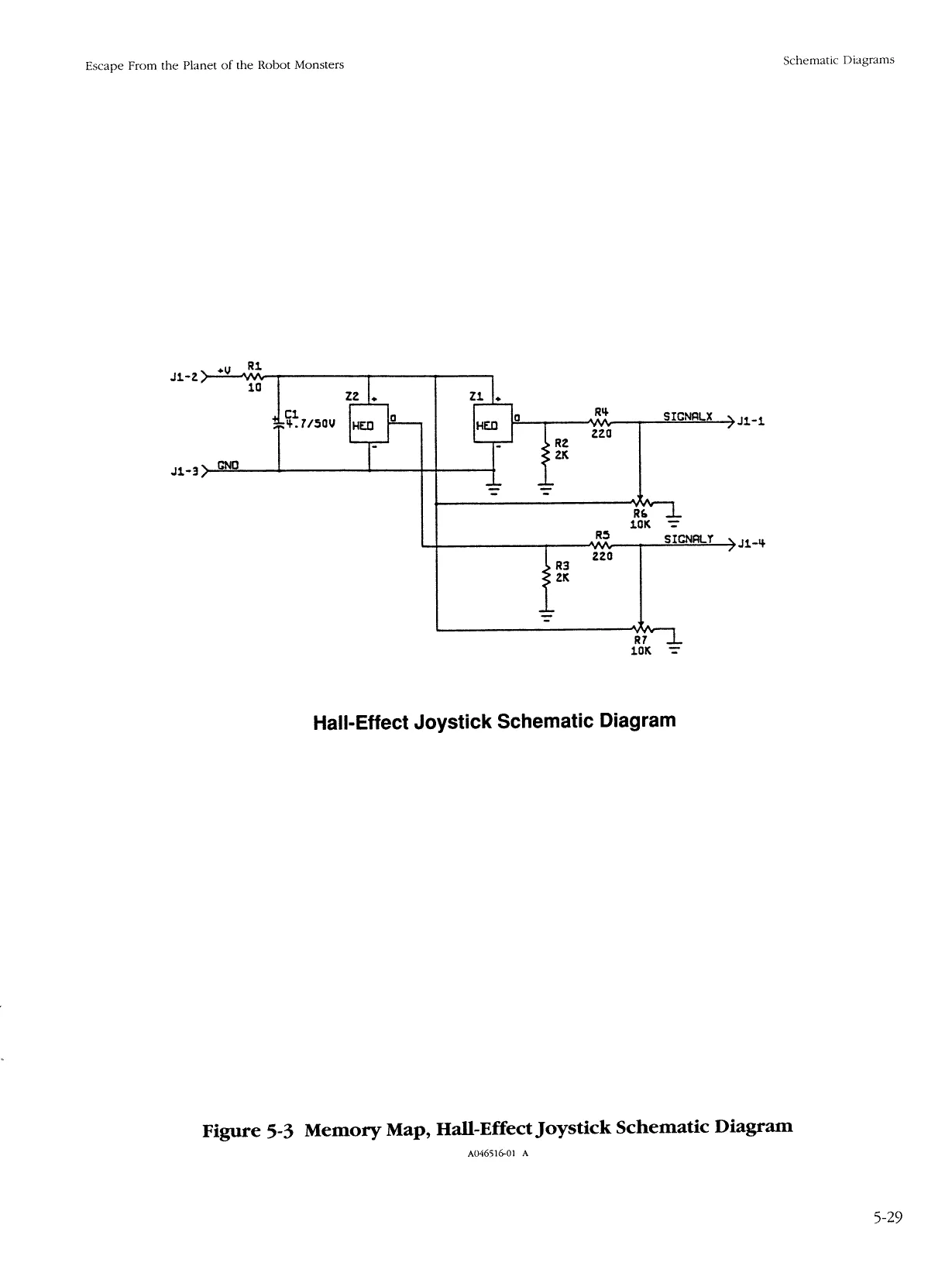
This page is a drawing, shown as the original scan.
AN ATARI GAMES Escape From the Planet of the Robot Monsters" Statistics Sheet
Statistics Screen
| Plyr 0 Coins: | 1 Plyr Mins: | Error Count: | —__ |
Plyr 1 Coins: 2 Plyr Mins:
| Total Games | L Plyr Mins: | oe | Total Coins: | _ |
| 0 Plyr Mins: | R Plyr Mins: | Avg Time/Coin: | ee |
Histogram Screens
| Histogram 1 | Histogram 2 | Histogram 3 | Histogram 4 | ||||
| New Game | Continuations | Level Quit At | Deaths Per Level | ||||
| O- 59 | a | 0- 59 | —___ | 0 | _— | 0 | ee |
| 60- 89 | 60- 89 | a | 1 | _ | 1 | —_— | |
| 90-119 | 90-119 | 2 | 2 | a | |||
| 120-149 | 120-149 | 3 | 3 | - | |||
| 150-179 | 150-179 | 4 | 4 | ——_ | |||
| 180-209 | 180-209 | 5 | 5 | —__ | |||
| 210-239 | 210-239 | 6 | 6 | ||||
| 240-269 | 240-269 | 7 | 7 | ||||
| 270-299 | 270-299 | 8 | 8 | ——_ | |||
| 300-329 | —_—— | 300-329 | — | 9 | ——_ | 9 | —_— |
| 330-359 | —_ | 330-359 | —_ | 10 | —_—— | 10 | —_— |
| 360-389 | 360-389 | 1 | _— | 1 | —_— | ||
| 300-419 | 300-419 | 2 | _ | 12 | _ | ||
| 420-449 | 420-449 | 13 | 13 | — | |||
| 450-479 | 450-479 | 14 | 14 | ||||
| 480-509 | 480-509 | 15 | 15 | ——_ | |||
| 510-539 | 510-539 | 16 | a | 16 | —— | ||
| 540-569 | 540-569 | VW | _ | 7 | —_— | ||
| 570-599 | 570-599 | 18 | _ | 18 | —_ | ||
| 600 & up | 600 & up | 19 & up | 19 & up | _ |
Eee eleelelelrelelelelelrelelelelel eel felrelrelfelelreltel
Seller warrants that its printed-circuit boards and parts thereon are free from defects in material and workmanship under normal use and service for a period of ninety (90) days from date of shipment. Seller warrants that its video displays and laser-video disc players (in games supplied with displays and videodisc players) are free from defects in material and workmanship under normal use and service for a period of thirty (30) days from date of shipment. None of the Seller's other products or parts thereof are warranted. If the products described in this manual fail to conform to this ranty, Seller's sole liability shall be, at its option, to repair, replace, or credit Buyer's account for such products which are returned to Seller during said warranty period, provided:
- Seller is promptly notified in writing upon discovery by Buyer that said products are defective;
- Such products are returned prepaid to Seller's plant; and
- Seller's examination of said products discloses to Seller's satisfaction that such alleged defects existed and were not caused by accident, misuse, neglect, alteration, improper repair, installation, or improper testing. In no event shall Seller be liable for loss of profits, loss of use, incidental or consequential damages. Except for any express warranty set forth in a written contract between Seller and Buyer which contract supersedes the terms herein, this warranty is expressed in lieu of all other warranties expressed or implied, including the implied warranties of merchantability and fitness for a particular purpose, and of all other obligations or liabilities on the Seller's part, and it neither umes nor authorizes any other person to assume for the Seller any other liabilities in connection with the sale of products by Seller.
Paella eel elle elle elel el elrelrelfelrelrel
The use of any non-Atari parts may void your warranty, according to the terms of the warranty. The use of any non-Atari parts may also adversely affect the safety of your game and cause injury to you and others. Be very cautious in using non-Atarisupplied components with our games, in order to ensure your safety. Atari distributors are independent, being privately owned and operated. In their judgment they may sell parts or accessories other than Atari parts or accessories. Atari Games Corporation cannot be responsible for the quality, suitability or safety of any non-Atari part or any modification including labor which is performed by such distributor.
This page carries no recoverable text. It is a drawing or a photograph. See the original scan.