Elevator Action
Elevator Action (BA3, 4 PCB version, 1.1) (Taito Corporation, 1983) · Manual · 70 pages · 34 sections · original scan
72-00042-001
Ware] © 1983 Trade Marks of Taito America Corporation
This page carries no recoverable text. It is a drawing or a photograph. See the original scan.
“ELEVATOR ACTION”™ UPRIGHT TABLE OF CONTENTS
- “ELEVATOR ACTION”™ GAME SET-UP A. GAME FEATURES .... 1... ee ee ee 1 B. INTRODUCTION. .. 2... 2 ee 1 C. GAME INSTALLATION .. 1.2.2... eee ee 1 D. DIP SWITCH AND VOLUME CONTROL SETTINGS ....... 1-3
- MAINTENANCE A. CLEANING. 2.0.00 eee ees 3 B. FUSE REPLACEMENT ...........2. 0000000 vveue 3 C. VIDEO MONITOR REMOVAL .............00000008 3 D. PRE GAME INSTALLATION ...............0000005 4 E. COVERGLASS REMOVAL ............. ee eee 4 F. . PRINTED CIRCUIT BOARD REPLACEMENT. ............ 4
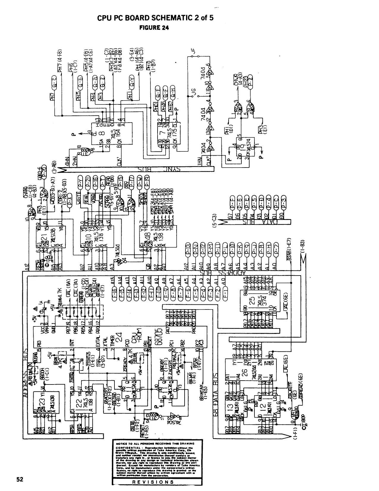
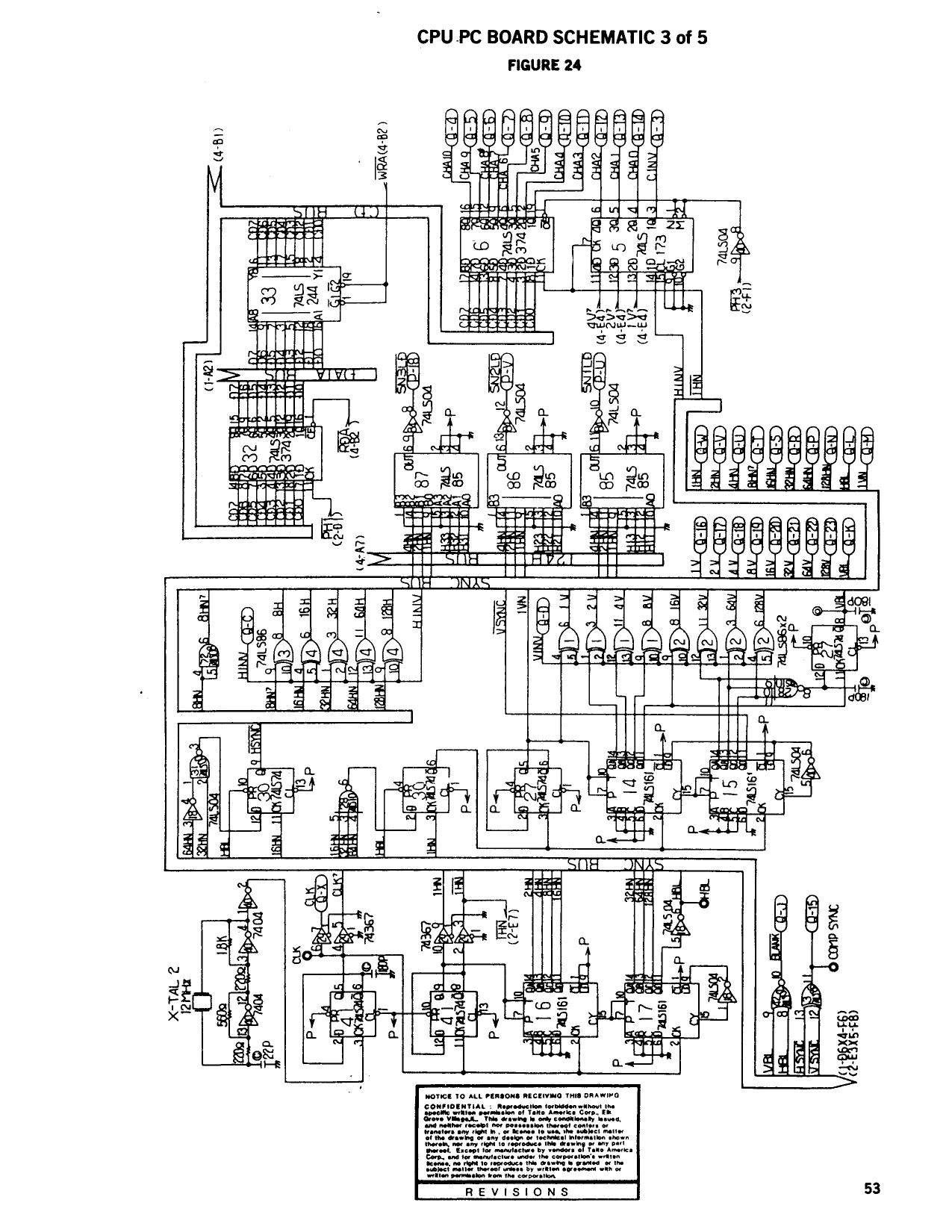
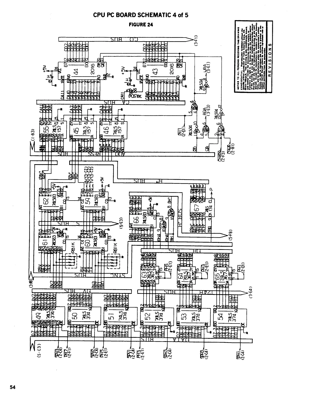
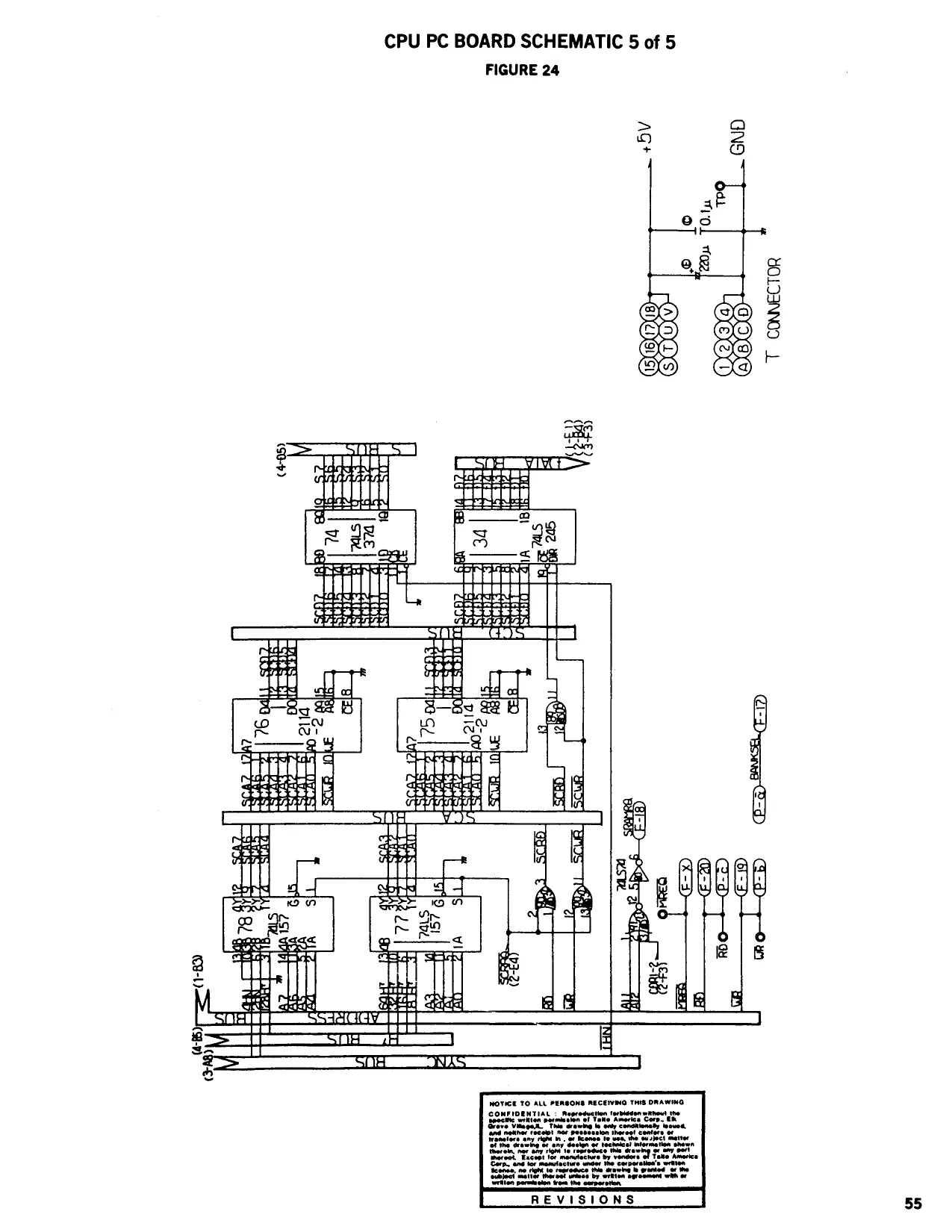
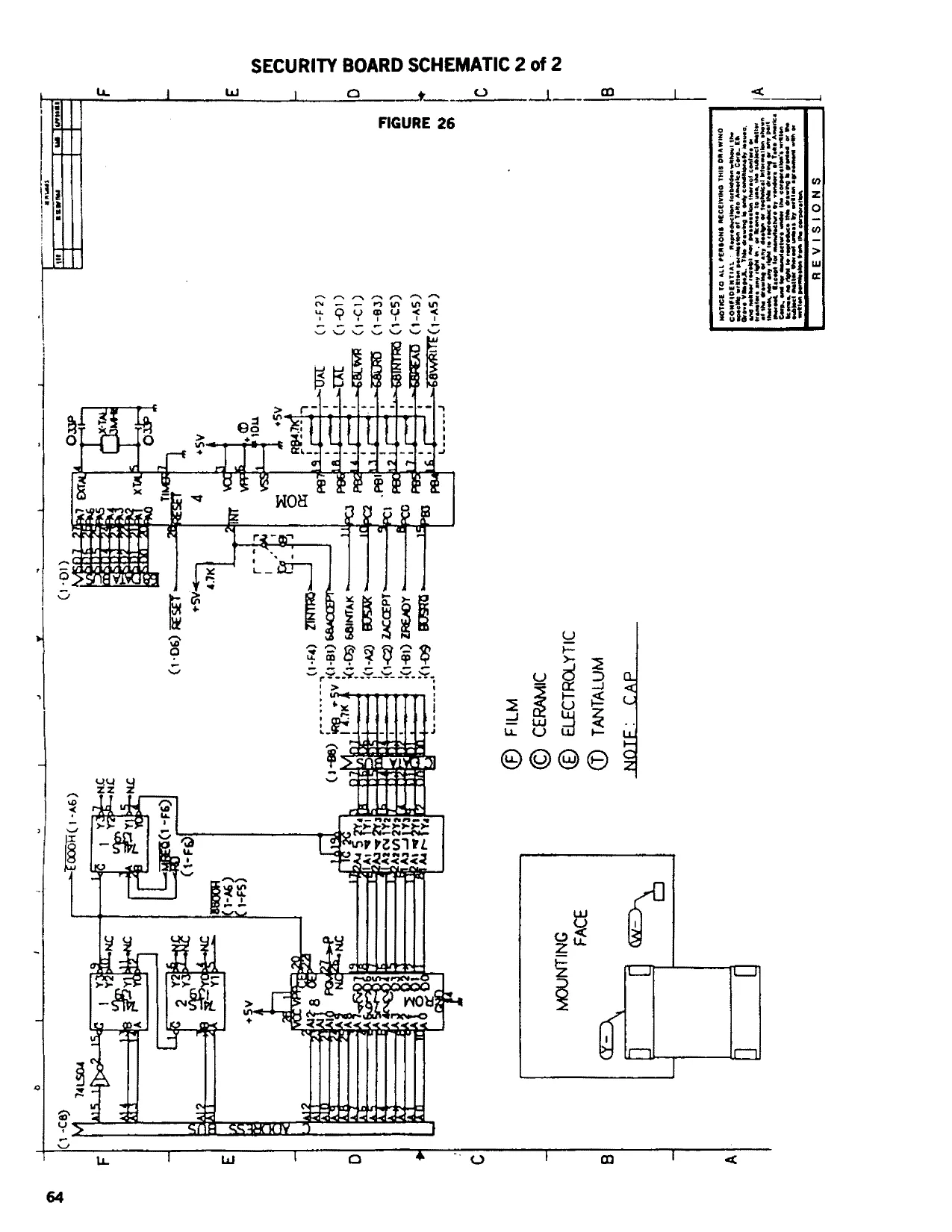
- ILLUSTRATION & PARTS LISTS FIGURE 7 INCANDESCENT PANEL .............. wee 5 FIGURE 8 4-WAY JOYSTICK .............0.05 Meee 6 FIGURE 9 CONTROL PANEL ...............0.0000. 7 FIGURE 10 DOOR ASSEMBLY SJC-3...............000- 8 FIGURE 11 DOOR ASSEMBLY SJC-2...............00. 9-10 FIGURE 12 COINDOOR ........ eee eee 11-12 FIGURE 13 COIN DOOR ..............0 0c eee ues 13-14 FIGURE 14 COINDOOR .............. bee eee 15-16 FIGURE 15 CABINET ASSEMBLY REAR VIEW........... 17-18 FIGURE 16 CABINET ASSEMBLY FRONT VIEW.......... 19-20 FIGURE 17 POWER SUPPLY COMPONENT LAYOUT....... 21-23 FIGURE 18 POWER SUPPLY SCHEMATIC 1 of 1........... 24 FIGURE 19 FILTER BOARD ..............0.000005% 25 FIGURE 20 ROM BOARD (4 BOARD SYSTEM) .......... 26-28 FIGURE 21 ROM BOARD (5 BOARD SYSTEM) .......... 29-31 FIGURE 22 GAME BOARD (4 & 5 BOARD SYSTEM) ....... 32-41 FIGURE 23 VIDEO BOARD (4 & 5 BOARD SYSTEM)....... 42-48 FIGURE 24 CPU BOARD (4 BOARD SYSTEM)........... 49-55 FIGURE 25 CPU BOARD (5 BOARD SYSTEM)........... 56-60 FIGURE 26 SECURITY BOARD (5 BOARD SYSTEM) ....... 61-64
- WIRING DIAGRAM FOLDOUT
“ELEVATOR ACTION”™ UPRIGHT
1, GAME SET-UP
A. GAME FEATURES TAITO AMERICA CORPORATION’S “ELEVATOR ACTION”™ upright game is housed in a compact and highly serviceable cabinet with many added features. A larger designed cash box has been incorporated into the design of this cabinet. By putting wheels on the cabinet, moving the game from one location to another is made much easier. The Control Panel has a polycarbonate overlay, so cigarette marks and mars can easily be wiped clean. This overlay can be replaced if necessary. The Marquee and Coverglass are made of fully Tempered Glass to minimize breakage. The Back Service Door houses all the P.C. Boards for the system making servicing of the game, if needed, much easier. Lighted instructions are provided to further enhance the game and attract players, by making the instructions easier to read. B. INTRODUCTION TAITO AMERICA CORPORATION'S “ELEVATOR ACTION”™ upright game is designed for one or two players. Agent 17 (code name “Otto”) is to secure the top secret documents from the security building. The enemy spies are in pursuit and their orders are to stop him at any cost. Having made it to the top of a 30 story building Agent 17 has to make his way down to the basement to get to the getaway car and save the documents. Enemy spies are everywhere and the documents are hidden behind the red doors (bonus points awarded). He has to open the door and keep moving. If either of them shoots the lights out there will be a temporary blackout. If Otto finds himself on top of the elevator the player will not be able to control the elevator. If he gets caught in the elevator he is a sitting duck and cannot duck the bullets. By using the escalator he can reach the basement quicker. Otto can defeat his enemy by jump kicking or firing at them. Help Otto to grab all the documents and escape the spies.
C. GAME INSTALLATION TAITO AMERICA CORPORATION'S “ELEVATOR ACTION”™ upright game is shipped ready for operation, but a last visual check should be made to insure the game is in good condition. Please verify the following before turning the game on. Check the exterior of the game for shipping damage, chips, dents, or broken parts.
- Open the Rear Service Door and check for any interior damage.
- Make sure there isn’t any damage to the wiring.
- Check the Printed Circuit Boards, making sure there is no damage to the components.
- Check fuses to make sure they are firmly in their holders.
- Check for loose foreign objects, especially metal objects which may cause electrical problems.
- Check Plug-in Connectors making sure they are firmly in their sockets.
- Check Switches making sure they are not damaged. The Video Monitor is properly adjusted before shipping. If there are any adjustments necessary, refer to our Video Monitor Manual (72- 0025-001). This manual contains all the manufacturers recommendations for adjusting the video monitor. POWER REQUIREMENTS TAITO AMERICA CORPORATION’s “ELEVATOR ACTION”™ upright game is shipped ready for operation at 120VAC, 60Hz with a power consumption of approximately 250 Watts.
LOCATION SPACE Depth 35” (87.5cm) Width 24” (61cm) Height 68” (171cm) Weight 300 Ibs. (Packaged Weight) D. DIP SWITCH AND VOLUME CONTROL SETTINGS DIP SWITCHES TAITO AMERICA CORPORATION'S “ELEVATOR ACTION” game provides the following option switches. See Figure 1. These option switches can be found on the Game Board (99-AA017808).
A B c (hy (ay (Eo (DIP SW) —
, VR-BGM (SOUND) VR-MAIN in)
col>
DIP SWITCH A
SETTING BONUS POINTS| 10,000 pi FOR ADDITIONAL] 15,000 pts PLAYER 20,000 pts 25,000 pts FREE PLAY NORMAL FREE PLAY NUMBER OF 3
PLAYERS 4
SCREEN INVERSION GAME COCKTAIL TABLE STYLE. UPRIGHT.
DIP SWITCH B
SETTING POSITION
1 Coin - 1 Play on 1 Coin - 2 Plays off 1 Coin - 3 Plays on 2 Coins- 1 Play on 3 Coins- 1 Play off_| on 4 Coins- 1 Play on | off | on [ off _| on
DIP SWITCH C
VOLUME CONTROL SETTING The Volume increases by turning the potentiometer as indicated in Figure 2.
VOLUME CONTROL LOCATIONS
MAIN BACKGROUND
POWER ON OFF SWITCH
The power on/off switch is located in the front lower left hand corner of the cabinet.
- MAINTENANCE All games require a certain amount of maintenance to keep them in good condition. A periodic check of mechanical controls would be benefical to guarantee your game will be profitable. A. CLEANING The exterior of the game, all metal parts and all plastic parts can be cleaned with an non-abrasive cleanser. Caution should be used when cleaning the plastic, a dry cloth can cause scratches and result in a foggy appearance. B. FUSE REPLACEMENT This game contains 8 fuses. Seven of these fuses can be found ‘on the Power Supply Assembly, five (5) are on the PCB and two
- are on the Power Supply Bracket. One(1) is located at the bracket where the AC line cord comes into the cabinet. See Figure for location of these fuses. FUSE REPLACEMENT C. VIDEO MONITOR REMOVAL If you need to remove the Video Monitor follow the instructions listed below:
NOTICE:
“This equipment complies with the requirements of Part 15 of FCC Rules for a Class A computing Device. Operation of this equipment in a residential area may cause unacceptable interference to radio and T.V. reception requiring the operator to take whatever steps are necessary to correct the interference.”
- Disconnet the power from the line voltage.
- Disconnect the Monitor cable connector.
- While holding the monitor bracket take out the two rear side bolts, one on each side of the cabinet.
- Carefully lower the mounitor on to monitor stops.
- Remove the four mounting bolts and disconnect the braided ground wire.
- Slide the monitor out by pulling the monitor toward you.
Use extreme caution and do not touch electrical parts of the Monitor Yoke area with your hands or with any metal object in your hands! High voltages may exist in any Monitor, even with power disconnected.
MONITOR REMOVAL
D. PRE GAME INSTALLATION The following precautions should be followed when installing the game.
- Avoid rough handling of the game, the picture tube is fragile.
- Install the game on a level surface.
- Avoid installing the game where it may receive excessive sunlight or heat, to protect the game from rising internal temperatures.
- Do not install in a damp or dusty location.
- For a short time after connecting the power to the game, the picture may be temporarily distorted. The monitor's purity is affected by the earth's magnetic field, causing a variation of color. By turning the game on for 10 or 15 seconds and then off for 20 to 30 minutes the automatic degaussing circuit applies a degaussing field the edges of the monitor. Doing this several times will correct the problem. Another way to correct this problem is to purchase a degaussing coil or bulk tape eraser at any Electronics store. This will help to immediately demagnetize the Video tube. Caution must be used with a degaussing coil so the magnetic field of the degaussing coil is not allowed to become too intense at any one place on the picture tube thereby causing a localized color distortion. If you move the game to another location after degaussing the problem may reappear. Refer to Monitor Manual E. COVERGLASS REMOVAL Jo remove the Coverglass follow the Instructions listed below:
- Remove the contro! panel by reaching up through the Coin Door and unlatching the latching clamps.
- Lift the Coverglass out. The Coverglass can now be easily removed from the front of the game with no screws. To replace the coverglass simply reverse the above procedure.
- Be sure you are holding the glass firmly to ensure against any chipping or breakage. F. PRINTED CIRCUIT BOARD REPLACEMENT You may wish to remove the “ELEVATOR ACTION”™ Printed Circuit Boards for servicing. Refer to Figure 6. The Elevator Action Printed Circuit Boards are located on the inside of the rear Service Door for easy access. To remove the boards the following steps should be followed:
- Open the rear service door, the power will automatically be removed by the Interlock Switch located on the inside of the door frame.
- Remove the speed nuts from studs and lift off shield.
- Disconnect the connectors G, H and T from the boards.
- Loosen and turn the Stop Bracket and slide the boards out of the board guides.
PRINTED CIRCUIT BOARD REPLACEMENT
Co
INCANDESCENT PANEL
TAITO ITEM PART NO. DESCRIPTION 1 27-00006-001 | LAMP #47 2 26B00009-001 | BAYONET BASE SOCKET 61000112-001 | MARQUEE LIGHTING PLATE
4-WAY JOYSTICK (63-00032-004)
TATIO PART NO. DESCRIPTION 63B00031-001 [BALL & SHIFT 63A00033-001 [MASK 63C00027-002 MOUNTING PLATE 62A00002-001 SHOCK MOUNT PLATE 63A00028-002 SWITCH PLATE 63A00030-002 ACTUATOR 61A00078-001 “L" BRACKET 63C€00029-001 SWITCH SPACER 29B00016-002 LEAF SWITCH, SHORT 63A00029-001 SPACER =]S]o]o]s)ofalaloln|—]a =
59B00020-017 “E" RING
CONTROL PANEL
TAITO PART NO. ‘DESCRIPTION 63B00024-001 [PUSH BUTTON WHITE 42B00108-001 [CLEAT, WOOD 61A00015-001 _|STRIKE HOOK 42-00150-001 _|MOUNTING PLATE 61-00216-001 _|METAL CONTROL PANEL 66-00003-001 _|CONTROL PANEL OVERLAY 63-00025-001 _|SWITCH SUPPORT 54A07001-008 | NUT, STAMPED 5/8-11 29B00016-001 [SWITCH LEAF o
DOOR ASSEMBLY SJC-3
TAITO
| {TEM | —_|PART NO. | DESCRIPTION |
1 61-00142-001 _| LOCK ROD ASSEMBLY
| 2 | 08-00132-001 | _|GAME BOARD SET |
| 3 | 99-AA017808 | _|GAME PCB |
| 4 | 99-KNO0004 | CPU PCB |
5 99-AAO17810 | VIDEO PCB
| 6 | 99-KNO0005 | ROM PCB |
*6A _|08-00116-003 | SECURITY BOARD 7 08-00120-001 _| FILTER PCB
| *8 | 07-00262-001 | _|BRACKET PC BOARD, BOTTOM |
| 9 | 61A00014-001 | _|“L" BRACKET |
10 07-00261-001 _| BRACKET PC BOARD, TOP
| 1 | 63-00140-001 | _|PCB SHIELD |
12 61-00111-001 _| BRACKET, LOCK ROD. 61-00229-001 HINGE 42-00144-001 BACK DOOR 61-00300-001 GROUND PLATE. 59-00016-001 SPACER 59-00057-001 SPEED NUT
- Item not shown on drawing.
12—_ DOOR ASSEMBLY SJC-2
DOOR ASSEMBLY SJC-2
| 7 | 59-00057-001 | _|SPEED NUT |
TAITO “|
| ITEM | [PART NO. | DESCRIPTION |
| 1 | |61-00142-001 | [LOCK ROD ASSEMBLY |
2 |08-00130-001 _ [GAME BOARD SET 3___[99-AA017808 _ [GAME PCB + 4 ___ |99-Aa017809__ [CPU PCB
| [8 | [99-aao17810 | [VIDEO PcB |
| 6 | __|99-AA017811__ | [ROM PCB |
7 [08-00120-001 _|FicteR PCB
| 8 | __[07-00131-001 | [BRACKET PCB, TOP |
9 [61A00014-001_["L” BRACKET 10* _|07-00248-001 _| BRACKET PCB, BOTTOM
| 11 | [63-00121-001_| | PCB SHIELD |
| 12 | [61-00111-001__| | BRACKET, LOCK ROD |
13 |61-00229-001_|HINGE 14 |42-00134-001 | BACK DOOR 15 ee GROUND PLATE |
| 16" | _|59-00016-001_ | | SPACER |
- Item not shown on drawing.
COIN DOOR
COIN DOOR
TAITO
| ITEM | | PART NO. | DESCRIPTION | REFERENCE |
| 1 | 61-00270-001 ws FRAME | 15-8039 | |
| 2 | 61-00271-001 | _|DOOR | 15-8038 |
| 3 | 61-00272-001 | [HINGE | 30-9125 |
| 4 | 61-00273-001 _| TAITO NAME PLATE | 15-8115 | |
| 5 | 63-00124-001 | {COIN ENTRY SLOT | 15-8074 |
| 6 | 63-00125-001 | {PUSH BUTTON COVER | 15-8072 |
7 63-00126-001 _ {PUSH BUTTON
| 8 | 58-00007-001 | _|COMPRESSION SPRING | |
| 9 | 63-00127-001 | | REJECT LEVER | |
| 10 | 61-00274-001 | | COIN CHUTE | 15-8075 |
| ll | 63-00128-001 | _|COIN RETURN DOOR | 15-8083 |
| 12 | 61-00275-001 | | LOCK OUT COIL | 15-8081 |
| 13 | 61-00276-001 | | GUARD | 15-8092 |
| 14 | 63-00129-001 _| COIL BRACKET | 15-8080 | |
| 15 | 23-00003-001 | COIN RETURN BOX | 15-8091 | |
| 16 | 63-00130-001 | _|SWITCH COVER | 15-8043 |
| V7 | 29-00036-001 | _|SLAM SWITCH | 15-1255 |
| 18 | 59-00055-001 _| PLASTIC COIN ACCEPTOR .25 | 31-4014 | |
| 19 | 63-00131-001 | _|COIN ACCEPTOR RETAINER | 15-8086 |
| 59-00020-025 | 1/4" | ERING | 30-0731 |
58-00008-001 _| EXTENSION SPRING 30-7372
| 22 | 61-00277-001 | _|SERVICE SWITCH BRACKET | 15-8030 |
| 23 | 29-00037-001 | _|SERVICE SWITCH | 23-1339 |
| 07-00242-001 | _|LOCK 5/8” ASSEMBLY | 34-1855 | |
| 07-00243-001 | _|LOCK CAM ASSEMBLY | 55-2909 | |
| 26 | 61-00278-001 | {LOCK CAM PLATE | |
| 27 | 61-00279-001 | _|WIRE FORM (COIN SWITCH) | |
| *28 | 09-00258-001 | _|DOOR CABLE ASSEMBLY | |
| 33-00002-001 | _|COIN COUNTER 6VDC | 31-4550 | |
| 30 | 27-00008-001 | _|LAMP #1815 | 21-1815 |
| 31 | 26-00019-001 | _|LAMP SOCKET 25B4-L187 | 15-9419 |
29-00041-001 | SWITCH 23-1347 51-02002-002 _|#6-32 X1/4 PR PH SCREW 51-02002-006 _|#6-32 X 1/2 PR PH SCREW 79-50034-001 _|.25 PRICE DECAL. Eorrereeeeet
- Item not shown on drawing.
This page carries no recoverable text. It is a drawing or a photograph. See the original scan.
COIN DOOR
TAITO |
| ITEM | | PART NO. | DESCRIPTION | REFERENCE |
| 1 | Te1-00042-001 | COIN DOOR ONLY (2 COIN) | 404341 |
| 2 | 63-00015-001 | _|COIN RETURN BUTTON | 904591 |
| [3 | 79-50004-001 | _|US ,25 PRICE DECAL | 904703 |
| 4 | 63-00016-001 | _|COIN RETURN BUTTON COVER | |
| 5 | 07-00025-001 {LOCK ASSEMBLY | 904707-1 | |
| 6 | 51-01051-003 | [SCREW #4 X 5/16 SL PH TYPE B | 345-4-5 |
| 7 | 63-00011-001 | _|COIN BUTTON HOUSING | 904588 |
| 8 | 51-02051-002 _| SCREW #4-40 X 1/4 SL PH | 325-4-4 | |
| 9 | 63-00012-001 | _|COIN RETURN BEZEL | 904590 |
| 10 | 63-00013-001 | [COIN RETURN COVER | 904599 |
1 61-00040-001 _ | COIN DOOR FRAME 11 5/8 X 13 3/8 MOUNTS INA 10 3/8 X 12 3/16 OPENING
| 12 | 54-01005-001 | _|HEX NUT 1/4-20 | 406-416 |
| 13 | 51A03003-113 | _|CARRIAGE BOLT | 904734 |
| 14 | 07-00026-001 | _|LOCK CAM ASSEMBLY | 404357 |
COIN DOOR
COIN DOOR
TAITO
| {TEM | | PART NO. | DESCRIPTION | REFERENCE |
| 1 | 07-00027-001_| | INNER PANEL W/LEVERS | 404429 SUB ASSEMBLY | |
2 54-03013-001 | NUT #8-32 400-8
| * | 09-00017-001 | _|CUSTOM HARNESS ASSEMBLY (SGL COIN) |
| * | 09-00017-002 | _|CUSTOM HARNESS ASSEMBLY (DUAL COIN) |
3 61B00113-001 | SERVICE SWITCH BRACKET 4 29-00022-001 | SERVICE SWITCH
| 5 | 54-03011-001 | | NUT #4-40 | 904762 |
| 6 | 63-00014-001 | SWITCH COVER | 100-6-3 | |
| 7 | 51-02052-001 | SCREW #6-32 X 3/16 SS PH | 404354 | |
| 8 | 23-00001-001_|C.R.E.M. COIL ASSEMBLY | 100-4-12 | |
| 9 | 51-02052-001 | SCREW #6-32 X 3/16 SS PH | 100-4-12 | |
| 10 | 59-00019-001 | RETAINER | 900651 | |
| 11 | 28-00029-001 | [SILVER SWITCH FOR US .25 | 904710-1 |
| 12 | 29-00007-001 | SWITCH | 904845 | |
| 13 | 61-00044-001 | [COIN CHUTE | 904701 |
| 14 | 61-00045-001 | _|COIN RETURN BOX | 904598 |
| 15 | 61-00025-001 | [SWITCH &C.R.E.M. COIL | 404428 |
| 16 | §9-00018-001 | |.25 ACCEPTOR | 5301-10 |
| 17 | 51-02051-006 | _|SCREW 4-40 X 3/8 SS PH | 110-4-6 |
| 18 | 27-00003-001 | MINATURE BAYONET BASE LAMP 904717 * 26-00006-001 LAMP SOCKET | 904717 | |
| 19 | 27-00003-001_|#47 LAMP (6.3 VOLT) | 904716 | |
| 20 | 61-00048-001_|COIN INLET CHUTE | 904418 | |
| 2l | 61-00047-001_| | RIGHT HALF OF COIN INLET | 904594 CHUTE |
| 22 | 54-00001-001 | “U" TYUPE FASTENER | 904712 | |
| 23 | 51-02051-006 | SCREW 4-40 X 1/2 SS PH | 116-4-8 | |
| 24 | 29-00006-001 | _|SLAM SWITCH ASSEMBLY | 904704 |
| 25 | 33-00002-001 | _|COIN METER | |
| 26 | 63-00155-001 | |COIN REJECT LEVER | 904583 |
- Item not shown on drawing.
CABINET ASSEMBLY REAR VIEW
CABINET ASSEMBLY REAR VIEW
TAITO
| ITEM | | PART NO. | DESCRIPTION |
| 1 | [21-00003-001 | _|SPEAKER |
2 [61B00027-001 | SPEAKER GRILL 3 _[07M00042-001 | A/C LINE CORD ASSEMBLY
| 4 | [61-00114-001 | _|INTERLOCK BRACKET |
*4A _|59-00046-001 _| SWITCH BARRIER 5 29B800015-001 | INTERLOCK SWITCH
| 6 | 07M00039-001 | {POWER SUPPLY |
| 7 | 61C00054-001 | {CASH BOX LID |
| 8 | 61D00060-001 | _|CASH BOX |
| 9 | 63R00010-001 | {CASH TRAY (ONLY) |
| 10 | 63-00019-001 | _|CASH TRAY SEPARATOR |
| 11 | 61B00039-001 | [CASH TRAY HANDLE |
| 12 | 42C00013-001 | [MONITOR SUPPORT CLEAT |
| fa | 61D00208-001 | {MOUNTING BRACKET |
| 14 | 31-00013-001 | _|19" COLOR MONITOR |
| 15 | 26-00008-001 | _|SOCKET LAMP CLIP-ON MINI BAY |
16 27-00006-001 | #47 BULB
| 17 | 04-00037-002 | [LOCK ASSEMBLY |
18 44-00001-001 _| WHEEL ASSEMBLY
| "19 | 07-00041-001 | _|HEAT SINK ASSEMBLY | |
| *20 | 08-00007-001 | _|REGULATOR BOARD | | |
*21 18-00003-001 _ | TRANSFORMER
- Item not shown on drawing.
CABINET ASSEMBLY FRONT VIEW
CABINET ASSEMBLY FRONT VIEW
TAITO ITEM _|PARTNUMBER | DESCRIPTION
| 1 | |07M00055-002 | INCANDESCENT PANEL |
2 [63800006-003_[“U" CHANNEL BRACKET
| 3 | [47-00012-017_ | [MARQUEE | |
| 4 | __[61C00115-001 | [MARQUEE RETAINING BRACKET | __ |
| 5 | [47-00016-008 | _[COVERGLASS | ___ |
| 6 | [63-00053-001 | [SHROUD | _ |
| 7 | [07-00285-001 | _[COIN DOOR | _— |
| 8 | [61B00113-001 | [SWITCH BRACKET | |
| 9 | [07-00118-001 | [SERVICE SWITCH ASSEMBLY | |
| 10 | [29-00022-001 | SLIDE, CENTER RETURN SWITCH | |
| 11 | [59-00008-001 | _[LATCHING CLAMP | |
| 12 | [63800002-004 | _[*T” MOLDING | |
| 13 | |29400023-001_| | POWER ON/OFF SWITCH |
‘ 09-00227-001 | MAIN HARNESS CABLE
| : | 09-00043-002_| | SPEAKER CABLE |
| 14 | [41-00024-001_ | [FINISHED CABINET |
| 15 | [07-00281-001 | [CONTROL PANEL ASSEMBLY |
- Item not shown on drawing.
POWER SUPPLY COMPONENT LAYOUT
om oD ap am | a
+e O 8G )8088@) ull ele “S
g Jalal c7 ED! LeD2k4 ag
“7 BEE ve Ci * 0 gage
S ©) ceae ee
419)
° + “
° te, o ha + ° ge E S22 B gs 3 3 ow ig os
POWER SUPPLY BOARD
TAITO TAITO SYM | PART NO. DESCRIPTION SYM |PART NO. DESCRIPTION
| R1__[11-00001-102|RES, 1.0K 1/4W 5% | C8 | __|12-30001-105 | CAP, TANT luf 35V | |
| R2 | [11-00001-512 | RES, 5.1K 1/4W 5% | C9 | __|12-20003-209 |CAP, ELECTRO 20,000uf 30V |
R3__|11-00001-183 | RES, 18K 1/4W 5% C10_|12-10001-332 |CAP, CER .0033uf 50V
| R4 | 11-00001-224 |RES, 220K 1/4W 5% | C11 | _|12-30001-476 |CAP, TANT 47uf 15V |
{R5_[11-00001-472 [RES, 4.7K 1/4W 5% C12_|12-30001-105 |CAP, TANT 1.uf 35V 50V
| R6 | _[11-00001-222 |RES, 2.2K 1/4W 5% | C13_|12-10004-103 |CAP, CER .Oluf 50V | |
| R7_[11-10001-101 |RES, 100 1/4W 5% | C14 | |12-10001-102 |CAP, .0Oluf SOV | |
| R8_[11-00001-102 |RES, 10K 1/4W 5% | C15 | |12-30001-476 |CAP, TANT 47uf 15V | |
| RQ | _{11-00001-472 |RES, 4.7K 1/4W 5% | C16 | |12-20002-108 |CAP, ELECTRO 1,000uf 30V |
| R10 | |11-10001-101 |RES, 100 1/2W 5% | C17_|12-30001-225 |CAP, TANT 2.2uf 25V | |
| Rll ‘{11-30001-015) RES, .15 4W 5% | C18 | |12-30001-225 |CAP, TANT 2.2uf 25V | |
| R12 | }11-30001-015 | RES, .15 4W 5% | C19 | |12-30001-105 |CAP, TANT luf 35V |
| R13 | 11-00001-472 | RES, 4.7K L/4W 5% | F1__|24-00003-010 | 10A FUSE | |
| R14 | |11-00001-222 |RES, 2.2K 1/4W 5% | F2__|24-00003-010 | 10A FUSE | |
| R15 | |11-00001-222 |RES, 2.2K 1/4W 5% | F3 | _|24-00003-003 | FUSE, 2A |
| R16 | |11-60001-252 |RES, VAR 2.5K L/4W 20% | F4 | ‘[24-00003-004 FUSE, 4A |
R17_|11-00001-222 |RES, 2.2K 1/4W 5% F5__|24-00003-004 | FUSE, 4A
| R18 | |11-60001-102 |RES, VAR 1.0K 1/4W 20% | BR1 | |13-00100-025 | DIODE BRIDGE 25A, 100V |
| R19 | |11-00001-511 |RES, 510 1/4W 5% | BR2 | _|13-00100-012 | DIODE BRIDGE 12A, 100V |
| R20 | |11-10001-470 |RES, 47 1/2W 5% | BR3 | |13-00100-002 | DIODE BRIDGE 2A, 100V |
| R21 | |11-00001-162 | RES, 1.6K 1/4W 5% | D1 | _|13-14002-001 | DIODE IN4002 |
| R22 | |11-00001-103 | RES, 10K 1/4W 5% | 02 | _|13-14002-001 | DIODE IN4002 |
| R23 | |11-00001-472 | RES, 4.7K L/4W 34 | D3 | _|13-10752-001 | DIODE ZENER IN752 |
| R24 | |11-00001-222 | RES, 2.2K 1/4W 5% | D4 | __|13-14002-001 | DIODE IN4002 |
| R25 | |11-60001-102 | RES, VAR 1.0K 1/4W 5% | D5 | _|13-14002-001 | DIODE IN4002 |
| R26 | |11-00001-472 | RES, 4.7K. 1/4W 5% | D6 | __|13-14002-001 | DIODE IN4002 |
| R27 | |11-00001-222 |RES, 2.2K 1/4W 5% | [ez | 13-10964-001 | DIODE ZENER IN964 |
| R28 | [11-60001-252 [RES, VAR 2.5K 1/4W 20% | D8_|13-14002-001 | DIODE IN4002 | |
| R29 | |11-00001-472 |RES, 4.7K 1/4W 5% | D9 | _|13-14002-001 | DIODE IN4002 |
R30_|11-00001-122 |RES, 1.2K 1/4W 5% D10_|13-14002-001 | DIODE IN4002 |
| R31 | |11-10001-470 | RES, 47 1/4W 5% | D11_{13-14002-001 | DIODE IN4002 |
R32_|11-30001-015 | RES, .15 4W 5% D12_|13-14002-001 | DIODE IN4002 R33 ‘[i-00001-222 RES, 2.2K /4W 5% : LED1]13-00001-001 |LED (RED)
| R34 | }11-00001-122 |RES, 1.2K 1/4W 5% | LED2|13-00001-001 [LED (RED) |
| R35 | |11-00001-511 | RES, 510 1/4W 5% | LED3]13-00001-001 LED (RED) |
R36 | 11-00001-222 |RES, 2.2K 1/4W 5% LED4]13-00001-001 [LED (RED)
| R37_|11-00001-104 |RES, 100K 1/4W 5% | U1 | __|15-62500-001 OPTO COUPLER H11AA2 |
R38 | 11-00001-103 |RES, 10K 1/4W 5% U2__|15-50556-001 [TIMER (DUAL) 556
| R39 | |11-00001-224 |RES, 220K 1/4W 5% | U3 | _|15-50723-001 [VOLTAGE REGULATOR 723 |
| C1__|12-30001-225 |CAP, TANT 2.2uf 25V | U4 | _|15-50723-001 | VOLTAGE REGULATOR 723 |
C2__|12-10004-103 |CAP, CER .Oluf 50V REG1] 15-57912-001 [VOLTAGE REGULATOR 7912
| C3 | _|12-10004-103 |CAP, CER .Oluf 50V | REG2| 15-57905-001 | VOLTAGE REGULATOR 79L05 |
| C4 | _|12-30001-105 |CAP, TANT luf 35V | Ql__|14-22905-001 | TRANSISTOR 2N2905 |
| C5 | _|12-10001-102 |CAP, .0O1uf SOV | Q2__|14-22905-001 | TRANSISTOR 2N2905 |
| C6 | _|12-30001-106 |CAP, TANT 10uf 16V | Q3__|14-22905-001 | TRANSISTOR 2N2905 |
| C7__|12-20003-509 |CAP, ELECTRO 50,000uf | Q4 | _|14-22905-001 | TRANSISTOR 2N2905 |
POWER SUPPLY BOARD
TAITO ‘SYM |PARTNO. DESCRIPTION Q5 | 14-23055-001 | TRANSISTOR 2N3055 Q6 _|14-22905-001 | TRANSISTOR 2N2905 Q7__|14-20030-001 | TRANSISTOR TIP-30A Q8_|14-26401-001 | SCR 2N6401 14-26401-001 | SCR 2N6401 25-00022-006 | CONNECTOR, 6PIN 25-00022-008 | CONNECTOR, 8PIN J3__|25-00002-014 | CONNECTOR, 14PIN J4__|25-00002-014 | CONNECTOR, 14PIN
- _{24-10001-001 | FUSE CLIPS 30-00220-002 | HEAT SINK DUAL TO-220
- 30-00003-001 | HEAT SINK SINGLE TO-3 J 30-00005-001 | HEAT SINK 3” FIN
- 51-02002-010 | BOLT ‘ 54-02002-001 [NUT D13_|13-16276-001 | TRANSORBIN6276 D14 | 13-16281-001 | TRANSORBIN6281 D17_|13-16267-001 | TRANSORB IN6267
- Item not shown on drawing.
POWER SUPPLY SCHEMATIC 1 of 1
FILTER BOARD
TAITO ITEM _|PARTNO. DESCRIPTION QUANITY
| 1 | ]12-10003-471 _|CAP, 470PF= 10% AXIAL LEAD | 7A | |
| 2 | 117-00001-001 | FERRITE BEAD ASSEMBLY | 37 | |
| 3 | }25-00002-014 _ [CONNECTOR 14P | 9 | |
| 4 | ]25-00002-005 | [CONNECTOR 5P | 2 |
| 5 | [14-23904-001 | TRANSISTOR NPN 2N3904 | 1 | |
| 6 | _]11-00001-102 _ [RESISTOR 1K OHM 1/4W | T | |
| 7 | [11-00001-332 _ [RESISTOR 3.3 OHM 1/4W | 2 | |
| 8 | 163B00068-001 | STAND OFF | 6 | |
| 9 | |17-10001-001 _ [10 UH INDUCTOR | 5 |
Sf Of | S2-conn, 5 pin Sa a —_ INDUCTORS
| = | < | = < | : |
< s = J
im FERRITE BEADS
| S2| | lz | Ae |
= 1a & 5 eo > 4 1 om -RESISTOR | = ft —pesiston 25
= C00 0 OOD iA 000 O00 3
CONN 14P cS SS eeeran RESISTOR
if . y MAAK
- En COTTE oe QOH 00000 WY 100 90000 2¢ on
ROM BOARD COMPONENT LAYOUT (4 BOARD SYSTEM)
< 180
po 7 bas LcB
(F] Gaal Ge) Cea) oats ae ALS10_ic17
o03 C18
C19
ost
a) oO ee v 10000040 as Gl. 30P_____15,
RES BLOCK COMMON MARK THOBE MARK
TANT O1P “send reg t trig nt Nae = CAP CERAMIC SOUT ON sees: SOLBER FACE,
ROM BOARD FOUR BOARD SYSTEM
DESCRIPTION 99-A1000035A| CAP, ELECTRO 220uf 16V 99-A1200257A] CAP, CER DISC 330pf 50V 99-A1200317A] CAP, CER DISC .1uf 50V 99-A1320507A]CAP, TANT luf 25V 99-A1320519A\ CAP, TANT 10uf 25V NOT USED 99-A2231065A/ RES SIP 1K 99-A2231081A] RES SIP 4.7K 99-A2231089A| RES SIP 10K 99-B2239002A| RES ARRAY 100 1/4W 5% 15-20008-001 |74LS08 15-20010-001 |74LS10 15-20139-001 [7418139 15-20245-001 |74LS245 99-B07NO193A |C-MOS 40193 99-B10F0019A]S-RAM 2016 C,D,F,G 16-00032-005 |BA3-05 16-00032-006 | BA3-06 16-00032-007 | BA3-07 16-00032-008 | BA3-08 16-00032-001 | BA3-01 16-00032-002 {BA3-02 16-00032-003 |BA3-03 16-00032-004 |BA3-04 NOT USED NOT USED 25-0001-101 _|CONNECTOR 40P 99-C0510552A| CONNECTOR SOCKET 30P 26-0001-024 | IC SOCKET 24P 26-0001-028 | IC SOCKET 28P 99-F9000439A}CBSS-10N SPACER 99-L5000001A} 40 PIN RIBBON CABLE
This page is a drawing, shown as the original scan.
ROM BOARD COMPONENT LAYOUT (5 BOARD SYSTEM)
ROM BOARD FIVE BOARD SYSTEM
TAITO PART NO. 99-AA001711 99-AA055161 DESCRIPTION TAT Row PC BOARD, CONNECTOR SOCKET HKP-30FD 26-00001-024 IC SOCKET 24P 74L$138
16-00032-020 15-20138-001 99-B07X0193 |CMOS 40193 EPROM BA3-20 16-00032-021 EPROM BA3-21 EPROM BA3-22
16-00032-024 ROMS _|16-00032-022 RON4 aE Oe EPROM BA3-24 16-00032-025 EPROM BA3-25 16-00032-026 EPROM BA3-26 16-00032-027 EPROM BA3-27 99-A1100170A\ CAP, FILM .luf 1H104 99-A1320519A| CAP, TANT 1Ouf 25V 99-A1320607A) CAP, TANT luf 35V R 11-00001-102 RES, 1K OHM 1/4W 5% 99-A2231081A| RESISTOR BLOCK 4.7K c4 99-A1200251A) =
CAP, CER. 180pf 50V
Xr DADA f ~ PATA BUS
a waxy aa
R aED
4 lec a G °G G=D me H CHEF all @=D ZG =) ASt [| cas cD
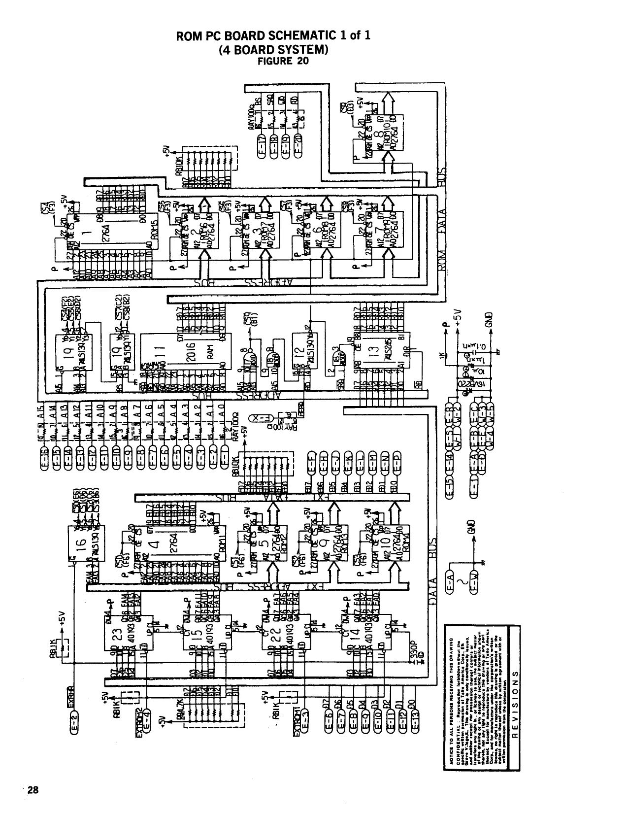
ROM PC BOARD SCHEMATIC 1 of 1
(5 BOARD SYSTEM)
GAME BOARD COMPONENT LAYOUT (4 and 5 BOARD SYSTEMS)
(e} ooooooooocoec]s eooooooooocoeos,s uy a =< Eth a
~N
a Z| fo] a >| if) c|
GAME BOARD FOUR AND FIVE BOARD SYSTEMS
DESCRIPTION GAME PCB 26-00001-018 |IC SOCKET 18P. 29-00001-008 | DIP SWITCH 8 P 99-C0500011A] CONNECTOR 12 PIN 99-CO50551A |CONNECTOR 30 PIN 1S1___ |26-00001-028 |IC SOCKET 28P SOP |25-00001-101 [CONNECTOR RT. ANG. 50 P. 1$2__[26-00001-024 [IC SOCKET 24P |
| Is3 | 26-00001-040 |IC SOCKET 40P | | | |
| 184 | __[26-00001-020 [IC SOCKET 20P. | | | |
| P | 99-C0600403A] TEST POINT | | | |
| 12_ | [IcB | STAND-OFF | | |
13 [TRI _ [99-A0100012A] TRANSISTOR 250423 14 _[TR7 __ [99-A0100143A] TRANSISTOR 250635 15 OP! _ [15-53900-001 |LM3900 16 [0P2 _ |99-B17Z0333A| POWER AMP MB3730 17_[Ici___[15-30016-001 [7416 15-30017-001 |7417 15-10003-001 | RAM 2114-2 15-60006-001 | SOUND IC AY-8910 99-B11J0002A| TTL RAM 93410 15-20000-001 }74LS00 15-20002-001 |74LS02 15-20004-001 |74LS04 15-20008-001 |74LS08 99-B01A0032A] 74LS32 (TI ONLY) 15-20074-001 | 74LS74 15-20096-001 |74LS96 NOT USED 15-20138-001 |74LS138 15-20153-001 | 7415153 32_[IC16 _ [15-20155-001 |74LS155 33_ici7__ [15-20253-001 [7418253 34_fici8 _|15-20257-001 [7418257
| 35 | fICi9 | _|15-20259-001 [7418259 |
36_[ic20__|15-20174-001 [7418174 (37_[iC21__[15-20367-001 |74LS367 38 15-20374-001 | 7418374 39 15-20393-001 [741393 99-BO7C0584A| CMOS MB14584 15-30004-001 |7404 15-30367-001 |74367 15-50555-001 | Timer 555 15-30074-001 |7474 15-30273-001 [74273
- [15-00015-001 [CPU 2-80A |
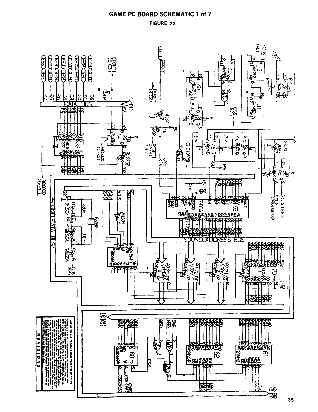
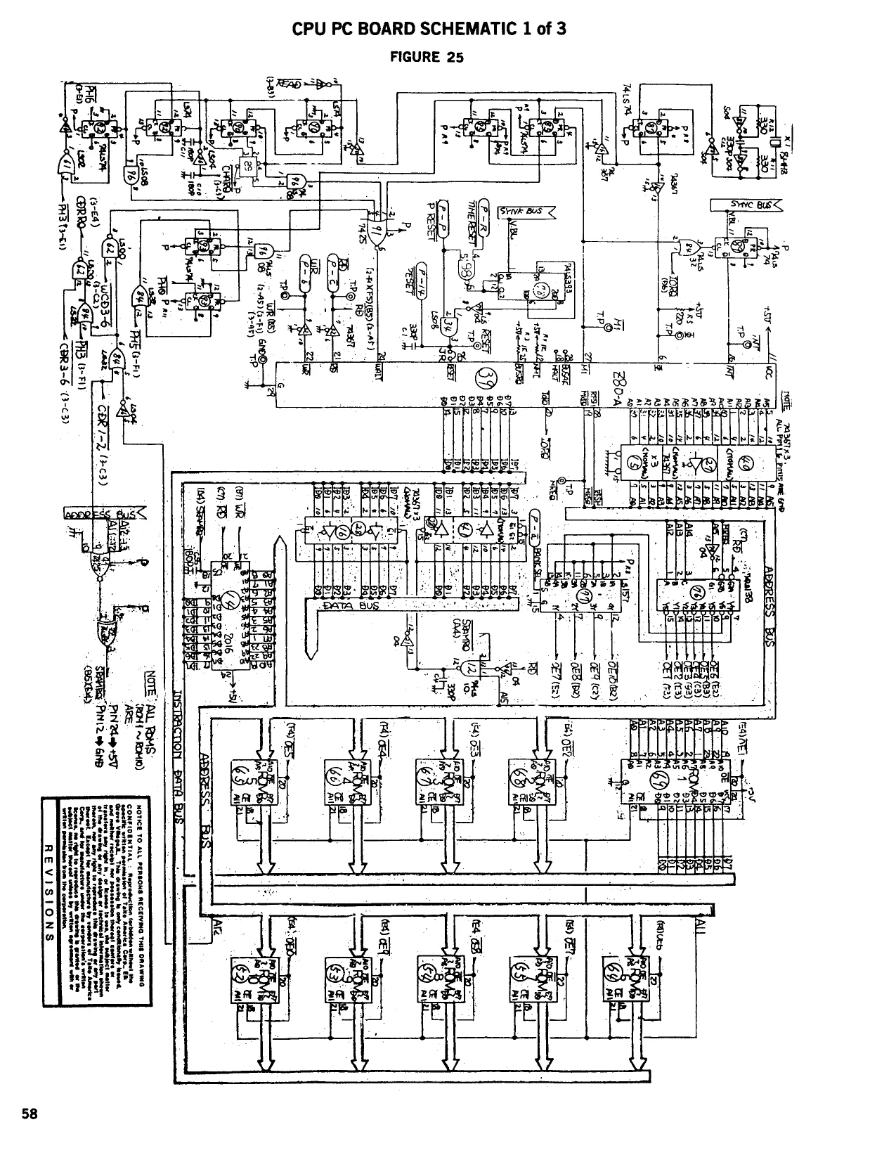
This page reads as a drawing: its text was drawn rather than typeset, and comes out in fragments. See the original scan.
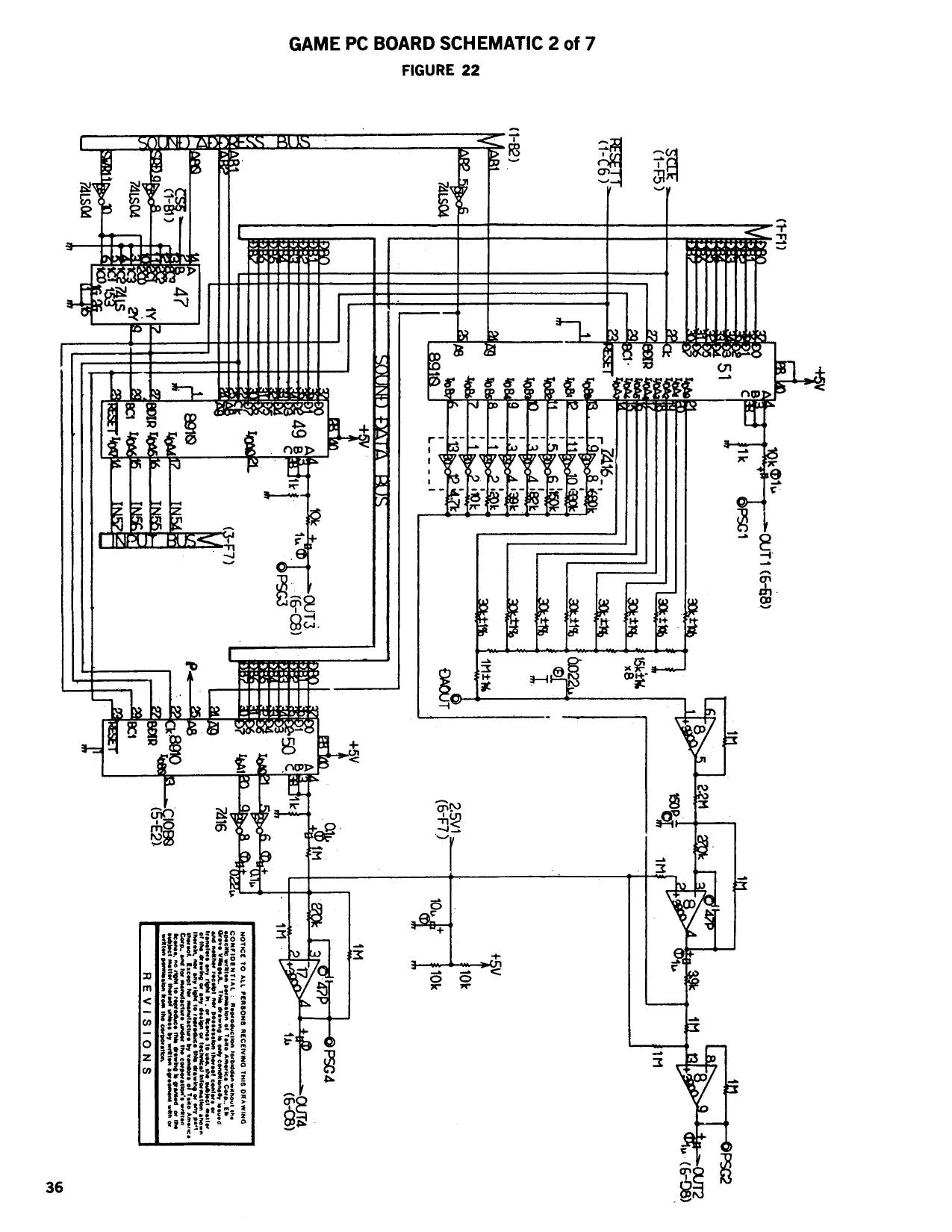
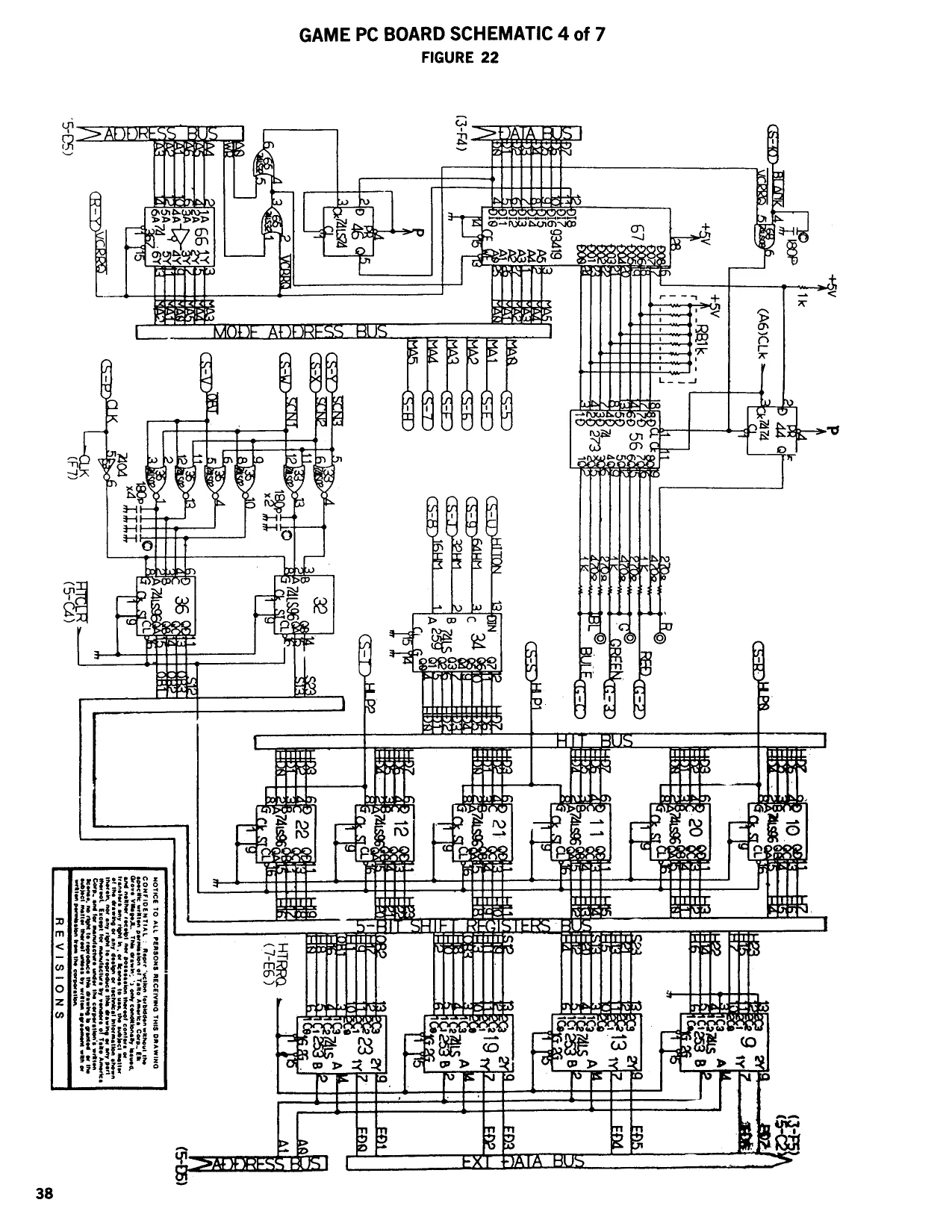
This page is a drawing, shown as the original scan.
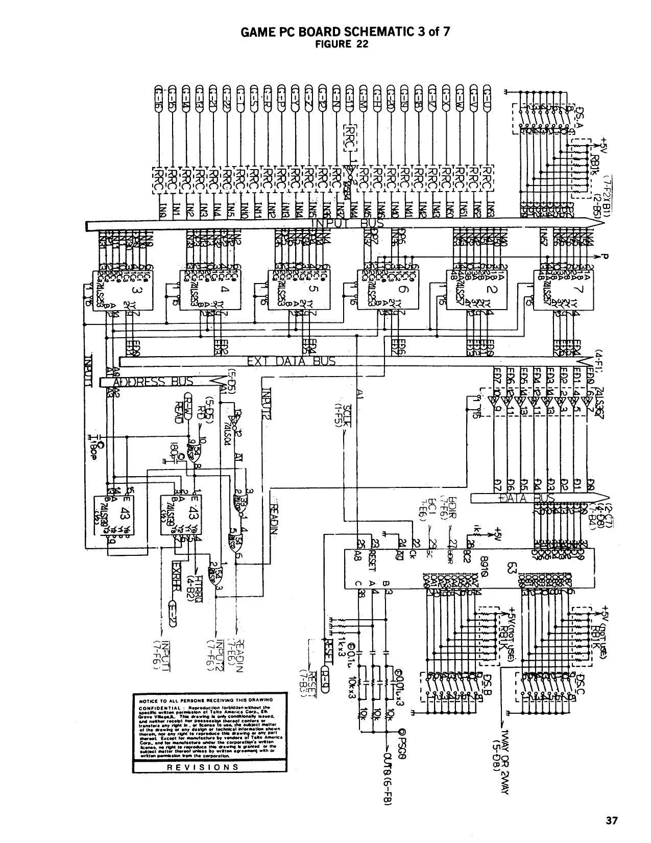
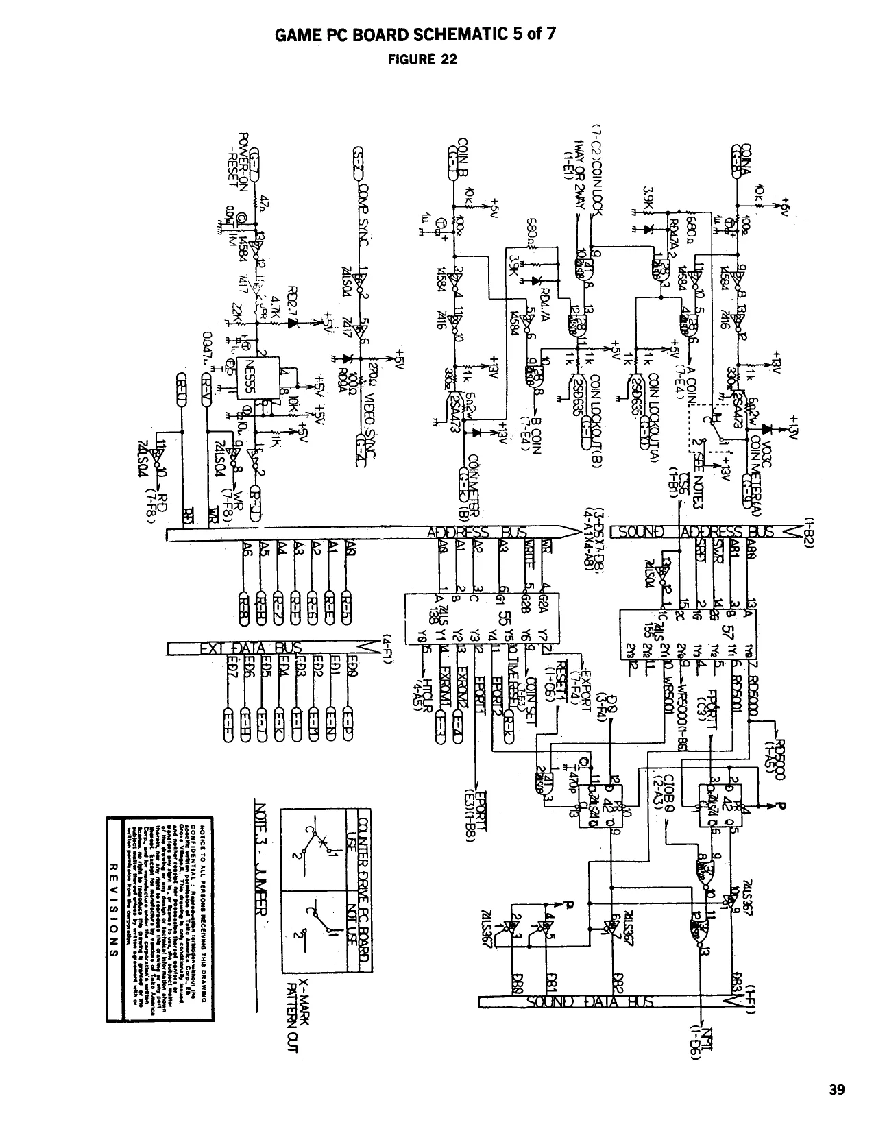
This page is a drawing, shown as the original scan.
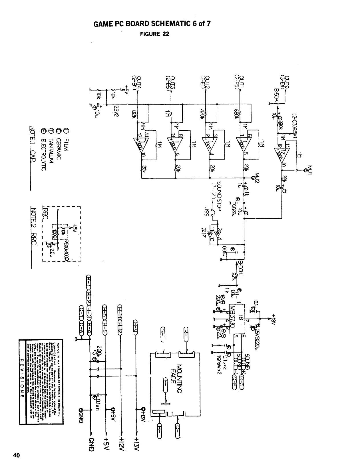
This page is a drawing, shown as the original scan.
This page is a drawing, shown as the original scan.
This page is a drawing, shown as the original scan.
This page is a drawing, shown as the original scan.
(9Q-S)
STE ICING CES er ral tea-ginievay 8 sG-£) 108 Flog (eG) a8 ot WCa =D gE Sy NICO 193-5) (28-7) TRAULH NIOOV (9-5) (28-2) ZL 0GiN I ve
—~1a0dx3 (PGS) (@v-2) LIAdNI
REVISIONS WOTICE TO ALL PEREONS RECEIVING THIS DRAWING ee 4 = Gau(sy-S) aMicv-S)
AS+ AS+
GAME PC BOARD SCHEMATIC 7 of 7
ere ence ee caeeey (NETeTT eqeegge Geeag aye eiaeiee Gen aeeR hegnageds Gecegal eeceeeg ai euneiy
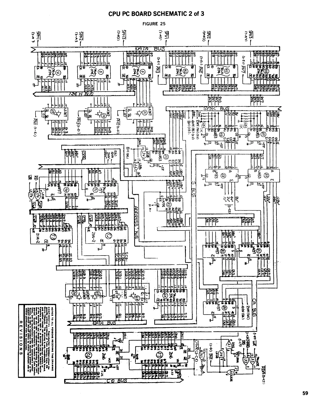
This page reads as a drawing: its text was drawn rather than typeset, and comes out in fragments. See the original scan.
This page is a drawing, shown as the original scan.
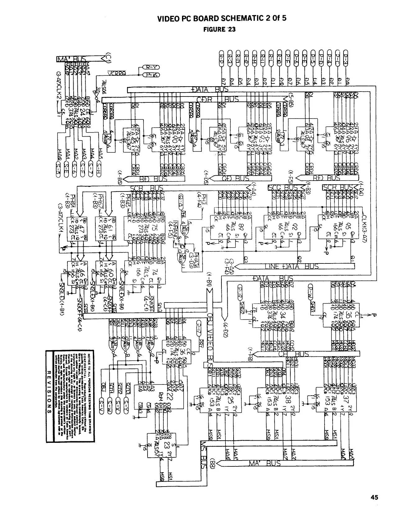
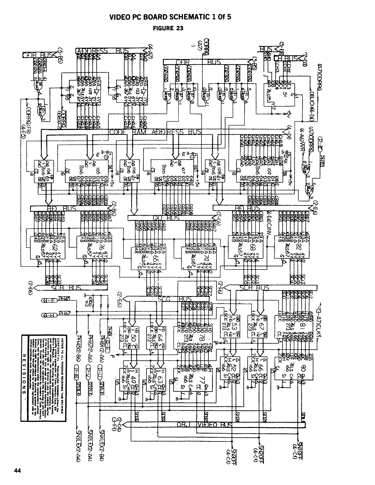
This page is a drawing, shown as the original scan.
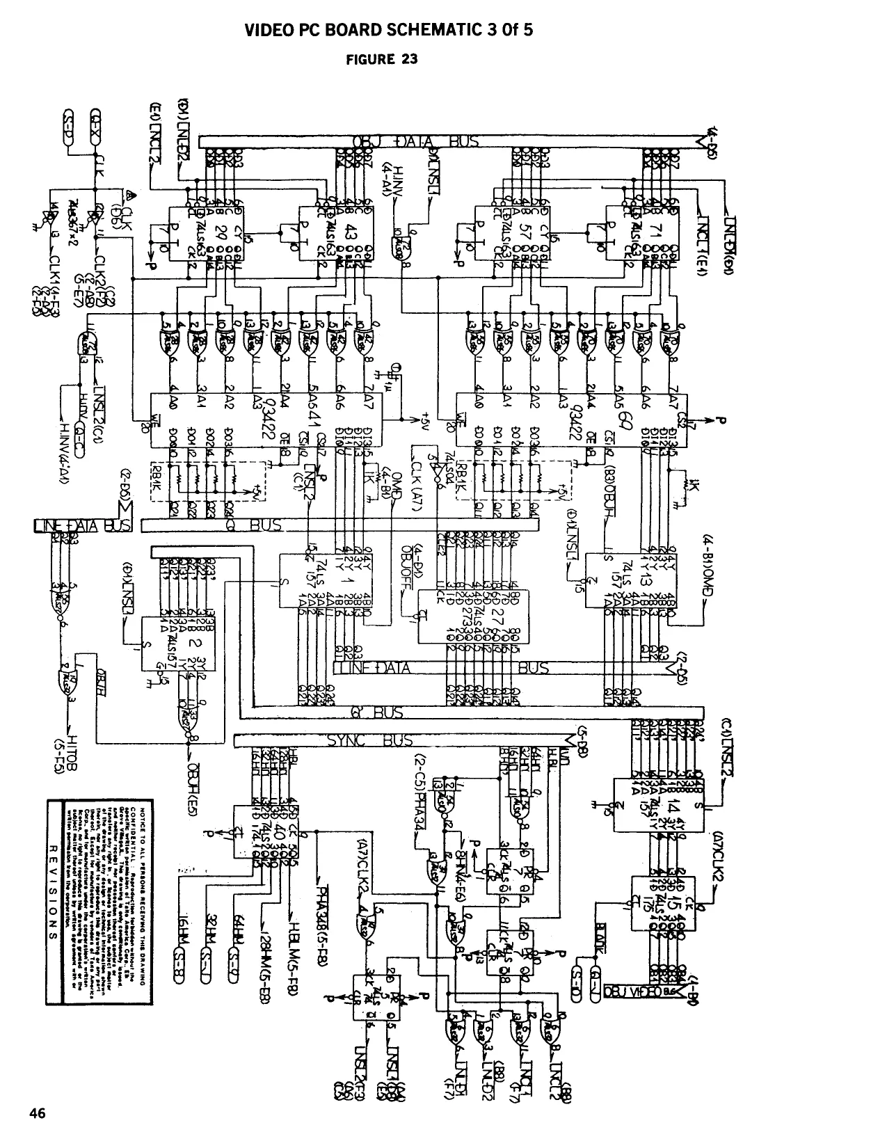
This page is a drawing, shown as the original scan.
VIDEO PC BOARD SCHEMATIC 4 Of 5
CINVO=ES) ey A TALS, A 574% ele
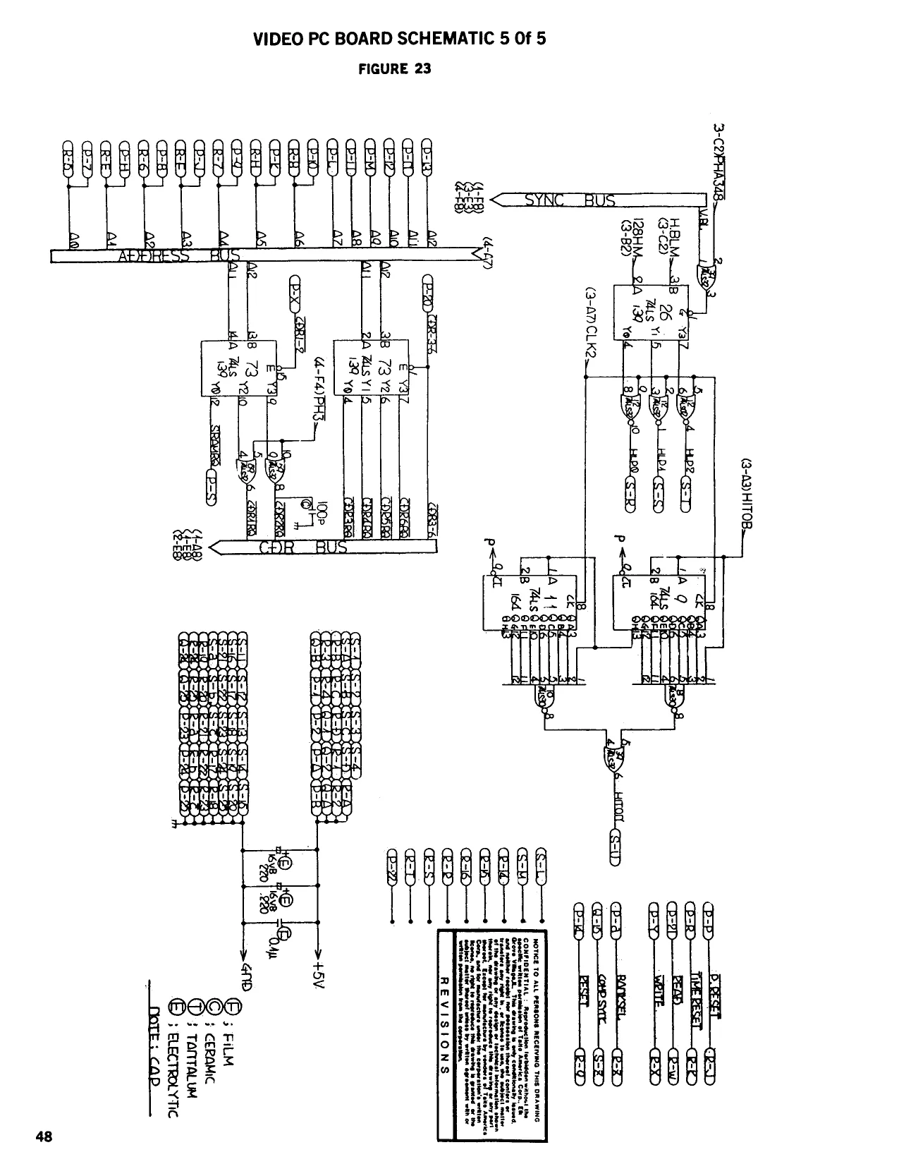
This page is a drawing, shown as the original scan.
CPU BOARD COMPONENT LAYOUT (4 BOARD SYSTEM)
3 7] ‘aaa Uiabadoas! rhe Fa ibaa. a
iA ne 5 soli oie ey on Hades 7 A bases 0 : i; Ae a” ! I S paadaa ¢ 5 dbom = ata
ELECTROLYTIC
«9 "ae DSBs died Baie BBE Sie
- . k— ose
TANTALUM
a be MARK <= _ CERAMIC
This page reads as a drawing: its text was drawn rather than typeset, and comes out in fragments. See the original scan.
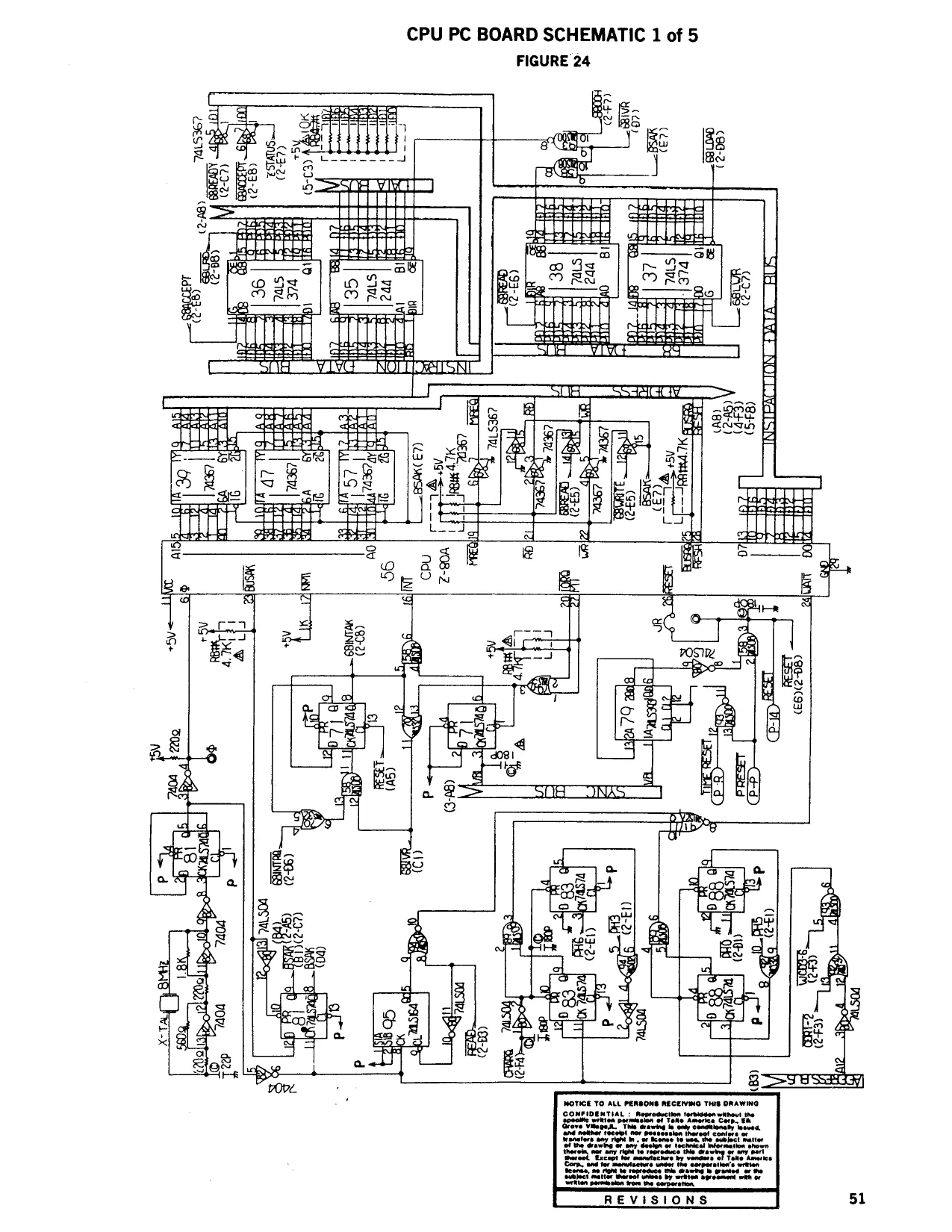
This page is a drawing, shown as the original scan.
This page is a drawing, shown as the original scan.
This page is a drawing, shown as the original scan.
This page is a drawing, shown as the original scan.
This page is a drawing, shown as the original scan.
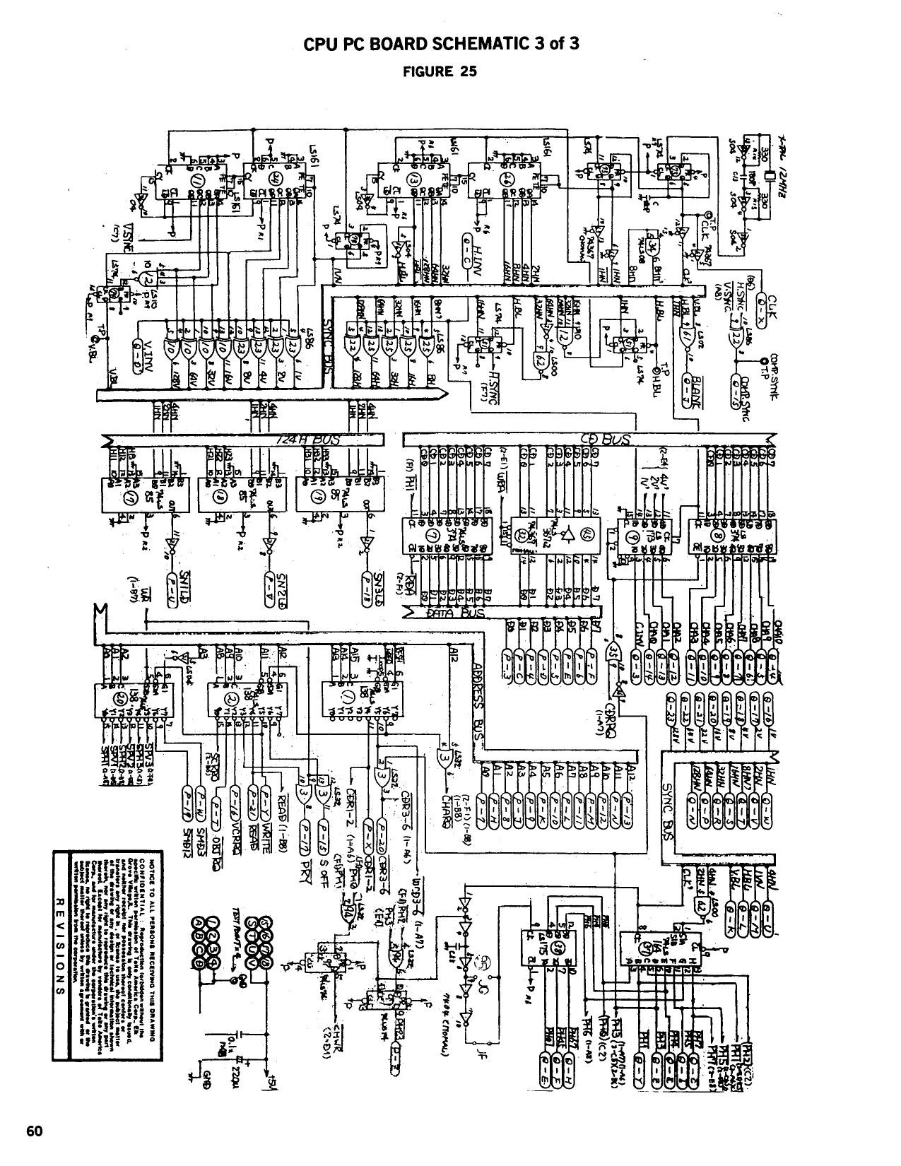
This page reads as a drawing: its text was drawn rather than typeset, and comes out in fragments. See the original scan.
This page carries no recoverable text. It is a drawing or a photograph. See the original scan.
This page is a drawing, shown as the original scan.
This page is a drawing, shown as the original scan.
This page is a drawing, shown as the original scan.
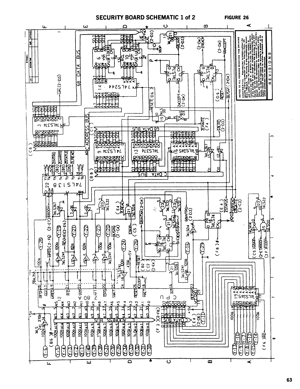
This page reads as a drawing: its text was drawn rather than typeset, and comes out in fragments. See the original scan.
SECURITY BOARD FIVE BOARD SYSTEM
TAITO | iteM |PARTNO. _| DESCRIPTION 1____|15-26000-001 /4isoo 2___ |15-20004-001 |74LS04 3___|15-20008-001 [741808 4____[15-20032-001 [741832 5 ___|15-20074-001 [741874 6 __ |15-20138-001 |741s138 7___ |15-20139-001 [7418139 8 __|15-20191-001 |74LS191 9 _|15-20241-001 [7418241 10 __|15-20244-001 [74LS244 11 [15-20245-001 [7418245 12___ [15-20367-001 [741367 13 __|15-20374-001 [7418374 14 |15-00015-001 [CPU Z80A 15 [16-00016-003/ROM BA3-11 16 ___|99-A1200233A|CAP DISC 33PF 50V 17____ |99-A1200251A| CAP DISC 180PF 50V 18 |99-A1200257A| CAP DISC 330PF 50V 19 __|99-A1200317A] CAP DISC .1UF 50V 20 __|99-A1320519A| CAP TANT 10UF 25V 21 ___|99-A1000135A|CAP ELEC 220UF 16V 22 |26-00001-028 JIC SOCKET 28 PIN 23 |26-00001-040 [iC SOCKET 40 PIN 24 XTAL 3.0 MHZ 25 RES DIP 100 OHM
This page is a drawing, shown as the original scan.
This page is a drawing, shown as the original scan.
“*! y20 vac From 3 SECONDARY BRACKET
ERO # 41-0600 Wales _RP [Al 7-uwes RP |
‘SPEAKER fe 68 ve [mo FRR secoWOARY PRIMARY BRACKET sence
- SR MARQUEE LighTS
INSTRUCTION LIGNTS.
end aco 0 woe caw va SYNC Var Avo + wa
Reser ven
co gw mK va
“Top cow core RE com coc a Bee serves 6w 1p COIN DOOR ra * vows!
Rew Leer
FIRE Riss sume RIS-2, (él ao nea vingo sxire} ad VIDEO BLUE RIS-5 Ree nuo0 ~ Riso RS Re-12 Cow sui cere rust Botrem COW CNTR. oo Power Sureiy Pee LEFT cow Lock “ Ge Goxor-051 { oven
- ‘RI6~) ’ &
Ri6-3 Ree RS oxo Rue '
Rie-7 wast Ree Rica R6-10
ve wa VES WIES VEE ve?
| ven | i | 1 | |||
| ve | ! | 1 Piss TRawsisToR | |||
| FITER | t | | MEAT sin Rosy, | TAITO AMERIGA CORPORATION | ||
| FILTER BOARD | — | i | i | ' | |
| (8-00120~-201 | w | our | aac | Kaeser | i |
| vee | pre | ar | woe | --- 5-7 eo |
+ + aa a ‘OR ACTH RI Pe} — fo] ELEVATOR ACTION WIRING DIAGRAM TYPICAL 27 PLACES =
WARRANTY
TAITO AMERICA CORPORATION warrants that its printed circuit boards and parts are free from defects in material and workmanship under nomal use and service for a period of ninety (90) days from the date of shipment. Seller warrants that its monitors are free from defects in material and workmanship under normal use for a period of thirty (30) days from the date of shipment. The factory also warrants all socketed parts for a period of ninety (90) days when furnished with the game serial number. If the above products fail to conform to this Warranty Taito America Corporation has the option to repair, replace, or credit the Buyer's account. The Buyer must notify Taito America Corporation in writing upon finding the defective product. Buyer must also return the defective product prepaid to Taito America Corporation’s factory located in Elk Grove Village, Illinois. If Taito America Corporation determines upon examining the returned product that damage was caused by accident, misuse, neglect, modification, or improper repair or testing, this Warranty will be void. Inno event will Taito America Corporation be held for loss of profits to Buyer.
\rarro/ TAITO AMERICA CORPORATION 1256 Estes Avenue, Elk Grove Village, IL 60007 Telephone (312) 981-1000 Telex 25-3290