Red Baron DP-169-1st-02B
Red Baron (revised hardware) (Atari, 1980) · Drawing Package · 1 pages · original scan
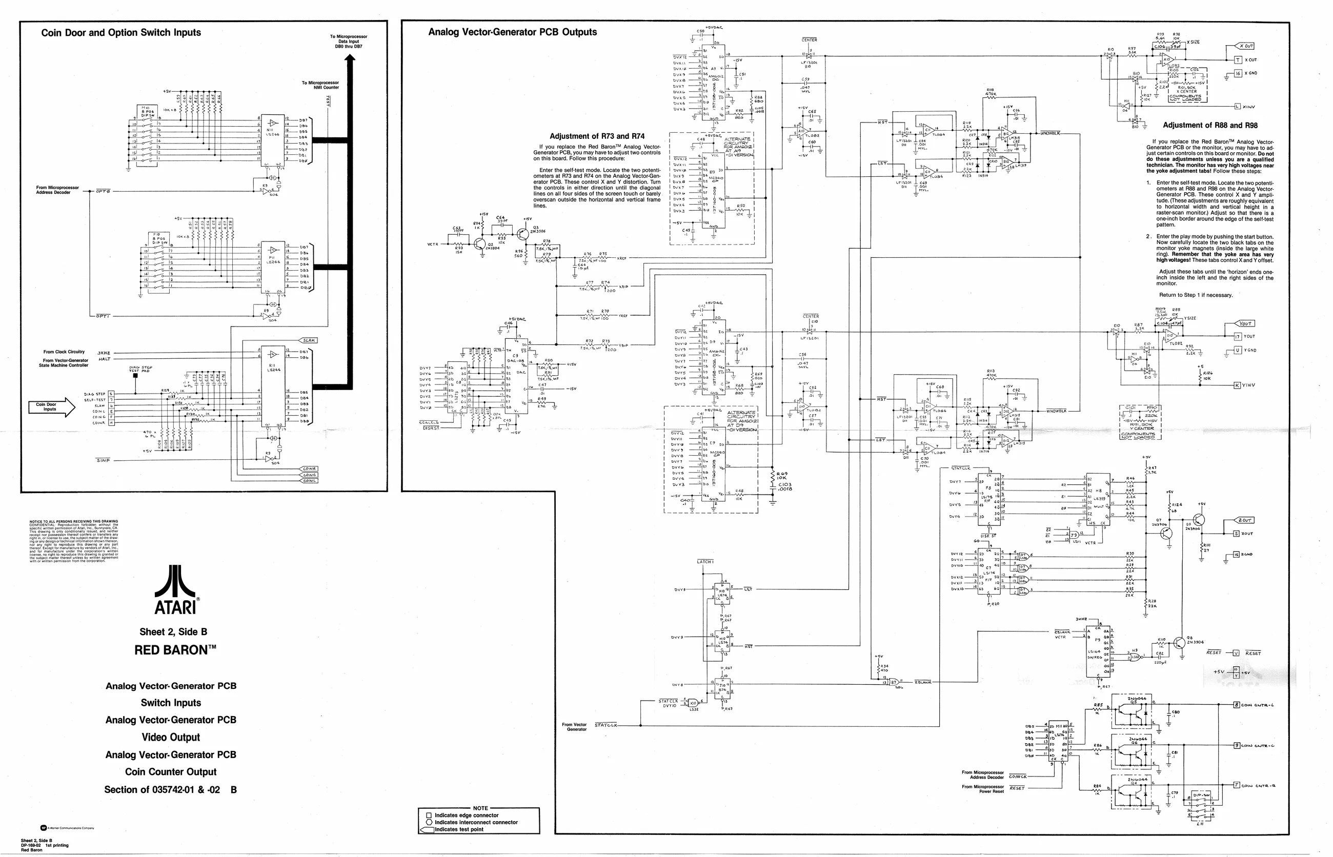
Coin Door and Option Switch Inputs
Analog Vector-Generator PCB Outputs
Adjustment of R88 and R98 Adjustment of R73 and R74 It you replace the Red Baron" Analog Vector- Generator PCB, you may have to adjust two controls fn this board. Follow this procedure: If you replace the Red Baron™ Analog Vector- Gonerator PCB or the monitor, you may have to ad-
just certain controls on this board or monitor. Do not
do these adjustments unless you are a qualified
technician. The monitor has very high voltages near
the yoke adjustment tabs! Follow these steps:
‘mode. Locate the two potent!
- Entor the selttest mode. Locate the two potent Te ‘omters at REB and ROG onthe Analog Vector. L Generator PCB. These control X and Y ampll tude. (These adjustments are roughly equivalent to horizontal width and. vertical height in a fasterscan monitor) Adjust 80 that thee Is & {neinch border around the edge ofthe slttest patter ‘controls in either direction until the diagonal lines on all four sides of the screen touch or barely ‘overscan outside the horizontal and vertical frame
Enter the play mode by pushing the start button. ‘Now caretully locate the two black tabs on the ‘monitor yoke magnets (inside the large white ting). Remember that the yoke area has. very high voltages! These tabs control Xand ¥ offset. ‘Adjust these tabs until the ‘horizon’ ends one- Inch inside the left and the right sides of the monitor.
Return to Step 1 if necessary
Sheet 2, Side B
RED BARON™ ihe QL) B08 ae cd
+5v =F) er Analog Vector-Generator PCB wo —— ae Switch Inputs [: ire HU OP, t—fBcon extant Analog Vector-Generator PCB fesiveisr. SAVED Som Video Output Analog Vector- Generator PCB Coin Counter Output
Section of 035742-01&-02 B