Thunder Blade
Thunder Blade (upright) (FD1094 317-0056) (Sega, 1987) · Manual · 46 pages · 27 sections · original scan
1ST—PRINTING-MR Ro Ro Ko Ko Ko Ko Ko Ko KK KH Ko Kr Ho Ko Ho Ho Ho Ho HH Ho KH HK KKK Kr Ko Ko KB’
SEGA
‘| Uoocaaleerr Hilal
ECONOMY UPRIGHT TYPE I]
OWNER’S MANUAL
SEGA ENTERPRISES,LTD.
BPPPLL PLE PLL PER LPP LER LEPREPPPEPR PREP Ro Rs Ro RoR KM Mr KK Hoe Ko Ko Koh Ko KH Ro KK Ko KM Ko Ko KH Ko MH Mo KK Ko KH HH MoH HM HM HMM BEPLLOPL EEL EE EEPEEE PEPPER EREPEPREPRPPPPPPREPEREEREP
MANUAL NO, 420-5876-01
ee
This page carries no recoverable text. It is a drawing or a photograph. See the original scan.
10.
11.
12.
13.
14. TABLE OF CONTENTS
INTRODUCTION OF THE OWNER’S MANUAL (srvveresssssseserstssrsetseeteereetseeees 1
HANDLING PRECAUTIONS ovvrssessessesse+sesessessessesseseesessesseesssrescereneesveneeresneens 1
PREVENTION OF COUNTERFEITING AND CONVERSION (vvrvrrssssssesteesees 2
PRECAUTIONS CONCERNING THE OF INSTALLATION 3
NAME OF PARTS'@ aexisscicesrnnie nano nmarammm neces 4
NAMES GF BARRIS G) s+0s0veoscsssnccssncussenccoosvassconscsascrvosascssesnsenenesanestisesiwesesats 5
SERVICE SWITCH FUNCTIONS — -v++e+sse+sessessesssessesseeseessucsssssesseseeeeseesneseeensens 6
Ic BOARD Ave eee ee en ee eeeeeeeeeeer arenes Ceeneneneeeeeereeeeeeeeeene sen ene ene eeeeereeseeeeeeeeseneeeneeeeeenes 7
OPENING THE CONTROL UNIT AND ADJUSTMENT vvvvvrssressssesseserstresersees 8-9
REPLACING THE MOTOR BRUSHES (evvssssssssssssseeseeseseeeseeeneeeeeaeeeeeeeneaeeeeee ees 10
5p INGH MONROE) <e.cessnrvsassiasmrenermcceimanrsiekrnararmcncimoumanasenonentiess u
DIP SWITCH SETTING —vvvvesesessesesessesseseesecsesuesesseeeenescesesssessensansnesaneansanaes 12
EPROM/MASK ROM LOCATIONS | s+sss:+se+se+ss+e+eesseessesessseeeseeeeesserssenseenseeses 13
SHLP —TEST neiesnsiia mine ccong Ere R URES 14~18
PARTS LIST Pereerrrr rir er terrererrreer er rer terre ere errr eee rere errr errr etree ere etree eee tree trees 19~ 36
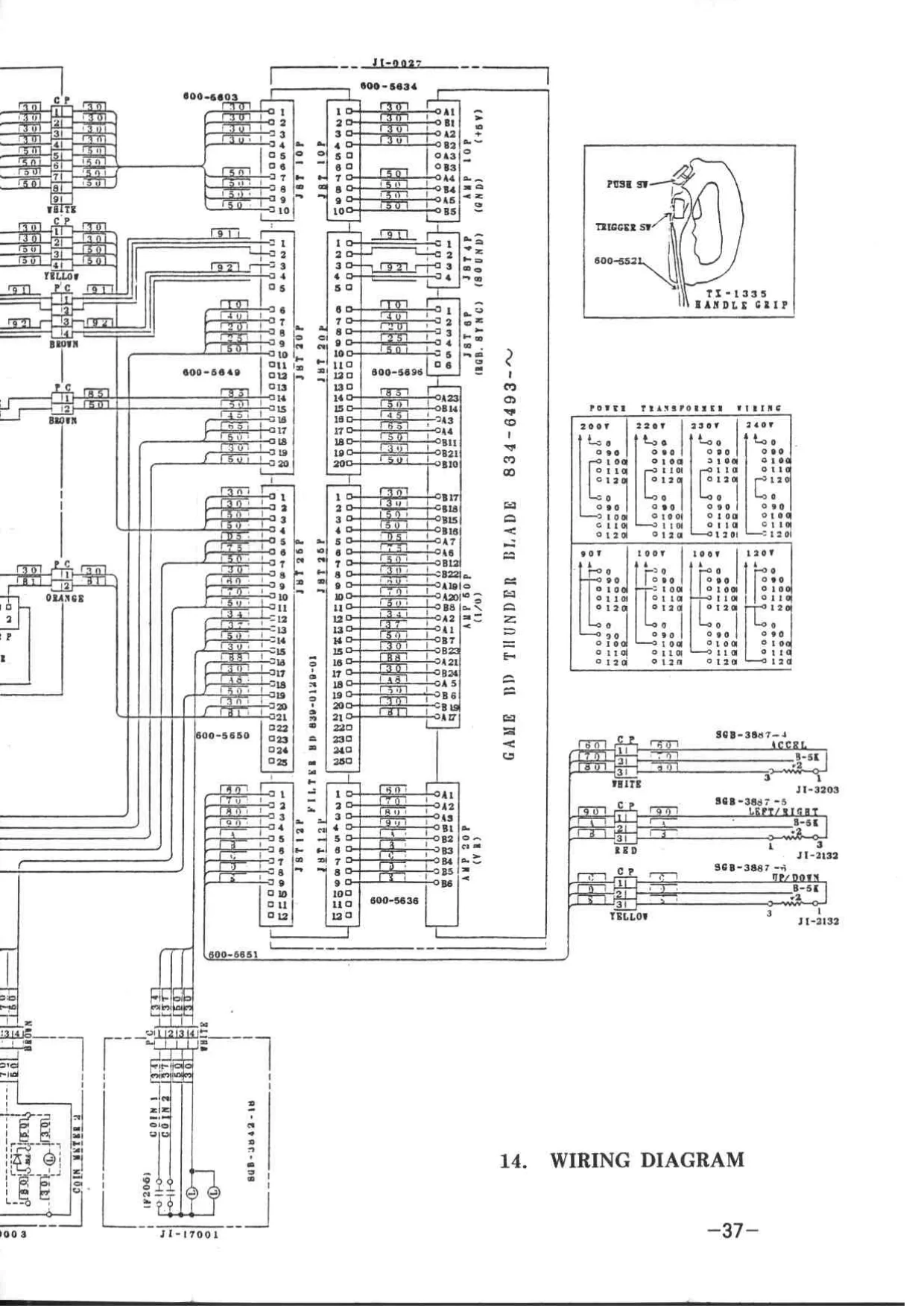
WIRING DIAGRAM, | :<s«evecscssveemsccccasemin caer sanncisecenunriesesriecentsenaneavinclonecseny 37
SPECIFICATIONS
INSTALLATION SPACE : 700 mm (27.6in.) W x 550 mm (21.6in.) D HEIGHT 1650 mm (65. Oin. ) POWER : 180W C.R.T. : 20” MONITOR WEIGHT : 110 kg. (242.5 Ibs.)
© Descriptions herein contained may be subject to improvement
changes without notice.
This page carries no recoverable text. It is a drawing or a photograph. See the original scan.
INTRODUCTION OF THE OWNER’S MANUAL
SEGA ENTERPRISES, LTD., supported by its high electronic technology of LSIs, microprocessors, etc. and a wealth of experience, has for more than 30 years been supplying various innovative and popular game machines to the world market. This OWNER'S manual is intended to provide detailed comments together with all the necessary information covering the operation in general of electronic assemblies, electromechanicals servicing control, spare parts, etc. as regards the THUNDER BLADE ECONOMY UPRIGHT I a new SEGA product. The manual is intended for those who have knowledge of electricity and technical expertise especially in
ICs, CRTs, microprocessors, etc. Carefully read so as to acquire sufficient knowledge before working on the machine. Should there be a malfunction, nontechnical personnel should under no
circumstance touch the interior system.
- HANDLING PRECAUTIONS
When installing or inspecting, be very careful of the following points and pay attention to ensure that the player can enjoy the game safely.
o Be sure to turn the power off before working on the machine. o To insert or pull out the plug quickly is dangerous. o It is necessary to make sure that the power cord or the
grounding wire is not exposed on the road, etc. in a manner so as to be dangerous. Make sure that grounding connections are made safely at the position where so specified. o Do not use any fuse that does not meet the specified rating. o Make complete connections for the IC board and other connecters. Insufficient insertion is very dangerous.
Also, for the IC board circuit inspections, only the logic
tone is allowed. The use of a tester is not permitted, so be
careful in this regard. After confirming that there are no irregularities, turn the power ON.
- PREVENTION OF COUNTERFEITING AND CONVERSION
LABELLING To prevent counterfeits and conversions, the following labels are put on all the SEGA products. When handling such
goods, be sure to confirm the labels. They are used to prevent illegal acts such as the unauthorized copying of the products and the printed circuit boards thereof or carrying on business by manufacturing similar merchandise or by converting, selling or using such products or printed
circuit boards.
ORIGINAL SEAL LICENSE SEAL
The following seal is put on The following seal is put on the the machines manufactured by kits, such as the printed SEGA. circuit boards, of SEGA
products.
“
ar
i inant shee ee de eee eee
q a2 q
COPYRIGHT NOTICE
This SEGA product has the copyright notice as follows:
© SEGA 1987
This signifies that this work was disclosed in 1987 and is the property of SEGA ENTERPRISES, LTD.
3.
PRECAUTIONS CONCERNING THE PLACE OF INSTALLATION
The THUNDER BLADE ECONOMY UPRIGHT [| is an indoor game machine.
Absolutely donot install it outside. Even indoors, avoid installing in places mentioned below so as to ensure proper
usage: Places subject to rain or water leakage, or condensation due to humidity. o In the proximity of an indoor swimming pool and/or shower. o Places subject to direct sunlight. o Places subject to heat sources from heating units, etc., or hot air.
Vicinity of highly inflammable/volatile chemicals or hazardous matter.
o Sloped surfaces. © Vicinity of antidisaster facilities such us fire exits and fire extinguishers. o Places subject to any type of violent impact. o Dusty places.
- NAME OF PARTS (@
faethe tele aay,
20” MONITOR 2
200-5095
FRONT GLASS _~ JI-1702
CONTROL UNIT _~ JI—20002
TOOLS Y
(TAMPERPROOF WRENCH) (TAMPERPROOF WRENCH )
M4 540-0006-—01 M4 540-0018 M5 540-0007-01 M5 540-0017 M6 540—0015—01
NAME OF PARTS (2)
GAME BOARD
834—6493-—03
Sw UNIT
TX—1624
/ SHIELD PLATE [ SHIELD CASE TX-—0028 TX-—0027
VA y, ASSY POWER SPLY /
J1—40003
- SERVICE SWITCH FUNCTIONS
The layout as shown below can be viewed by opening the coin chute door.
COIN CHUTE DOOR
INSTRUCTIONS
- DEMAGNETIZING SWITCH ...----
@ SERVICE SWITCH ......+-.0005
@ TEST SWITCH ......-..-000-- r
@ VOLUME ADJUSTMENT +++" °*" 7"
@® CIRCUIT PROTECTOR --+++++++-- @ VOLUME ADJUSTMENT
©) CIRCUIT PROTECTOR
@ SERVICE SWITCH
/@ TEST SWITCH
@ DEMAGNETIZING SWITCH
- CASHBOX
Used for removing the on-screen
color uneveness. Used for the purpose of
servicing and increasing the credits without registering on the meter (this allows you to
check the game). For operating this switch, see SELF-TESTING. The volume of the speaker inside the cowl can be adjusted.
When the motor is overloaded, the
breaker functions, causing the motor which is connected with the handle, to stop. To restart it, push the projecting portion of the CIRCUIT
PROTECTOR.
- IC BOARD
Open the back door of the cabinet, pull on the 18 NYLACHes and take off the shield plate to perform game board maintenance.
\ NYLACH / \ SHIELD PLATE
FOR SOUND 4P INPUT I/O 50P
5V, GND 10P TO CONTROL UNIT 20P
R.G.B. 6P
- OPENING THE CONTROL UNIT AND ADJUSTMENT
- OPENING THE CONTROL UNIT
© When opening the CONTROL UNIT, take off the 4 TAMPERPROOF SCREWS (J) open the COIN CHUTE DOOR, take off the 2 SCREWS @ and the entire CONTROL UNIT will open towards you.
TAMPER PROOF SCREW (D
tf fF
& & SCREW @ i=)
2, HANDLE & THROTTLE UNIT ADJUSTMENT
In the test mode, cause the DIAGNOSTIC
DIAGNOSTIC INPUT DISPLAY to INPUT TEST
qppeat ph ehersereds COIN #1 OFF START OFF
(to select it, push the test COIN #2 OFF SERVICE OFF switch and move the handle VALCAN OFF upward and downward). MISSILE OFF
STICK RIGHT LEFT 80H ® STICK UP DOWN 80H SPEED 80H ~ v4)
Say
@ To make VR adjustments in a horizontal direction
(RIGHT/LEFT), release the VR."A" bracket's "A" screws and turn gear "A" in a manner so that when the handle grip is in an unoperated status, 80H+2H is obtained. At this time, also make backlash adjustments.
- When making vertical (UP/DOWN) adjustments, while maintaining the present inclination of the handle unit, unfasten the gear "C" bracket's "B" screws and fasten the gear "C"
bracket when the monitor display shows 80H+2H. For backlash adjustments, loosen the VR "B" bracket.
GEAR “A” VR “B"
SCREW “
j GEAR “C"
VR‘A"
__ GEAR “B"
SCREW “B”
@ SPEED
Unfasten the 2 adjustment screws to loosen the volume bracket, making sure that in relation to the gear engagement, the variable value in the test mode is within the allowable adjustment range, and then refasten the adjustment screws.
GEAR A
- REPLACING THE MOTOR BRUSHES
y, CONTROL UNIT
MOTOR®
To replace the motor brushes, release the cap with a screwdriver, etc. and take out the brushes. Replacement once every 6 months is recommended. Make sure that both brushes are
simultaneously replaced. CAP
ae ee a 601-5929 5929 aa” meat \ 2 350-5113
- 20 INCH MONITOR
@ V.HOLD
@ V.SIZE
@) V. POSITION
@ H.HOLD
® H. SIZE
© H. POSITION
@ BRIGHT
® B.GAIN
@ G.GAIN
q R. GAIN
10.
DIP SWITCH SETTING
COIN/CREDIT OPTION SWITCH SETTING DIP SWA
| OPTION | t[z[3:[«[s[e«|[7 | [es | COIN SW1 | COIN SW2 |
| 1 | 1 cREDIT | OFF |oFF |orF | orF |orF | OFF |orr OFF | / |
1 2GREoITS | ON |oFF JOFF|OFF|ON | OFF | oFF |OFF 1c 3creoits | orF}on Jorr|orr|orr|oNn |orr |orF 1 4creoits | ON Jon lorr|OrF\ON JON |oFF |OFF : SCREDITS | OFF]OFF|ON |oFF\OFF| OFF |ON |OFF 1 6cReDITS | ON |oFF Jon |orF|ON |oFF|ON |OFF 2 ycreoit | oFF|on Jon |orr]orF}on lon |orr 3 1creoit | on |on Jon |orr}on Jon Jon |orF ‘ 1creoit | orelorr lorr|on |ore| ore |orr |on 2 acrepits | on |orF jorr}on [on | oFF |orF lon ? 7 CREDIT 4 2: CREDITS ‘ FCREDITS | ofF}on JorF lon |orF|oNn |orr Jon 6 4 CREDITS 2 1 CREDIT Z SCREDIT | on Jon Jorr}on Jon Jon |orr on 1 1 CREDIT 2 2 CREDITS acoins 3creoits | orr|orr|on Jon |orr]orr lon Jon 4COINS 4 CREDITS SCOINS 6 CREDITS 1 COIN 1 CREDIT 2COINS 2 CREDITS ZcOINS 7 CREDITS | on |orF lon Jon Jon |orF}oN JON 4 COINS 5 CREDITS TCOIN 1 CREDIT ycoww — S CREDIT | orrlon Jon [on |oFF]ON JON Jon
| FREE PLAY | on [on [on Jon [on [on | on |
COIN SW #1 COIN SW #2
GAME OPTION SWITCH SETTING
DIP sw B
| cern | —__T | rae |
Z CABINET JECONOMY|
| Type | juan | ON | L_J |
| ROVERTISE | OFF | [orF] |
| SOUND | ON | [on] |
TIME 30 SEC OFF TiME_0 SEC On i OFF | OFF
| aeen | 7 | ‘OFF [ON | ||
| Fine | —s | on [OFF | Saee | Lu |
% ON | ON CONTINUE NOT CONTINU! NORMAL
| GAME | EASY | DIP Sw | |
| orrricuty [HARD] | 5 | B | A |
| HAROEST | Oo | oo |
Sea 1 J
- The above TIME 30 SEC signifies that the allotted number of player’s helicopters does not decrease regardless of how many are lost within said 30 second period.
10.
DIP SWITCH SETTING
COIN/CREDIT OPTION SWITCH SETTING DIP SWA
| OPTION | t[z[3:[«[s[e«|[7 | [es | COIN SW1 | COIN SW2 |
| 1 | 1 cREDIT | OFF |oFF |orF | orF |orF | OFF |orr OFF | / |
1 2GREoITS | ON |oFF JOFF|OFF|ON | OFF | oFF |OFF 1c 3creoits | orF}on Jorr|orr|orr|oNn |orr |orF 1 4creoits | ON Jon lorr|OrF\ON JON |oFF |OFF : SCREDITS | OFF]OFF|ON |oFF\OFF| OFF |ON |OFF 1 6cReDITS | ON |oFF Jon |orF|ON |oFF|ON |OFF 2 ycreoit | oFF|on Jon |orr]orF}on lon |orr 3 1creoit | on |on Jon |orr}on Jon Jon |orF ‘ 1creoit | orelorr lorr|on |ore| ore |orr |on 2 acrepits | on |orF jorr}on [on | oFF |orF lon ? 7 CREDIT 4 2: CREDITS ‘ FCREDITS | ofF}on JorF lon |orF|oNn |orr Jon 6 4 CREDITS 2 1 CREDIT Z SCREDIT | on Jon Jorr}on Jon Jon |orr on 1 1 CREDIT 2 2 CREDITS acoins 3creoits | orr|orr|on Jon |orr]orr lon Jon 4COINS 4 CREDITS SCOINS 6 CREDITS 1 COIN 1 CREDIT 2COINS 2 CREDITS ZcOINS 7 CREDITS | on |orF lon Jon Jon |orF}oN JON 4 COINS 5 CREDITS TCOIN 1 CREDIT ycoww — S CREDIT | orrlon Jon [on |oFF]ON JON Jon
| FREE PLAY | on [on [on Jon [on [on | on |
COIN SW #1 COIN SW #2
GAME OPTION SWITCH SETTING
DIP sw B
| cern | —__T | rae |
Z CABINET JECONOMY|
| Type | juan | ON | L_J |
| ROVERTISE | OFF | [orF] |
| SOUND | ON | [on] |
TIME 30 SEC OFF TiME_0 SEC On i OFF | OFF
| aeen | 7 | ‘OFF [ON | ||
| Fine | —s | on [OFF | Saee | Lu |
% ON | ON CONTINUE NOT CONTINU! NORMAL
| GAME | EASY | DIP Sw | |
| orrricuty [HARD] | 5 | B | A |
| HAROEST | Oo | oo |
Sea 1 J
- The above TIME 30 SEC signifies that the allotted number of player’s helicopters does not decrease regardless of how many are lost within said 30 second period.
12. SELF-TEST
This test mainly checks the operation of game PCB's, discovers defects if any, and also checks monitor colors and audio quality. In addition, the test indicates DIPSW assignment and has a Bookkeeping function.
TEST PROGRAM
- Memory Test : Checks the EPROM programs and RAM Area.
- Input Test Tests the operation of COIN, CANNON, MISSILE, SERVICE switches, etc.
- Output Test : Tests the operation of each lamp. (NOT USE DELUXE TYPE)
- Sound Test : Checks the quality of the synthesized sound transmitted from the PCB.
- CRT Test
- Dip Switch Assignment
- TEST OPERATION Checks colors displayed. Indicates dip switch assignments.
- Bookkeeping : Indicates data on average score and play time.
- Backup RAM Clear : Clears Bookkeeping memory.
- Push the TEST SW button to display the test menu (Fig. 1).
DIAGNOSTIC > INDIVIDUAL
MEMORY TEST INPUT TEST ouTPUT = TEST
SOUND TEST
C.R.T. TEST DIP SWITCH ASSIGNMENTS BOOKKEEPING BACKUP RAM CLEAR EXIT
SELECT BY LEVER PUSH TEST BUTTON !
FIG .1 (2)
(3) Move the lever upward or downward and bring the arrow to the desired position. Press the TEST SW button again to display the desired test.
When each test is finished, press the TEST SW button again to display the test menu (Fig. 1). To end the test program, bring the arrow to EXIT and push the TEST SW button.
- INDIVIDUAL and CONTINUE can be selected by pushing the START button when the arrow is at the top position.
INDIVIDUAL : Indicates only the item which the arrow points to. Push the TEST SW button again to display the test menu (Fig. 1).
CONTINUE : After displaying the item which the arrow points to, push the TEST SW button again to proceed to the following test in the order as indicated in the Fig. 1 test menu.
- TEST ITEMS AND DESCRIPTION
- Memory Test Checks the game PCB’s 8 main ROMs, 18 RAMs and 5 CUSTOM IC’s. DIAGNOSTIC
MEMORY TEST
2K ROMS TEST 2k Goop IC. 29 GooD IC. GOOD means the IC is in “GOOD” goop Ic. 30 Good Ic. 5 operating condition. Goop 2K RAMS TEST kK
GooD Ic. 31 GOOD < Goon IC. 32 GOOD : If there exists any malfunctioning of the gocp Te bed eee 4 IC’s, “BAD” will be indicated. GooD IC. 134 GOOD GOOD IC. 135. GOOD
CUSTOM IC TEST
Good IC, 41 GooD GOOD IC, 108 GOOD
- INPUT TEST ® Operate each switch. When the “OFF” condition is changed to “ON”, the DIAGNOSTIC corresponding switch is in good working INPUT TEST order.
COIN CHUTE 1 ® Date values should increase when the handle COIN CHUTE 2 grip is moved upward,decrease when vhen
% START SW it is moved downward, and indicate 80 (+2) H
SERVIGE: BW when released. MISSILE pie ( Date values should increase when the handle LEVER UP DOWN ‘80H LEVER LEFT RIGHT 80H grip is moved to the right, decrease when it
SLOTTLE 80H is moved to the left, and indicate 80 (+2) H
when released.
® Date value should increase when the throttle
lever is moved backward, decrease when
it is moved forward, and indicate 80 (+2) H when released.
- OUTPUT TEST
Each lamp will flash if it is working properly.
DIAGNOSTIC
OUTPUT TEST
o® START LAMP
- SOUND TEST
DIAGNOSTIC
SOUND TEST
SOUND NUMBER 0
PUSH CANNON BUTTON
- C.R.T. TEST
DIAGNOSTIC
C.R.T. TEST COLOR BAR LiGHE GREEN YELLOW BLUE WHITE r f BLACK | RED . BLUE] L
r WHITE (i
IGREY
C.R.T. POSITION CHECK When the test has been
completed, push CANNON button.
@ Checks the C.R.T. position. Make sure that the on-screen corners are consistent, and
then make size adjustments.
@® Color check.
- DIP SWITCH ASSIGNMENTS
DIAGNOSTIC
DIP SWICH ASSIGNMENTS 1293.4 5 6 7 8 LLPSW. A OFF OFF OFF OFF OFF OFF OFF wl DL P'SW. 15 OFF OFF OFF OFF OFF OFF OFF OFF © A 1234 COIN SWel 1 COIN 1 CREDIT ><a A 5678 COIN SW#2 1 COIN 1 cnsoer } ®
| Ba | TYPE | DELUXE | ® |
| B 2 | ADVERTISE SOUND | orp ——— ] __ | |
| Ba | TIME 30 SEC | a0see ———— ® | |
| B45 | NUMBER OF SHIPS | 3 | |__@) |
| B 6 | CONTINUE | OFF | |
| BTA | GAME DIFFICULTY | NowMAL.. | @ |
®
- Bookkeeping cy Y DIAGNOSTIC @ WOOK KER ENG
COIN CHUTE Bt 8
| COUN CHUTE Be | 0 | @® |
COLN CREDITS rat @ SERVICE CREDITS S727
| borat | crepits | 5888 | ® |
)
TOTAL TIME 15 28M 11S
PUSH CANNON BUTTON !
Press the CANNON button to display
DIAGNOSTIC ® BOOK KEEPING ® NUMBER OF GAME Ting in AVE, SCORE 7230
| TOR SCORE | 129456 | @ |
| LOW SCORE | 54321 | @ |
ee GAME TIME #8 ea ie TOTAL CONQOMORS 2 AVERAGE GONQomRs ——4-— LONGEST CONGOMGOS
PUSH CANNON BUTTON Present setting of each dip switch
Coin switch setting
Cabinet type
Advertise sound
Time 30 sec
Awarding player’s additional helicopter(s)
To continue game or not
Game difficulty
Operation frequency of coin chute 1
Operation frequency of coin chute 2
Number of coin credits
Usage frequency of service switch
Number of credits in total
Total working time (QO H OO M OO S)
the following :
Total number of game plays
All players’ average score
Highest score
Lowest score
Total game play time
Average game play time
Longest game play time
- BACKUP RAM CLEAR
Bookkeeping data is stored for at least 3 days after the power is turned off. When clearing, bring the arrow to YES and push the
TEST button.
DIAGNOSTIC
BACKUP RAM CLEAR
NO
<> YES
SELECT BY LEVER
PUSH TEST BUTTON !
- PARTS LIST @ TOP ASSY JI ECONOMY I] USA (JI-—00003) (D-1/2)
__S ia lie
©) N/ ro Goto! ee
@ TOP ASSY JI ECONOMY [| USA (JI-—00003) (D-2/2)
PART NO.
JI-10003 J1-40003 J1-0027 TX—0028 420-5876-01 421—5800-—70 421-6120 421—-6119-91 421-6709 421-6671 421—7129-03 420-5318 117-5123 SGB-1035X SGM-—2675 SGM-1964 421-6594 TX-1317 TX-1330 TX-1423 220-5130 540-0006-01 540-0007-01 540-0015-01 421—6186-1 421-6186-2 421—6186—46
280-5079 280-5080
000-0416-FS 000-0530 061-0005 069-0001 046-0001 DESCRIPTION
ASSY CABINET ECONOMY U/R [| USA ASSY PWR SPLY ECONOMY U/R Il EXPORT ASSY GAME BD & SHIELD CASE ECON U/R Il SHIELD PLATE OWNERS MANUAL JI ECONOMY U/R Il ENG ORIGINAL SEAL THUNDER BLADE STICKER SEGA USA STICKER FCC STICKER SERVICE INSTR ENGLISH STICKER DANGER HIGH VOLTAGE ADJUST INSTR SHEET THUNDER BLADE DISPLAY MANUAL 20° NAME PLATE ELEC SPEC USA KEY BAG POLYETHYLENE BAG 240x370 POLYETHYLENE COVER 650x 1500x850 STICKER SERIAL NO. INFO EXT. SPRING EXT. SPRING EXT. SPRING VOL CONT B-5K OHM WRENCH FOR TMP SCR DUAL TYPE M4 WRENCH FOR TMP SCR DUAL TYPE M5 WRENCH FOR TMP SCR DUAL TYPE M6 DENOMINATION SHEET 1 GAME 2x25% DENOMINATION SHEET 1 GAME 25% DENOMINATION SHEET 1 GAME 3x252
NYLACH GROMMET NYLACH PLUNGER
M SCR PH W/FS M4x16 M SCR PH M5x30 SPR WSHR M5 FLT WSHR 5.5-20x1.6 SCR NAIL THH STNLS 1.5x16
@ ASSY CABINET ECONOMY U/R [| USA (JI-10003) = (D-1/2)
He | ‘on Wei ie
@ ASSY CABINET ECONOMY U/R [|] USA (JI-10003) — (D-2/2)
ITEM NO. PART NO.
J1-17001 JI-1705 AB-1166Z AB-1151Y JI-1706 JI-1702 J1-20002 TX-1624 RA~1016 TY-1019 105-0064 105-5044 200-5095 421-6591-01 421-6672 600-0110 253-5092 VE-1036 600-5603 600-5649 600-5651 600-5650
220-5064 230-0417 280-0418 ‘230-0425 509-0039 509-0049 390-5099 280-5009 280-0419 280-5008
000-0410-S DESCRIPTION
ASSY SUB-CABINET ECONOMY U/R I] USR MASK BOARD TV MASK 20 TV MASK GRAY SMOKE ASSY BILLBOARD & SP FRONT GLASS ASSY CONTROL PANEL ECONOMY U/R Il SW UNIT MINI U/R EXPORT METER BRACKET BRACKET TV BRKT MAIN SW COVER ASSY CLR DSPL 20 TYPE STICKER COIN METER STICKER MAIN SW PUSH ON PUSH OFF CABLE & PLUG ASSY W/EARTH CAP SW FL BRACKET WIRE HARN EXT 10P WIRE HARN EXT JST 20P WIRE HARN EXT JST 12P WIRE HARN EXT JST 25P
MAG CNTR 6DIG DC5V TERMINAL BINDING POST BLK BUSHING STRAIN RELIEF 8.3 CORD CLAMP #10 SW PB TYPE SW STOPPER #12 ASSY FL LIGHT 10W CORD CLAMP ¢21 HARNESS LUG CORD CLAMP #15
M SCR PH W/S M4x10 M SCR PH W/S M5x10 M SCR PH W/S M5x20 W SCR RH W/F 3.1x13 W SCR FH 3.1x10 TMP PRF SCR TH M4x16 TMP PRF SCR TH M5x16 S-TITE SCR W/F M4x8 TMP PRF SCR TH M6x35 CRE BLT BLK M4x25 FLG NUT M4 FLT WSHR 5.5-20*16 M SCR PH W/FS M5x20 W SCR RH W/F 3.5x13 S-TITE SCR W/F M4x6
® ASSY SUB-CABINET ECONOMY U/R [| USA (JI-17001) —(D-1/2)
(©) ASSY SUB-CABINET ECONOMY U/R |] USA (JI—17001)
ITEM NO. PART NO.
JI-1701 TX-1702 TX-1703 TX-1704 TX-1705 TX-1706 TX-1710 DP-1148X DP-1167 HG—1622 HN-1050 KR-1606Y KR-1607X KR-1608 MO-1053 TI-1079 TX-1717 105-5038 109-0045 117-0062 220-5044-01 220-5045-01 220-5046 220-5128-03 601-0455
000-0306-F 000-0406-S 000—-0408-S 000-0520-S 000-0525 005—-3516-F 008-0420 031-0525-B 046-0001 051-0005 059-0007 061-0005 090-0007 DESCRIPTION
WOODEN CABINET ECONOMY U/R EXPORT BACK DOOR SUPPORT BRACKET PROTECTOR A PROTECTOR B BRACKET HOLDER FLOOR MAT LKG TNG TNG LKG HINGE 148 SPACER RING COVER CASH BOX CASH BOX LOCK BRACKET COVER LEG ADJUSTER BRACKET FRONT PROTECTOR STOPPER KEY HOLDER PLATE LOCK RETAINER MAGNETIC LOCK MASTER W/O KEY KEY MASTER FOR 220-5044—-01 MAGNETIC LOCK W/KEYS ASSY COIN CHUTE 2DOOR USA 25¢ x2 TWIN LEG ADJUSTER
M SCR PH W/F M3x6 M SCR PH W/S M4x6 M SCR PH W/S M4x8 M SCR PH W/S M5x20 M SCR PH M5x25 W SCR RH W/F 3.5x16 TMP PRF SCR TH M4x20 CRG BLT BLK M5x25 SCR NAIL THH STNLS 1.5x16 FLG NUT M5 HEX NUT 3/8-16 SPR WSHR M5 DOUBLE FACE TAPE 20mmx50m/ROLL (D-2/2)
@ ASSY BILLBOARD & SP (JI-1706)
| ~ a Fa
ITEM NO. PART NO. DESCRIPTION
| 1 | TX-1715 | BILLBOARD & SP BASE |
| 2 | 423-0085 | DESIGN PLATE THUNDER BLADE MINI U/R |
| 3 | 280-5106 | CUSHION TAPE |
| 101 | 130-5025 | SPEAKER 12x8 80HM 10W |
| 201 | 051-0004 | FLG NUT M4 |
) SW UNIT MINI U/R EXPORT (TX-—1624)
ITEM NO, PART NO. DESCRIPTION
| 1 | KR-1721 | SW BRKT |
| 2 | _ 421-6550 | STICKER SW |
| 101 | AH-1014 | KNOB |
601-0042 KNOB 22mm
| 102 | 220-5179 | VOL CONT B-5K OHM |
| 103 | 509-5028 | SW PB IM |
| 104 | 512-5006 | CIRCUIT PROTECTOR NRF 110-2A |
t———s—C‘(‘C(;D:C‘(!'SsC;
© ASSY CONTROL PANEL ECONOMY U/R |] (JI—20002) (D-1/2)
@® ASSY CONTROL PANEL ECONOMY U/R [J (JI—20002) (D-2/2)
ITEM NO. PART NO.
TX-1376 TX-1377 TX-1378 TX-1379 TX-1346 TX-1347 TX-1387 TX-1309 TX-1310 TX-1335 JI-2132 TX-1435 TX-1436 TX-1437 TX-1438 TX-1439 JI-3203
509-5050 280-0425 280-5008 280-0419
000-0416-FS 000—-0525-FS 008-0416 008-0516 029-0052 005-3113-F 000-0516-FS DESCRIPTION
CONTROL PANEL COVER CONTROL PANEL BASE HINGE 508 THROTTLE COVER PLATE SLIDE PLATE A SLIDE PLATE B GUIDE PLATE PROTECT TUBE HOLDER A ASSY HANDLE GRIP ASSY CONTROLLER ECONOMY U/R II GUIDE COVER A GUIDE COVER B SLIDE COVER A SLIDE COVER B SLIDE COVER C ASSY THROTTLE ECONOMY U/R I
PUSH BUTTON SWITCH IT YELLOW W/LAMP CORD CLAMP 10 CORD CLAMP #15 HARNESS LUG
M SCR PH W/FS M4x16 M SCR PH W/FS M5x25 TMP PRF SCR TH M4x16 TMP PRF SCR TH M5x16 TMP PRF SCR PH M5x10 W SCR RH W/F 3.113 M SCR PH W/FS M5x16
@_ ASSY HANDLE GRIP (TX—1335)
PUSH sw
ITEM NO. PART NO. DESCRIPTION
| 1 | TX-1336 | HANDLE GRIP LEFT |
| 2 | TX-1337 | HANDLE GRIP RIGHT |
| 3 | TX-1338 | BUTTON |
| 4 | TX-1339 | COMPRESSION SPRING |
| 5 | CD-2041 | TRIGGER |
| 6 | CD-2042 | SHAFT TRIGGER |
| 7 | 125-0011 | COMPRESSION SPRING |
| 8 | 839-0087 | SW BOARD |
| 9 | 600-5521 | WIRE HARN HANDLE GRIP |
| 10 | 211-0041 | CONN PIN AMP |
| 101 | 509-0058 | SWITCH MICRO TYPE |
| 102 | 530-0028 | THERMO-SHRINK TUBE HISHIUTE TRANSPARENT 4mm |
| 201 | 029-0052 | TMP PRF SCR PH M5x10 |
| 202 | 029-0134 | M SCR PH M2x10 |
| 203 | 244-044 | GLUE SCR LOCK |
| 204 | 244-106 | LOCTITE #271 |
ASSY CONTROLLER ECONOMY U/R |] (JI-2132) (0-1/2)
ASSY CONTROLLER ECONOMY U/R [| (JI-2132) (0-2/2)
ITEM NO. PART NO. DESCRIPTION
| 1 | TX-1385 | SUB ASSY CONTROLLER MINI U/R |
| 2 | TX-1386 | ASSY SHOCK MECHANISM MINI U/R |
| 3 | TX-1318 | VR BRACKET A |
| 4 | TX-1334 | VR BRACKET B |
| 5 | TX-1307 | ADJUST PLATE |
| 6 | MX~2017 | ADJUSTER |
| 101 | 100-5042 | BEARING #12 |
| 102 | 220-5130 | VOL CONT B-5K OHM |
| 103 | 601-5410 | GEAR 15, 36 |
| 104 | 601-5423 | GEAR 1/6 |
| 105 | 601-5943 | GEAR 20, #15 |
| 201 | 000-0408-FS | M SCR PH W/FS M4x8 |
| 202 | 000-0408-S | M SCR PH W/S M4x8 |
| 203 | 000-0412-FS | M SCR PH W/FS MAx12 |
| 204 | 028-0003 | SET SCR PH SPECIAL M3x8 |
| 205 | 028-0021 | SET SCR PH SPECIAL M4x16 |
| 206 | 061-0006 | SPR WSHR M6 |
| 207 | 054-0006 | U NUT M6 |
@ ASSY THROTTLE ECONOMY U/R |] (JI-3203) (D-1/2)
® ASSY THROTTLE ECONOMY U/R [| (JI-3203) (D-2/2)
PART NO.
TX-1418 TX-1419 TX-1432 TX-1403 TX-1404 TX-1405 TX-1406 TX-1423 TX-1003 CY-2307 KR-1303 TX—1422 TX-1430
220-5130 601-5424 601-5863 DESCRIPTION
THROTTLE BASE VR BRACKET THROTTLE LEVER U/R SWING ARM A SWING ARM B SHAFT SWING ARM GUIDE RING EXT SPRING ADJUST PLATE ROLLER STOPPER PLATE STUD STOPPER BRACKET U/R
VOL CONT B-5K OHM GEAR 30 GEAR 1/4
E RING 4mm E RING 8mm U-NUT M6 M SCR PH W/S M4x14 M SCR PH W/FS M4x8 FLT WSHR M10 COT PIN 2.5x20 SET SCR HEX SKT CP UNBR M4x4 GREASE SCREW LOCK M SCR PH W/S M4x6 U-NUT M4
- ASSY PWR SPLY ECONOMY U/R |] EXPORT (JI-—40003) (D-1/2)
DG?) OW Oo
aD PL @) a $SEaess), rer Is
- ASSY PWR SPLY ECONOMY U/R |] EXPORT (JI-40003) = (D-2/2)
ITEM NO.
aawne
o PART NO.
TX—4010 560-5119 839-0035-01 839-0048 421-6688 421-6687 RA—4002 421—6690-01 421—6690-02 421—-6690-03 421—6690-04 421—6690-05, 421-6710
400-5072 400-5070 601-0769 280-0419 270-5020 514-0064 514-0036 514-0034 514-0040 117-0184 117-5131 481-0157 150-0173
005-3113 005-3120 000-0416-FS 005-3125
SGB-3887-1 212-5076 212-5034 212-5067 211-0117 212-5033 211-0095, 211-0085 211-0044 211-0060 211-0120 211-0072 211-0123 211-0065 211-0086 211-0087 211-0005 211-0041 211-0042 211-0167 280-0472 280-5015 DESCRIPTION
BASE PWR XFMR 90~240V 9.5V, 18.5V, 35V, 100V PWR AMP DC 12V 10W SSR BD DC MOTOR STICKER FUSE INSTR (200V-240V AREA) STICKER FUSE INSTR (90V-130V AREA) COVER STICKER 120V STICKER 200V STICKER 220V STICKER 230V STICKER 240V TAG 240V WIRE
SW REGU AC90~240V +5V 7A DC/DC CONVER TER 12V 5A STAPLE MAX #3 HARNESS LUG NOISE FILTER AC 250V 6A FUSE HOLDER 2P W/COVER FUSE 3A 6.4x30mm (200V-240V AREA) FUSE 5A 6.4x30mm (90V-130V AREA) FUSE 4A 6.4x30mm TERMINAL PLATE 1L 4P TERMINAL PLATE 5P. DIODE BRIDGE S5VB 20 CAP E 4700 MF 50V C-TYPE
W SCR RH 3.1x13 W SCR RH 3.1x20 M SCR PH W/FS M4x16 W SCR RH 3.1x25
WIRE HARN PWR SPLY CONN FEM 4P CONN FEM 6P CONN FEM 8P CONN CAP AMP 2P YELLOW CONN FEM 2P CONN PLUG AMP 2P ORANGE CONN PLUG AMP 2P BROWN CONN CAP AMP 2P WHITE CONN CAP AMP 3P WHITE CONN CAP AMP 3P YELLOW CONN CAP AMP 4P WHITE CONN CAP AMP 4P YELLOW CONN CAP AMP 9P WHITE CONN PLUG AMP 3P BROWN CONN PLUG AMP 4P BROWN CONN CRINP CONN PIN AMP CONN SOCKET AMP TERMINAL LUG RND ID5 FASTON RCPT 110 FASTON RCPT 187
() ASSY GAME BD & SHIELD CASE ECON U/R II (JI-0027)
ITEM NO.
aakwene PART NO.
834—-6493-03, 839-0129-01 TX—0027 600-5634 600-5636 600-5696
010-0310-F DESCRIPTION
GAME BD THUNDER BLADE FILTER BD THUNDER BLADE ECONOMY U/R SHIELD CASE WIRE HARN AMP 10P & JST 10P WIRE HARN AMP 20P & JST 12P WIRE HARN AMP 50P & JSTx4
S-TITE SCR PH W/F M3x10
This page carries no recoverable text. It is a drawing or a photograph. See the original scan.
J1-40009
SGB-3807-1
200~240V 3A NOL |, 90~130¥ 5A PEL
lssea-2 PYR IFER COIN cauTE Door BILLBOARD Raita TERSENAL
SOLEI GP 62?
Ssz BD DC wOTOE
830-004
| ae iting Hie
tees A uNit ee om e w
This page is a drawing, shown as the original scan.
420-5876 THUNDER BLADE OWNER'S MANUAL (420-5876-01)
SUPPLEMENT
There are a number of differences between the owner's manual and the game which you have received.
The Printed Circuit Board is mounted on the side wall of the cabinet, rather than on the rear door, and is not enclosed in a metal cage.
There is no demagnetising switch as this facility is not required with Wells Gardner monitors.
The test switch is a slide type rather than a push-button type.
A Wells Gardner monitor is fitted and this is fully described in the monitor manual. This monitor operates on 120 volts rather than 100 volts.
The game is fitted with 2 x 2 amp 250 volt slow blow fuses. One protects the mains input and the other protects the motor.
April 11, 1988.
This page carries no recoverable text. It is a drawing or a photograph. See the original scan.
SEGA ENTERPRISES, LTD. No. 2—12, Haneda 1—chome
Ohta-ku, Tokyo 144, Japan
Tel. : (03) 743 — 7438 OFAX: (03) 743 — 5539
OTLX : J22357 SEGASTAR
© SEGA 1988
Printed in Japan