Galaxian Parts and Operating Manual (Feb 1980)
Galaxian (Namco set 1) (Namco, 1979) · Parts & Operating Manual · 31 pages · 21 sections · original scan
GAME NO. 866 FEBRUARY, 1980
MIDWAY’S
PARTS AND
OPERATING MANUAL
MIDWAY MFG. Co. ABALLY COMPANY 10750 WEST GRAND AVENUE FRANKLIN PARK, ILLINOIS 60131 U.S.A.
PHONE: (312] 451-1360 CABLE ADDRESS: MIDCO TELEX NO.: 72-1596
TABLE OF CONTENTS
Page No.
GENERAL INSTRUCTIONS 1-2
MONITOR ADJUSTMENTS 2-4
SWITCH ADJUSTMENTS 5
NO. 866—GALAXIAN FRONT PICTURE 6-7
OPEN BACK PICTURE 8-9
CONTROL ASSEMBLY 10-11
PUSH BUTTON ASSEMBLY 12-13
FLUORESCENT FIXTURE ASSEMBLY 14-15
FRONT DOOR ASSEMBLY 16-17
TRANSFORMER BOARD ASSEMBLY 18-19
GAME LOGIC COMPONENTS LAYOUT - A VERSION 20
GAME LOGIC COMPONENTS LAYOUT - B VERSION 21
GAME LOGIC SCHEMATIC 22
GAME LOGIC CHIP NUMBER & FUNCTION 23-24
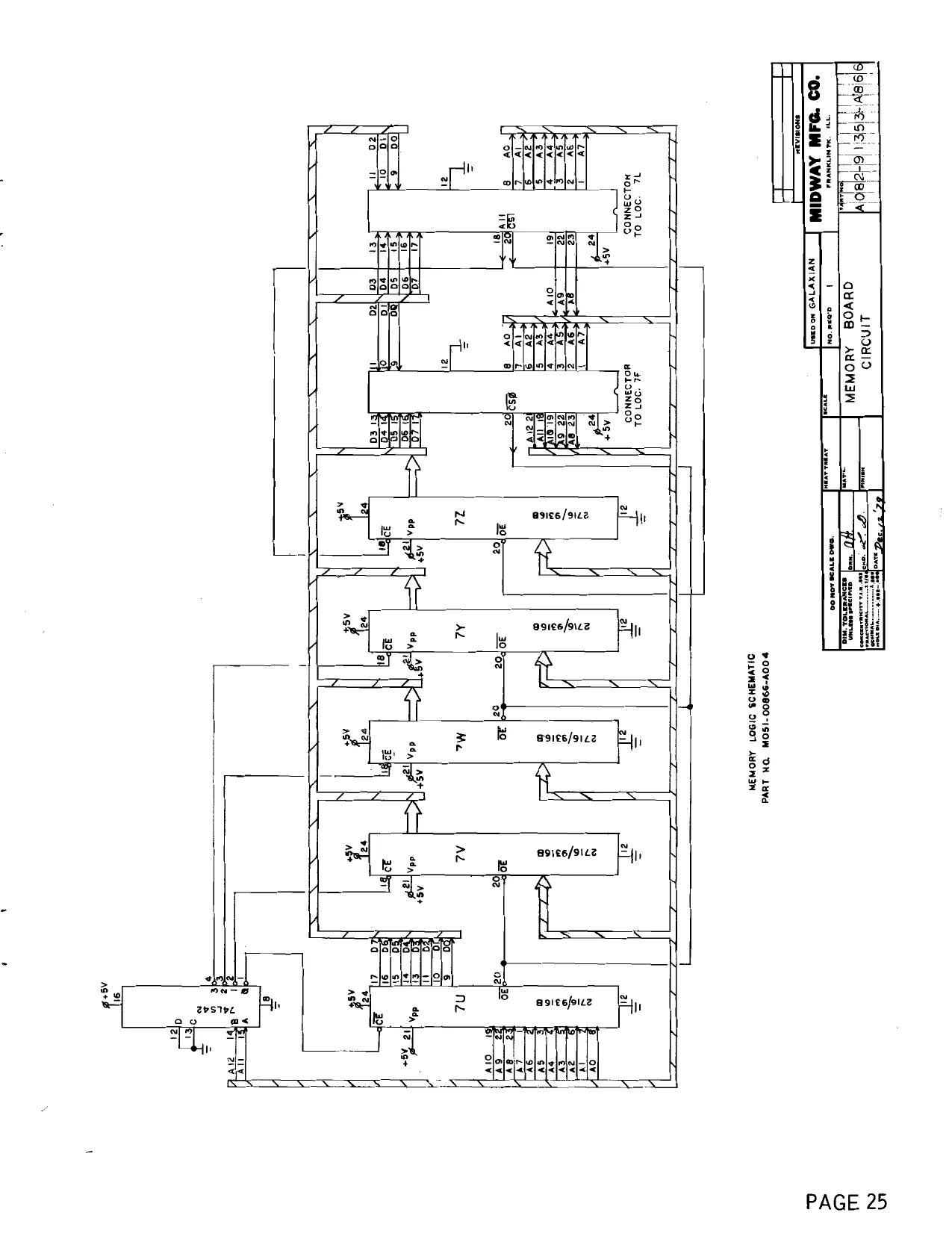
MEMORY LOGIC SCHEMATIC 25
WIRING SCHEMATIC - ‘A’’ VERSION 26
WIRING SCHEMATIC - "B’’ VERSION 27
WELLS-GARDNER MONITOR SCHEMATIC 28
THIS GAME MUST BE GROUNDED. FAILURE TO DO
SO MAY RESULT IN DESTRUCTION TO ELECTRONIC COMPONENTS.
COPYRIGHT @BY MIDWAY MFG. CO. ALL RIGHTS RESERVED, NO PART OF THIS PUBLICATION MAY SE REPRODUCED BY ANY MECHANICAL, PHOTOGRAPHIC, OR ELEC- TRONIC PROCESS, OR IN THE FORM OF A PHONOGRAPHIC RECORDING, NOR MAY IT BE TRANSMITTED, OR OTHERWISE COPIED FOR PUBLIC OR PRIVATE USE, WITHOUT PERMISSION FROM THE PUBLISHER FOR PERMISSION REQUESTS, WRITE: MIDWAY MFG. CO., 10750 W. GRAND AVE., FRANKLIN PARK, IL 60131
GENERAL INSTRUCTIONS FOR “GALAXIAN”
INSTALLATION
- Remove shipping cleats located on bottom of cabinet.
- Install four (4) provided leg levelers to bottom of cabinet and level cabinet,
- The power is.controlled by a switch located on top of the cabinet. Additional taps have been provided on the transformer to compensate for fluctuating line voltage
LINE VOLTAGE SAFETY SWITCH A line voltage safety switch has been provided for your protection. It is located on the right rear side of the cabinet in the back door area. When the back door is removed, it opens the circuit to the line voltage. To restore power (when servicing), pull switch fully out.
VOLUME CONTROL
The volume control pot is located on the Game Logic Board (P.C. A082-91352-A000). This pot controls the volume of all sounds and may be varied as desired by rotating pot control.
ADJUSTMENT SWITCHES
Located on Game Logic Board (P.C. A082-91352-A000) and may be adjusted as indicated on separate instruction card in back box area.
GAME LOGIC P.C. AO82-91352-A/BO0O0
ADJ. SW. CC] VOLUME_CONTROL ()
TO REMOVE CONTROL PANEL AND MONITOR DISPLAY GLASS
- Open coin door. Release two (2) clamps located below Control Panel on each side of cabinet. Disconnect control panel jack. Remove control panel. Remove monitor display glass. SP eh
CREDIT PUSH BUTTON SWITCH
Located in cash box area and is readily accessible by opening coin door. This switch is provided as a test aid and awards one credit without advancing coin meter.
TEST SLIDE SWITCH
Located in cash box area and is readily accessible by opening coin deor. When placed in “on” position this switch initiates test mode.
GAME BOARD TEST
If game board is good, the following information will be displayed on the screen: OK Coin Adjustment Setting Bonus Adjustment Setting No. of Gataxip Per Game Setting
RAM/ROM TEST {f any of the Rams or Roms are faulty, the following information will be displayed on the screen: “Bad Ram 1” — indicates bad Ram at location 7N or 7P. “Bad Ram 2” — indicates bad Ram at location 3F or 3H. “Bad Ram 3” — indicates bad Ram at location 4FH or 5FH. “Bad Ram” — indicates bad Rom on memory board.
*NOTE: — Early models were not equipped with memory boards. In these models, “Bad Rom” indicates bad Rom at location 7F or 7H.
CONTROL PANEL AND COIN SWITCH TEST
To verify operation of any switch, close switch in question. If the switch is operating properly, a game sound will emit when closure is made.
M05 1-00866-A012
MONITOR ADJUSTMENTS
Degaussing: All monitors are equipped with an automatic degaussing circuit which effecitvely demagnetizes the picture tube each time the monitor is turned on. The degaussing circuit will operate automatically each time the game is turned on after having been off for at least five (5) minutes. The degaussing is confined to the picture tube since the coils are mounted on the ferrous tube shield. Should any part of the chassis of cabinet become magnetized, it will be necessary to degauss the affected area by means of a manual degaussing coil. Move the coil slowly around the parts to be demagnetized, then slowly withdraw the degaussing coil for a distance of six (6) feet before disconnecting the coil from the A.C. power supply. Purity Adjustments: If degaussing fails to improve bad color, check for purity as follows. Position monitor to be facing
either north or south. Purity adjustments are most accurate while observing RED FIELD ONLY. Remove the interface printed circuit connector at the monitor. Turn BLUE and GREEN screen controls (shown below) fully counterclockwise.
SCREEN CONTROLS DRIVE —m RASTER oO oO 9O Oo oO ; RED GRN— BLU RED BLU ie
To obtain RED field, place service switch in RASTER position. Next, adjust the RED screen control to sufficient brightness to observe purity.
Loosen the yoke and slide the yoke back against the convergence coils assembly. Adjust for a uniform RED area in the center of the screen by spreading or rotating the purity magnet assembly located on the BLUE lateral magnet housing assembly. SLUE LATERAL ADJUSTMENT. (MUST BE LOCATED. OI ‘ON TOP? Purity:
Cj FIGURE A ~Alternate Blue Lateral Magnet and Purity Ring Assemblies ‘ON BOTTOM) FIGURE C
Spreading the tube increases the magnet strength and moves beams in a radial direction. Rotating the purity magnets moves beams in a circular path. ROTATING PURITY SPREADING TABS toss Qe OF PuRITY MAGNET dors in ‘AR PATH AND MOVES OOTS IN CIRCUS — RADIAL DIRECTION
129-4912
Figure 4.—Center Landing Adjustments
After purity has been attained, slide yoke toward the picture tube belli while observing entire screen. Position yoke for the best overall RED screen and tighten yoke. Preactivate BLUE and GREEN guns and observe all three beams. If the screen is not a uniform white, repeat purity adjustments. Place service switch in NORMAL position and reconnect interface connector at monitor.
CONVERGENCE ADJUSTMENTS: Before performing convergence adjustments, the monitor must be preheated for at least five (5) minutes. The convergence service switch is located to the right of the cash box and is accessed by opening coin door. Turn this switch momentarily “ON” then “OFF”. When the crosshatch pattern appears on the screen, turn the service switch back to the “ON” position. The crosshatch pattern will now remain on the screen.
Converge the monitor as follows:
10.
12.
13, CONVERGENCE Use either crosshatch or dot pattern for center convergence.
Converge center of screen with red, green and blue magnet and the blue lateral magnet.
Adjust R801 and R802 for convergence (parallelism) of R/G vertical center line.
Readjust center convergence if Necessary.
Adjust R804 to converge bottom R/G horizontal lines and R803 to converge top R/G horizontal lines at center line of screen.
Adjust R807 and L801 for straight horizontal blue center line.
Adjust R806 and R805 for uniform displacement of blue horizontal lines along center vertical lines.
Converge blue horizontal lines with R/G horizontal lines by adjusting the blue convergence magnet. Adjust ted and green magnets if necessary.
Repeat steps 6 through 8 if necessary.
Adjust alternately L803 and R809 for right and left side convergence of R/G vertical lines.
Adjust alternately L804 and R808 for convergence of R/G horizontal center line.
Converge center of screen and repeat steps 10 and 111 if necessary.
Minor touch-up adjustments may be made using the appropriate controls. SERVICE ADJUSTMENTS
STEPS 3 AND $ ADJUSTMENTS Figure 8.—Effect of R801, R804, R803 and R802 Adjustment
STEPS 6 AND 7 ADJUSTMENTS Figure 9.—Effect of R807, L801, R806 and R80S Adjustment
STEPS 10 AND 11 ADJUSTMENTS Figure 10.—Effect of L803, R809, L804 and R808 Adjustment
When monitor is satisfactorily converged, return service switch to “OFF” position, (game mode).
PROGRAM NO. 1 SWITCH ADJUSTMENTS
METHOD OF PLAY " sw. 1 sw. 2
| 1 COIN= 1 PLAY | OFF | OFF |
2 COINS = 1 PLAY ON OFF
| 1 COIN = 2 PLAYS | OFF | ON |
| FREE PLAY | ON | on |
BONUS GALAXIP SW.3 sw. 4
| NO BONUS GALAXIP | OFF | OFF |
| BONUS GALAXIP AT 4000 PTS. | ON | OFF |
| BONUS GALAXIP AT 5000 PTS. | OFF | ON |
| BONUS GALAXIP AT 7000 PTS. | ON | ON |
NUMBER OF GALAXIP PER GAME
SW.5 3 GALAXIP PER GAME OFF 5 GALAXIP PER GAME oN
MO51-00866-A006
PROGRAM NO. 2
METHOD OF PLAY
sw. 1 sw. 2
| 1 COIN =1PLAY | OFF | OFF |
| 2 COINS = 1 PLAY | oN | OFF |
| 1 COIN = 2 PLAYS | OFF | on |
| FREE PLAY | ON | on |
BONUS GALAXIP sw.3 sw. 4
| ‘NO BONUS GALAXIP | OFF | OFF |
| BONUS GALAXIP AT 3000 PTS. | oN | OFF |
| BONUS GALAXIP AT 4000 PTS. | OFF | on |
| BONUS GALAXIP AT 5000 PTS. | ON | oN |
NUMBER OF GALAXIP PER GAME
SW.5 2 GALAXIP PER GAME OFF 3 GALAXIP PER GAME oN
M051-00866-A005
NO. 866 — GALAXIAN — FRONT PICTURE
MIDWAY MFG. CO. ABALLY COMPANY
NO. 866 — GALAXIAN — FRONT PICTURE
ORDER BY PART NUMBER ONLY
0866-00901-0000 0866-00103-00XF 0866-00900-0000 M052-00050-0005 0866-00904-0000 085 1-00904-0000 M052-00090-0001 0017-00003-0294 0866-00902-00XF 0017-00101-0639 0017-00104-0022 0017-00103-0061 0017-00101-0775 0866-00903-0000 A090-00020-2001 A090-00057-0000 0090-00002-02GR 0017-00101-0555
0017-00102-0048 0017-00103-0026 0098-00900-0200
0017-00003-0187 0017-00009-0393 0017-00009-0033 0603-00131-0000 0586-00036-0000 0567-00106-0100 0017-00101-0025 A866-00036-0000 DESCRIPTION
UPPER DISPLAY PLEXI - 23” x 9” x 3/16” PLEX! RETAINING BRKT. (2 REQ'D.) MAIN DISPLAY PLEXI - 2-1/8” x 23” x 3/16” SPONGE RUBBER TAPE - 1/4 x 23” LG. T.V. BEZEL DISPLAY PLEX! (SMOKED) - 17-3/8” x 14” DOUBLE COATED TAPE - 1/2 x 17” LG. 19" COLOR MONITOR - COMPLETE CONTROL SHELF OVERLAY #8 - 32 x 1-1/4 CARRIAGE BOLTS (6 REQ’D.) #8 WASHER (6 REQ’D.) #8 - 32 HEX NUT W/SEMS. (6 REQ’D.) #6 x 1/2 PHIL. PAN HD. SCREW (2 REQ'D.) DECORATIVE CONTROL PANEL DOUBLE ENTRY COIN DOOR ASSY. COIN DOOR COUNTER METER ASSY. COIN DOOR FRAME #6 - 32 x 5/16 HEX HD. S.M.S. (3 REQ'D.) (MOUNTS COIN DOOR TO FRAME) LEG LEVELERS (4 REQ’D.) LEG LEVELER NUTS (4 REQ’D.) T-MOLDING - GREEN NOT SHOWN LIST 6" x 9" SPEAKER - 80HM, 9W. BLACK SPEAKER GRILL W/4, 1-1/2” SCREWS LATCH CLAMP (2 REQ’D.) STRIKE (2 REQ'D.) ON-OFF SWITCH SWITCH MTG. PLATE #8 x 1/2 SLOT. HEX HD. WD. SCR. (4 REQ'D.) TEST SWITCH & BKT. ASSY.
MIDWAY MFG. CO. A BALLY COMPANY
NO. 866 — GALAXIAN — OPENED BACK PICTURE
(8)
@)
®
o (3)
®
©)
MIDWAY MFG. CO. ABALLY COMPANY
NO. 866 — GALAXIAN — OPENED BACK PICTURE
ORDER BY PART NUMBER ONLY firem| part Ne | CDESCRIPTION, 0017-00003-0294 0866-00109-0000 0017-00101-0115 0017-00101-0639 0017-00101-0628 0017-00104-0022 0017-00103-0061 A866-00035-00XF 0017-00032-0071 A082-91352-A866 0624-00902-0600 0624-00902-0300 A866-00048-0000 A866-00054-0000 A866-00051-0000 A866-00053-0000 A866-00052-0000
A084-91353-A866 A097-00001-0000 0618-00117-0000 A623-00110-0000 A623-00013-0000 A624-00001-0000 0624-00101-0000 0017-00101-0628 0017-00104-0022 0017-00103-0061 0866-00905-0000 0017-00003-0419 19’ COLOR MONITOR & CHASSIS - COMPLETE MONITOR MTG. BRKT. #8 - 32 x 2" HEX MACH. SCREW (5 REQ'D.) #8 - 32 x 1-1/4 CARRIAGE BOLT #8 - 32 x 3/4 CARRIAGE BOLT (4 REQ'D.) #8 WASHER (10 REQ'D.) #8 - 32 HEX NUT SEMS. (10 REQ’D.) INTERLOCK SW. BRKT. ASSY. INTERLOCK SWITCH GAME LOGIC BOARD ASSY. P.C. SUPPORT BRKT. - 17” (2 REQ'D.) P.C. SUPPORT BRKT. - 2-1/2" (2 REQ'D.) TRANSFORMER BOARD ASSY. LOW VOLTAGE CABLE ASSY. POWER CABLE ASSY. - HIGH VOLTAGE COIN DOOR CABLE ASSY. - NOT SHOWN CONTROL PANEL CABLE ASSY. - NOT SHOWN
ADDITIONAL PARTS LIST MEMORY BOARD ASSEMBLY LOCK ASSY. - BACK DOOR VENT SCREEN (2 REQ’D.) COIN BOX ASSY. COIN BOX COVER ASSY. COIN BOX GUIDE BRKT. ASSY. COIN BOX GUIDE BRKT. #8 - 32 x 3/4 CARRIAGE BOLT (4 REOQ’D.) #8 STL. WASHER (4 REOQ'D.) #8 - 32 LOCK NUT SEMS. (4 REQ'D.) FISHPAPER SHIELD 4 IN. SQ. PIN EXTRACTOR TOOL (PIN POPPER)
MIDWAY MFG. CO. A BALLY COMPANY PAGE 9
NO. 866 — GALAXIAN — CONTROL ASSEMBLY
NO. 866 — GALAXIAN — CONTROL ASSEMBLY
ORDER BY PART NUMBER ONLY
A866-00028-0000 0017-00100-0025 0852-00106-0000 A852-00014-00XF 0017-00041-0616 A866-00027-0000 0852-00701-00XF 0017-00103-0011 0852-00101-00XF 0017-00101-0553 0017-00101-0637 0017-00104-0022 0017-00103-0061 0852-00103-00XF A852-00016-0000 0020-00202-0000 0017-00101-0737 WOOUNMAPWNH— [ITEM| PART N& DESCRIPTION
HANDLE ASSEMBLY “E-RING PLATE - FOLLOWER CONTROL SW. BRKT. & TOP PLATE ASSY. RUBBER BUMPER (2 REQ’D.) PIVOT BRKT. HUB & BEARING ASSY. PIVOT ROD #10 - 32 LOCK NUT BRACE MAIN BRKT. #6 - 32 x 1/4 SLT. PAN HD. M.S. (6 REQ'D.) #8 - 32 x 1" CARRIAGE BOLTS (4 REQ’D.) #8 STL. WASHER (4 REQ’D.) #8 - 32 HEX LOCKNUT SEMS. (4 REQ'D.) SWITCH BRACKET (2 REQ’D.) SWITCH ASSY. (2 REQ'D.) SWITCH PLATE (2 REQ’D.) #5 - 40 x 5/8 PAN HD. M.S. (4 REQ'D.)
MIDWAY MFG. CO. A BALLY COMPANY PAGE ll
COme NO. 866 — GALAXIAN — PUSH BUTTON ASSY.
NO. 866 — GALAXIAN — PUSH BUTTON ASSY.
ORDER BY PART NUMBER ONLY
BUTTON SPRING BUTTON HOUSING FLAT WASHER (2 REQ’D.) E-RING PUSH BUTTON ASSY. (FIRST 5 [TEMS) MOUNTING BRKT. 0017-00009-0384 0010-00593-0000 0017-00009-0376 0017-00104-0028 0017-00100-0025 A739-00012-0000 0586-00107-0000 0017-00103-0054 PAL NUT A739-00016-0000 SWITCH ASSY. 0020-00202-0000 SWITCH PLATE 0017-00101-0526 #5 - 40 x 9/16 PHIL. HD. M.S. (2 REQ'D.)
MIDWAY MFG. CO. A BALLY COMPANY PAGE 13
NO. 866 — GALAXIAN — FLUORESCENT FIXTURE ASSEMBLY OR
INCANDESCENT LIGHT ASSEMBLY
MIOWAY MFG. CO. A BALLY COMPAN'
—- = PK OOOH ODAP WH — NO. 866 — GALAXIAN — FLUORESCENT FIXTURE ASSEMBLY OR INCANDESCENT LIGHT ASSEMBLY ORDER BY PART NUMBER ONLY item] PART No | DESCRIPTION 0017-00003-0043 0017-00021-0005 0017-0003 1-0036 0017-00101-0573 0866-00108-0000 0017-00021-0096 0017-00003-0026 0017-00101-0593 0017-0002 1-0079 0017-00003-0019 0017-00101-0528 A866-00039-0000
0866-00113-0000 0017-00003-0135 0017-00003-0309 0017-00101-0626 0017-00103-0061 18 IN. FLUORESCENT LAMP - COOL WHITE FLUORESCENT LOCKS (2 REQ'D.) FLUORESCENT SOCKET (2 REQ'D.) #6 - 32 x 1/2 SLT. RND. HD. M.S. (2 REQ'D.) FLUORESCENT BRKT. ASSY. 2 PIN SOCKET CONNECTOR BALLAST #8 - 32 x 1/4 SLT. PAN HD. M.S. (2 REQ‘D.) STARTER HOLDER STARTER #5 - 40 x 3/4 R.H.M.S. (2 REQ'D.) FLUORESCENT CABLE ASSY. - NOT SHOWN
INCANDESCENT LIGHT ASSEMBLY USED AFTER GAME NO. 3,000 SOCKET MTG. BRKT. (2 REQ’D) LAMP SOCKET (2 REQ’D.) LAMP 12V., 25W. (2 REQ'D.) #8 - 32 x 3/4 SLT. PAN HD. M.S. (4 REQ’D.) #8 - 32 HEX NUT W/SEMS. (4 REQ'D.)
MIDWAY MFG. CO. ‘A BALLY COMPANY PAGE 15
NOTE:
MIDWAY’S BASIC COIN DOOR,
VARIATIONS ARE DEPENDANT ON
YOUR PARTICULAR GAME. NO. 866 — GALAXIAN — FRONT DOOR ASSY.
NO. 866 — GALAXIAN — FRONT DOOR ASSY.
ORDER BY PART NUMBER ONLY fmm Part Ne | —~—~SCéSCRIPTION.—_—_—=*d 0090-00902-0000 0090-00902-0100
0017-00101-0552 0090-00117-03XF 0090-00906-0000 0010-00007-0000 0090-00013-0200 0017-00005-0050 0090-00002-02BR 0017-00005-0041 0090-00901-0000 0090-00126-01XF 0017-00101-0528 0090-00903-0040 0090-00 143-0000 0017-00104-0002 0017-00007-0019 0017-00103-0005 0090-00010-0000 0017-00100-0018 0090-00131-0000 0090-00104-0000 0017-00101-0598 0010-00181-0100 0090-00129-00XF 0010-00134-0000 0090-00008-0000 0093-00155-00XF 0017-00100-0012 0093-00151-00XF 0090-00005-0000 0017-00101-0555 0017-00005-0039 0010-00557-2500 0017-00007-0132 0017-00101-0507 0090-00128-00XF A090-00061-0000
A090-00064-0000 DRESS PLATE DRESS PLATE (W/O PRESS BUTTON TO START GAME) #6 - 32 x 1/4 CARRIAGE BOLT (2) COIN ENTRY PLATE (25¢) PLASTIC START BUTTON COMPRESSION SPRING DOOR ASSY. DOUBLE ENTRY DOOR LOCK & KEY WITH SCREW & NUT DOUBLE DOOR FRAME 421 N.S. CAM DOOR SWITCH SWITCH BACKUP PLATE #5 - 40 x 3/4” LNG. M.S. 25¢ WINDOW COIN PLEX RETAINER SPLIT LOCK WASHER KEY HOOK #6 - 32 HEX NUT SW. PLATE & OILLITE ASSY. “E" RING SWITCH TOP & BTM. COIN CHUT W/BRKT. ASSY. #8 - 32 x 5/16 SCREW SPRING PIVOT POST SPRING ACCEPTOR FRAME ASSY. REJECTOR LEVER “EB” RING COIN GUIDE MTG. BRACKET COIN GUIDE ASSY. #6 - 32 x 5/16 SCREW COIN SWITCH TRIP WIRE PUSH-ON RING (BIK) #4 - 36 x 3/4 SCREW SWITCH BRKT. - DOOR TILT ANTI-STRING DEVICE ASSY. - OPTIONAL (REPLACES ITEM 30) ANTI-PENNY DEVICE ASSY. - OPTIONAL
MIDWAY MFG. CO. A BALLY COMPANY PAGE 17
Wk oxi " -
(ble AT&INASSV CHV08 YAWYOISNVYL — NVIXVTV9 — 998 ‘ON
NO. 866 — GALAXIAN — TRANSFORMER BOARD ASSEMBLY ORDER BY PART NUMBER ONLY item] part Ne [| SS CESCRIPTION, MT00-00082-0000 | TRANSFORMER - 115 VOLT MT00-00081-0000 | TRANSFORMER - 240 VOLT 0017-00003-0114 NOISE FILTER A031-00002-0000 TERMINAL STRIP ASSY. 0064-030XX-XXPX | 1N4004 400 V. DIODE 0720-00001-0200 2 POSITION FUSE CLIP 0017-00003-0103 FUSE 1A. SLO-BLO 0017-00003-0261 FUSE 1.5A. SLO-BLO 0720-00001-0400 4 POSITION FUSE CLIP 0017-00003-0169 FUSE 5A. (2 REQ’D.) 0017-00003-0001 FUSE 1A. (2 REQ’D.) 0017-00101-0637 #8 - 32 x 1-1/4 CARRIAGE BOLT (4 REOQ’D.) 0017-00103-0008 #8 - 32 HEX NUT (4 REO'D.) 0017-00101-0014 #6 x 1/2 SLT. HEX HD. WD. SCR. (12 REQ’D.) 0017-00101-0018 #6 x 3/4 SLT. HEX HD. WD. SCR. (4 REQ'D.) A866-00049-0000 LINE CORD ASSY. - NOT SHOWN Coon oaoafrwnr—
MIDWAY MFG. CO. A BALLY COMPANY PAGE 19
COMPONENT LAYOUT PART NO, MOSI-00866-A0OZ
H INDICATES O.1ME SOW. AXIAL LEAD CERAMIC CAR 7 2 3 4 5 é 7 oe oo ao z ome Hae A cant amc Fraisses| | [eter Bi prayed ‘ii ries ame oogoue eager
ALSO] ALS32 7ALSIEI K 7ALSIEL aLS74 | ©
©
74LS86) 7aLSI63 7ALSI63} oth Tg sacs HH
U 7ALS08 aiLsoe mise | brasil mLsi75 * bowed [=a] can 74500) AL S20 | ALSO pais | 74LS377 Tisaes | ALSI38 | 6 EAT SINK 068 08 ONs-xxHx
- , G- 7ALS08) ALS20 ALS283 AL S283 ALS02 nesses 7ALS38 apap see a + [
a [Horomia ont loYORGLA Om AN S2
AALS273, ALSO TALS367) AALS3E7, ALS273 AALS8 | A259 BRREH oh} == c—
IM56IO° 24 PIN SOCKET [ Mgélo SOMES ¥#4L SOO ae
§
oo lz Si 5:
L ALSI94 ALS? HLS273
ROM M66, Pa
K 7LSI94 ALS? J ALSIOS ALS? e667 re ° © H ALSB4 wie af ak 74 S08) [==] 36 3s ; faa] 24 PIN SOCKET i Dasese- 16
mALSIS7 syabas.. z 2
sieeee —, Hee TMI py HeHseBebeaeE8s
; AALSIS7 baisisr ALS? ALSIST 04 | LS367| ALSIB9 ALS368 a a
a LSA ALSTA SALSI39- ALSIO. braLso2| ALS367} ALS367| ALS3E8 Coa] :
(woe ‘WoO w20 ALSO 7474 wa ALS368 Pa
3 fesed ais3e6 7ALS86 TAL S86 PAS 86 basse 1 830483 ZBOA ; ' ©e
BeH rue
gl Ei 5 5 Om A pALSI64) ALS3O) ALSIE! 7ALSIE! ALSIEL ALSIE! oo f alle Flee 2 (ar [er]
GAME LOGIC BOARD ae
oo = oe = ry = l | RC.A082-91352-A000 gos
PART NO, MOSI-00866- 8002
AL LEAD CERAMIC CAR
4 5 oo ia ue Fine
7ALSI63) pr41$393| oR
7ALSIEL ALS?4 ogre
AALSIG!
ALSI7S
pALS74 Lav s V5
ALS273
ALSIS7 T5610 a25i23
FALSIS4 ALSIS7 ASIA ALS? | co Tsien anise
7ALSI94 a S| pALSI67 oo
daglo1gny, e101z Ce], Ges Gem [azz ALSIS7: 574LS08 oo 7) i
24 PIN SockeT ‘Sesieec~e09 ~~ Heel UTD nin
26 PIN SOCKET
Sesest-106 ay EB fgpaoaragueaeaee (TO
ALSIS7 YALS367| ALSIZ9 te
ALS pais367 ALS367
pratsoe|
aRREEE rot) ALSB6 280A
7ALSIGr TALSIGI oo or oS (azo a
GAME_LOGIC BOARD
- | J P.C.A082-91352- 5000. = BH S 222W], Caer} as Es Gan
This page carries no recoverable text. It is a drawing or a photograph. See the original scan.
GALAXIAN LOGIC BOARD
CHIP NUMBER FUNCTION
74LS00 Quad Two Input Nand 741.802 Quad Two Input Nor 7404 Hex Inverter
74.808 Quad Two Input And
T4LS10 Triple Three Input Nand 74LS20 Dual Four input Nand 74LS30 Eight Input Nand
T4LS32 Quad Two Input Or
TALS74 Dual “D" Flip — Flop T4LS86 Quad Two input Exclusive Or 7ALS107 Dual “JK” Flip — Flop TALS 138 Three to Eight Line Decoder 7418139 Dual Two to Flour Line Decoder
74.8157 Quad Two Input Multiplexer
74.8161 Four Bit Counter
TALS 163 Four Bit Counter
TALS 164 Eight Bit Shift Register
TALS174 Hex “D” Flip — Flop TALS175 Quad “D” Flip — Flop
7418194 Eight Bit Shift Register
74LS259 Eight Big Addressable Latch
T4LS273 Octal “D” Flip — Flop T4LS823 Four Bit Binary Adder TALS245 Octal Bus Transceiver T4LS366 Hex Bus Driver — Inverting 74.8367 Hex Bus Driver
74LS368 Hex Bus Driver — Inverting
TALS377 Octal “D” Flip — Flop
GALAXIAN LOGIC BOARD
CHIP NUMBER FUNCTION
74LS393 Dual Four Bit Binary Counter
27LS00 Ram
2114 Ram
TMS4045 Ram
AM9124 Ram
2102-2 Ram
AM9101 Ram
8304 Bus Driver — Bidirectional
8216 Bus Driver — Bidirectional
LM324 Quad Operational Amp
555 Timer
LM377 Audio Amp
z80 CPU
2716 Prom — 16K
1M5610 Prom
78GUIC Voltage Regulator
ULN2075 Quad Buffer
18.432 X-TAL
CD4066 Quad Electronic Switch
D44vM4 Transistor
GE6015 Transistor
MC 14066 Quad Electronic Switch
GEA15F Diode — Rectifier
Al4F Diode — Rectifier
1N4148 Diode — Rectifier
1N4736A Diode — Zener
D2316EC 16K Rom
D2364C 64K Rom
This page is a drawing, shown as the original scan.
slgcBio MONITOR ACK
. WONITOR INTERFACE BALLAST erbo
LU |-GRaY us.
ov. Mq-82 XFORMER = egecn
FRANKLIN PARK (LL. 60131
WIRING SCHEMATIC PART No, M03i-00866-A003
BLUZA ee f GAME LOGIC BOARD. coor jin4o04 i ! PC. A082 -91353-A866
bd = 2:8 das on rs _ e—R- 1 i Vs a tot _ x 1 = ‘tien ree
peste, | ee
os |
or '
TO COIN DooR & CONTROL PANEL 8. MONITOR CHASIS
. MIDWAY MFG. CO. PAGE 26 A BALLY COMPANY
oem, suv [-enay
WIRING SCHEMATIC PART No, MoSi-00866- 8003
SEP aM BE
o™~ GAME LOGIC BOARD RC. AOE2-91353-A866
actzov so/60H RSE Rte) FORA) 305 ‘70K
e0K ra
cys R7s! R734 C190 "wae, he
F310] | 30x) oxo 370 d Orxe | t Sooo e3 aoe = 8320] msoey °5%| @) a
ry ter Wee a Sa
cs te Lote Tn
= oT ‘ase Signy, R721 Jantar an: weal San aot BAe
a aa Pid
ay: i C788 i ad anes ‘itso
ee
iwrenrace Boare
CTA
lc708~cror “slo ois /s00
wt i y +210 49008
jess Gas Oe 22h
TK i ‘908 MAIN SUBMAIN. SUBMAIN SUB MAIN [ewe] [287] [ereen) (Convene (BRionTWEss] [EoLOR] [Fin] Grog
WELLS - MONITOR SCHEMATIC PART NO. MO5I-00087-A001 MONMTOR SCHEMATIC K 4500-57894
NOTES
This space is provided for personal notes