Assualt TM-324 1st Printing
Assault (Rev B) (Namco, 1988) · Technical Manual · 112 pages · 79 sections · original scan
This page is a drawing, shown as the original scan.
This page carries no recoverable text. It is a drawing or a photograph. See the original scan.
Assault: Operators Manual
with Ulustrated Parts Lists,
Schematics, and Wiring Diagrams
Assault is engineered and designed by Namco Ltd. Manufactured by Atari Games. Trademark and @ by Namco 1988.
© 1988 by Atari Games Corporation. All rights reserved.
No part of this publication may be reproduced by any mechanical, photographic or electronic process, or in the form of a phonographic recording, nor may it be stored in a retrieval system, transmitted, or otherwise copied for public or private use, without permission from the publisher. The game play, all graphic designs, this technical manual, its accompanying schematic diagrams, and the display manual are protected by the U.S. Copyright Act of 1976. This Act provides for substantial penalties for violating federal copyright laws. Courts can impound infringing articles while legal action is pending. If infringers are convicted, courts can order destruction of the infringing articles. In addition, the Act provides for payment of statutory damages of up to $50,000 per infringing transaction in certain cases. Infringers may also have to pay costs and attorneys’ fees and face an imprisonment of up to five years as well as fines of up to $250,000 in the case of individuals and up to $500,000 in the case of corporations. Atari Games Corporation will aggressively enforce its copyrights against infringers. We will use all legal means to immediately halt any manufacture, distribution, or operation of a copy of video games made by us. Anyone who purchases such copies risks forfeiting such a game.
Published by: Atari Games Corporation 675 Sycamore Drive P.O. Box 361110 Milpitas, California 95035
Printed in the U.S.A 8S
Produced by the Atari Games Technical Publications Department. Writer: Rosalind Hutton Illustrator; Mary Ohanessian Sumner Editor and Designer: Andrea Dencker
Notice Regarding Non-Atari» Parts
You may void the game warranty (printed on the inside back cover of this manual) if you do any of the following:
- Substitute non-Atari parts in the game.
- Modify or alter any circuits in the game by using kits or parts not supplied by Atari Games Corporation.
NOTE
This equipment generates, uses, and can radiate radio frequency energy, and if not installed and used in accordance with the instruction manual, may cause interference to radio communications. It has been tested and found to comply with the limits for a Class A computing device pursuant to Subpart J of Part 15 of Federal Communications Commission (FCC) Rules, which are designed to provide reasonable protection against such interference when operated in a commercial environment. Operation of this equipment in a residential area or modification to this equipment is likely to cause interference, in which case the user, at his own expense, will be required to take whatever measures may be required to correct the interference. If you suspect interference from an Atari game at your location, check the following:
- All ground wires in the game are properly connected as shown in the game wiring diagram.
- The power cord is properly plugged into a grounded three wire outlet.
- On games provided with an Electromagnetic Interference (EMI) ground cage, be sure the game printed-circuit boards (PCBs) are properly installed in the EMI Ground Cage and the end board is securely installed with all screws in place and tightened. If you are still unable to solve the interference problem, please contact Customer Service at Atari Games Corporation. See the inside front cover of this manual for service in your area.
iii
Table of Contents
Set-Up How to Use This Manual.. Inspecting the Game. Controls and Switches . DIP Switch Location Setting the Coin and Game Options. Game Play
Self-Test DIP Switch Settings Switch Test Game Options Sound Test... Port Test Convergence Test Color Test Game Statistics Converting Hexadecimal Numbers...
Maintenance Preventive Maintenance Preventive-Maintenance Intervals .. Opening the Control Panel... Maintaining the Joystick Cleaning the Coin Mechanism Cleaning the Interior Components... Repairs .... Removing the Video Displat Replacing the Video Display Replacing Static-Sensitive Devices... Removing the Speaker or Fluorescent Light
Illustrated Parts Lists
Schematics and Wiring Diagrams
Assault Statistics
Warranty
List of Illustrations
Figure 1-1 Figure 1-2
Figure 2-1 Figure 2-2 Figure 2-3 Figure 2-4 Figure 2-5 Figure 2-6 Figure 2-7 Figure 2-8
Figure 3-1 Figure 3-2
Figure 4-1 Figure 4-2 Figure 4-3 Figure 4-4 Figure 4-5 Figure 4-6 Figure 4-7 Figure 4-8
Figure 5-1 Figure 5-2 Figure 5-3 Figure 5-4
Table 1-1
Table 2-1 Table 2-2 Table 2-3 Table 2-4 Table 2-5
Table 3-1 Control and Switch Locations .... DIP Switch and Additional Volume Control Location
Switch Test Screen . Game Options Screen Sound Test Screen Convergence Test Screen .. Color Test Screen. First Statistics Screen. Second Statistics Screen.. Third Statistics Screen.
Opened Control Panel Joystick Maintenance
Cabinet-Mounted Assemblies Control Panel Assembly ... Joystick Assembly........... Switching/Linear (SL) Power Supply Assembly Coin Acceptors, Inc. Coin Door Assembly. Assault CPU PCB Assembly..... Assault Video PCB Assembly Assault End PCB Assembly ..
Assault CPU PCB Schematics .. Assault Video PCB Schematics Assault Main Wiring Diagram... Wiring Diagrams for Switching/Linear (SL) Power Supply, Hitron 5V/12V Switching Power Supply, and Coin Door...
List of Tables
Game Specifications
DIP Switch Settings Point Required For Extra Lives (EXTEND Settings). Maximum Length of Each Round in Seconds (RANK Settings: Game Options . Hexadecimal-to-Decimal Conversion,
Recommended Preventive-Maintenance Intervals
vi
Safety Summary
The following safety precautions apply to all game operators and service personnel. Specific warnings and cautions will be found in this manual whenever they apply.
How to Use This Manual
This manual is written for game operators and service personnel, and provides information for setting up, playing, testing, and maintaining your Assault™ game. The manual is divided into the following chapters: ° Chapter 1 contains set-up and game play information.
- Chapter 2 contains self-test procedures,
- Chapter 3 contains preventive maintenance and repair procedures.
- Chapter 4 contains illustrated part lists.
- Chapter 5 contains schematic and wiring diagrams. This chapter has information you need to set up and play your Assault game. Carefully read the information in this chapter before applying power.
Set-Up
This cabinet should be connected to a grounded threewire outlet only. If you have only two-wire outlets, we recommend that you hire a licensed electrician to install grounded outlets. Players can receive an electrical shock if the cabinet is not properly grounded.
Inspecting the Game
Please inspect your Assault game carefully to ensure that the game is complete and was delivered to you in good condition. Figure 4-1 shows the locations of the game parts. Table 1-1 lists space, power, and environmental requirements. Inspect the game cabinet as follows:
- Examine the exterior of the cabinet for dents, chips, or broken parts,
- Unlock and open the service door. Unlock and open the coin doors. Inspect the interior of the cabinet as follows: Table 1-1 Game Specifications
Characteristic Specification
Power Consumption —_ 150 V-A, 110 W RMS ‘Temperature +5° to +50° C (437° to +122° F) Humidity Not to exceed 95% relative Line Voltage 102 to 132 VAC (U.S. games) Width 25 1/4 in. (64 cm.) Depth 34 3/8 in. (87.3 cm.) Height 73 1/2 in. (186.7 cm.) Weight 290 Ibs, (131.8 kg.)
a. Ensure that all plug-in connectors (on the cabinet harnesses) are firmly plugged in. Do not force connectors together. The connectors are keyed so they fit only in the proper orientation. A reversed edge connector can damage a printed-circuit board (PCB) and will void your warranty. b. Ensure that all plug-in integrated circuits on each PCB are firmly plugged into their sockets. c. Inspect the power cord for any cuts or dents in the insulation. d. Inspect the power supply, Make sure that the correct fuses are installed. Check that the harness is plugged in correctly and that the fuse block cover is mounted in place. Check that the green ground wires are connected. e. Inspect other major sub-assemblies, such as the video display, printed-circuit boards (PCBs), and speaker. Make sure that they are mounted securely and that the ground wires are connected.
Self-Test Advance Coin Counter Self-Test Switch Nd Auxiliary Coin Volume Control
Figure 1-1 Control and Switch Locations
1-2
Controls and Switches The Assault controls and switches are located in two places besides the on/off switch at the rear. The primary controls are on the utility panel behind the upper coin door. Additional controls are mounted on the game PCB.
Power On/Off Switch The power on/off switch is located at the bottom rear of the cabinet. (See Figure 4-1.)
Volume Control The volume control is located on the utility panel behind the upper coin door. (See Figure 1-1.) You can also adjust the volume, treble, and bass by using the controls on the game PCB. Change these controls only after you have tried the adjustment on the utility panel. The controls on the PCB are shown in Figure 1-2. (The PCB also has a balance control, which is not used in this game since it has only one speaker.)
Self-Test Switch The self-test switch is located on the utility panel. See Chapter 2 for a complete description of the self-test.
Auxiliary Coin Switches The game has three auxiliary coin switches. One is the Set-Up
push button next to the self-test switch on the utility panel. The coin counter is not activated when you use this button. The other two switches are on the coin mechanisms. Use these auxiliary coin switches and button to give a player coin credits.
Self-Test Advance Button To advance to the next screen in the self-test, press the push-button switch next to the self-test switch on the utility panel. See Figure 1-1. (In the attract or play mode, this is an auxiliary coin switch.)
Coin Counter The coin counter is located on the utility panel inside the upper coin door. The coin counter records the number of coins deposited.
DIP Switch Location
The DIP switch is located on the game PCB inside the EMI enclosure. When you pull the game PCB out, you see the DIP switches as they appear in Figure 1-2.
Self-Test Switch Turning on DIP switch 1 puts the game into the selftest mode. If you enter the self-test by turning on DIP switch 1, the only way to return to the attract or play mode is to turn switch 1 off.
inaro’ —— Bh \ OR (han \ {EER eo WOO } \ [EEE / Cy Naat mn \ Ley eee SSL
Figure 1-2 DIP Switch and Additional Volume Control Location
Set-Up
Statistics Switch If you turn on DIP switches 2 and 5, the game accumulates and displays statistics in the the self-test.
Freeze Frame Switch Turn on DIP switch 8 to freeze any video frame on the game display.
Setting the Coin and Game Options
The Assault coin and game options are set in the Self- Test Mode. Refer to Chapter 2 for the recommended settings and the procedure for setting the options.
Game Play
This section of the manual describes the theme of the Assault game and the game play features.
Introduction Your mission is to reclaim your homeland by destroying the enemy forces that have taken over. You have an Assault tank, the supreme mobile weapon. Your tank has artillery guns and grenades, can perform Rapid Rolls to dodge enemy shots, and uses Power Wheelies to launch grenades. Controls and Play Your controls are two four-position joysticks with triggers. These controls make Assault like no other tank game. You have a quick, highly responsive vehicle with fast movement in all directions. To avoid enemy shots, Rapid Roll your tank left or right by moving both joysticks to the same side. To launch grenades, put the tank in the Power Wheelie position by moving
1-4 both joysticks to the outside, then pressing either trigger. Your grenades are triple the fire power of your tank’s standard shots. Your tank is always in the center of the screen no matter what direction you are going. With Assault’s 360degree scrolling playfield, the world rotates around you as you move. An arrow always points you towards the exit to the next level. The lift zone gives you an advantage over the invaders and a spectacular view of the playfield. Each lift zone is a five-sided platform on the playfield that flashes red when you can use it. When you drive onto the lift zone, your tank jets straight up to get a bird’s eye view of the surrounding terrain and enemy lines. From this overhead position, you can reconnoiter enemy forces and bomb enemy outposts. Fight your way through 11 different levels to seek out and destroy the invader’s headquarters. To succeed, you must:
- Dodge enemy gunfire with the Rapid Roll manuever
- Assault enemy lines with long-range powerful grenades launched from Power Wheelies.
- Destroy all enemy tanks you encounter to prevent rear attacks.
- Bomb enemy outposts and reconnoiter enemy emplacements using the lift zones.
- Protect yourself against enemy artillery using buildings and trees.
- Blow up the large cannons on each level while you avoid enemy attacks.
- Follow the-arrow to find the exit to the next level. Before you can exit, you must destroy the large cannons defending the enemy strongholds.
Fosssct Chapter 2
Self-Test
The Assault™ game tests itself and provides visual indications of the condition of the game circuitry and controls, Self-test information is displayed on the screen. You do not need any additional equipment. We suggest that you perform a self-test when you first set up the game, collect coins, or when you think the game is not working correctly. Use the self-test to check the game controls, check the game and option settings, change the game and option settings, and check the game statistics. The self-test switch is located on the utility panei behind the upper coin door. (See Figure 1-1.) The self-test advance button is the push button on the same panel. To move from one screen to the next, push the selftest advance button on the utility panel. When you turn off the self-test switch, the game returns to the attract mode.
Self-Test
DIP Switch Settings
You may want to turn on some of the DIP switches to get more game information. The location of the DIP switches is shown in Figure 1-2.
Table 2-1 DIP Switch Settings Switch On Result 1 Turns on self-test 2 and 5 Game collects and displays statistics 8 Freezes video frame
If you turn on switches 2 and 5, the game will accumulate and display statistics in the the self-test. If you turn on switch 1, you wil! go into the self-test. You can test the self-test switch on the utility panel by doing this. However, if you do enter the self-test by turning on DIP switch 1, you must leave the self-test by turning that same switch off. You can turn on DIP switch 8 to freeze any video frame in the game.
Switch Test
The first self-test screen is shown in Figure 2-1 and tests the various controls on the game. The game does not have a second set of player controls, so you cannot test START 2 or any of the PLAYER 2 controls.
SWITCH TEST DIPSW ss f2345678 TesTsw :
START 1 2
COINi ——-COIN2 PLAYER 1 UP up DOWN DOWN LeET LEFT FIRE RIGHT RIGHT LSTiCk RSTICK
Figure 2-1 Switch Test Screen
2-2 Test game controls by moving or pressing the controls. The part name changes from white to red if it is working correctly when you test it. If you have set any of the DIP switches on, they will be displayed in red. For more information about the DIP switches see the section above, DIP Switch Settings. If you entered the self-test by switching on DIP switch 1, you can test the self-test switch on the utility panel, called TESTSW. Otherwise, TESTSW is always red. Press down on the auxiliary coin switch on each coin mechanism to test COIN 1 and COIN 2. Press the start button to test START 1. Move the two joysticks and press the fire buttons on the joysticks to test these controls.
Game Options
Press the self-test advance button to move to this screen. Both the game options and the coin options are on this screen. This screen is shown in Figure 2-2. Move through the screen by pushing either joystick forward or back. Change an option setting by pushing either joystick left or right.
GAME OPTIONS 1 COIN 7 CREDIT. 4 CORN. 1 CREDIT 4 GAME; CREDIT: CONT 1 GAME CREDIT ATTRACT SGUND ON TYPE & FEIR: GEF
MYTANK 3 EXTEND c
RANK G CONTINUE ON ROUND SELECT ON COIN T
CON 2
START
Figure 2-2 Game Options Screen
Goin 1—You can have from 1 to 9 coins and 1 to 9 credits. This sets the left coin mechanism. If you set this option setting to more than one coin, the player must put the coins in the same coin mechanism in order for the game to start.
Coin 2—You can have from 1 to 9 coins and 1 to 9 credits. This sets the right coin mechanism. If you set this option setting to more than one coin, the player must put the coins in the same coin mechanism in order for the game to start. Start—This sets the number of credits required to begin the game. You can set this from 1 to 9 credits. The recommended setting is 1 credit. Coni—This sets the number of credits required to continue the game. You can set this from 1 to 9 credits. The recommended setting is 1 credit. Attract—This turns the sound in the attract mode on and off. The recommended setting is sound on. Type—This should always be set to C. It indicates the type of cabinet you have. Your game will not work correctly if you use any other setting. Flip—This does not apply to this game. It should always be set to OFF. Mytank—This is the number of lives the player receives to start a game. The recommended setting is 3. Extend—This is the number of points the player needs to receive another life and extend the game. The recommended setting is C. The settings of A, B, C, and D are shown in Table 2-2.
Table 2-2 Points Required For Extra Lives (EXTEND Settings)
| Lives 1st | 2nd | 3rd | After the 3rd life, |
Setting 1 more life every
| A | 20,000 | 80,000 | 150,000 | 100,000 points |
| B | 40,000 | 120,000 | 240,000 | 120,000 points |
| C | 50,000 | 150,000 | 300,000 | 150,000 points |
| D_ | 80,000 | 200,000 | 400,000 | 200,000 points. |
Rank—This is the number of seconds allowed in each round, The recommended setting is C. See Table 2-3. Continue—f this is set to ON, players can continue the game at the beginning of the round that they were last on. If this is set to OFF, players must start over at Round 1 (or if Round Select is on, players can start at Round 6). Round Select—If this is set to ON, the player can choose to start either at round 1 or at round 6. If round Self-Test
Table 2-4 Game Options
| Coin 1* | 142 | 3 | 4 | 5 | 67 | 8 | 9 | |
| Credits | 142 | 3 | 4 | 5 | 67 | 8 | 9 | |
| Coin 2# | 142 | 3 | 4 | 5 | 67 | 8 | 9 | |
| Credits | 1#2 | 3 | 4 «5 | 6 | 7 | 8 | 9 | |
| Start Coins 1¢2 | 3 | 4 | 5 | 6 | 7 | 8 | 9 | |
| Credits | 142 | 3 | 4 | 5 | 6 | 7 | 8 | 9 |
| Cont | Coins 142 | 3 | 4 | 5 | 6 | 7 | 8 | 9 |
| Credits | 142 | 3 | 4 | 5 | 6 | 7 | 8 | 9 |
Attract Sound On+ Sound Off
Type AB Ct
Flip On Off+ Extend AB C#D
| Mytank | 1 | 2 | 345 |
Rank AB C#D
Continue Ont = Off Round Select On Off
If these are set to more than one coin, the player must put the coins in the same coin mechanism in order for the game to begin. + Recommended settings
select is set to OFF, then the player can only start at round 1.
Sound Test
This screen tests the sound circuitry in the game. The communication test does not apply to this game, although you can see the numbers change as you push the joystick. The screen is shown in Figure 2-3.
Port Test
Nothing on this screen is used in Assault.
Convergence Test This test indicates the condition of the display size, centering, linearity, and convergence. The screen is shown in Figure 2-4.
- The four corners of the grid pattern should touch
Table 2-3 Maximum Length of Each Round in Seconds (RANK Settings)
| Round 1 | 2 | 3 | 4 | 5 | 6 | 7 | 8 | 9 | 10 | 1 |
Setting
| A | 150 | 180 | 120 | 140 | 380 | 240 | 475 | 175 | 250 | 300 | 300 |
| B | 135 | 160 | 110 | 130 | 360 | 210 | 150150 | 240 | 270 | 270 | |
| c | 120 | 150 | 90 | 110 | 330 | 180 | 120 | 120 | 210 | 240 | 240 |
| D100 | 140 | 80 | 100 | 300 | 150 | 100 | 100 | 180 | 210 | 200 |
2-3
Self-Test
SOUND TEST EM SOUND : a NOK SOUND. 0:
Figure 2-3 Sound Test Screen
centering, linearity, and convergence. The screen is shown in Figure 2-4,
- The four corners of the grid pattern should touch the four corners of the raster.
- Grid lines should show no pincushioning or barreling, and the lines should be straight within 3.0 mm.
ss ee bet a ie Wee Oe OD BH Figure 2-4 Convergence Test Screen
2-4 Figure 2-5 Color Test Screen
If your display does not meet these conditions, refer to the display manual that came with your game for adjustment procedures.
Color Test
The color test screen is shown in Figure 2-5. This test indicates the condition of the display color circuits.
Game Statistics
If you have DIP switches 2 and 5 set on, the game Statistics screens appear after the convergence and color test screens, The location of these switches is shown in Figure 1-2. Enter the statistical information on the statistics sheet at the back of this manual. You will have to convert some of the numbers from hexadecimal (base 16) to ordinary decimal. Follow the instructions in the section at the end of this chapter, Converting Hexadecimal Numbers. First Statistics Screen: The first screen is shown in Figure 2-6 and shows these statistics: Total Time—Total time in hours, minutes, and seconds the machine has been on since the statistics were reset or the machine was turned on. Play Time—Total time in hours, minutes, and seconds the machine has been played since the statistics were reset or the machine was turned on. Credit—Number of new, unique games played. Credits added to continue games are not counted. This number is in hexadecimal. See the section at the end of this chapter, Convertng Hexadecimal Numbers, for in-
AUTO DATA SAMPLING SCREEN 1
JOTAL TIME: SH OSM 21S:
PLAY TIME 3H 8M: 46S.
‘CREDIT COUNT
TOTAL
HIGH SCORE 38000
Figure 2-6 First Statistics Screen.
Two player (2P) credits is not used in this game. The one player (1P) credits and the total should always be the same.
High Score—The highest score achieved since the statistics were reset or the machine was turned on.
Second Statistics Screen: Shows the round and time every player life was lost. This screen does not count when or where the game ended. The numbers on this screen are in hexadecimal. See the section at the end
ROUND 4 TIME os 1.0
2.0
3.0
6.0
6.0
LS 8.0 o +
o
Seco o oc oo a ee e2c0oc co ob eee Non oe ee ee eee eee eee SSooc oan es oo oo kao
Figure 2-7 Second Statistics Screen Self-Test
of this chapter, Reading Hexadecimal Numbers, for information about converting hexadecimal numbers. The screen counts time in half-minutes, up to fifteen minutes, and shows all the rounds from 1 to 11. Scroll across and down the screen using the joystick. Third Statistics Screen: Lets you clear the statistics. If you do not want to clear the statistics, just leave the screen by pressing the self-test advance button or switching off the self-test switch. If you do want to clear the statistics, push either joystick forward and press the fire button. This clears all the statistics.
AUTO DATA SAMPLING SCREEN 2
DATA CLEAR? YES-ON NO-OFF:
MODE CHOICE LEVER ON AND PUSH FIBRE! THEN CLEAR
Figure 2-8 Third Statistics Screen
Converting Hexadecimal
Numbers
The statistics in Assault are displayed as hexadecimal numbers (base 16), not as ordinary decimal numbers. Each number can have as many as three digits. These numbers can look like 378, A30, 78, B7, ADF, or 789". Although some of these numbers look like ordinary decimal numbers, they are not. 378, for example, does not mean three hundred and seventy-eight. Use Table 2-5 to convert the one or two-digit hexadecimal numbers to ordinary decimal numbers. If you have three-digit numbers, use the equation below the table. Enter the converted numbers on the statistics sheet at the end of this manual.
Use this procedure to convert three-digit hexadecimal
- All hexadecimal numbers are shown in this typeface
Self-Test
numbers to ordinary decimal numbers.
- Use this formula: x 256) + ¢
- If you have any letters, change the letters into the ¢ x 16) +
ordinary decimal numbers they are equal to.
- Now multiply and add the numbers together. For example:
10C= (1 x 256) + (Cx 16) + C) C equals 12 in ordinary decimal numbers, so
Hexadecimal Decimal 00 0 o1 1 02 2 03 3 04 4 05 5 06 6 07 7 08 8 09 9 OA, 10 OB n oc 12 oD B OE 14 OF 15
10 16 u 7 12 18 3B 19 4 20 15 a 16 22 7 2B 18 24 19 25 1A 26 1B 7 1c 2B 1D 29 1E 30 1F 31 20 32. a 33 22 cs 23 35, 24 36 25, 37 26 38 7 39 28 40 2 a 2A 42 2B 43 2c 44 2D 45 2E 6 2F 47
30 48 31 49 32 50 33 51 34 52 35 53 36 54 37 55, 38 56
- 37 3A 58 3B 39. 3c 60 3D 6 3E 62 BF Cy Table 2-5 Hexadecimal-to-Decimal Conversion Hexadecimal
a
4a 4B 4c 4D 4E ar
3A 5B 3c 3D 5E SF
io CA B 6c 6D OE OF
n R B
B %6
A B 7c
TE TF Decimal
o7
ra
B ma B
83,
a
99.
105,
M1
113, write: = (1 x 256) + 12x 16) + (12) Multiply: = 256 + 192 + 12 And finally add: = 460
Hexa- Hexadecimal Decimal decimal Decimal
80 128 co} 192 81 129 cl 193, 82 130 C2 194 83 131 3 195 % 132 G 196 85 133 cs 197 86 14 ro 198 87 135 cr 199 88 136 ce] 200 8 137 Q 201 ‘8A 138 cA 202 8B 139 cB 203, ac +40 ec 204 8D 141 cD 205 SE 142 cE 206 oF 143 CF 207 ou 144 DO 208 on 145 DI 209 92 146 D2 210 3 147 D3 211 4 148 Dé 212 9 149 DS 213, % 150 D6 214 7 151 D7 215 98 152 D8 216 ” 153 DI 217 oA 154 DA 218 OB 155 DB 219 9c 156 pe 220 9D 157 DD 22) SE 158 DE 222 oF 159 DF 223
AO 160 EO 224 Al 161 EL 235 Az 162 Ez 226 sg 163 B 2 Ad 164 4 228 AS 165, ES 229, 46 166 56 20 AT 167 Ev 231 AB 168 ES 232 a 169 ED BB AA 170 EA 234 AB a7. EB 235, AC 172 EC 236 AD 173 ED 237 AE 174 EE 238 AF 175, EF 239 ‘BO 176 FO 240 BL 77 Fl 241 B2 178 F2 242 B3 179 B 243 Bt 180 F4 244 ‘BS 181 ee 245, ‘BE ‘182 F6 246 BT 183 F7 7 ‘BB 184 FB 248 Bo 185 F9 249 BA 186 FA 250 BB 187 FB 251 BC 188 FC 252 BD 189 FD 253, BE 190 FE 254 BF 191 FF 255, { |
Ii
+ Patient oy Be lqupapernapesial ¢ Lamp come moms haan ten tee Chapter 3
Maintenance
This chapter includes preventive maintenance and repair procedures for the Assault™ game components that have the most use. To assure maximum troublefree operation from this game, you should perform the preventive maintenance described in this chapter. Removal, disassembly, re-assembly, and replacement procedures are provided for components that might need to be repaired. If a game part is mentioned, but not illustrated, refer to Chapter 4, Illustrated Parts Lists, for information.
Maintenance
Preventive Maintenance
Preventive maintenance includes cleaning, lubricating, and tightening hardware. How often you perform preventive maintenance depends upon the game environment and frequency of play. However, you should regularly maintain the components listed in Table 3-1, Recommended Preventive-Maintenance Intervals.
To avoid possible electrical shock, turn off the game before performing any maintenance procedures.
Preventive-Maintenance
Intervals
For the best performance from your Assault game, perform the maintenance in Table 3-1 at the intervals specified. 78-6900402 1/4-nch Foam Tape
Not Shown
A046128-01 Control Panel Harness Assy
046110-01 Control Panel Plate
177010-240 Locknut ‘A046055-01 Right-Hand Joystick Assy Table 3-1 Recommended Preventive Maintenance Intervals Joystick Lubricate and clean every three months.
Coin Mechanism Inspect whenever you collect coins. Clean every three months.
Opening the Control Panel
- Open the upper coin door.
- Reach up through the coin door and unhook the latches on either side of the control panel.
- Pull the control panel up and disconnect the harness connector.
4, To replace the control panel, first fit the front edge into the slot in the cabinet. Reconnect the harness
036895-01 Molded Bezel.
‘A046055-02 Left-Hand Joystick Assy 2 7 (Not Shown)
a
a
75-5112B Carriage Bott
62-039 Red Switch
046121-01 Control Panel Decal
Figure 3-1 Opened Control Panel
3-2
connector. Now fit the controi panel in place and hook the latches from below.
Maintaining the Joystick
Maintain the joystick by cleaning the leaf switch in the handle, inspecting the pivot and actuator balls, and lubricating the joystick with lithium grease.
Cleaning the Leaf Switch
- Remove the control panel from the game.
- Take the handle off each joystick by unscrewing the four tamperproof screws on the long part of the handle. See Figure 3-1.
- Open the handle by unscrewing the two screws on the top of the handle.
- Inside each handle is a leaf switch. Carefully clean the contacts using electrical contact cleaner. Do not bumish the contacts.
- Check the gap between the contacts. The gap should be 0.06 inches. Make sure the leaf switch blades are straight. If the gap needs to be adjusted or the blades should be straightened, see Adjusting the Joystick Leaf Switch, in the maintenance part of this chapter. If you see any cracks in the blades of the switch, replace the switch.
- Lubricate the joystick before you put the handles back on.
Lubricating the Joystick
- With the handles off, remove the joystick assemblies from the control panel. Use a 3/8-inch nut driver or socket to loosen the nuts that hold the joysticks on the control panel.
- Use a 5/16-inch wrench and a screwdriver to remove the four long screws that hold the joystick together. See Figure 3-2.
- Take off the reinforcing plate, the 8-position plate, the actuator, and the lower housing.
- Lubricate the actuator ball on the end of the joystick shaft, the pivot ball below the upper housing, and the spring inside the upper housing. Use lithium grease.
- Put the joystick assembly back together. Fit the pin in the pivot ball into the slot in the lower housing. Maintenance
Make sure you put the reinforcing plate back on the bottom of the joystick.
- Replace the long screws and tighten the polymer. nuts.
- Replace the joystick assembly on the control panel.
- Reinstall the joystick handles,
- Use the Self-Test to make sure you have reassembled the joysticks correctly.
Cleaning the Coin
Mechanism
Use a soft-bristled brush to remove loose dust or foreign material from the coin mechanism. A toothbrush can be used to remove any stubborn build-up of residue in the coin path. After cleaning the coin mechanism, blow out all of the dust with compressed air.
Cleaning the Interior Components
Perform the following procedure to clean the components inside the cabinet.
- Turn the game power off and wait two minutes. Unplug the power cord.
- Remove the rear service door.
- Discharge the high voltage from the cathode-ray tube (CRT) before proceeding. The display assembly contains a circuit for discharging the high voltage to ground when power is removed. However, to make certain, always discharge the display as follows:
3-3
Maintenance Assault
72-SA4608B 6-19 Black Screw — ‘2 Places) inside Grip 178249-001 178248-001 for Left-Hand Joystick wager 178249-101 ‘ae ri for Right-Hand Joystick seaneela Switch Bracket 178249-003 Bia for Left-Hand Joystick 178247-001 178249-103 for Right-Hand Joystick 178247-002 for eane a dovstck for Left-Hand Joystick
160050-001 Trigger Switch
176025-4106 posstse.02 Tamper-Proof ‘Screw ‘Brown Jmpr Assy reese A046132-01 Black Jmpr Assy
A046053-01 7-1850F Upper Housin: 5 mrassy ° 3.4/8 Inches Lg Screw
041287-01 Lower Housing Lithium Grease ye
160044-001 pir Snap-Action | ‘Switch | | Y | 044390-01 176030-110 ba 4-20 Screw | Cushion Ring ex i 039714-01 039717-01 ? is iets 4-Position Plate
046054-01 Reinforcing Plate 177010-286 Polymer Nut
Figure 3-2 Joystick Maintenance
3-4 LPP h bbb aaid
a. Attach a length of solid gauge wire to the blade of a well-insulated screw driver. Maintenance
b. Attach the other end of the wire to an earth ground. c. Quickly touch the blade of the screwdriver to the CRT anode by sliding it under the anode cap. d. Wait two minutes and repeat step c.
4, Use a vacuum cleaner with a soft long-bristled brush attachment or use a soft-bristled paint brush to remove loose dirt and dust accumulated on the inside of the cabinet. Be sure to clean the electrical components thoroughly (power supplies, PCB assemblies, display, etc.).
Repairs
Repairs include the removal, disassembly, re-assembly, and replacement of game components, The following procedures are provided for components that may require repairs.
Removing the Video Display
Perform the following procedure to remove the video display. (See Figure 4-1.)
- Turn the game power off and wait two minutes. Unplug the power cord.
- Remove the rear service door.
- Be sure that the game power is tumed off before discharging the high voltage from the cathode-ray tube (CRT). The display assembly contains a circuit for discharging the high voltage to ground when power is removed. However, to make certain, always discharge the display as follows: a. Attach a length of solid gauge wire to a well-insulated screw driver or wood handle. b. Attach the other end of the wire to an earth ground. ¢. Quickly touch the blade of the screwdriver to the CRY anode by sliding it under the anode cap. d. Wait two minutes and repeat step c. 4, Disconnect the display harness connectors from the display.
- Remove the control panel from the game.
- Insert your finger into the hole in the cabinet below the video display shield, then pull the shield out and down.
- Remove the bezel careful from the cabinet. It is held in place with double-sided tape,
- Remove the two wood cleats on the left and right sides of the cabinet. Use a Phillips screwdriver to remove the two screws on each side.
- Use a 5/16-inch nut driver or socket to remove the four hex-washer head screws holding the display onto the metal mounting brackets in the cabinet.
- Carefully lift the display out through the front of the cabinet.
Maintenance
11 Replace the video display as described in the following procedure.
Replacing the Video Display
Perform the following procedure to replace the video display in the cabinet. (See Figure 4-1.)
- Carefully lift the video display into the front of the cabinet. N . Position the display so that the four holes in the video display mounting brackets align with the four holes in the top and bottom metal bracket.
- Install the four hex-washer head screws through the display frame and mounting brackets. 4, Use a 5/16-inch nut driver to tighten the screws. Be sure that the display is centered horizontally.
- Connect the display harnesses to the display,
- Install the two cleats that support the bezel and the display shield.
- Replace the bezel and display shield. Replace the control panel.
Adjusting the Joystick Leaf
Switch
If the tank gun does not fire every time you press the trigger, then you may need to adjust the leaf switch in the joystick.
- Remove the contro! panel from the game.
- Take the handle off the joystick by unscrewing the four tamperproof screws. See Figure 3-1. Open the handle by unscrewing the two screws on the top of the handle.
- First check the leaf switch to make sure it is clean. If it is not clean, clean it first, and see if that cures the problem. 4, The contacts should be 0.06 inches apart. If they are
3-6 not, use a pinball-type leaf switch adjuster to bend the back leaf until the contacts are the correct distance apart. Be sure that the blade remains straight.
- When the contacts are the correct distance apart, check to make sure the blades are straight. If they are not, use the leaf switch adjuster to straighten them.
- Reassemble the handle and install it on the joystick.
Removing and Replacing
the Game PC Boards
Perform the following procedure to remoye or replace the Assault Video, CPU, or End PC boards.The Video and CPU PC boards are inside the EMI cage and the End PC board is on the end of the cage. 1, Turn the game power off.
- Open and remove the service door,
- The vertical green PC board is the End PC board. It is connected to the CPU PC board and the video PC board inside the EMI cage.The EMI cage is the perforated metal box.
- Remove the 6 screws that hold the End PC board on the enclosure.
- Take off the edge connectors on the End PC board, 6, Carefully pull the End PC board out, along with the CPU and the video PC boards.
- Disconnect the CPU PC board from the End board.
- To replace the boards, reconnect and install them in the order that you removed them. Make sure the larger CPU PC board faces up, and the edge connectors on the End PC board are on top. Tightly lq]
nectors on the End PC board are on top. Tightly screw in all the screws holding the End PC board on the EMI cage.
Replacing Static-Sensitive
Devices
Be careful when you are working with static-sensitive devices on the game PC boards. Static charge that has built up in your body can cause a static-sensitive device to fail. Leakage from an improperly grounded soldering iron can also cause a static-sensitive device to fail. Before you replace a static-sensitive device, make sure it is actually defective. A static-sensitive device can appear defective due to leakage on a PC board. ‘To make sure a device is defective, ground any static voltages. Clean both sides of the PC board with flux remover or Maintenance
an eraser. For discrete FETs, clean thoroughly between the gate, drain, and source leads, Then test the device. If you replace a static sensitive device be careful when you handie the new static-sensitive device. The device may be packaged in conductive foam or may have a protective shorting wire attached to the pins. Remove the conductive foam just prior to inserting the device into its socket or soldering it to a PC board. Remove the shorting wire only after the device is inserted into its socket or aflerall the leads are soldered in place.
Removing the Speaker or Fluorescent Light
You will need an Apex A-2 square drive wrench to remove the screws holding the grill on the speaker or to remove the retainer holding the attraction panel on the cabinet.
3-7
This page carries no recoverable text. It is a drawing or a photograph. See the original scan.
Chapter 4
Illustrated Parts Lists
This chapter provides information you need to order parts for your game. Common hardware parts, such as screws, nuts, washers, and so on usually are not listed in the parts lists. The parts lists (except for the PCB parts lists) are arranged alphanumerically by Atari part number. All Aprefix numbers, which are assemblies, come first. Next are part numbers with six numbers followed by a hyphen (000598- through 201000-). Ending the list are part numbers with a two-number designation followed by a hyphen (00- through 99-). The PCB parts lists are arranged in alphabetical order by component. Within each section the parts are arranged numerically by part number. When you order parts, give the part number, part name, the number of this manual, and the serial number of your game. With this information, we can fill your order rapidly and correctly. We hope this will create less downtime and more profit from your games. Atari Games Customer Service phone numbers are listed on the inside front cover of this manual.
Illustrated Parts Lists Assault
046111-01 Speaker Grille 178056-002 1/2 Inch Foam Tape 79-6900402 casti3-ti 1/4 Inch Foam Bezel ape Leas a 171086-003 jetainer 12-inch Lamp orer2201 Fixture Attraction Decal 470003-003 046113-01 Fluorescent Attraction Shield Lamp
148007-104 ‘Speaker
046116-01 Shield
176027-4016 Washer Head 139021-002 ‘Screw Video Display
046084-01 Rear Service Door
046120-02 Right Decal ‘A046069-01 Control Panel Assy
171027-001 Coin Door
A046130-01 038091-01 Utility Panel Assy Molded Coin Box
Figure 4-1 Cabinet-Mounted Assemblies, Front View A046067-01 A LTT]
I]
Illustrated Parts Lists
Not Shown
‘A046126-01 Main Hamess: Assy
A046127-01 AC. Power Harness Assy
046120-01 Left Decal
178232-002 Lamp Retaining Clip
178126-002 ‘Tamperproot Key Wrench
99-090462 CPU PCB Assy
99-090463 Video PCB Assy
046123-01 Inner Decal
A046140-01 Power Supply Assy
Adjustable Glide A043055-01 On/Off Harness Assy EMI Enclosure
‘A044991-02 End PCB Assy
Figure 4-1 Cabinet-Mounted Assemblies, Rear View A046067-01 A
Illustrated Parts Lists Assault
Cabinet-Mounted Assemblies _ Parts List =
| Part No. | Description | ~ |
| A043055-01 | On/Off Harness Assembly | - |
| A044991-02 | Assault End PCB Assembly | — |
A046069-01 Control Panel Assembly (See Figure 4-2)
| A046126-01 | Main Harness Assembly | a |
| A046127-01 | A.C, Power Harness Assembly | — |
A046130-01 Utility Panel Assembly A046140-01 Power Supply Assembly (See Figure 4-4)
| 038091-01 | Molded Coin Box | _ |
046084-01 Rear Service Door 046111-01 Speaker Grille 046112-01 Video Display Bezel
| 046113-01 | Attraction Shield | —_ |
| 046114-01 | Attraction Retainer | — |
046116-01 Video Display Shield
| 046120-01 | Left Decal | _— |
046120-02 Right Decal 046122-01 Attraction Decal 046123-01 Inner Decal
| 139021-002 | 19-inch, Sharp Standard-Resolution Color Video Display (Acceptable substitute is Sanyo, | _ |
part no. 139021-001.)
| 148007-104 | Speaker | — |
170003-003 Fluorescent White 12-inch Lamp
| 171027-001 | Over/Under 25¢/25¢ Coin Door | _ |
171086-003 12-inch Lamp Fixture (Acceptable substitute is part no, 171086-004) 176027-4016 #10-24 Hex Washer Head Screw
| 178056-002 | 1/2 Inch Wide Foam Tape | — |
178126-002 Tamperproof Key Wrench 178232-002 Lamp Retaining Clip 78-3201 Adjustable Glide 78-6900402 1/4 Inch-Wide Foam Tape 99-090462 Assault CPU PCB Assembly (See Figure 4-6) 99-090463 Assault Video PCB Assembly (See Figure 4-7) The following are technical information supplements to the game:
| ST-324 | Assault Self-Test Label | __ |
TM-304 19-inch Sharp Standard Resolution Color Video Display Manual (If Sanyo video display is used, then TM-311 is substituted.) =
| T™-324 | Assault Operator's Manual with Schematics | — |
4-4
Not Shown
A046128-01 Control Panel Hamess Assy
Control Panel Illustrated Parts Lists
78-6900402 ‘A046055-01 1/4-Inch Foam Right-Hand Tape Joystick Assy
036895-01
‘046055-02 Left-Hand a Joystick Assy (Not Shown)
75-5112B Carriage Bolt
62-039 Red Switch
046121-01 Control Panel Decal
177010-240 Locknut
Figure 4-2 Control Panel Assembly A046069-01 A
Control Panel Assembly Parts List
Part No. Description
A046055-01 Right-Hand Joystick Assembly A046055-02 Left-Hand Joystick Assembly A046128-01 Control Panel Harness Assembly 036895-01 Black Molded Bezel 046110-01 Control Panel Plate 046121-01 Control Panel Decal 177010-240 #10-24 Polymer Locknut 62-039 Red Cap Switch
75-5112B #10-24 Black Carriage Bolt 78-6900402 1/2 Inch Wide Foam Tape
Illustrated Parts Lists Assault
72-JA4608B 6-19 Black Screw oo alae eran a for Left-Hand Joystick on 178249-101 for Right-Hand Joystick Outside Grip Soni raat t7easo-008 tsze7.a01 for Left-Hand tick = reso for Right-Hand Joystick for Right Hand Joystick ‘gaaa7-002: saa for Left-Hand Joystick
160050-001 “Trigger Switch
176025-4106 A046132-02
- ‘Brown Jmpr Assy (4 Places) A046132-01 Black Jmpr Assy
‘A046053-01 Upper Housing 72-1650F Assy 3 1/8 Inches Lg Screw
041287.01 Lower Housing
\ Lithium Grease
160044001 4 Snap-Action Switch
044390-01 Penetm | Cushion Ring
j
039714-01 039717-01 1 Actuator 4-Position Plate
046054-01 Reinforcing Plate 177010-236 Polymer Nut
Figure 4-3 Joystick Assembly A046055-01* and -02* B
4-6
Illustrated Parts Lists
Joystick Assembly Parts List
Part No. Description A046053-01 Upper Housing Assembly A046132-01 Black Jumper Assembly A046132-02 Brown Jumper Assembly 039714-01 Actuator
039717-01 4-Position Plate 041287-01 Lower Housing 044390-01 Cushion Ring 046054-01 Reinforcing Plate
107027-001 Lithium Grease 160044-001 Snap-Action Switch 160050-001 Trigger Switch 176025-4106 #10-32 Tamper Proof Screw 177010-236 #6-32 Polymer Nut 178247-001 Switch Bracket For Right-Hand Joystick 178247-002 Switch Bracket For Left-Hand Joystick 178248-001 Trigger 178249-001 Inside Grip For Left-Hand Joystick 178249-003 Outside Grip For Left-Hand Joystick 178249-101 Inside Grip For Right-Hand Joystick 178249-103, Outside Grip For Right-Hand Joystick 72-1650F #6-32 Screw, 3 1/8 Inches Long 72-JA4608B #6-19 Black Self-Tapping Screw
- A046055-01 is the right-hand joystick assembly. AO46055-02 is the left-hand joystick assembly.
Ilustrated Parts Lists Assault
‘A043367-08 12-Inch Black Jumper Assy 043396-01 ‘A043367-09 Power Supply Base 149008-001 op 179231-002 12-Inch White Jumper Hitron 5V/12V Switchin -Position Terminal Block Asey Power Supply Assy jupply Assy — g /
A042384-01 RFI Filter Assy .
46-2013002 3A, 250 V, Slow-Blow Fuse
179225-2201 1-Position Fuse Block
°
A044337-01 034544-01 Transformer Fuse Block Cover (A043367-01 3élnch Black Jumper Assy
Figure 4-4 Switching/Linear Power Supply Assembly A046140-01 A
Switching/Linear Power Supply Assembly Illustrated Parts Lists
Parts List
Part No. Description
A042384-01 RFI Filter Assembly A043367-01 3-Inch Black Jumper Assembly A043367-08 12-Inch Black Jumper Assembly A043367-09 12-Inch White Jumper Assembly 034544-01 Fuse Block Cover 043396-01 Power Supply Base A044337-01 ‘Transformer with Termination Assembly 149008-001 Hitron 5V/12V Switching Power Supply Assembly—see below 179225-2201 1-Position Fuse Block 179231-002 2-Position Terminal Block 46-2013002 3 A, 250 V, Slow-Blow Fuse
Hitron 5V/12V Power Supply Sub-Assembly Parts List
Part No. Description
Capacitors 99-211036 Capacitor, Metal Film, 0.047 pf, 250V 99-211037 Capacitor, Metal Film, 0.22 pf, 100V 99-211038 Capacitor, Metal Film, 0.1 uf, 400V 99-211039 Capacitor, Metal Film, 0.022 pif, 100V 99-211040 Capacitor, Ceramic, 1800pf, 2 KV, Z5V 99-211041 Capacitor, Ceramic, 0.01uf, 1 KV, Z5U 99-211042 Capacitor, Ceramic, 0.001 pf, 2 KV 99-211043 Capacitor, Ceramic, 470 Pf, 1KV, Z5P 99-211046 Capacitor, Electrolytic, 100 j3f, 200V 99-211047 Capacitor, Electrolytic, 1000 pf, 25V. 99-211079 Capacitor, DE7100F22M 99-211080 Capacitor, 1000 pf, 35V 99-211081 Capacitor, 470 pf, 25V 99-211082 Capacitor, 220 pf, 16V Diodes 99-211005 Diode, Schottky, $10SC4M 99-211007 Diode, Zener, 1N752A 99-211008 Diode, Rectifier, 1N4006 99-211009 Diode, Fast Recovery, RPG10B 99-211010 Diode, Fast Recovery, RPG10K 99-211011 Diode, Fast Recovery, RPG15B 99-211012 Diode, Switching, 1N4148 99-211076 Diode, 31DQ04
Illustrated Parts Lists Assault
Hitron 5V/12V Power Supply Sub-Assembly Parts List, Continued
| Part No. | Description | =— |
Inductors —
| 99-211084 | Inductor, 8 ph | — |
99-211085, Inductor, 9.8 ph
| 99-211086 | Inductor, 0.75 mh | _ |
99-211087 Inductor, 2.2 ph 99-211088 Inductor, 60 mh Resistors —_ 99-211014 Potentiometer, Trimming, 3K Ohm 99-211016 Resistor, Wire Wound, 150 Ohm, +5%, 2W
| 99-211017 | Resistor, Wire Wound, 33 Ohm, #5%, 2W. | = |
99-211018 Resistor, Wire Wound, 0.47 Ohm, +5%, 2W
| 99-211019 | Resistor, Wire Wound, 120 Ohm, +5%, 2W | — |
99-211020 Thermistor, 0.5 Ohm, +5%, 5W 99-211021 Resistor, 2.2K Ohm, +2%, 1/4W
| 99-211023 | Resistor, Carbon Film, 270 Ohm, +5%, 1/2W | __ |
| 99-211024 | Resistor, Carbon Film, 470 Ohm, +5%, 1/4W | _ |
99-211025 Resistor, Carbon Film, 47 Ohm, #5%, 1/4W
| 99-211026 | Resistor, Carbon Film, 330 Ohm, +5%, 1/4W | _ |
99-211027 Resistor, Carbon Film, 5.6 Ohm, +5%, 1/4W
| 99-211028 | Resistor, Carbon Film, 8.2 Ohm, +5%, 1/4W | — |
99-211029 Resistor, Carbon Film, 10 Ohm, +5%, 1/4W. 99-211030 Resistor, Carbon Film, 39 Ohm, +5%, 1/4W
| 99-211031 | Resistor, Carbon Film, 56 Ohm, +5%, 1/4W | a |
| 99-211032 | Resistor, Carbon Film, 1K Ohm, +5%, 1/4W | — |
99-211033 Resistor, Metal Film, 2K Ohm, +2%, 1/4W 99-211035 Resistor, Carbon Film, 2K Ohm, +5%, 1/4W
| 99-211077 | Resistor, 470 Ohm, 1/2W, +5% | — |
| 99-211078 | Resistor, 120K Ohm, 1W, +5% | ™ |
Transistors 99-211002 Transistor, NPN, 2SC1413A
| 99-211003 | Transistor, NPN, PE8050B. | — |
Miscellaneous
| 99-211059 | Heat Sink | _— |
99-211061 Heat Sink, 1.5mm 99-211089 Transformer, 4.75 mh
| 99-211083 | Transformer, Power | a |
| 99-211001 | Regulator, UA431AWC | _ |
| 99-211013 | Rectifier, Silicon-Controlled, $2800 | — |
4-10
Illustrated Parts Lists
S
4-11
Mlustrated Parts Lists Assault
99-10140 Panel Assembly
75-9485 “ Locknut ° i . 99-10116 nis Lever 99-10152 RIK Right Coin Inlet ; A
171006-035 Coin Mechanism 99-10147 Harness
75-944 S Locknut
99-10096 Fastener
99-10151 Lett Coin Inlet \.
7011-47 : Lamp
99-10080 Lamp Socket
] Se" 99-10105 72-9406S y Bar ‘Screw
99-10104
99-10042 thru 99-10045 “4
a Coin Switch Assembly 99-10154 Bracket Assembly
99-10153 Coin Return Box 99-10150
a Switch Cover
Coin Chute >
65-441 ™N in Switch Coin NN 99-10075 thru 99-10078 Switch Wires
99-10008 Retainer 75-14125 Screw
Figure 4-5 Coin Acceptors, Inc. Coin Door Assembly 171027-001 A
4-12 man
I | Assault Illustrated Parts Lists
99-10148 Lock Assembly
99-10160 Coin Inlet Housing
72-HA1404C Screw
a SS * 99-10161 99-10139 |~+—_—— Side Entry Button Assy Coin Door
‘Spring 99-10148 Lock Assembly
99-10141 Coin Return Cover
§ 99-10117 Coin Return Door
72-JA1405B <—— 99-0144 Screw Channel Clip
99-15066 Screw
99-10149 Service Door
038091-01 Coin Box
99-10143 Frame
The acceptable substitute for this door (and the one used in games manufactured in Ireland) is the Coin Controls Ltd. Coin Door Assembly, part number 171034-001. You can obtain a free Coin Controls Ltd. ‘supplement (part, no. CO-305-01) that has illustrations and a parts list. Write to Atari Games Ireland Limited, Tipperary Town, Ireland. Telephone 062-52155.
Figure 4-5 Coin Acceptors, Inc. Coin Door Assembly, Continued 171027-001 A
4-13
Illustrated Parts Lists Assault
Coin Acceptors, Inc. Coin Door Assembly Parts List —_
| Part No. | Description | — |
| 65-441C | Coin Switch | . |
70-11-47 Miniature Bayonet Lamp 72-9406S #4-40 x 3/8-Inch Truss-Head Screw 72-HA1404C #4-40 x 1/4-Inch Pan-Head Screw
| 72-JA1405B | #4-40 x .31-Inch Pan-Head Screw | a |
75-14128 #4-40 x 3/4-Inch Pan-Head Screw 75-9948 #4-40 Locknut 99-10008 Retainer
99-10042 Coin Switch Assembly for Belgian 5 Fr and U.S. 25¢
| 99-1043 | Coin Switch Assembly for German 1 DM, Japanese 100 Yen, Swiss 1 Fr | — |
99-10044 Coin Switch Assembly for German 2 DM, Italian 100 L, U.S. $1.00 99-10045 Coin Switch Assembly for Australian $.20, German 5 DM, British 10 P
| 99-10068 | Coin Return Chute | — |
99-10075 Switch Wire (included in coin switch assembly 99-10043)
99-10076 Switch Wire (included in coin switch assembly 99-10042)
| 99-10077 | Switch Wire (included in coin switch assembly 99-10044) | — |
99-10078 Switch Wire (included in coin switch assembly 99-10045)
| 99-10080 | Lamp Socket | — |
99-10081 Key Holder 99-10096 Fastener
| 99-10104 | Bar Retainer | — |
| 99-10105 | Bar | — |
99-10115 Spring .
| 99-10116 | Plastic Coin Return Lever | — |
| 99-10117 | Steel Coin Return Door | —_ |
99-10139 Coin Door
| 99-10140 | Coin Door Inner-Panel Assembly | — |
99-10141 Die-Cast Coin Return Cover
| 99-10143 | Coin Door Frame | __ |
99-10144 Channel Clip 99-10147 Harness 99-10148 Lock Assembly 99-10149 Service Door 99-10150 Switch Cover 99-10151 Left Coin Inlet 99-10152 Right Coin Inlet 99-10153 Coin Return Box 99-10154 Bracket Assembly
99-10160 1-Inch Wide Die-Cast Coin Inlet Housing
99-10161 25¢ Amber Side-Entry Coin Button Assembly
99-15066 Screw for Clamp 171006-035 Metal Coin Mechanism for U.S. 25¢
4-14
TT N Illustrated Parts Lists
S
This page reads as a drawing: its text was drawn rather than typeset, and comes out in fragments. See the original scan.
This page reads as a drawing: its text was drawn rather than typeset, and comes out in fragments. See the original scan.
Illustrated Parts Lists Assault
Assault CPU PCB Assembly Parts List
Part No. Description
Capacitors 99-090172 Capacitor, Ceramic, 100pF, 25V 99-090411 Capacitor, Ceramic, 1000pF, 25V 99-090412 Capacitor, Ceramic, 3pF, 25V 99-090171 Capacitor, Ceramic, 22pF, 25V - 99-090174 Capacitor, Ceramic, 0.01pF, 25V 99-090175 Capacitor, Ceramic, 0.1pF, 25V 99-090413 Capacitor 99-090414 Capacitor, Ceramic, 0.001pF, 50V 99-090415 Capacitor, Ceramic, 0.0022pF, 50V 99-090266 Capacitor, Ceramic, .0047pF, SOV, +10% 99-090416 Capacitor, Ceramic, 0.022pF, 50V 99-090180 Capacitor, Ceramic, .033pF, 50V, +10% 99-090417 Capacitor, Ceramic, 0.12pF, 50V 99-090267 Capacitor, Ceramic, .01pF, 50V, +10% 99-090418 Capacitor, Electrolytic, 1F, 50V 99-090419 Capacitor, Electrolytic, 2.2HF, 50V 99-090269 Capacitor, Electrolytic, 10pF, 16V 99-090347 Capacitor, Electrolytic, 22yF, 16V 99-090270 Capacitor, Electrolytic, 47pF, 16V 99-090420 Capacitor, Electrolytic, 100pF, 10V 99-090273 Capacitor, Electrolytic, 100uF, 16V 99-090421 Capacitor, Electrolytic, 220F, 10V 99-090422 Capacitor, Electrolytic, 470pF, 10V 99-090423 Capacitor, Electrolytic, 2200pF, 16V 99-090424 Capacitor, Electrolytic, 100pF, 6.3V 99-090350 Capacitor, Electrolytic, 47pF, 50V Integrated Circuits 136065-1101 Integrated Circuit, EPROM, AT MPO, 11D 136065-1102 Integrated Circuit, EPROM, AT MP1, 13D 136065-1103 Integrated Circuit, EPROM, AT SPO, 11K 136065-1104 Integrated Circuit, EPROM, AT SP1, 13K 136065-1105 Integrated Circuit, EPROM, AT DO, 13S 136065-1106 Integrated Circuit, EPROM, AT D1, 13P 136065-1107 Integrated Circuit, EPROM, AT SO, 7] 136065-1108 Integrated Circuit, ROM, AT VOI-1, 3M 136065-1109 Integrated Circuit, ROM, AT CHR-0, 11N 136065-1110 Integrated Circuit, ROM, AT CHR-1, 11P 136065-1111 Integrated Circuit, EPROM, AT SHA, 7N 99-090110 Integrated Circuit, 741804 99-090111 Integrated Circuit, 74/808 99-090115 Integrated Circuit, 741874 99-090120 Integrated Circuit, 7418157 99-090244 Integrated Circuit, 7418244 99-090124 Integrated Circuit, 7415245 99-090288 Integrated Circuit, 74F04
4-18
Hh odd. Mlustrated Parts Lists
Assault CPU PCB Assembly
Parts List, Continued
Part No. Description
99-090313 Integrated Circuit, 74F138 99-090314 Integrated Circuit, 74F244 99-090315, Integrated Circuit, 74F374 99-090362 Integrated Circuit, 74815 99-090363 Integrated Circuit, 744C240 99-090364 Integrated Circuit, 74HC74 99-090291 Integrated Circuit, 74HC175 99-090365 Integrated Circuit, CPU, HD68000-12 99-090366 Integrated Circuit, CPU, MC68000G12 99-090367 Integrated Circuit, CPU, 68BO9EP 99-090368 Integrated Circuit, CPU, HD68B09E 99-090136 Integrated Circuit, TMM2018D-45 (45NS) 99-090369 Integrated Circuit, RAM, MB8464A-15-SK 99-090370 Integrated Circuit, RAM, MPD4364CX-15 99-090371 Integrated Circuit, RAM, HM6225GP-120 99-090372 Integrated Circuit, RAM, MSM5256AP-12 99-090373 Integrated Circuit, RAM, MPD4325GC-120 99-090374 Integrated Circuit, RAM, SRM2025GLC12 99-090375 Integrated Circuit, RAM, MB84256-10 99-090376 Integrated Circuit, RAM, M5M5178-55 99-090377 Integrated Circuit, RAM, M5M5179-55 99-090378 Integrated Circuit, RAM, MB8422-12 99-090379 Integrated Circuit, RAM, HM6525GBSP-12 99-090380 Integrated Circuit, PAL, 1618, SYS87B-1 99-090381 Integrated Circuit, PAL, 16L8, SYS87B-2 99-090382 Integrated Circuit, PAL, 12110-2, SYS87B-3 99-090383, Integrated Circuit, EEPROM, HNS58C65P-25 99-090155 Integrated Circuit, Custom 95 99-090300 Integrated Circuit, Custom 116 99-090303 Integrated Circuit, Custom 121 99-090318. Integrated Circuit, Custom 123 99-090384 Integrated Circuit, Custom 137 99-090385 Integrated Circuit, Custom 139 99-090386 Integrated Circuit, Cusiom 140 99-090387 Integrated Circuit, Custom 145 99-090388 Integrated Circuit, Custom 148 99-090389 Integrated Circuit, Custom 149 99-090390 Integrated Circuit, Custom 156 99-090391 Integrated Circuit, Custom 65 99-090248 Integrated Circuit, Op-Amp, TLO84CN 99-090392 Integrated Circuit, Op-Amp, LA6082S
99-090393 Integrated Circuit, Audio Amp, LA4700
99-090147 Integrated Circuit, YM2151 99-090158 Integrated Circuit, DAC, YM3012 99-090394 Integrated Circuit, DAC, LC7880 99-090322 Integrated Circuit, TA7630
4-19
Illustrated Parts Lists
Assault CPU PCB Assembly Parts List, Continued
Part No. Description 99-090395 Integrated Circuit, TA7376 99-090324 Integrated Circuit, MB3771 99-090396 Integrated Circuit, Voltage Regulator, 78L05 99-090320 Integrated Circuit, 78L06 99-090323, Integrated Circuit, LB1760 99-090398 Integrated Circuit, PC900 99-090399 Integrated Circuit, PC910 Resistors 99-090351 Potentiometer,10K Ohm 99-090309 Resistor, SIP,1K Ohm 99-090305 Resistor, SIP,100 Ohm, 1/8W 99-090307 Resistor, SIP.470 Ohm, 1/8W 99-090332 Resistor, SIP,1K Ohm, 1/8W 99-090461 Resistor, SIP,4.7K Ohm, 1/8W 99-090333 Resistor, SIP,1.2K,1/8W 99-090252 Resistor, SIP,2.2K Ohm X 4, 1/8W. 99-090401 Resistor, SIP,2.2K Ohm, 1/8W 99-090306 Resistor, SIP,2.7K Ohm, 1/8W 99-090185 Resistor, SIP,4.7K Ohm X 8, 1/8W 99-090183, Resistor, SIP,1K Ohm X 4, 1/8W 99-090402 Resistor, SIP,4.7K Ohm, 1/8W 99-090336 Resistor, SIP,10K Ohm, 1/8W 99-090403 Resistor, 2.2 Ohm, 1/4W 99-090404 Resistor, 10 Ohm, 1/4W 99-090405 Resistor, 22 Ohm, 1/4W 99-090406 Resistor, 47 Ohm, 1/4W 99-090407 Resistor, 75 Ohm, 1/4W 99-090255 Resistor, 100 Ohm, +5%, 1/4W 99-090408, Resistor, 220 Ohm, 1/4W $9-090189 Resistor, 330 Ohm, £5%, 1/4W 99-090192 Resistor, 560 Ohm, £5%, 1/4W 99-090188 Resistor, 680 Ohm, +5%, 1/4W 99-090193, Resistor, 1K Ohm, +5%, 1/4W 99-090257 Resistor, 2.2K Ohm, #5%, 1/4W 99-090194 Resistor, 4.7K Ohm, +5%, 1/4W 99-090196 Resistor, 10K Ohm, +5%, 1/4W 99-090331 Resistor, 100K Ohm, 1/4W, +5% 99-090199 Resistor, 1M Ohm, +5%, 1/4W 99-090409 Resistor, 4.7M Ohm, 1/4W 99-090410 Resistor, 270 Ohm, 1/8W Transistors 99-090328 ‘Transistor, 25C2236-Y 99-090310 Transistor, 25A1015-Y 99-090397 Transistor, 2SC1815-Y 99-090311 Transistor, 25C2320-E I} |
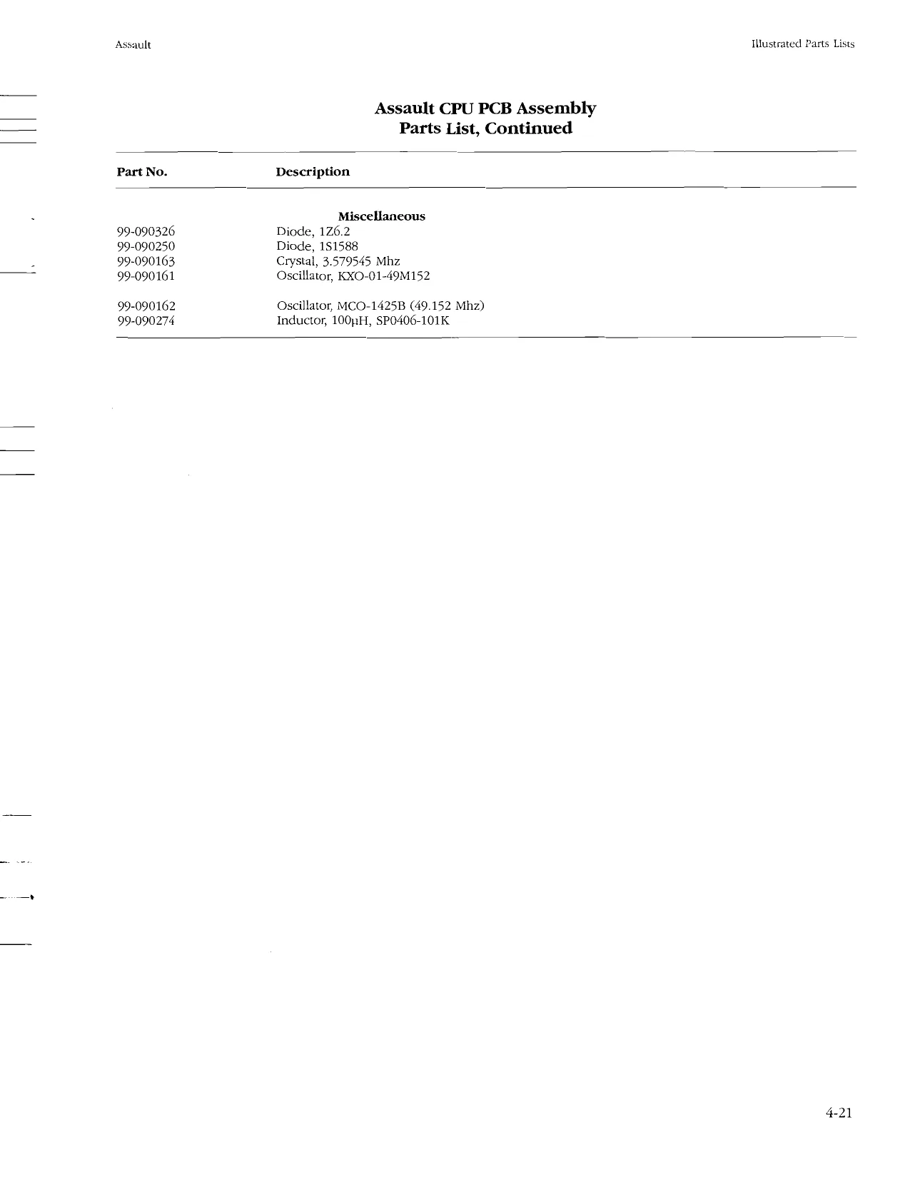
This page is a drawing, shown as the original scan.
This page reads as a drawing: its text was drawn rather than typeset, and comes out in fragments. See the original scan.
Hilustrated Parts Lists
Assault Video PCB Assembly Parts List
Part No. Description Part No. Description
Capacitors 99-090126 _ Integrated Circuit, 7418273
| 99-090413 | Capacitor | 99-090128 | Integrated Circuit, 7415374 |
| 99-090459 | Capacitor, 220PE,12V | 99-090131 | Integrated Circuit, 741S378 |
| 99-090460 | Capacitor, 470pE, 6.3V | 99-090428 | Integrated Circuit, 7419541 |
Integrated Circuits 99-090429 Integrated Circuit, 74F00
| 136065-1112 | Integrated Circuit, EPROM, AT OBJ-0, 5B | 99-090288. | Integrated Circuit, 74F04 |
| 136065-1113 | Integrated Circuit, EPROM, AT OBF-1, 4B | 99-090430 _ Integrated Circuit, 74F10 | |
| 136065-1114 | Integrated Circuit, EPROM, AT OBJ-2, 5D | 99-090113 | Integrated Circuit, 74F20 |
136065-1115 Integrated Circuit, EPROM, AT OBJ-3, 4D 99-090431 Integrated Circuit, 74F32
| 136065-1116 | Integrated Circuit, EPROM, AT OBJ-4, 5C | 99-090432 | Integrated Circuit, 74F74 |
| 136065-1117 | Integrated Circuit, EPROM, AT OBJ-5, 4C | 99-090313 | Integrated Circuit, 747138 |
| 136065-1118 | Integrated Circuit, EPROM, AT OBJ-6, 5F | 99-090454 | Integrated Circuit, 74F157 |
136065-1119 Integrated Circuit, EPROM, AT OBJ-7, 4F 99-090433 Integrated Circuit, 74F161
| 136065-1120 | Integrated Circuit, ROM, AT ROZ-0, 1A | 99-090434 | Integrated Circuit, 74F175 |
| 136065-1121 | Integrated Circuit, ROM, AT ROZ-1, iB | 99-090435 | Integrated Circuit, 74F240 |
| 136065-1122 | Integrated Circuit, ROM, AT ROZ-2, 1C | 99-090315 | Integrated Circuit, 74F374 |
136065-1123 Integrated Circuit, ROM, AT ROZ-3, 1D 99-090436 Integrated Circuit, RAM, TMM2018AP-
| 136065-1124 | Integrated Circuit, ROM, AT ROZ-4, 3A | 99-090438 | Integrated Circuit, RAM, MB8464-10-SK |
| 136065-1125 | Integrated Circuit, ROM, AT ROZ-5, 3B | 99-090296 | Integrated Circuit, M5M5256AP-70 (70NS) |
| 136065-1126 | Integrated Circuit, ROM, AT ROZ-6, 3C | 99-090455 | Integrated Circuit, Custom 102 |
| 136065-1127 | Integrated Circuit, ROM, AT ROZ-7, 3D | 99-090441 | Integrated Circuit, Custom 106 |
| 99-090108 | Integrated Circuit, 74LS00 | 99-090443 | Integrated Circuit, Custom 134 |
| 99-090110 | Integrated Circuit, 741504 | 99-090444 | Integrated Circuit, Custom 135 |
| 99-090425 | Integrated Circuit, 741830 | 99-090384 | Integrated Circuit, Custom 137 |
| 99-090115 | Integrated Circuit, 741874 | 99-090445 | Integrated Circuit, Custom 146 |
| 99-090426 | Integrated Circuit, 741886 | 99-090456 | Integrated Circuit, MOS |
| 99-090120 | Integrated Circuit, 74L$157 | 99-090457 | Integrated Circuit, PAL |
| 99-090123 | Integrated Circuit, 7418174 | 99-090458 | Integrated Circuit, PAL |
99-090244 Integrated Circuit, 7418244 Resistor 99-090191 Resistor, 470 Ohm, #5%, 1/4W
Illustrated Parts Lists
Figure 4-8 Assault End Board Assembly A044991-02
Assault End Board Assembly Parts List
Part No. Description
140006-271 Capacitor, Filter, 270 pf, 50V, 6A. 140006-222 Capacitor, Filter, 2200 pf, 50V, 6A 179174-056 Connector, Edge, 56 Ckt, .156 x .200
4-24 hl || 4 | |
LT | Chapter 5
Schematics and Wiring Diagrams
Figure 5-1 Figure 5-2
Figure 5-3
Figure 5-4 This chapter contains the schematics and wiring diagrams for your game. These are arranged in the following order:
Assault™ CPU PCB Assembly Schematic Diagrams Assault Video PCB Assembly Schematic Diagrams Assault Main Wiring Diagram
Wiring Diagrams for Switching/Linear (SL) Power Supply, Hitron 5V/12V Switching Power Supply, and Coin Door Page
5-2 to 5-37
5-38 to 5-53
5-54 to 5-55
5-56 to 5-57
This page reads as a drawing: its text was drawn rather than typeset, and comes out in fragments. See the original scan.
Schematics and Wiring Diagrams
Trae] L AON, SSeSa BOND bo
| R29 | cn | 12V |
10K - +
| © | © | [cst | R28 | 2 |
cso NSF + a3
| mS | | | C72 | |||
| si | 7} | sl! | 2] | 4 | AGND |
| g | [ORLUNFe PvS | UP. vet) | |||
| iN | cour} | + | + |
PL
| Veve | our 3 | * | |
| i | . | LA4700 | 7 |
| ACNS | IT | ROUT | 3. |
ROUT =
| Wi | awre ouc_ee.c Weel | 1 | w | ||
| 3} | iz; | 14] | 17] | 15 | ea |
| 2 | ‘ | R263 | SS | SR2T |
R18 R32
| GND | 4 | ASN |
C6
| R87 | © | }.0|.5 | |, |
MUTE > 66 SU S/S,
| 2K | = I STs | Ic7a | R34 |
19k
| ROR | CORSA | @ | 3 |
| rot | ces | & |
S
fn ase R373 SBS RIS
BEND
‘NOTICE TO ALL PERSONS RECEIVING THIS DRAWING Figure 5-1
CONFIDENTIAL: Reproduction forbidden without the specific writen permis- a sion of Ata Games Corporation, Milpitas, CA. "This drawing is only conditon- Assault™ CPU PCB Assembly ally issued and neither receipt nor possession thereof confers or wansfers any . .. Tight in, ot license to use, the subject matter of the drawing or any design or Schematic Diagram technical information shown thereon, nor any right ;o reproduce this drawing, or any par there ace or manufac by venders of Aah Game Coe (Sheet 1) poration, and for manufacture under the corporation's written license, nO right is granted to reproduce this drawing or the subject matter thereof, unless: uttoesa A by writen agecement with of written permission from the corporation.
Schematics and Wiring Diagrams J102 OINSsP vee ase
R32, St Rat
ISUBRES> p23 EXTRO>>—————| “fr IBR1 > 30]
1 BUSACK>
LACK2> Az8 eT R27 26)
18CK1>
!BBSY>
BRIW 2 {BUDS IBLDS
AC1:23)>
Al ar6s1g)—_- oN
5-4 SYSTEM BUS
Assault J10L Schematics and Wiring Diagrams
TeWPINSEP 1 932| [vce 3T ASL
A306} | A253 p28 14sn> faze] : 27 £244. a27) a ! hs A26 ‘ B25 !12m> 25 110M> R24 £23
- 16M> 23 pee (SYSCLKY A22|
- HRES > —— VRES >———————.
FLIP»
OPRI(822)>
a OcOL(a:11)>
VIDEO & CLOCK BUS
conan topehcoar baer pea pe Figure 51 ENTIAL Reproduction forbidden without the specife writen permis ™ sion of Atari Games Corporation, Milpitas, CA. This drewing is ony condition- Assault™ CPU PCB Assembly ally issued and neither receipt nor possession thereof confers or transfers any right in, or license te use, the subject matter of the drawing or any design or Schematic Diagram technical information shown thereon, nor any right to reproduce this drawing, (Sheet 2) for any par thereof. Except for manufacture by vendors of Atari Games Cor. ee! oration, and for manufacture under the corporation’ writen license, 0 Tight is granted 1 reproduce this drawing or the subject matter hereof, usess by written agreement with or wntten permission from the corporation. ee
Schematics and Wiring Diagrams
RA2t
5-6 ISYSRES SYSCLK IVBLANK {TOWOC
i BUSACK. SCIRO POSIRG EXIRO SCPUIRO: “Wee! siftooe roresiss lata sSWires /HALTISS UP12 S8lcuK 7veel —| 43lveMk TPL MOCIN PLA L3elvessy trols caren yotack|@ BACK S4lrras = /srESAL ¢ 4slrroa—/srolal z 4liraz —orrolte 471ra1 — /BEN/22. ‘zalpi2 Pagal.
| a | ast | Poise |
lze acto = poo wea OE, ao 38yotack vine 2
| Fe2 [28 | s2iFcz | 7mei2. |
| Syieve ee 22 | saree | amy |
| 24 rer Fee fee | Serco | ami |
Ls) tote sr0¢| 7une| june RT 12 7as {6 sus rae Lnvi ru0gt ‘u0s ‘toda slios 138 C148 ne (© aes rez SL ujazz wale aan 20 22\ 24
| aig fit | aT | cE OE |
ate rc]
| a7 | {siat2 | pis | |
| 15x | fie | 17a | Bat |
| is 22 | ert | galas | |
| ara 2 | asia. | zelata | |
| prey cn | Zolars | a fat |
az $2 2siaut an B2 43/818 Pia 8 elas ao [22 27/98 ag [36 B02 ar BS BAS as ft " as [3h wa ne 203 ag [BL olaz 2 8 oat ai 22 4298 _
| 98 | Vee-26,58 | 27101 | |
| ncesaaa | 42.87 | er wc | _ |
ors fot apr ora (5 25/08 13 SS 42/05 _ p12 (SZ 48}04 ott SB. 4703 oro S 8102 og (82 ts (St
| or [82 | 110) Re. | _ |
os 83 os [84 at o¢ ~ o3 S8heeser oz [2 or fe 1 os ;
Assault Schematics and Wiring Diagrams
(SUBRES 1BRO SS cru RO aia fee Ebrsiygiz 2 hasty: Spaziveis 4bariniis —_— bis 7 uses 6c Se
2a 2al 2 ce | cE
| Zalaie | alu | | | las | 2 |
| Zola. | s]atg | sia | € | |
| aT | varie | fai | ||
| Psat | v1 | Zalaut | aint | |
| zsiaie | Zilais | ae | ai | |
| elas | a | Jalag. | Gaina | |
| 71R8 | ne | “35iae | 25ia6 | |
| [a7 | iid | Siar | ||
| am | a | an | “fas | |
| al] | eA | aS. | 5 /AS | |
| Biss | fae | ind | “sles | |
| H | 13 | 1 1A3 | 21 {AS | |
| islaz | lez | ela | — faa | |
| hie | At | slat | an | |
| 2ia@ | sajna | in8 | jsiae | |
| 27181 | _ | 652565 | IBS2S6BI | ‘S8C65, |
| weep | sivecn | | vecy |) | 27\/He : 1e | Paina | 21/HE 9D) |
| ier | clea | 22|/08 | 22/708 56 | Likorvasy |
—13)02 48)0s 32/05 46)04 aslo3 4302 32{01 4100 2107 2s)07 Zelos Jains: Ios los yale alos 703. 35/02 4/01 Nn 43i08 va 130! Fear 9
CONrDENTIAL Reyodacionfridden wot te spel wnte Figure 5-1 sion of Atari Games Corporation, Milpitas, CA. ‘This drawing is only condition: Assault™ CPU PCB Assembly ally issued and neither receipt nor possession thereof confers or transfers any ., right in, oF leense t0 use, the subject matter of the drawing or any design oF Schematic Diagram technical information shown thereon, aor any sight to reproduce this drawing, or any pan thereof. taco for antucte by wendors of Alan Gasmes Cor (Sheet 3) poration, and for inanufacture under the corporation's written Hicense, no right is granted to reproduce this drawing or the subject matter thereof, ualess bby writen agceement with or written permission from the corporation, -09A62
yw NI
Schematics and Wiring Diagrams
RA22 poh Hi ad In Bie > ISYSRES
EC | siftooe 7oresiS4 lala SI/rees HAL TS3 UP13 ISUBRES —t sslcuk veal SYSCLK 43/venk /1PLASS IVBLANK SO/wOCtW / TPL 188 ong Laalvsesy ret 32\/aRIN /OTRCK {BRO 32{/eAcK \BUSACK aaligos ses SciRo 4slieas/aRo[3L POSTRO 46ligo2 orRols8 EXTRO A7rrat — /BEN|29. HCPUIRO' Bpr2 "pga? asP11 posal
| 2iyen gE | eee | Po |
ec | Asvotack VHA —
sairce Fez
| 23] | a | salrct |
Tele Fel 24 rei Fce saree 2871p
[5 sivas yea Slvuos Wo slios 13d C148 | 7 1aher 93 2 Se BGACK AZ2 seRR —Azt fo cer
| R20 | deez | zai 24] | |
| rig | ars | te OE | |
| aie [eo | 45/818 | Pact | |
| a7 ts | $oare | Sais | |
| ASlex | nis fe | Jelars | galar4 |
| ais | slave | z5la3 | |
| ara 2 | palais | a [at |
ans fil 35h rz (te 3alaie ant Salag aro 2 Zales ag Sia wa She ar 88 "las. as fet n as BE a0 na 2 Jolez. m pe a a2 68 dzlae
| oy | Vee 26, 88 | 27101 |
GNO- 18,25 ve a Meee
| ncese0o | 42.57 | al a |
ors ft alos oa ia los o13 ff albe ore 82 lps ot loz o10 3 sant og ee sioe = 11K PRE o7 (82 os $2 os St Tet 4 LL
| rT | [2 | 2 |
RESET 02 or [a a oe [8 A
5-8
Schematics and Wiring Diagrams
F2aes2 Razvas f
za) 24 pee]
| . | ape | 2g | 2a |
ce ce
| FATS | Alera | ABtas | f | § faye | |||
| “fants | ~2eia3 | 25/12 | | | att | |||
| 4 JAL2. | 2 jal? | JALZ. | J | AZ AT Zy | |||
| 25/1 | Pele | writ | Afar ia | ||||
| 23latg | Piles | Zilare | mnie | ||||
| 3 | Z4lno | alana | 3B 23 | ied | |||
| ac | ao | a0 | ge | SCE | TN | ||
| LAS. | (85. | 4 pae 21 | N | ||||
| Rt | a | a | st | eri[ $1 | S | ||
| i | te | 2 | |||||
| n | 2 | Zale | ifs we | e| | |||
| ¥ | 27101 | 652568] | |” | |es256a| | i | 9/33 | Q | |
| veel | salen | Lee | L_27\/He | 21\/KE | 18l59 aa | 2 | Bit Nic |
| —. | Pe | NCI | 22\/08 | 22/08 | 1sle7 apt |
1436 agi = Was sre
- Hales al 83 A {5/03 18lg2 gat tae 37g, ail 201 lar opt?
| 13K | Tint | 13H | . |
iM
| pipe | is|o7 | shee rs |
| 2ebs | ashe | ise |
| — dae | 7p | tise. nef |
| abe | sip | 1286 Pete |
| 4708 | 1505. | 8s nat |
| dsio2 | dio: | 13!a3 a3t2 |
| 201 | —J2lot | 1Sks2 nal |
| BEN | ins | gt ail |
| = | rete | > 002153 |
NOTICE TO ALL PERSONS RECEIVING THIS DRAWING Figure 5-1 CONADENTIAL: Reproduction forbidden without the speciic writen peemis- i sion of Atart Games Corporation, Milpitas, CA. this drawing is only condition Assault™ CPU PCB Assembly ally issued and neither receipt nor possession thereof confers or transfers any . Fightin, or license to use, the subject matter of the drawing or any design oF Schematic Diagram technical information shown thereon, nor any sight to reproduce this drawing, Of any part thereof. Except for manufacture by vendors of Atari Games Corporation, and for manufacture under the corporation’s written license, no righ is granted to reproduce this drawing or the subject matter thereof, unless bby written agreement with or written permission from the eorporation. (Sheet 4)
9.09082
Schematics and Wiring Diagrams
[RUM1>
1ROMO>
A Papas c 22] 24\ ae ce OE IALB “| 44 IAL?
{B15 | bbfotst: lAL4 {AL3 JAL2 ALL ALO IAD BREEB ag wh ms A? AG AS. lad feo Foo TN Ton Fen
IAS 1a2z IAL or or is =e. ad
21\o7 23C401 NCL
2alns islos “j8lb4 37/03 45)02 Jalon BEI
_DATAG
B( 8s 15) >—_——__+
5-10
Assault. Schematics and Wiring Diagrams
. + 7 22 24} oud
| Ce | oe | ce | Oc | (ce | o€ |
| _ailais | ailars | ailais | |||
| —30'817 | 3aln17 | 39/917 | |||
| 2 JAI | 2 tB168 | 2 |AI6 | |||
| 3 IRIS | AS. | 3IAIS | |||
| Zsa | zaiai4 | —23)R14 | |||
| “2sla13 | 2ela1s | 28|A13 | |||
| _ 4 \gt | wale | i | 4 | |ai2 | |
| _ slain | Zsieit | 25|A11 | |||
| _23lato | Zala19 | 231810 | |||
| _ 26189 | _zslas | 28|R9 | |||
| “piles | Ziles | 27\e8 | |||
| —5 187 | 587 | SJA7 | |||
| 8 [es | 61R68 | s |As | |||
| _ 47 (85. | «las | las | |||
| _ | Blas | las | a | lag | |
| 43 [a3 | 23183 | 9 |A3 | |||
| ola: | iolnz | 1alaz | |||
| Silat | ‘jilat | | | ilar | ||
| _J2|eo | i2iro | 12)90 | |||
| 23caah | | yee | 2ac4at | Lec | 2ac40l | | | ee | |
| 13P | 13R | 13N |
21107 20/06 19/05 alos 17/03 15/02 14/01 isla
| zilo7 | DATAZ | 21)07 |
| ~ | alos | 2el06 |
‘glos 13/05 alps 18/04 37103 17/03 islo 45/02 S41 14lo1 ysloa 13/00
OATAL DATARS
70 ALL TRECEIVIN CONFIDENTIAL Repeducionfotdden wit the spete woten pesmi Figure 5-1 sion of Atari Games Corporation, Milptas, CA. "This drawing is only condition. Assault™ CPU PCB Assembly ally issued aad neither receipt aor possession thereof confers or iransfers any Sah ino Hane to use oe Sujet mater of the raving a Ses or Schematic Diagram tr art pan thre. tne fo anata oy tenors of Ash Games Coe (Sheet 5) poration, and for manufacture under the corporation's ween license, 0 Fight is granted to ceprodice this drawing ofthe subject matter thereof, unless by written agreement with or written permission from the corporation. aia
Schematics and Wiring Diagrams Assault
lvcc
QSC |49.152MHz OUT 4am 24 TL ihren 12
13Mone1 16 enol SiMcDES 190 LU/HRES SiH 12i/VRES SZH ERSpeeREP £8 Fr
11u Schematics and Wiring Diagrams
fo, gf
| S. | e% | TU | 1 SYSCLK |
> > SYSCLK SE ne
| _ | 1 | 12. | FO4 | 14 8 M |
Fa4 16U U vet] ha 13L
| QU | \itia | 1 |
| j2itses (S04 (S04 > 16M L2, 30 3 5 19U _1|Lso8 ppoien
12M
| iu ghey | fa | 124M | |
| 3 | 4 | Fos 19 | | 112M |
<i 16M
- Fos !16M ea ST ich
| nn | ne 1D) | Fo4 | A | — | $ 6M |
11U FO4 [4
| 10U | _ | |9U | \s |
vec] |Lsas
| 8] | 9U | \3 | s |
rall3e8 > DDEM
| gu_)3 | > | 8M |
vet] 2|t sea
- 2H BY ; STHBLANK au \8 > IVBLANK | 19)L568
| au | \s | > HHSYNC |
S|L808 12, lav
| U | \it | ! |
| aes | ma | SI VSYNC |
> ICSYNC aceso
NOTICE TO ALL PERSONS RECEIVING THIS DRAWING Figure 5-1
Sona at Gs Caper tian Aha only sondtlon- Assault™ CPU PCB Assembly ght inco lence to oe, Ye slant mater of he drsving any Sep Schematic Diagram or ay port tee, Excpl fr navaicse beeen a het Case ae (Sheet 6) poration, and for manufscure under the corpontion’s wren license, no Tigi is granted to reproduce this drawing or the subject mater thereof, unless by written agreement with or writen permission from the corporation. 99-090462
Schematics and Wiring Diagrams Assault
tas
{BLDS erin S
xe, | B !BBSY> £ [> ‘s LSo4 LSo4 @.
if IWAITL
A(1323)> | SHAIT2 a4 310 2p Fe gis | i PR og 3),,60 x00 us74 Ls74 6 8 cur P cur’ oP 1 $13 SYSCLK > +
ISCRACK>> !PALACK
!SCIACK 'ACK1 LACK2
MOPO !SUBRES
5-14
Assault Schematics and Wiring Diagrams
6c 308 > | DPOE
| PALL2L16 | [ | Lso4 | |
| idia | ons. | - | 1DPWE |
| 2118 | opts | IDPCS | |
| 341c | ocls. | (ROMO | |
| sip | ooliz | § | IROMI |
| Sire | oes | 1ScR | |
| Slie | ofls | ISCROT | |
| Zs | 628 | $6 | 180% |
IH OH)
| apt | Mes | {SCOMDT |
18yy oyl23 Lik SIL
310 |
| 12, | PR | gia | > 1PALET |
DD6M>}>—"yex®S HO74 8 _ cre“oP VCC 713. VCC
{_____ 6B
| tists | be | * | > | BUSACK |
RAIS
i i! 68) 1 1S /12
vetl 3 4} sB \
| I | s[sis Js * | >I SSRES |
NOTICE TO ALL PERSONS RECEIVING THIS DRAWING Figure 5-1 CONFIDENTIAL: Reproduction forbidden without the specific wrinen permis sion of Atari Games Corporation, Milpitas, CA. This drawing is only condition. Assault™ CPU PCB Assembly ally issued and neither receipt nor possession thereof confers o* transfers any Tight in, or license 10 use, the subject matter of the drawing or any design or Schematic Diagram technical formation shown thereon, or any ight to repradace ths drawing, lor any part thereof, Except for manufacure by vendors of Atari Games Cor. (Sheet 7) poration, and for manufacture under the corporation's written license, 90 fight is granted wo reproduce this drawing or the subject matter thereof, unless by wricen agreement with or writen permission ftom the corporation spovodse
yw a
Schematics and Wiring Diagrams
1oPCS») 1OPKEy IOPOE at :235
o(d:15)>
ICRAM>) ICWE >) ICOE >
SA(G210) >»
10A(9:101>
ICKD >
RO(O27) >
5-16
yesu csr ales yasvu esvaiés Schematics and Wiring Diagrams
af
2irkeL HER AS a ose oer|é3_t
OL ao Ree
| rot. | ag | rs |
| ine | reas | 111 |
| lAa7L | a7Ai3s. | | & |
R6L ASRS. Ase SRST Rat Rai
| Siaat | per | “ |
| 2 | rer | r |
| 1 | nigel | Te |
| ol | AGREz. | 3 |
188422 om o7Rz
| DBL | serait | ttt |
| OSL | osr3e_[ | TT |
2804 Dai
| oat. | 03% | T |
18 02u Foie, ot a pay
ro)
fos Ca
Y
6c 6c 1a oi2 Lif so18 Se4 S04
a Figure 5:1 NF production forbidden without the specif written permis ns sion of Ata Games Corporation, Milpitas, CA.'This drawing is only condition- Assault™ CPU PCB Assembly ally issued and neither receipt nor possesion thereof confers or transfers any 5 Fight In, or license 10 use, the subject matter of the drawing of any design oF Schematic Diagram technical information shown therean, aor aay right to reproduce this drawing, for any par thereof. Except for manufacture by venders of Atari Games Cor (Sheet 8) poration, and for manvfacture under the corporation's writen license, no right is granted (0 reproduce this drawing or the subject matter thereof, unless soomuen by writen agreement with or writen permission ffom the corporaticn,
Schematics and Wiring Diagrams Assault
ISS RES res 'SCOM S4l/cs /DTACKSS ISCOMDT, eee nen /1RaST BRIN seut/41 ie ripe SIN44 12M arr Wee C139 cnol 204, 28 ys csi Cs2 e2laiz—raiei28 9 |ai2 63le11 ai1/29 8 |ALl 64/aia —-raig|39 7A19
| 1 lag | ragal | s lag | |
| 2 Ins | Rags2 | 5 as | |
| i | 3\a7 | ra733 | 4\a7 |
| 4 las | ragl34 | 3 |al | |
| w | 5 las | Ragas | 2 IAs |
| ; | Slag | rads | 1|a4 |
| Z | 7193 | Rag3z | 2183 |
| 8 lao | rasa | 25|A2 | |
| ; | Slat | rai33 | 24lAL |
RAG 4a 23/A0 : — 8A AC1s231> Roe2s 22\/0E RWEZZ 27|/WE MSMS179P Ross 19/08 Ro748 18.07 roe47 17|06 Rog48 16105 Ro449 1s|p4 Rro359 13103 roast iz|o2 Ro152 ites Roas3 19/00
01018) on: 9,42
5-18
ae OD NA an On HO Schematics and Wiring Diagrams
R7 2A 22
AC240
vec “Jvce PC91O R18 § 47 cell vet lz . 8 gv u ° 6 Ts 8Sai7 R19 a * 5/6A cng WT >RINGOUT
€RINGINA
<RINGINK
& © SRI TRI ee GNO| oy
NOTICE TO ALL PERSONS RECEIVING THIS DRAWING CONFIDENTIAL: Reproduction forbidden without the specific written permis sion of Atari Games Corporation, Milpitas, CA. ‘This drawing is only conditionally issued and neither receipt nor possession thereof confers or transfers any right in, or license to use, the subject matter of the drawing or any design or technical information shown thereon, nor any right to reproduce this drawing, (or any part thereof, Except for manufacture by vendors of Atari Games Corporation, and for manufacture under the corporation's written license, no fight is granted to reproduce this drawing or the subject matter thereof, unless by writen agreement with oF written permission from the corporation >RINGSW
Figure 5-1 Assault™ CPU PCB Assembly Schematic Diagram (Sheet
so.090162 9»
Schematics and Wiring Diagrams ba Assault
124 + alex urd ¥ bg EOE 'VBLAN IveLni OTEN
| IHBLANK | SShiBwnk 70622 | aK | 3K |
| VS TNG | -sslvstac | ; | : |
—H <5 —
| IHS YNE | lnsync | at | as |
| ISCROT >———— —Seyat naia[ss | lee | thu | |
| 9513/48 | 2sin13 | 25ia13 | |
| ISCRY | eves noize | Tp laiz | Tae |
| pont | Sala | aia | |
| BRIWD | Seley ania | dulas | aifie |
| neges | Galas | 2a | |
| aod43 | 2588 | 25iAe | |
| nett | aia | a0 | |
| 1487 Regs | ft |A5 | 4/A5 | |
| 23186 Pes3s. | AS. | SIas | |
| “Biles nod | 7 | che | |
| 4 Aes | 83 | 71R3 | |
| 28!a3 AB; [— | fi | 8 jAz | |
| alate | Jolas | =) | |
| ACL 223) | 8L | 2256 | 62256 |
| a | Ze | 22\/4e | _ |
| 145 | 713 | ae | |
| 15 ogistal | eae | [ |
lors asia lois 81229 _ lox obs2)ee iba
| a 9812/27 | (2513 | [ |
Saicia asia|z® — 432
| oR’ | q2i1 | i |
caged ilos oa72! _yslor oe elo. osdia Tae oe. 46104 ea n oedis, re oaips 20 adi q Leta ural canis ung soracr {oe wee 3, = L iscrack D(Q115)> 42.52.53
Assault Schematics and Wiring Diagrams
\
r SD>FLIP
K ue JP6o | IMSYNC. lr A haesP 56 roel EP ealayy
| ce | Bo | 1 | zm |
f zz Azoi-ee Aer Zing
P67 0 ver] | yer Tg end 224 241 aP sn tee C123 wal, o
| 185 | a | sol | Aerie! | pile | ilsars |
| rie | Bean | a | Solat7 | telsaa7 |
ttt dt ALS tilsars
| as | diz | ini | islsais |
| Bi, | 42 | alas | Lisaia |
| p3 | g¢h | a1 | t8lsai3, |
| Aine | a4 | am | islsaiz |
| i | ape | 45,0 | SALL |
| ie | Zaina | 2ilsat | |
| 74 | Zsina | sag |
2718s. Silsae
| ish | age | wa | 30)sa7 | |
| 17 | os | 6.[a6 | 215A | |
| 14g | og. | 7 Aa | SAS: | |
| = | tae | giz | Spa | sae |
| 1 81\n4 | g42 | {83 | SAI | |
| 193 | a: | 48|n2 | Iun2 | |
| “foe | a4 | tifa | lint | |
| 1 | 0 | — | Na |
PP Pag IN ely “Ree BL a ‘23c4e1 21107 Sisea7 n a
L £0)
priz[s paid parala
sana] snm1lt9 symo[LL
vet. 33,73 Gna -52182.72,12
CONMDENTAI Reprducionforoidden without the specie wate Figure 5-1 IAL: Reproduction forbidden without the specifi writen permission of Atari Games Corporation, Milpitas, CA, This drawing Is only concition- Assault™ CPU PCB Assembly ally Issued and neither receipt nor possession thereof confers or transfers any fight in, or license to use, the subject matter of the drawing or any design or Schematic Diagram technical information shown thereon, nor any right to reproduce this drawing, or any pam thereat Except for mantlacrte by vendors of Aa Games Cot (Sheet 10) poration, and for manufacture under the corporation's written license, no fight is granted to eproduce this drawing or the subject matter thereof, winless by weiten agreement with or writen pertssion from the corporation. spavorse
Schematics and Wiring Diagrams
5-22
| 22) 24 | 22] 24 | 22} 24 |
| te OE | ce OE | ce OE |
21/18 2ijais __|
| olay, | alas | ala17 |
21916 2 [a6 wACTTA
| aS {815 | Al | IAL |
| gglais | Zolars | Zsial4 |
| 2siai3 | 2ala3 | pales |
WALT! 1 at [12 4 [iz
| 25) | 25/a11 | Zslan |
| 2alais | zalaio | 23ini9 |
| 25109. | 25109 | 26199 |
| Z1 GE | 21/88 | Z7/A8 |
| 287 | sal | [a7 |
| [as | Blas. | B88 |
| alas | [as | was | |
| elas | aa | pine |
| AZ. | 23.183. | 42183. |
| jolne | iolaz | 29/8 |
| ilar | silat | iar |
| ¢2lao | J2\a0 | J2in0 |
vce iP 1 vec UR 1 vec 115, 1
| 23c4a1 | 2aceor | 23c4ar | |
| 07 | 21/07 | 2ilo7 | |
| 20106 | — 29/06 | 2906 | |
| isios | gi0s | _jslos | |
| eles | weloe | aslo4 | |
| A703 | 27103 | 21/03 | |
| zslo2 | 2 | sloz | |
| 14101 | 24401 | doi | |
| 43l09 | {2l00 | 33108 | |
| CHRO | CHRI | CHR2 | CHR3 |
Schematics and Wiring Diagrarns
| 22) | 24] | 22) 24 | 22} | 24] | 22) 24) | ||
| Ce | OE | cE | Oe | te | Oe | cE | Oe |
| —eAis | Sia | 3uA18 | |||||
| Bolat7 | —3ala17 | alaiy | 30/817 | ||||
| 2 lars | wz fas | ats | 2\ais | ||||
| 2A | wlals | RIS | 3 [Ais | ||||
| Zola | Zia | Zola | 2g}ais | ||||
| 2eia13 | 2siai3 | 25/613 | 26113 | ||||
| WaT | wf laiz | i IR12 | 4 |ai2 | ||||
| 25iau | slat | —2slaty | ALL | ||||
| 2310 | Zaiaie | 23im19 | ALO | ||||
| 2S)Ao. | -¢S{A9 | —25|no | 25/3 | ||||
| 27/98 | 27ia8 | 27/R8 | 27/98 | ||||
| 87 | 87 | 5/87 | S IAT | ||||
| 36.188 | 5 lh6 | las | 6 |AS | ||||
| —«1 As. | 1__,_7|AS§_ | | _,7_p | AS | ||||
| Bla | Blas | Blas | laa | ||||
| 22 [83 | 22/83. | 22 [a3 | 9 |aa | ||||
| ola: | Jolaz | oie2 | so|Az | ||||
| dijat | qian | lat | AL | ||||
| zine | 2ln0 | Jairo | alae | ||||
| Jee | SN ney vec | aP nel | ec | 9R neji vec | 8s nels [vee | ||
| 23c401 | 23c4al | 230481 | 23c4et | 8S. | |||
| 2107 | 21107 | 21107 | | | tas | dt | ||
| 25106 | Zolp8 | Zale. | 14157 | gis | |||
| 2sl0s | sips. | salts: | ys | oals | |||
| slog | —gslos | sine | 18- | ggl8 | |||
| 22/03 | s7{03 | 210: | 34 | a4? | |||
| 502 | ysloz | “gslo2 | 4\53 | ad | |||
| 2401 | _q4lor | e4loi | ile | gd | |||
| 13/08 | BEIT) | 23l00 | | | Bi. | ai? |
gq
| CHR4 | CHRS | CHRE | CHR7 | Pneth | Y>SCOL( 9:7) |
BOEBM>>—
‘NOTICE TO ALL PERSONS RECEIVING THIS DRAWING Figure 5-1 CONFIDENTIAL: Reproduction forbidden with« -cific written Son of Aan Games Corporation, Mp, CA Ths drawing only conor: Assault” CPU PCB Assembly ally issued and neither receipt nor possession thereof confers or transfers any * fightin, or iccnse to use, the subject matter ofthe drawing or any design or Schematic Diagram
technical info Shown ther right luce this drawing
or any par threot eacepe for mansfacure by vendos of Aa Games Cor (Sheet 11) poration, and for manufacture under the corporation's wrigen license, 80 right is granted to reproduce this drawing or the subject matter thereof, unless by written agreement with or written permission from the corporation, op 09062
5-23
Schematics and Wiring Diagrams
SCOL(O:7)>
R SCOLT ‘SCOLE 84] scoLs x ScOLA 821 ScOL3. SCOL2 SPRI(O221> $8) scout SCOLO SPRIZ
| SNM(B22) > | " | mrcape | 4 |
| 7 ae | Tyee | “Wee | |
| a | sing | [eno 24,26] | Jono 2826 |
CBr cSz tsi €s2
| AB12/38 | }AL2 | 2 JAZ | ||
| 2 Jocour: aeri}at | aia | 23/att | ||
| 28}ocor18 asielz6 | Ia1e | zijpie | ||
| acors ea} 34 | 2aiao | 4a | ||
| oco.a 988/35. | siRB | 2siaa | 2sine | |
| ocOL7 = ABT} 37 | AT | 3 (a7 | 3\a7 | |
| OcoLs §—AB6 | 38 | of 1S | am | 4(n6 | |
| aco.s nes |34 | a | 3 | Sas | |
| oco.4 = B41 32 | 4 | 4 | SIR4 | |
| ocols 083) 38 | alas. | acre | 7483 | |
| ocoL2 gz} 29 | 8 | of {82 | ape | |
| ocoLt —AB1 [25 | SAL | {At | ofr | |
| ocors aga) 24 | 28|a9 | ‘alae | islae | |
| OPRIZ | vale | 6264 | 5264 | |
| OCOLIO: | OPRIL | A | 27//KE | 27\/He |
| 8 iy | 21] ceria | /0E | 22|/0E | ‘OE |
| 43107 | iS)07 | 7 | ||
| OPRI( O22) | C156 | Laos | Y—slos | ‘alos |
| 55}at | 1ijos 6S | i7os 6T | 170s 6U | |
| 4laiz SP | lo« | D4 | 16/04 | |
| Aue | ins | 15/03 | loa | |
| AS | 02 | a2 | D2 | |
| AB | jOL | 01 | OL | |
| a7 | 08 | joa | joo |
a6 AS a4 : a3 ROO(O:7)
#2 aL GRO(O:73
° BLO(0:7)
tan HSYNC cup
vecr 26158 OND? lesaz Al1:23 BRIW TPALE
THSYN! IVSYN 012"
O(Gr15 >
ICSYNCD
5-24
Schematics and Wiring Diagrams
S PARLE
bby written agreement with or written permission from the corporation, RAI? RAiB “\wec RAIS puta.7s anse 470 HAE 168 loo eaeg ane
Wee TRLL a Kasois . on TRIE > RED
vec TRIO x c2a20 ——Kesais | sere a TRi3 S> GREEN
Free TR9 fas, | e308 sosa2 aloo | a —» secs 7 Ike oN TRIZ LUE 304|35 Slo« gop 30327 5 los 802/38 4 |n2 Fas VHC B01/39 3 |o1 4IVSYNC BOQ) 4982.4 {08 hen OND ter 1 GNE VEC+ 34,72 Gwo -12523,82,71 RSS
> SYNE
CONMDENTIAL: Reproducion forbidden witout the spe wit Figure 5-1 , Reproduction forbidden without the specific writen permis- i sion of Ataxi Games Corporation, Milpitas, CA. This drawing is only condition. Assault™ CPU PCB Assembly ally issued and neither receipt nor possession thereof confers or transfers any 5 right in, of license to use, the subject mater of the drawing or any design of Schematic Diagram technical information shown thereon, nor any right ro reproduce ths drawing or any pan thereot Except for manufacture by venders of Aa Games Co (Sheet 12) poration, and for manufacture under the corporation's wniten license, no Fah is granted to reproduce this drawing or the subject matter thereof, ualess soma
wy to a
vee Schematics and Wiring Diagrams Espo Assault
Tee 38 oe fer reel 12h4 a SSR cis jo Ves 9 vost |. [ Afoute ve p23 ogls g lena. veq SI | RESET rap cs
!VBLANK> av »
ISUBRES> 3 an > a ver] CARs 1 Yt
RSCLK> 43
Anvcc>
ai 36] 2a
=35| aN( 027) > _asleuy v7 4 ADGND > Stns 06 —A8iPHa 04 PL a Sspx3 03 fre 38/pK2 oz ray Or 36/PHe 00 CONTROL‘ 8:191> ta. 88
5-26
Schematics and Wiring Diagrams
> ISYSRES
AMPOND MUTE
nots TRe Ns couriers Vereas | R13 om | LOCK COTNI EGINZ
eatieus.
18 og a__ ic oe ic 18 ool hie vel 1 188RR lie ofl IsT 710 softs VOIPSW
”
, Bee ot a agns K SCINK
BRPRPREP > 10R( 8110)
——————>RD( 0:7) > TORI
NOTICE TO ALE PERSONS RECEIVING THIS DRAWING CONFIDENTIAL: Reproduction forbidden without the specific wsltten permis-
sion of Atari Games Corporation, Milpitas, CA. This drawing is only condition
ally issued and neliher receipt nor possession thereof confers or transfers any
‘ight in, 0 license to use, the subject matter of the drawing or any design ot technical information shown thereon, nor any right to reproduce this drawing, Cor any part thereof. Except for manufacture by vendors of Atan Games Cor oration, and for manufacture under the corporation's wtten license, no right Is granted to reproduce this drawing or the subject matter thereof, unless by written agreement with or writen permission from the corporation. > 1001017)
Figure 5-1
Assault™ CPU PCB Assembly Schematic Diagram
(Sheet 13)
‘gerop0162
Schematics and Wiring Diagrams
JANKA_EDOE
LP hPeR er EEE pH 478/18 Le
lauatot= Red Groen lua ie LER EE RPEPEFEPEPEPE E
prea la fole bo
lo fo» fm
P_Shoot| LP Push: lap_Pushi P Pueh’ P. bobole fo ELLER PEEL ERR EELPEPEPE
bbe} ence4aP Bz
82:
B21]
sxo|__facno
> CONTROL(G119) KGOUT(O:4)
30C0n
5-28
Schematics and Wiring Diagrams
ADGNO —__—¥ AOVCEC
- Ay Le ly fl T ' isl ‘6 BA Aa 4 fl ~ : fe} ‘4 7 { NT 2 RAATIK “VG
| Re | Awe | > ANC O27) | ! |
J] 2€ na aval 18 C16 C17 cie C19 Jono 17
| cee eet eze tes | 2p | 2315 |
121 . Sohne wet ld Late ira} a2 12 Ui yer wyif 2] se a $3 1OLPSHD XL 3,SenHz & Latfire i Zlxrt xour}2 t > YMCLK C4 Si cs, ood, ans 2c ® 2H > Arek ack ss > RSCLK
| Rnge | 4.7K | Fe | |
| ccf | see | 10883 | 2h |
RRpRAaR at
| 18 | 6G | 8 | fe | ino |
RAT UK SRA Bn e307 |t3
| Th | 2 AAAL | TAS | 06 LB | |||
| Cap | 2 | | | 182 | os|t7 | ||
| ET | aaa] | u | 242 | 0 {i6 | ||
| En | A | at | oath | |||
| st | ra ) | a | TAL | mee | ||
| S$ | 14180 | at | ||||
| aa wy | u | a{rae | oe {tt | |||
| 7 | 8 | fd | ta | fal | fa | Mot |
E| 121
| Epo | pee | BC | ond | oor 7 | > 100827) |
cis, “] & 7 Sa
ci2 c1G.4 Jeno our TORE: 18>
CONMDENTIAL Reproduction fiidden wit the specie wien pes Figure 5-1
| = | Rep | forbidden | specific | w | ™ |
sion of Atari Games Corporation, Milpitas, CA. This drawing is only condition. Assault™ CPU PCB Assembly ally issued and neither receipt nor possession thereof confers or transfers any right in, or license to use, the subject matter of the drawing or any design or Schematic Diagram technical information shown thereon, nor any right to reproduce this drawing, (Sh 14 Cr any pa there xcept for manulacure by vendo of Aah Games Cot eet 14) poration, and for manufacture under the corporation's written license, no fight is granted to reproduce this drawing or the subject matter thereof, unless by written agreement with or written permission from the corporation. sagen
5-29
Schematics and Wiring Diagrams Assault
LCG1>
LcG2>
¥
LCG3»> 4 7 lis | Lyle RM6I 10K RAS 2 [Mat We
5-30
Assault Schematics and Wiring Diagrams
>> 3DCOM
'NOTIGE TO ALI. PERSONS RECEIVING THIS DRAWING Figure 5-1
CONFIDENTIAL Reproduction forbidden without the specie wsten permis: sion of Ata Games Corporation, Milpitas, CA. This drawing is only condition- Assault™ CPU PCB Assembly ally Ssued and neither feceipt nor possesion thereof confers or transfers any Tight in, oF license to use, the subject matter of the drawing or any design or Schematic Diagram techaicaliformation shown thereoa, Aor any right to reproduce this drawlog, ot any par thereof. Except for manvfacture by vendors of Atti Games Cor (Sheet 15) poration, and for manufacture under the corporation's written license, no right is granted to reproduce this drawing or the subject matter thereof, unless by written agreement with or written permission from the corporation, 99-090462
This page reads as a drawing: its text was drawn rather than typeset, and comes out in fragments. See the original scan.
Assault Schematics and Wiring Diagrams
icRaN ithe icge
>> RIPON
SRK
r a plies | Siiverank csqsé Salix — eaNKa4e sel eannift? y
| Sele | sawn 48 | JP4 |
lew voveda ais. role — ISYSRES
| Slane | YR | to | ? |
Silas vn S2laiz yegeh [Silas resour|S1 wee 2G, 26) t3i C82 cit et ongh t zal 3d Jaa regis ja Re! sia FB" }__3|A7 63? ‘lA6 AB: j|___S IAS agg3i____j _S jas ‘AB: TAS
| 6: | eine | adic | |||||
| agi2s | | | gar | Alon | 01/23 | FMCLK | ||
| red2z | ne | 4lae | sald | FROATA | |||
| 5264 | Sdn | swig | reat | ||||
| i | 2I/¥E 2K | Sqea | sill | FMS2 | |||
| Rog28 | 22\/0E | Zfcs | rr | “ | |||
| 48/07 | ora23. | 49107 | 1897 | ||||
| Atos | ord2l | eins | 125 » | 26 | |||
| Sos | orgis | 710s | 16}os | 1855 pel 2 | |||
| lo« | ies | qsl04 | 15la4 | Way a7 | tN | ||
| Soa | oF: | 2503 | S4lo3 | cra} | S8'a5 rst | ||
| oz | DF: | aslo2— | —tslo2 | cro | Wt | isias as: | : |
| Slo | orig | 2 | —l2lo1 | 1454 ag 8 | y | ||
| EMT) | ord2e | —talos | 43l53 a3p2 | ‘ |
1 is
| oud | GNB?26,5a | OND? Tpt1 | et STN |
MSP > ROCTET)
S>S5ACG210) > 50(0:7)
conneNna opens noses ain te nese Figure 5-1 F teproduction without the specific writen permission of Atari Games Corporation, Milpitas, CA. This drawing is only concition- Assault™ CPU PCB Assembly ally issued and neither receipt nor possession thereof confers or transfers any 5 : right in, or license to use, the subject matter of the drawing or any design or Schematic Diagram technical information shown thereon, nor any right to repzoduce this drawing, Gr any pat thereot, txcep. for maniac by vendor 6 Atart Games Cr (Sheet 16) poration, and for manufacture under the corporation's written license, 0 ‘ight is granted to reproduce this drawing or the subject mater thereof, ualess by written agreement with or written permission from the corporation, so.09062
5-33
This page reads as a drawing: its text was drawn rather than typeset, and comes out in fragments. See the original scan.
> FIRG
WN <C=D S250 Dore ARR $ Schematics and Wiring Diagrams
2A cor ee
| 22) | 24 | 22) | 24] | 22) | 24] |
| ce | OE | = | E |
lars, las 39/17 17 JAILS 2 |916 {Als Z4A1S palais 2alar4 2alai3 gelais
| 4 (R12 | 4 | R12 |
| me | 25\a11 | lata |
23/818 afte slag 25 23|a8 27/98 5 IAT Siar ac sig
| a2 |as | 71a5 | 7las | |||
| ‘plaa | “ple | glad | |||
| 22 [a3 | 2 la3 | glaa | |||
| aelaz | alaz | 19) AZ | |||
| ‘Lilar | quilt | ulat | |||
| Aa | q2lae | i2jaa | |||
| 23040 Nel Fl | ce. | scans, | wee | asr40i A | ce |
| 3N | 3m | 3L |
7 (07
| ie | 29/06 | za 8 |
fas islos 4 isjo4 703 17]03 5lb2 slo Jalon t4fo1 —J3lbe FEIT [16 _} 2107 VOICE1 VGICE2 [s | elo 1s} _19|05 {3 | 18/04 na_|17I03 1sl02 4 | 14lo 12 13/06 [a VOICES
"NOTICE TO ALL PERSONS RECEIVING THIS DRAWING Figure 5-1
CONFIDENTIAL: Repreduction forbidden without the specific written permissonct an Games Corto, Milas, CA, This deawing is onty So. Assault™ CPU PCB Assembly ally issued and neither ceceipt aor possession thereof confers or wansfers an} ‘ahs in, or lceree to uae, de subject manor Ge davanig or any design oF Schematic Diagram technical information shown thereon, nor any right to reproduce this drawing, fr any pan therot, Except fr manufacture by vendocs of Ata Games Cor (Sheet 17) poration, and for manufacture under the corporation's written license, no. right is granted to reproduce this drawing or the subject mater thereof, unless ica bby writen agreement with or written permission from the corporation,
5-35
This page reads as a drawing: its text was drawn rather than typeset, and comes out in fragments. See the original scan.
Schematics and Wiring Diagrams
ASV @cw 6 M2200P x — TSRA10
| + | ae | 8 | 5 | - |
5 2k
| a rten's [Ps | Rats | |g | RAM | od | > POUT2 |
| 4.7K | 4.7K | 4.7K |
RM41-4.7K REG, E R 2 CN1O i L ASV y, ® CAB OND
| 1 | n220aP | Pr |
< |-—_+_+ SRA bs. < >
| RALO | 2 | RAIO | RA | IT |
1 Bae 10, yr. >POUTI
| 4.7K | 4.7K | 4.7K | & | TLos4 |
Ss RM41-4.7K
y 1EY cont ccot sR i2y
Lb
781.95 ans.
| $I) | re) | four | _t | -_ | JA5Y |
eno RG [ SZ c33 pete wee 191588 93
- 4181588 03__ M78L.08 Fe INI peg OUT + ta Jo Bete ai OND csp S7fies+
| a | ao | bial | 7 | |||
| C48 S | Ss | c49 | GND | cND | pene | Apo |
S S pene fen
CONTDENTAL Reprodocionforoisden wot the spectfe writ Figure 5-1
| fon | forbidden wil | fc writen | permis- |
Sion of Atal Games Corporation, aliipias, CA, This drawing ls only condition. Assault™ CPU PCB Assembly ally issued and neither receipt nor possession thereof confers or transfers any . right in, of license to use, the subject matter of the drawing or any design oF Schematic Diagram
| neal information | shown thereon, nor a | ore this cain, |
te ay pan thewot Except for munafacure by vendor of Ask Cases Ce (Sheet 18) poration, and for manufacture under the corporation's written license, no Teht is ranted to eprodice this drawing ofthe subject matter thee, urlese by writen agreement with or written permission from the corporation, onei62
Schematics and Wiring Diagrams
5-38 ape] e)-| sia 311 jsupres
| Ber Le | soe | 7ACKI |
7 /SYSCLK Do" ES iH WR Pag pt i /RUSACK 7 E] et fas t Me yet bbe | ibe ANB SAS ogy
- 2
| ALOPS | sem | he oft | QBJWED |
| soe | , | ie or | ZREREG |
| AlZ be | 6 hr | KEY |
125. Ais 1 es [Bie : AlL Bis APS? nae 17 is
Ais — /SUBRES Bea AD /SYS24M i 7SYS12M
/SYSEM SYSHRES SySvRES
Assault Schematics and Wiring Diagrams
“DoT-DOT7 0.022" 9 J201, DINGdP PEL~4s 470/63 ov ane i— RI.
| 19 | /SYS26M | i |
te
| fo | his | /SYS12M | i |
3,3 CO] =| /(p/>| Be oee|
/SYSEM B v4 /SYSCLK >| [= |e}eo{s[ofor| as
la IS SYSHRES, Es isis SYSVRES
| 2], | BH | 14 | Eel | |
| LET3 | 2 | LS374 | 32. | |
| 6 | 2 | : | " | 1 |
| LeT2 | é | ji | oo) | op 0 |
| LETS | 0 | Shoe | ||
| LETO | 3 | ul |
>| iF >| lop
ia iS RR a (oo) i
by >| (00) ia) ko) ‘|
iS BS rt Ss 8. al Preyer FSR] S| SB) S| ae ry
ig
a Lsi57 Fy tn 8G yy} “ 8 u 3 : Ip iS) IS Batata lop} >| ea a S|
lo g & V J a
SYSTEM CONNECTOR
NOTICE TO ALL PERSONS RECEIVING THIS DRAWING Figure 5-2
CONFIDENTIAL: Reproduction forbidden withoat the spectic writen permis: sion of Atari Games Corporation, Milpitas, CA. "This drawing is only condition- Assault™ Video PCB Assembly ally issued and neither receipt nor possession thereof confers or transfers any right in, o€ license to use, the subject matter of the drawing or any design or Schematic Diagram techni information shown dereon, nor any right to eeproduce ths drawing, Sh of any par thereat. Except for maniacute by vendor Of Als Games Ct (Sheet 1) poration, and for manufacture under the corporation's written license, no right is granted to reproduce this drawing or the subject matter dhercof, unless by writen agreement with or writen permission from the corporation s9-050463
5-39
Schematics and Wiring Diagrams Assault
LS176 3 2 “ 1 P ole 03 a s 13 12 It 6 7 i io OBJBANK: 1 00-015
AN
AN2
all
At0
S206 6h a9 Bae avef't OBJWE! A ele ae Ae Beat avis AS aye re AL ways 73> 3 haz tt oak 1 at a¥) 79.
OBJWEO
Schematics and Wiring Diagrams
MB8L64X« is gest 2 fagest hi + lat t % ce
- 2 he a
| 7 | 3 lar | 3hr |
oar a pe $ Ga Bia x ola Ths <8 2 4 aie AL uM i 7 z, YCC * 26
| 19> | Th | 119 | ||
| Ibs | 2R | Ne | “Pp | 18 os 4N |
| bs | N3 | bs | 7 | |
| I, 16 be | N2 | be | 16 | |
| 1S. | TH | 1S os |
13 13 po ft_ 12 2
| 1 | bs | ram |
= Loe 22, 22 08J0E !
OBCOND-31
OBJECT CONTROLLER NOTICE TO ALL PERSONS RECEIVING THIS DRAWING ii ~:
| competi: hayolcton buen won ie spect ten pri | wv | Figure 5-2 |
sion of Atari Games Corporation, Milpitas, CA. This drawing is only condition Assault™ Video PCB Assembly ally issued and neither receipt nor possession thereof confers or transfers any ‘of license to use, the subject matter of the drawing of any design or Schematic Diagram information shown thereon, nor any right to reproduce this drwing, Sheet 2’
| ‘of any part thereof. Except for manufucmare by vendors of Atari Games Cor- | (Sheet | 2) |
poration, and for manufacture under the corporation's written license, no ight is granted to reproduce this drawing or the subject matter thereof, unless. by wen agreement with or wren permission from the corporation. s.opouss
5-41
Ne” Ait
Schematics and Wiring Diagrams
V LINE NOTICE TO ALL PERSONS RECEIVING THIS DRAWING ‘CONFIDENTIAL: Reproduction forbidden without the specific writen permission of Atari Games Corporation, Milpitas, CA, This drawing is only conditionally issued and neither receipt nor possession thereof confers or transfers any right in, or license to use, the subject matter of the drawing or any design or technical information shown thereon, nor any right ro reproduce this drawing, for any part thercof. Except for manufacture by vendors of Atari Games Cor poration, and for manufacture under the corporation's written license, no right is granted to reproduce this drawing or the subject matter thereof, unless by writen agreement with or written permission from the corporation. Figure 5-2
Assault™ Video PCB Assembly
Schematic Diagram (Sheet 3)
90.090463
5-43
Schematics and Wiring Diagrams Assault
ou FOS 1 2 DATA. GRO 13 22 22 l22 22 Lsi57 DATAIO s-—a2 be | 2 —2 2 DATAS pis ad cps tS DATA} "fu 54 2 DATAB Bh zg een ate ata 25 d 40. LISTE Le BAIA = eT aR oft ato 28 Tet Is a > 7 GO G sf al q uineo—t she" wo DATAO Zhe ant AGHE F oe sae 7 ses patatg—te ects J SB size2 a7 Pt GO a
paTaio 204 [7
GO
5-44
Assault Schematics and Wiring Diagrams
vec cusic6 zackot Wwe s2aatse
| t | DINGSE | oon | te | 3 |
| ra | 1A29} | 1S | ||
| 22 | 1a2 [828 | 1 | ||
| 1e301827} | Boos | 76 p3 | ||
| 1826 | | 01 | 7 | ||
| 18201426] | 2 | | | ||
| 1ar9 [AZ7 | ? | a | ; |
1A28 | 6 Alt =
| 111 | | f | 29) | 4 |
q 35!
| rf | OCHS | 31 | 4 | |||
| Sho | 15 | i | Eq | in | ||
| G | a | 7 | aba Tay | TRA | ||
| 7 | ‘ | 78 | 2 | |||
| Al | vt | 21087 | ||||
| 8 | 3 | 1 | 4b | 3 | ||
| ‘9 | d | a | i | 22 | cael 5 | toes |
| 0 | a | 1S es | cm — Lope | |||
| q | Ran | i | 1246) | me | L083 | |
| q | Stone | went &— Lost | ||||
| the | [7 | EARS | aps | wt | —Lo80 | |
| SF | 53] | 10 | ||||
| ak | Be | a | zp | te | ALOE! |
- 56]
| 19 | ae | a | ety) | |
| 8 | 60) | 69 | ||
| ab | ra | ab | oy | |
| 15 he | i | 1s? | ps | tne |
| ma | Aa | $5 | ||
| 13 bo | 30) | ma | LOAS, |
a UOA2
| Ste | wou} | LDAt | |
| on | SMa | wool! | Long |
Shey
| my | TY | 3th» toe | p.0€0 |
OCHO-0CH31
OBJ ROM
NOTIGE TO ALL PERSONS RECEIVING THUS DRAWING Figure 5-2
CONFIDENTIAL: Reproduction forbidden without the specific writen permis- iiss sion of Atari Games Corporation, Milpitas, CA. This drawing is only condition- Assault™ Video PCB Assembly ally issued and neither receipt nor possession thereof confers or transfers any Tight in, of license 10 use, the subject matter ofthe drawing or any design or Schematic Diagram technical information shown thereon, nor any right to reproduce this drawing, (Sh 4) for any part thereof. Except for manufacture by vendors of Atari Games Cor. eet poration, and for manufacture under the corporation's written license, no Fight is granted to reproduce this drawing or the subject matter thereof, unless, bby written agreement wh or writen permission from the corporation. $9-050463
5-45
Schematics and Wiring Diagrams
u VCC + le|s iss vec 7 fp}: é [s le 19 ay FI6t ex of PTE) EP De Hind
ADA ADAS.
GND ADAIO 19 fig Zhe
LOEO
LDAO-LDAIS
OBCONO-OBCON23
5-46 OBCON23 18] ‘en}!2__LDAIS
4 15 1h
TT Ui LS374
™ 4.0815 i Fela oot ot Soc
/LOEO 7LOEL
Loot VCC Schematics and Wiring Diagrams
ak =z
LOE!
L060-LO81S
DUAL LINE BUFFER
NOTICE TO ALL PERSONS RECEIVING THIS DRAWING
CONFIDENTIAL: Reproduction forbidden without the specific weiten permission of Atari Games Corporation, Mipitas, CA. This drawing is only conditionally issued and neither receipt ror possession thereof confers or transfers any “ight in, of license wo use, the subject matter ofthe drawing or any design or technical information shown thereon, nor any right to reproduce this datving, for any part theieof. Except for manufaeuce by vendors of Atari Games Cor poration, and for manufacture under the corporation's watten license, no Tight is granted to reproduce this drawing or the subject matter shercof, unless by ovriten sgreement with or writen permission fea the corporation. Figure 5-2 Assault™ Video PCB Assembly Schematic Diagram (Sheet 5)
sp.090%63
Schematics and Wiring Diagrams
126M
26M: Schematics and Wiring Diagrams
T 131 F20 3] >? ——— ya
2 Aid, {$00 ra a 19 {60 L1LS00 —_ Lge (0 E39 3 tora? fe (a 7 ie 2
| 0244 | eye | +L | F20 |
51?)$ —— ro
2 Fo.
| 7 | a | xo |
| (=) a | vecT sLs00 | LOEO |
32 “ec)p® — 7.0£0 Loco
> F32 fe a , F322 "Ne 5a>* co
LINE BUFFER SCROLLER NOTICE TO ALL PERSONS RECEIVING THIS DRAWING Figure 5-2 CONFIDENTIAL Reproduction forbidden without the specific writen permis: sion of Atati Games Corporation, Milpitas, CA. This drawing is only condition. ally issued and ncither receipt nor possession thereof confers or transfers any right in, or license to use, the subject matter of the drawing or any design of technical information shown thereon, nor any right to reproduce this drawing, co any part thereof, Except for manufacture by vendors of Atari Games Com portion, and for manufacture under the cotporation's written license, 0 fights granted to reproduce this drawirg or the subject raatter thereof, unless by writen agree:nent with or writen permission from the corporation, Assault™ Video PCB Assembly Schematic Diagram (Sheet 6)
w.opoies
Schematics and Wiring Diagrams Assault
AI-AI6 Sk AIG ene re “ i Sty IN man 3 G ale Siz & n 7 ied 1 act
a 1 E04 Sty iM Unio 9 A8—" De ae até 8 a 12 6 7 Ls86 70 3 “3{)e2— sox 76M ts ow «VCC i Sh. 2M i Ie ‘fe 43 x 12 6 1 ce ts aes
3b 21 sh on i | 3 4 Bh 2 6 mn 10 E} Pe “hs —f i = 3] 2] 5/5] 6] &] 5/S]S[ Sle /Raye/S [o/s] Se] B/S] 2/S[e/R/ sh
37 nzD-s = a Ea Eg Bo ROO-ROIS 130. 18 RIRRTSS]R) raga GND
5-50
‘Schematics and Wiring Diagrams
F316 x2
| 1518 | 19 | it | ||
| I | 7 | au | 16 | 7A |
| (ema | 1s | CGAL | ||
| 123 | 12 | CGAN | ||
| "2 | 3 | OGAr | ||
| 7 | & | CGA |
a S_CGAI!
| 3 | 2 | CGAL |
u a 1
| | | whores | COR |
| 77 | 16 | CGAI |
| 1 | iS | CCANT |
| 13 | 12 | CGAL |
| 3 | 3 | CGA |
7 6 ni Ema 3 2 SOK uN bal 1
CGA0-CGA21
REVOLUTION & SCROLL
‘NOTICE TO ALL PERSONS RECEIVING THIS DRAWING Figure 5-2
CONFIDENTIAL Repreiocton forbidden withou the spete wen peri . Sion of au Games Copoaton, Miia, CA" dawing sony conauon-| ASSault™ Video PCB Assembly aly soe and neihe cept or eset cis ot alee 5 Aah in, o Ieee to we, re bj mae of the swing ox any design or Schematic Diagram technical information shown thereon, nor any right to reproduce this drawing, ‘or any pan thereof, Except for manufacaire by vendors of Atari Games Cor poration, and for manufacture under the corporation's written license, no right is granted to reproduce this drawing or the subject mater thereof, unless by written agreement with or written permnission from the corporation. (Sheet 7)
090s
Schematics and Wiring Diagrams
Schematics and Wiring Diagrams
Atel OS
| q | q | g | |
| She | | 6 hg | a | |
| a | a | at | . |
ara wo PI
| 3 | Sia | [79 |
eee 0 xn a BC 4
| 2 | ahs | [32 | be | 12 be |
See eT
| Sr hug | [2 | boa | | I | 1 he |
| i | i | q | 1 | he |
! vec’
| ‘aby | | tbe | | grr | | | pile | | | gs |
| Fa | 0 | 0 | ||||
| re) | 13 | 3 | 3 | |||
| Bp | |e | i | ie | |||
| 0 | a | a | 7 | |||
| ic | is | is | ||||
| ie | ie | ic | ||||
| rey | 3 | rey | a |
= « « JP8 [2 CGAIG —s,
ROZ ROM NOTICE TO ALL PERSONS RECEIVING THIS DRAWING CONFIDENTIAL: Reproduction forbidden without the specific waten permission of Atari Games Corporation, Milpitas, CA. This drawing is only condiionally issued and neither receipt nor possession thereof confers or transfers any ‘ight in, or license to use, the subject matter of the drawing or any design oF technical information shown thereon, nor any right to reproduce this drawing, or any part thereof. Except for manufacture by vendors of Atari Games Cor poration, and for manufacture under the corporation's written license, no right is granted to reproduce this drawing or the subject matter thereof, uAless by weiten agreement with or written permission from the corporation. Figure 5-2
Assault™ Video PCB Assembly
Schematic Diagram (Sheet 8)
9.09065
This page reads as a drawing: its text was drawn rather than typeset, and comes out in fragments. See the original scan.
Schematics and Wiring Diagrams
| P29 | Hf | UTILITY PANEL | 1 | ||
| ¥ | 1 | r | cow | ||
| OR. | 2) | bE | RY | VOUWME | | |
| BN | 3 | cw | | | ||
| ‘ | ! | | |
- s! | a | i} su
| w | 7 | Hy | ——_—_—.o | ‘Test sw |
| BK/W | | am | | | ||
| ow | ot, | service sw | | |
oN i el Ht pss | OR /W. +] Lt 2 ! | COIN COUNTER a Sh
| L | JF | ope | |||
| Wren | BN | GK | So | SHOOT | |
| wR | |, | i | Ro 8K OY | st | eT |
i
| W/OR | 5 | ORG | 8K | sa | DOWN | eae | ||||
| WY | |, | ¥ | 9G | 8K | 6 | s3_ | RIGHT | | | |
| W/cn_| | 5 | 4G | 8K | OL | st | uP | |||
| wu, | 8 | 4G | 8K | _£ | ss | pow | |||
| es | W | 7 | V9 | 6 | BK | 4 | ss | LT | agar |
TROL
| w/sr_| | , | sy | 5G | 8K | _4 | 7 | RIGHT |
| yw | |, | W | 448K | sa | uP | ||
| wo, | WK 5% | «| | Sa | START |
BK |, AGN 1 N ? 7 ’ CONTROL PANEL,
NOTES:
A ‘USE WITH 120V DISPLAYS,
NOTICE TO ALL PERSONS RECEIVING THIS DRAWING Figure 5-3
CONFIDENTIAL: Repreduction forbidden without the specific written permission of Atari Games Corporation, Milpitas, CA. This drawing is only conditionally issued and neitner receipt nor possession thereof confers or transfers any right in, or license to use, the subject matter of the drawing or any design oF technica! information shown thereon, nor any right to reproduce this drawing, or ny pat thot Eogp for manicure by vendors of At Games Cor and for manufacture under the corporation's writen license, no Sighs gael tocepredvoe dts omg or We agen gnats here ules by writen agreement with or writen permission from the corporation. Assault™ Main Wiring Diagram
04612501
5-55
Schematics and Wiring Diagrams
sW GND RIGHT COIN SW LEFT COIN SW
GND 45 AC CHASSIS GND LEFT CON SWITCH
Coin Door Wiring Diagram
St Fu 21 P/M _, ex (8N) i {| sx G eu [RFI | an GN CON/YD ite +e GN ewer w_ (Bu) L w 3 Bu Bu i Sate HSVAG Sa FA PUT BA,250N
q
‘SWITeHING power SUPPL ‘Tet
Be ee Btw us
Bu are o wy ai RIN & Cs av (1° Neres e ALTERNATE WIE COLOz SHOWN IN PARENTHESIS.
SL Power Supply Wiring Diagram
5-56 ‘t}seovac, z|\oovac. B|NEUTRAL Jes GNO
Schematics and Wiring Diagrams
Hitron 5V/12V Switching Power Supply Wiring Diagram
NOTICE TO ALL PERSONS RECEIVING THIS DRAWING CONFIDENTIAL Reproduction forbidden without the specific written permisson of Atari Games Corporation, Milpitas, CA. This deawing is only conditionally issued and neither receipt nor possession thereof confers or transfers any fight in, oF license t0 use, the subject matter of the drawing or any design or technical information shown thereon, nor any right to reproduce this drawing, for any part thereof. Except for manufacture by vendors of Atari Games Cor poration, and for manufacture under the corporation's written license, no right is granted (o reproduce this drawing or the subject tnatter thereof, unless by written agreement with or written permission from the corporation, Do 12 ss Jipo04 Hey + a4 fe 2A 4701 1500. BF Ww (/ 356 RS 10, Ky INTS2A 3 ro Gel cH TA ope +18 Som i ae 10a pe /asy §12 ~ & cM RESISTOR 1/4W UW LESS OTHERWISE SPECIFIED.
Figure 5-4 Wiring Diagrams for SL Power Supply, Hitron 5V/12V Switching
Power Supply, and Coin Door
o¥sizo-01 A 149008001 ——171027-001
5-57
This page carries no recoverable text. It is a drawing or a photograph. See the original scan.
Assault Statistics
Play Time H M S Total Time H _M Ss
All Assault statistics except for Play Time, Total Time and High Score are displayed in hexadecimal numbers and must be converted to ordinary decimal numbers before they can be useful. See the section at end of Chapter 2, Converting Hexadecimal Numbers, for information about converting the numbers.
Round 1 2 3 4 5 Time Credits
High Score
On the first statistics screen, Credits is the number of new unique games started. The statistics on the second screen show where and when players’ lives were lost. The statistics do not show when games end.
1.0
2.0
3.0 3.5 ~ 4.0
5.0 5.5 6.0
7.0
8.0
10.5 11.0
12.0
12.5 13.0 13.5 14.0
14.5 15.0 Over
Assault is engineered and designed by Namco Ltd. Manufactured by Atari Games, Trademark and © Namco 1988,
This page carries no recoverable text. It is a drawing or a photograph. See the original scan.
Warranty
Seller warrants that its printed-circuit boards and parts thereon are free from defects in material and workmanship under normal use and service for a period of ninety (90) days from date of shipment. Seller warrants that its video displays and laser-video disc players (in games supplied with displays and video-disc players) are free from defects in material and workmanship under normal use and service for a period of thirty (30) days from date of shipment. None of the Seller's other products or parts thereof are warranted. If the products described in this manual fail to conform to this warranty, Seller’s sole liability shall be, at its option, to repair, replace, or credit Buyer’s account for such products which are returned to Seller during said warranty period, provided:
- Seller is promptly notified in writing upon discovery by Buyer that said products are defective;
- Such products are returned prepaid to Seller's plant; and
- Seller's examination of said products discloses to Seller's satisfaction that such alleged defects existed and were not caused by accident, misuse, neglect, alteration, improper repair, installation, or improper testing. In no event shall Seller be liable for loss of profits, loss of use, incidental or consequential damages.
Except for any express warranty set forth in a written contract between Seller and Buyer which contract supersedes the terms berein, this warranty is expressed in lieu of all other warranties expressed or implied, including the implied warranties of merchantability and fitness for a particular purpose, and of all other obligations or liabilities on the Seller's part, and it neither assumes nor authorizes any other person to assume for the Seller any other liabilities in connection with the sale of products by Seller.
The use of any non-Atari parts may void your warranty, according to the terms of the warranty. The use of any non-Atari parts may also adversely affect the safety of your game and cause injury to you and others. Be very cautious in using non-Atari-supplied components with our games, in order to ensure your safety. Atari distributors are independent, being privately owned and operated. In their judgment they may sell parts or accessories other than Atari parts or accessories. Atari Games Corporation cannot be responsible for the quality, suitability or safety of any non-Atari part or any modification including labor which is performed by such distributor.
lest : r es Corporation 675 Sycamore Drive et P.O. Box 361110 _. Milpitas, California 95035 aes