Road Blasters TM-298 1st Printing for System 1 Games
Road Blasters (upright, rev 4) (Atari Games, 1987) · Technical Manual · 80 pages · 64 sections · original scan
TM-298,
For System | Game
Operators Manual
with Illustrated Parts Lists NBA
RoadBlaster rs
This page carries no recoverable text. It is a drawing or a photograph. See the original scan.
Road Blasters’ Operators Manual
with Illustrated Parts Lists For System |" Game
GAMES
ii Road Blasters/System I
© 1987 by Atari Games Corporation All rights reserved No part of this publication may be reproduced by any mechanical, photographic, or electronic process, or in the form of a phonographic recording, nor may it be stored ina retrieval system, transmitted, or otherwise copied for public or private use, without permission from the publisher. The game play, all graphic designs, this technical manual, its accompanying schematic diagrams, and the display manual are protected by the U.S. Copyright Act of 1976. This Act provides for increased penalties for violating federal copyright laws. Courts can impound infringing articles while legal action is pending. If infringers are convicted, courts can order destruction of the infringing articles. In addition, the Act provides for payment of statutory damages of up to $250,000 in certain cases. Infringers may also have to pay costs and attorneys’ fees and face an imprisonment of up to five years.
Atari Games Corporation will aggressively enforce its copyrights against any infringers. We will use all legal means to immediately halt any manufacture, distribution, or operation of a copy of video games made by us. Anyone who purchases such copies risks forfeiting such a game.
Published by: Atari Games Corporation 675 Sycamore Drive P.O. Box 361110 Milpitas, California 95035
Printed in the U.S.A. 4k
Road Blasters/System L
Notice Regarding Non-ATARI® Parts
A WARNING A
Use of non-ATARI parts or modifications of any ATARI game circuitry may adversely affect the safety of your game, and may cause injury to you and your players,
You may void the game warranty (printed on the inside back cover of this manual) if you do any of the following:
- Substitute non-ATARI parts in the game.
- Modify or alter any circuits in the game by using kits or parts not supplied by Atari Games Corporation.
NOTE
This equipment generates, uses, and can radiate radio frequency energy and if not installed and used in accordance with the instruction manual, may cause interference to radio communications. It has been tested and found to comply with the limits for a Class A computing. device pursuant to Subpart] of Part 15 of Federal Communications Commission (FCC) Rules, which are designed to provide reasonable protection against such interference when operated in a commercial environment. Operation of this equipment in a residential area or modification to this equipment is likely to cause interference in which case the user, at his own expense, will be required to take whatever measures may be required to correct the interference. If you suspect interference from an ATARI® game at your location, check the following:
- All ground wires in the game are properly connected as shown in the game wiring diagram.
- The power cord is properly plugged into a grounded three-wire outlet. ¢ On games provided with an Electromagnetic Interference (EMI) ground plane, be sure the game printed-circuit boards (PCBs) are properly installed on the EMI Ground Plane. If you are still unable to solve the interference problem, please contact Customer Service at Atari Games Corporation. See the inside front cover of this manual for service in your area.
iii
Road Blasters/System I
Table of Contents
Set- How to Use This Manual . 1 Inspecting the Game .. . 12 Control and Switch Locations . . 1-2 Setting the Coin and Game Options 13 Power Suppiy Fuses . 13 Game Play 13 Self-Test RAM/IROM Testo... eee ee Jiesaas set » 22 Switch Test . 22 Coin Options 23 Game Options . 23 Statistics . 2-4 Histograms .. . 2-4 Playfield Test a 25 Control Test... 6.2... 25 Motion Object Test. ... . 2-6 Motion Object Height Test . 2-6 Alphanumerics Test 246 Color Test....... 2-6 Color Purity Test... 2-7 Convergence Test . . 27 Sound Test 2-7 Maintenance Preventive Maintenance -2 Preventive-Maintenance Intervals . . -2 Removing the Control Panel 2 Maintaining the RTC Steering Control 2 Cleaning the Coin Mechanism ... . . -2 Cleaning the Interior Components... . . -2 Corrective Maintenance... 4 Removing the RTC Steering Control . 4 RTC Steering Control ........ 7 -6 Removing the Video Display 7 Removing the Foot Pedal Control . . -8 Removing the MainPCB ...... 8 Removing the Fluorescent Light Assembly « -9 Removing the Speakers .... . . 9 Troubleshooting Troubleshooting Aids ....... 4-2 Troubleshooting Techniques 4-2 Soldering Techniques 42 Troubleshooting Static-Sensitive Devices . 43 Illustrated Parts Lists See List of Illustrations that follows.
Kit Installation Introduction 61 Kit Parts Inventory . 6-1 Tools Required . 6-1 Conversion Instructions . 63 Setting the Coin and Game Options. . : 6-6 Reset the High Score Table and the Accounting Information 66
Road Blasters Coin Information and Game Statistics Sheet See last page of this manual.
Road Blasters/System I
List of Illustrations
Figure 1-1 Figure 1-2
Figure 2-1 Figure 2-2 Figure 2-3 Figure 2-4 Figure 2-5 Figure 2-6 Figure 2-7 Figure 2-8 Figure 2-9 Figure 2-10 Figure 2-11 Figure 2-12 Figure 2-13 Figure 2-14 Figure 2-15 Figure 2-16
Figure 3-1 Figure 3-2 Figure 3-3 Figure 3-4 Figure 3-5 Figure 3-6
Figure 4-1 Figure 4-2 Figure 4-3 Figure 4-4
Figure 5-1 Figure 5-2 Figure 5-3 Figure 5-4 Figure 5-5 Figure 5-6 Figure 5-7 Figure 5-8 Figure 5-9 Figure 5-10 Figure 5-11
Figure 6-1 Figure 6-2 Figure 6-3
Table 1-1 Table 2-1 Table 2-2 Table 2-3 Table 6-1 Control and Switch Locations .. . . 13 Switching/Linear (SL) Power Supply Fuse Locations 1-4
ROM Test Fails 22 RAM Test Fails . 2-2 Switch Test... 23 Coin Options 23 Game Options 24 Statistics ..... 2-4 Histograms 2-5 Playfield Test. 2-5 Control Test . . 25 Motion Object Test . 26 Motion Object Height Test . 26 Alphanumerics Test . 2-7 Color Test 2-7 Color Purity Test. 27 Convergence Test 27 Sound Test 28
Control Panel Removal 7 33 RTC Steering Control Disassembly and Lubrication 3-4 Video Display Removal ...... 20... 00 000 e sees 34 Main PCB Removal.......... Fluorescent Light Assembly Removal. Speaker Removal . .
Removing IC (Cut-Pin Method) 43 Removing IC Pins 43 Removing Solder from Plated-Through Holes . wee . . 44 Removing Solder from Lead Connection Pads. ........ 00.0.0 c eee eee 44
Cabinet-Mounted Assemblies . . Control Panel Assembly . RTC Steering Control Assembly Fluorescent Light Panel Assembly Switching/Linear (SL) Power Supply Assembly . Foot Pedal Assembly Coin Acceptors, Inc. Coin Door Assembly. . Printed-Circuit Board Mounting Hardware . LSI Main PCB Assembly .................-0005 LSI Cartridge 3 and 4 PCB Assemblies Audio II PCB Assembly
Kit Part Locations ......... 044 am Attraction Film Replacement ......... Control Panel and Foot Pedal Installation .
List of Tables
Game Specifications ..............000. 00000 1-2 Faulty ROM Locations . 22 Coin Option Settings ... 23 Game Option Settings . 2-5 Kit Parts Inventory ..... 63
vi Road Blasters/System I
Safety Summary
The following safety precautions apply to all game operators and service personnel. Specific warnings and cautions will be found throughout this manual where they apply. 4& WARNING A Properly Ground the Game. Players may receive an electrical shock if this game is not properly grounded! To avoid electrical shock, do not plug in the game until it has been inspected and properly grounded. This game should only be plugged into a grounded three-wire outlet. If you have only a 2-wire outlet, we recommend you hire a licensed electrician to install a grounded outlet. Players may receive an electrical shock if the contro! panel is not properly grounded! After servicing any parts on the control panel, check that the grounding wire is firmly secured to the inside of the control panel. Only then should you lock up the game. AC Power Connection. Before connecting the game to the AC power source, verify that the game’s power supply is properly configured for the line voltage in your location. Disconnect Power During Repairs. To avoid electrical shock, disconnect the game from the AC power source before removing or repairing any part of the game. When removing or repairing the video display, extra precautions must be taken to avoid electical shock because high voltages may exist within the display circuitry and cathode-ray tube (CRT) even after power has been disconnected. Do not touch internal parts of the display with your hands or with metal objects! Always discharge the high voltage from the CRT before servicing this area of the game. To discharge the CRT: Attach one end of a large, well-insulated, 18-gauge jumper wire to ground. Momentarily touch the free end of the grounded jumper to the CRT anode by sliding it under the anode cap. Wait two minutes and discharge the anode again. Use Only ATARI Parts. To maintain the safety integrity of your ATARI game, do not use non- ATARI parts when repairing the game. Use of non-ATARI parts or other modifications to the game circuitry may adversely affect the safety of your game, and injure you or your players. Handle the CRT With Care. If you drop the CRT and it breaks, it may implode! Shattered glass can fly six feet or more from the implosion. Use the Proper Fuses. To avoid electrical shock, use replacement fuses which are specified in the parts list for this game. Replacement fuses must match those replaced in fuse type, voltage rating, and current rating. In addition, the fuse cover must be in place during game operation.
Chapter 1
Set-Up
How to Use This Manual
Your System I™ cabinet is designed to be used for a variety of games. The System I cabinet comes with a System I game installed at the factory. However, if you already have a System I cabinet, any available System I game can be purchased as a kit for easy installation. This operators manual is for the Road Blasters™ game, and is supplied either with System I cabinets that have the Road Blasters game installed at the factory or with Road Blasters kits that can be installed in the field. This manual includes information for setting up, playing, and maintaining your System I Road Blasters game. If you have purchased a Road Blasters kit to change an existing System I game into a Road Blasters game, Chapter 6 of this manual contains ail the necessary information for installing the game kit. This manual is divided into the following chapters: © Chapter 1 contains set-up and game play information. © Chapter 2 contains self-test procedures. © Chapter 3 contains preventive and corrective maintenance procedures. Chapter 4 contains troubleshooting information. © Chapter 5 contains illustrated parts lists. © Chapter 6 contains procedures for installing the Road Blasters kit.
Wiring and schematic diagrams for the System I Road Blasters game circuitry are contained in the Schematic Package Supplement (SP-298) included with your game. This chapter includes information required to set up and play your Road Blasters game. Carefully read the information in this chapter before applying power to the game,
SetUp
A& WARNING A To avoid electrical shock, do not plug in the cabinet until it has been properly inspected and set up for the line voltage in your area. This cabinet should only be connected to a grounded three-wire outlet. If you have only a two-wire outlet, we recommend that you hire a licensed electrician to install a grounded outlet. Players can receive an electrical shock if the cabinet is not properly grounded. Do not touch internal parts of the display with your hands or with metal objects.
Inspecting the Game
& WARNING A Do not plug in the game until you have completed the following inspection steps.
Please inspect your System I Road Blasters game (or kit) carefully to ensure that the game (or kit) is complete and delivered to you in good condition, Figure 6-1 shows the locations of the component parts of the assembled game. Refer to Chapter 6 for a list of the kit parts. Table 1-1 lists space, power, and environmental requirements. Inspect the factory-assembled game as follows: 1, Examine the exterior of the cabinet for dents, chips, or broken pasts.
- Unlock and open the rear access panel. Unlock and open the coin doors, Inspect the interior of the cabinet as follows: a. Ensure that all plug-in connectors (on the cabinet harnesses) are firmly plugged in. Do not force connectors together. The connectors are keyed so they only fit in the proper orientation. A reversed edge connector can damage a printed-circuit board (PCB) and will void your warranty. b. Ensure that all plug-in integrated circuits on each PCB are firmly plugged into their sockets. c. Inspect the power cord for any cuts or dents in the insulation.
d. Inspect the power supply. Make sure that the correct fuses are installed. Check that the harness is plugged in correctly and that the fuse block cover is mounted in place. Check that the green ground wire is connected. e. Inspect other major sub-assemblies, such as the video display, printed-circuit boards (PCBs), speakers, and the fluorescent tube. Make sure they
1-2 Road Blasters/System
are mounted securely and that the green ground wires are connected.
Inspect the Road Blasters kit as follows:
- Verify that all of the Road Blasters kit parts listed in Table 6-1 of this manual are included in your kit.
- Examine the kit parts for dents, chips, or broken parts.
Control and Switch Locations
Power On/Off Switch
The power on/off switch is located at the bottom rear of the cabinet. (See Figure 5-1.)
Volume Control
The volume control is located on the Audio II PCB on the inside left side panel of the cabinet. (See Figure 1-1.) The volume control adjusts the level of sound produced by the game.
Coin Counter
The coin counter is located on the inside left side panel of the cabinet. The coin counter records the number of coins deposited. +
Self-Test Switch
The self-test switch is located on the Audio II PCB on the inside left side panel of the cabinet. (See Figure 1-1.) The self-test switch selects the Self-Test Mode to check game operation. Refer to Chapter 2 for acomplete description of self-test operation.
Table 1-1 Game Specifications
Characteristic Specification
Power Consumption 255 V-A, 210 W RMS typical with kit parts installed ‘Temperature +5° to +38°C (437° to + 100° F) Humidity Not to exceed 95% relative Line Voltage 102 to 132 VAC (U.S. games) 198 to 264 VAC (Irish games) Width 25.50 in. (65 cm) Depth 35 in, (89 cm) Height 70 in. (178 cm)
Weight 327 Ibs. (148 kg) maximum with
kit parts installed
Road Blasters/System | Set-Up
Audio Il PCB Assy
Self-Test Switch,
Volume Control,
Figure 1-1 Control and Switch Locations
Setting the Coin and Game Options
The Road Blasters coin and game options are set in the Self-Test Mode. Refer to Chapter 2 for the recommended. settings and the procedure for setting the options.
Power Supply Fuses
The power supply in your game contains three fuses. ‘When you replace a fuse, use the identical type fuse with the same electrical rating. (See Figure 1-2.) Also, be sure to put the replacement fuse in the correct location.
Game Play
This section of the manual describes the theme of the Road Blasters game, the operating modes, and the game play features.
Introduction Road Blasters is an action-packed battle game where the player drives a high-performance armored car. Road Blasters features a new return-to-center (RTC) steering control with fire buttons to highlight the realistic driving perspective and added action element of laser artillery and unique special weapons. Atari Games has designed Road Blasters in cooperation with Matchbox Toys, a company famous for its authentically detailed collectible die-cast cars. Road Blasters is 4 new Matchbox line of futuristic action/adventure vehicles.
Attract Mode The Attract Mode begins when the game is powered up or after exiting the Play or Self-Test Modes. The Attract Mode ends when coins or tokens are inserted and the gas pedal is pressed. The Attract Mode continuously cycles through the following displays: © Road Blasters title screen
- Game play demonstration
- Screen displaying The Enemy and their respective point values © High score table © Contest information (U.S, and Canada only)
Unique Features to Attract Players
© Tie-in with the Matchbox Road Blasters line of action/ adventure vehicles. Matchbox Toys will support its Road Blasters line with television advertising in the spring and fall of 1987, in addition to retail promotions and an ambitious public relations campaign. As an amusement game operator owning a Road Blasters video game, you will profit from the public awareness created by Matchbox Toys. A special player contest (in the U.S. and Canada only) to promote increased play on the game. Players who
Set-Up
Fuse Block Cover
Figure 1-2 Switching/Linear (SL) Power Supply Fuse Locations
complete rally 50 are asked to enter their name and obtain a secret code. When mailed to Atari Games, this secret code entitles the player to a specially designed Road Blasters T-shirt. Detailed rules are on the marquee packaged with your Road Blasters game.
Play Mode Road Blasters is the Ultimate Race of the Future—being part road race and part combat-zone survival exercise. The roadway leads the player through a progression of countries, alternating checkpoints, and rally points.
1-4 Checkpoints are mid-point goals that award additional fuel as the player races past. Rally points are similar to finish lines in ordinary race games because they indicate the completion ofa race section, In the case of Road Blasters, a scroll-up video display evaluates player performance at each rally point. The game ends when the players run out of fuel by driving too slow, being destroyed by opponents, or crashing too often. Player controls consist of an RTC steering control with triggers and thumb firing buttons, and a gas pedal. The triggers control the laser gun; the thumb buttons ignite the special weapons.
Road Blasters/System I
Players can tag the green and red fuel globes placed along the roadway to obtain more fuel. As a reward, their cars are also refueled when they reach each checkpoint and rally point. Four unique computer-controlled opponent vehicles challenge players: sleek, fast Stingers; heavily armored Command cars; evasive and unpredictable Rat Jeeps; and quick, darting Cycles. These vehicles combine forces to try to prevent the players from reaching the next rally point. In addition, there are mines in the road, gun turrets on the side of the road shooting at the players, spikers thrown by opponent vehicles, and other obstacles to be avoided,
The player can dock with the special attribute pack dropped by the support jet to acquire special weapons. Special weapons include: Cruise Missiles that destroy everything in the path of the player that is visible on the screen; Nitro Injectors that boost the speed of the player’s car; U.Z. Cannons that rapid-fire; and Electro Shields that protect the player's car from shots, collisions, mines, and spikers.
High Score Mode Upon completing a game and if players are among the top ten scorers recorded on the game, they have 17 seconds to enter their first initial and another 17 seconds for the next initial, until all have been entered. Players select their initials by pressing the thumb buttons or the triggers. Players can correct their initials by selecting the arrow that points to the left, then repeating the procedure for entering their correct initials. To encourage high score competitiveness among players, your Road Blasters game automatically resets the high score table to the default list of players’ initials and scores. During normal use (when the game is turned off at closing time), the top four scores are reset if more than 200 sequential games have elapsed and no players have entered their initials as one of the top four scores. This interval is about once a week; the reset occurs during power-up. Scores 5 through 10 are reset daily during power-up.
Maximizing Earnings Operator options on this game have been kept very simple. You should thoroughly read Chapter 2, Self-Test, for the Coin Options, Game Options, Histograms, and Statistics screens so that you can effectively use the available options. Use the Self-Test screens showing Statistics and Histograms to evaluate game data, and the Game Options screen to make adjustments. (Refer also to the Self-Test chapter for more information on setting options.) The key to maximum earnings is striking a midpoint on game times, Game times must be short enough so that player turnover is high. Conversely, game times must be Jong enough to give players a good value and ensure re- Set-Up
peat play. (Repeat play is crucial to longevity.) The Road Blasters software gives the operator the flexibility to tune game difficulty and enough statistics to intelligently make adjustments. If collections seem low or are dropping off, check all player controls and coin mechanisms for proper operation, If earnings seem low, the game is technically sound and the average game time is under 110 seconds, try changing the game difficulty option to an easier setting. This change will give players more game time relative to their score. If the average game time is over 180 seconds, first try changing the game difficulty to a harder setting. If the average game time is still over 180 seconds after a few weeks, try an even harder setting.
After changing the game difficulty settings, it is a good idea to reset the game statistics. The coin information and game statistics should be cleared in self-test by pressing, the foot pedal; this resets the average game time statistic. In addition, the histograms should be cleared by pressing the foot pedal while displaying the level 5 Histogram screen.
Game Sounds Your System I cabinet with the Road Blasters game uses more effective audio than previous games, which results in more player involvement and enjoyment. The System I games use advanced digital sound-generation techniques to create realistic musical instrument sounds (such as clarinets, harmonicas, drums, and violins). Although a player may not be consciously aware of the music, it has a direct effect on the excitement and emotional experience of the game. The Road Blasters game creates ear-catching sound effects, which are designed to give feedback to make the player believe that the game is responding directly to his actions. To maximize the player’s enjoyment of this enhanced audio and maximize your earnings, consider the following hints: 1, The game location should be a relatively dead acoustical environment. The goal is to minimize unnecessary sound reflection, so that the sounds from the Road Blasters game won’t be drowned out by the accumulation of other sounds that bounce around the room. Carpets help eliminate sound reflections from the floor. Acoustical tile is also useful, especially if you have low ceilings.
1-5
Set-Up
- If you use an environmental sound system or a stereo, consider lowering its volume or perhaps even turning it off. In the days when video games just made harsh beeps and boops, a central sound system helped make up for the lack of drive and excitement in a game’s sounds. But your Road Blasters game is very musical, and a sound system interferes with the game’s ability to interest players and draw bystanders.
- Be concerned with the overall volume levels in arcade environments. The goal is to involve the players’ emotions, not to damage their hearing. To a certain point, Road Blasters/System 1
raising the game volume helps add to player excitement, but above that level it creates hearing fatigue and the high volume starts to drive players away. Rather than turning up the volume on the Road Blasters games to cut through the background sound level, try lowering the volume of any neighboring games that have sounds which are not an attractive or important element. Careful placement of games and attention to unnecessary noise sources can also help increase the player’s sense of game involvement and interaction.
Chapter 2
Self-Test
The Road Blasters™ game tests itself and provides visual and audible indications of the condition of the game circuitry. Self-test information is displayed on the screen and through the sound system. No additional equipment is required. ‘We suggest that you perform a self-test when you first set up the game, each time you collect the money, or when you suspect game failure. Coin and game options are selected in the Self-Test Mode. After the self-test switch is turned on, 16 self-test screens provide information pertaining to the game circuits. Refer to Chapter 1 for the location of the self-test switch. When the self-test switch is turned on, and the power is then turned on, the game enters the full Self-Test Mode. If the self-test switch is turned on when the game is in the Attract Mode, the game enters a shorter Self-Test Mode. The following self-test screens are arranged in the sequence in which they occur after the self-test switch is first turned on. After the Sound Test, the sequence starts over with the Switch Test. Turning the self-test switch off at any time during the Self-Test Mode causes the game to return to the Attract Mode.
Self-Test
RAM/ROM Test
The RAM/ROM Test screens are shown in Figures 2-1 and 2-2, These tests provide a visual check of the game RAM, ROM, and associated circuitry. If the RAM and ROM test passes, the display advances to the Switch Test. The RAM/ROM Testis divided into two sections. The condition of the RAM circuitry is displayed in the bottom half of the screen and, after about an eight-second delay, the condition of the ROM circuitry is displayed in the top half of the screen. An error message indicates that the RAM, ROM, or associated circuitry may be faulty. If the ROM test fails, an error message appears in the top half of the screen as shown in Figure 2-1, Refer to Table 2-1 for the faulty ROM locations. If the upper or lower main memory ROM circuits on the Main PCB fail, an Upper or Lower Main ROM Error mes- Sage appears at the top of the screen. Press the thumb button to obtain any RAM or ROM error message(s) from
Figure 2-1 ROM Test Fails
Figure 2-2 RAM Test Fails Road Blasters/System I
Table 2-1 Faulty ROM Locations
Location on Cartridge 3 Error Message PCB Assy
| ROM at 10000 error | U=11C | L=11A |
| ROM at 20000 error | U=13C | L=13A |
| ROM at 50000 error | U=12C | L=12A |
| ROM at 60000 error | Us= 14C | L=14A |
| ROM at 70000 error | U=16C | L=16A |
Bank switch error
Location on Cartridge 4 Error Message PCB Assy
ROM at 10000 error =llc Le ROM at 20000 error 13C L=13A ROM at 50000 error Wc L=11A
| ROM at 60000 error | U=13C | L=13A |
ROM at 70000 error U= = 164 16C OL Bank switch error 2
the Cartridge PCB RAM or ROM circuits. Press the thumb button again. If the bank switch ROM circuits on the Cartridge PCB are faulty, the message Bank Switch Error will appear. If the RAM test fails, an error message appears as shown in Figure 2-2. Refer to the memory maps and schematic diagrams in the Schematic Package Supplement (SP-299) to determine the location of the faulty RAM circuit. Repair the faulty RAM or ROM circuit or press the thumb. button to obtain the Switch Test.
Switch Test
The Switch Test screen is shown in Figure 2-3. This test indicates the condition of the trigger pushbutton switch. Press the trigger button, and note that the first number changes toa 1. Press the thumb button to obtain the next screen.
Road Blasters/System I
Figure 2-3 Switch Test
For all subsequent tests in the self-test, the following summarizes the functions of the various switches: The thumb button sequences to the next test. The foot pedal has an action function. For example, in the convergence test pressing the pedal changes the grid lines from white to violet; in the sound test, the audio starts sounding. The RTC steering control left-to-right movement selects choices. (Right/left arrows are displayed in the upper right corner on the screen.) The trigger switch, if pressed, changes the RTC steering control to show up/down movement on the screen. (Up/down arrows are displayed in the upper right corner of the screen.)
Coin Options The Coin Options screen is shown in Figure 2-4. This screen indicates the current coin option settings and is used to change these settings. Refer to Table 2-2 for the available and recommended settings.
Coin Mode should be highlighted. Move the RTC steering control right or left, and note that the coin mode values change. Select the desired value. Move the RTC steering control to the right (while the trigger switch is pressed); this moves the box to Right Mech Multiplier. Move the Self-Test
Coin Options Cesecmedten Right Mech Multivl ter
Figure 2-4 Coin Options
Table 2-2 Coin Option Settings
Option Name Available Settings
Credit Mode 1 Coin 1 Credit <4 2 Coins 1 Credit 3 Coins 1 Credit 4 Coins 1 Credit
Right Mech Multiplier 1 Coin Counts as 1 Coin <4 1 Coin Counts as 4 Coins 1 Coin Counts as 5 Coins 1 Coin Counts as 6 Coins
1 Coin Counts as 1 Coin <4 1 Coin Counts as 2 Coins Left Mech Multiplier
Bonus Adder No Bonus Adder <4 2 Coins Give 1 Extra Coin 4 Coins Give 1 Extra Coin 4 Coins Give 2 Extra Coins 5 Coins Give 1 Extra C 3 Coins Give 1 Extra Coin Free Play
4 Manufacturer's recommended settings
RTC steering control right or left (without pressing the trigger switches) to cycle through all the available multiplier values. Select the desired value. Repeat this procedure for the remaining options. If you wish to cancel the option changes and restore the original settings, press the foot pedal. Press the thumb button to set the selected coin options and to obtain the next screen.
Game Options The Game Options screen is shown in Figure 2-5. This screen indicates the current game option settings and is
2-3
Self-Test
Game Ortions OLGA Re RNS eM SAE .QAFFICULTY CgeDIys To START 7 CREDITS 70 CONTIWE MYYSER OF CONTINUATIONS AUTOMATIC HIGH SCORE RESET AFTER 200 p
MUSIC IN ATTRACT MODE w MORE Ow foot PepaL HGAShGR SHIN) setting to Save this setting and exit
Figure 2-5 Game Options
used to reset the high score table and to change the game option settings. Refer to Table 2-3 for the available options and the default (recommended) settings. Note that the recommended settings are highlighted in green. Move the RTC steering control right or left and note that the settings for the option in the shaded block change. Select the desired value. Press the trigger switch and simultaneously move the RTC steering control left/nght to move the desired option into the shaded block. Move the RTC steering control right or left (without pressing the trigger switch) to cycle through all the available game option settings and select the desired value. Repeat this procedure for the remaining options. If you want to cancel the option changes and restore the original settings, press the foot pedal. Press the thumb button to set the selected game options and to obtain the next screen.
Statistics The Statistics screen is shown in Figure 2-6. This screen provides a visual check of the current game statistics. The statistics information is accumulated either from the first time the game was turned on or from the last time the statistics were reset. To reset the statistics information, press the foot pedal. The following information appears on the Statistics screen: © Aux coins is not used in the Road Blasters game. © Left coins shows the number of coins deposited in the left coin mechanism. © Right coins shows the number of coins deposited in the right coin mechanism. © 1 plyr Games shows the number of 1-player games. © Mins played shows the total time, in minutes, of all the games played.
2-4 Road Blasters/System |
Figure 2-6 Statistics
© Mins pwr up shows the total time, in minutes, that the game has been turned on. Aux. cntr 1 shows the highest rally achieved. Aux. cntr 2 shows the total number of times the add-acoin continuation was used. Aux. cntr 3 shows the number of games without anew entry into the top four scores.
- Error count shows the number of EEPROM errors that were detected. If the errors detected exceed about 75 per week, replace one EEPROM on the Main PCB Assembly at this location: 15F on the TTL Main PCB or 13E on the LSI Main PCB.
- Avg. Game Time shows the average game time per play in seconds, including add-a-coin continuation games. Press the thumb button to obtain the next screen.
Histograms There are five Histogram screens. One screen is shown in Figure 2-7. The screens are selected by pressing the thumb button. Each screen shows the lengths of the games from 0 to 540 or more seconds and the total number of players. The high score for each level is also displayed. The Histograms for Levels 1 through 3 show the players’ wave selections (choosing from Rookie, Veteran, or Expert). The Histogram for Level 4 shows the number of games that ended on the original level of the game continuation feature. The Histogram for Level 5 shows the number of games that ended on a higher level after a game continuation. The game times information is accumulated either from the first time the game was turned on or from the last time the game times were reset. To reset the Histograms, press the foot pedal while displaying the Histogram for the Level 5 screen.
Road Blasters/System 1
Table 2-3. Game Option Settings
Option Name Available Settings
Clear high score table No~ ‘Yes
Game difficulty Easy Medium <4 Hard Difficult
Credits to start/creditsto 1/1 4 continue 2A
Number of 4 continuations BS
Unlimited number <4
Automatic high score re- Yes <4 set after 200 games No
Music in attract mode Yes <4 No
Rally 50 contest enabled Yes <4 (U.S. and Canada only) No (Europe only)
Demo/play mode Playable game mode <@ Demonstration mode (players cannot crash)
Restore factory options Yes. No<
“4 Manufacturer's recommended settings
Hintouram for leve
Figure 2-7 Histograms
Press the thumb button to obtain the next screen. Self-Test
Playfield Test
The Playfield Test screen is shown in Figure 2-8. This screen indicates the condition of some of the graphics ROM, and the vertical and horizontal playfield scrolling registers. Move the RTC steering control to the left, and the playfield should slowly scroll to the left. Move the RTC steering control right, and the playfield should scroll right. Pressing the trigger button causes the RTC steering control to scroll the playfield up/down when the RTC control is moved left/right. Press the thumb button to obtain the next screen.
Control Test
The Control Test screen is shown in Figure 2-9. This screen indicates the condition of the controls, graphics ROMs, and motion object circuitry. Moving the RTC steering control to the left and right will change the dis-
Figure 2-9 Control Test
2-5
Self‘Test
played value next to the word STEERING: (the left number is in decimal, the right one is in hexadecimal). Look for consistent readings (within +2) when you move the control to its left and right limits. The FOOT PEDAL: message also displays decimal (left) and hexadecimal (right) values. Look for a difference of at least 64 between the fully pressed and fully upright positions of the foot pedal. These values should increase as the pedal is pressed. Also note that the player’s car should be displayed in the center pointing ahead, as in game play. Another vehicle is displayed (initially a stinger) at the top of the roadway in the left lane.
Moving the RTC steering control to the left or right while holding down the triggers selects a different opponent; moving the RTC steering control to the left or right steps that opponent through the next lane on the left or right. Finally, pressing the foot pedal moves the vehicle down the screen towards the bottom. Eventually the opponents will disappear as they move outside the display window.
Motion Object Test
The Motion Object Test indicates the condition of the motion-object buffer circuit. The seven groups of eight motion objects should be identical and eight pixels high. Press the trigger button to select one of the $6 motion objects. RTC left/right movement moves an object left/ right. The object should be invisible about half the distance of its travel (for about five seconds), Pressing the trigger switch causes the RTC steering control left/right movement to move the object up/down. (Figure 2-10 shows the screen after some motion objects have been moved.) Press the thumb button to obtain the next screen.
Motion Opject fufter Poramete
Figure 2-10 Motion Object Test Road Blasters/System I
Motion Object Height Test
The Motion Object Height Test indicates the condition of the motion object/playfield graphic address generator circuit.
Each successive column of motion objects should be eight pixels taller than the last. The top eight pixels of all the columns should be the same. The top 16 pixels of all the columns that are at least 16 pixels high should be the same. Each column should add a new 8 x 8 pixel stamp picture to the bottom and slide the old picture up by eight pixels. The motion objects can be moved by following the same procedure as in the Motion Object Height Test. (Figure 2-11 shows the screen after some motion objects have been moved.) Press the thumb button to obtain the next screen,
Alphanumerics Test The Alphanumerics Test screen is shown in Figure 2-12, This test indicates the condition of the alphanumerics circuit.
Press the thumb button to obtain the next screen.
Color Test
The Color Test screen is shown in Figure 2-13. This test indicates the condition of the display color circuits. There should be eight vertical grey-scale bars and three groups of eight horizontal bars with shades of red, green, and blue. The brightest bars should be on the left, and the darkest (black) bars should be on the right. A bright white frame should surround the screen: this frame will help to identify the darkest color band. If the display characteristics are not correct, refer to the display manual for the color-gun adjustment procedure or to determine the possible cause of failure.
Motion Objeot Hetobt Test
THUMG BUTTON
Figure 2-11 Motion Object Height Test
Road Blasters/System I
Figure 2-13, Color Test
Press the thumb button to obtain the next screen,
Color Purity Test
The Color Purity Test consists of five color displays that indicate the condition of the display color-purity circuits. The first display to appear should be a red screen with the word RED displayed at the bottom of the screen.. Press the foot pedal and the next display to appear should be green with the word GREEN displayed at the bottom of the screen (see Figure 2-14). Press the foot pedal to obtain a blue, white, and finally a grey screen. After the grey screen the software repeats the cycle, beginning with the red screen. If the display characteristics are not correct, refer to the video display manual for the color-purity adjustment procedure or the possible cause of failure. Press the thumb button to obtain the next screen. Self-Test
Figure 2-14 Color Purity Test
Figure 2-15 Convergence Test
Convergence Test
The Convergence Test screen is shown in Figure 2-15. This test indicates the condition of the display size, centering, linearity, and convergence. The grid pattern should be white.
Press the foot pedal, and the patiern should turn violet. Repeated pressing of the foot pedal should cause the screen to alternate between violet and white. Check the grid pattern for the following characteristics (the violet and white patterns are used to adjust the display convergence): © The four corners of the frame around the grid pattern should touch all four corners of the screen,
Grid lines should exhibit no pincushioning or barreling, and the lines should be straight within 3 mm.
- Violet and white pattern convergence shouid be within 2 mm,
2-7
Self-Test
If the display characteristics are not within these limits, refer to the display manual for the linearity and convergence adjustment procedures or to determine the possible cause of failure. Move the RTC steering control left/right, and the pattern shouid slowly move left/right. Moving the RTC steering control left or right with the trigger switch depressed should cause the pattern to scroll up or down. Press the thumb button to obtain the next screen,
Sound Test The Sound Test screen is shown in Figure 2-16, This test indicates the condition of the coin mechanisms, and the music and sound-effects circuits. The sound microprocessor is reset at the beginning of this test; the reset can take several seconds. If the sound-mi-
Figure 2-16 Sound Test Road Blasters/System 1
croprocessor reset fails, the message SOUND PROCES- SOR NOT RESPONDING should flash near the top of the screen. Move the RTC steering control left with the trigger switch pressed to sequence forward through the sounds; move the RTC steering control right with the trigger switch pressed to sequence backwards. Press the foot pedal to start the selected sound. The Sound Test provides the following sound information:
- Current Coin Value consists of three zeros. As coins are deposited in each of the coin mechanisms, the second and third zero should change to a / as the coin switch is held down and should change back to zero when the coin switch is released. © Number of Sounds indicates the number of sounds used in the Road Blasters game. Sound CPU Status indicates the condition of the sound microprocessor. If the sound microprocessor is good, the word Good should appear. If the sound microprocessor is faulty, the message Sound CPU ROM 1, ROM 2, or ROM 3 Error appears at the top of the screen.
Location on Cartridge 3 and 4 Error Message PCB Assemblies
ROM 1 14E ROM 2 15/16E. ROM 3 17E
Music Chip Test consists of eight tones in a major scale that alternate between sound channels (16 tones in all), Effects Chip Test consists of four tones ina major chord that come from both sound channels simultaneously. © Speech Chip Test consists of a synthesized voice repeating the message ‘‘speech chip test.” Press the thumb button to obtain the first screen (the RAM/ROM Test).
Chapter 3
Maintenance
This chapter includes preventive and corrective maintenance procedures for the Road Blasters” game components that are subject to the most use, To assure maximum trouble-free operation from this game, we recommend. that preventive maintenance be performed as described. in this chapter. Removal, disassembly, reassembly, and replacement procedures are provided for components that might require corrective maintenance. Appropriate references are provided to Chapter 5, Illustrated Parts Lists, to help locate the parts of this game that are mentioned, but not illustrated, in the maintenance procedures.
Maintenance Road Blasters/System I
Preventive Maintenance
Preventive maintenance includes cleaning, lubricating, and tightening hardware. How often preventive maintenance is performed depends upon the game environment and frequency of play. We recommend that preventive maintenance be performed at the intervals specified.
Preventive-Maintenance Intervals
The preventive-maintenance intervals are the recommended minimum requirements for the components listed.
A WARNING A
To avoid possible electrical shock, turn off the game before performing any maintenance procedures. The 5-volt switching power supply for this game does not have ashield. This power supply has high voltages on it when power is turned on. Therefore, be sure you do not touch this power supply unless you have turned off the power to the game.
- RTC Steering Control Inspect weekly, lubricate, and tighten hardware at least every three months. Also, inspect the handle microswitches weekly. © Foot Pedal Lubricate and tighten hardware at least every three months.
- Coin Mechanism Inspect wherever coins are collected. Clean at least every three months.
- Interior Components Clean at least every six months,
Removing the Control Panel
Perform the following procedure to remove/replace the control panel. (See Figure 3-1.)
- Unlock and open the coin door on the front of the cabinet.
- Carefully reach through the coin door opening and release the spring-draw latch located under the control panel on the right side of the cabinet. 3, Unlock and remove the front access panel.
- Carefully reach up under the top of the front access panel opening and release the spring-draw latch located under the control panel on the left side of the cabinet.
- Use a 1/8-inch hex driver to remove the two screws and washers holding the front of the control panel to the cabinet.
- From underneath, push up on the front edge of the control panel to free the panel from the slot in the cabinet.
- Carefully lift the control panel from the cabinet.
- Disconnect the RTC steering control harness connector from the cabinet control harness.
- Replace the control panel in the reverse order of removal
Maintaining the RTC Steering
Control
Preventive maintenance on the RTC steering control consists of:
- Inspecting the RTC steering control housing for excessive wear or dirt.
- Checking the operation of all four handle microswitches. Inspecting the Optical Coupler PCB Assembly for damage and contamination. Lubricating the bronze bearings attached to the control base weldment. Replacing or tightening the securing hardware if necessary. Perform the following procedure to lubricate and tighten the RTC steering control. (See Figure 3-2.)
- Remove the control panel as previously described.
- Apply a film of light oil (Atari part no. 107013-001) to the inside and top surfaces of both bronze bearings attached to the inside ends of the control base weldment.
- Usea7/16-inch wrench to tighten the nuts holding the RTC steering control to the control panel.
Cleaning the Coin Mechanism Use a soft-bristled brush to remove loose dust or foreign material from the coin mechanism. A toothbrush may be used to remove any stubborn build-up of residue in the coin path. After cleaning the coin mechanism, blow out all of the dust with compressed air.
Cleaning the Interior Components Perform the following procedure to clean the components inside the cabinet.
Road Blasters/System I
Control Panel
Cabinet Control .. Harness Connectors
Main PCB Maintenance
Coin Door
Front Access Panel
Figure 3-1 Control Panel Removal
A WARNING A
‘Turn off the game power, and be sure that the on/off. switch cover is in place. However, do not unplug the power cord before cleaning inside the cabinet. The power cord provides a ground path for stray static voltages that can be present on the cleaning tools.
- Unlock and remove the front access panel from the cabinet.
- Use a Phillips screwdriver to remove the six screws holding the display access panel to the top rear of the cabinet.
- Discharge the high-voltage from the cathode-ray tube (CRT) before proceeding. The display assembly contains a circuit for discharging the high voltage to ground when power is removed. However, to make certain, always discharge the display as follows. a. Attach one end ofa large, well-insulated, 18-gauge jumper wire to ground. b. Momentarily touch the free end of the grounded jumper to the CRT anode by sliding it under the anode cap. .
c. Wait two minutes and repeat part b.
. Use a vacuum cleaner with a soft long-bristled brush attachment or use a soft-bristled paint brush to remove loose dirt and dust accumulated on the inside of the cabinet. Be sure to clean the electrical components thoroughly (power supplies, PCB assemblies, display, etc.).
Maintenance Road Blasters/System I
Corrective Maintenance
Corrective maintenance consists of removal, disassembly, Removing the RTC Steering reassembly, and replacement of game components. The following procedures are provided for components that Control may require corrective maintenance. Perform the following procedure to remove/replace the RTC steering control. (See Figure 3-2.)
Seating Torque System | games and cockpit games. Ref. No. Screw Size Inch-Lbs.
| 0) | 2-56 | 341 | ||
| 042635-02 | @ | 4-40 | 12+3 | |
| Lett-Hand Handle | @ | 6:32 | 2845 | |
| 042636-02 | 043929-01 | ® | 8:32 | 3245 |
| LeftHand Handle Cover | \\_ Steering Head | ® | ‘pee | S445 |
75-07010 177010-241 175002-004 Washer —_g4go4o.01 Hex Nut Washer Stop Bumper 72-8010 Screw (3 each)®
160026-001 ‘Switch 73-20807 Roll Pin 040303-01 Trigger 042636-01 Right-Hand Handle Cover
042635-01 L-- “RightHand Handle
72-1206F Cover Screw (8 each) D 176022-3610 Jumper Wi 176035-1820 @Screw (4 each) rain a umper Wire| 460026-001 Screw @ ‘Switch 73-21208 043950-01 040252-01 Fol Pin Conical Spring Compression Spring
Figure 3-2 RTC Steering Control Disassembly and Lubrication
3-4
Road Blasters/System I Maintenance
040235-01 Spur Gear with Hub A043942-01 175002-001 176022-3604 Harness Assy Washer Screw @ 178012-001 .750 Diameter Retaining Ring
£ 107013-001 Lubricant 106007-001 Penetrating Adhesive 040237-01 72-8406 Anchor Nut Screw®
£178027-001 ; Lubricant ail 040239-01 75-0148 Spring ‘ an ‘Washer 178101-002 043928-01 Spur Gear Base 044023-02, or . 044023-01 Q Spacer 040240-01 044024-01 Stop Bumper Encoder Disc
044022-01 040241-01 ‘Encoder Shaft Spacer Bearing 72-CT604 Screw @
A043937-01 ‘Coupler PCB Assy
178118-001 Sleeve Bearing sce 178097-001 @Screw 040240-01 175002-004 Bearing with Washer/Nut Stop Bumper Washer ° 4 Trrowet ‘ 175009-170 Anchor Pin@ 178012-003 Washer Ye Diameter Retaining Ring
Figure 3-2 RTC Steering Control Disassembly and Lubrication, Continued
- Use a 7/16-inch wrench to remove the nuts holding NOTE the RTC steering control to the control panel. Certain corrective maintenance procedures can be
- Carefully guide the RTC steering control through the performed with the RTC steering control attached to hole in the control panel. the control panel. However, for convenience and to . . avoid damaging the control panel, we recommend
- Disconnect the RTC steering control harness connec- that the RTC steering control be removed from the tor inside the cabinet. control panel before any maintenance or repair is performed.
- Replace the RTC steering control in the reverse order of removal. Be sure to reconnect the control harness connector and the Coupler PCB Assembly harness connector. Also be sure that the RTC harness wires do not interfere with the gears when the control is installed.
Maintenance
RTC Steering Control
The following corrective maintenance procedures apply to the RTC steering control. The RTC steering control consists of the handle assembly and the steering assembly.
Removing the Handles Perform the following procedure to remove the handles from the handle assembly. (See Figure 3-2.) 1,
a Use a 7/64-inch hex driver to remove the two cap screws holding the cover on each handle. Be careful wheh removing the covers that the trigger and pushbutton springs do not fall free off the handles. Unsolder the three harness wires from the trigger and push-button microswitches inside each handle. . Use a 9/64-inch hex driver to loosen and remove the two cap screws that secure the brace and cover.
. Cut the tie wrap holding the harness, then gently pull the harness out of the shaft.
Use a 7/64-inch hex driver to remove the two cap screws that hold each handle to the shaft. . Use a 3/16-inch punch and gently drive the two roll pins from the shaft. . Genily slide the handles from the shaft.
- Reassemble the handle in the reverse order of removal.
Disassembling the Handle Assembly
Perform the following procedure to disassemble the handle assembly, (See Figure 3-2.)
. Use a 7/64-inch hex driver to remove the two cap screws from each handle assembly cover. Remove the handles as previously described. Replace the handle assembly in the reverse order of removal. Be sure to install a new tie wrap to hold the harness.
Disassembling the Steering Assembly Perform the following procedure to disassemble the steering assembly. (See Figure 3-2.)
3-6 Road Blasters/System I
. Remove the handle covers as described previously. Be careful when opening the handles that the pushbutton and trigger springs do not fall out.
- Unsolder the three harness wires from the handle push-button and trigger microswitches.
- Remove the green ground wire from the ground clip on the base, and the Optical Coupler PCB harness connector.
- Use a hex driver to remove the two screws holding the Optical Coupler PCB Assembly to the base.
- Use a 3/32-inch hex driver to remove the cap screw holding the encoder disc. Remove the retaining ring, two washers, encoder disc, encoder spacer, and small gear.
A WARNING A
Shield your face and eyes when prying the retainer from the shaft because the retainer can fly loose at a high speed. Cover the retainer with a rag or any material that can irap the retainer.
- Use a 7/64-inch hex driver to remove the cap screw holding the large spur gear and hub to the shaft.
- Use a slotted screwdriver (or an appropriate tool) to remove the retainer from the shaft.
- Use a 5/16-inch wrench to remove the anchor nut on the end of the anchor pin. (The anchor nut holds the hook ends of the torsion-steering springs.)
- Use a 9/64-inch hex driver to remove the two screws hoiding the cover to the steering head.
- Cut the tie wrap holding the harness, then gently pull the harness out of the shaft.
il. Gently pull the steering assembly from the handle assembly. Make sure the harness wires are free to slide out of the handle-assembly shaft.
- Use a 5/32-inch hex driver and 3/8-inch combination. wrench to remove the two bumpers from the frame.
- Reassemble the steering assembly in the reverse order of removal. Be sure that all necessary screws have been tightened according to the Screw Torque Specifications Table. (See Figure 3-2.)
Road Blasters/System I
Installing the Harness Assembly
Perform the following procedure to install the harness assembly to the RTC steering control. (See Figure 3-2.)
- If necessary, remove the handle covers as described under Removing the Handles.
nD . Guide the harness wires into the spur-gear end of the hollow steering-assembly shaft. The wire routing on both microswitches should be as follows:
C = Common, should be the black wire. The black wire can go to either C (common) switch. tab as long as there is a jumper wire.
NO = Normally open (Thumb Button), should be the sed wire.
NO = Normally open (Trigger Button), should be the white wire.
- Route and solder the wires to the microswitches. Note that either wire bundle can go to either handle.
- Install the wire tie, optical coupler PCB connector, and the ground clip. Make sure the wires do not interfere with the gears when the steering control is mounted.
Removing the Video Display
Perform the following procedure to remove/replace the video display. (See Figure 3-3.)
1, Turn the game power off and wait two minutes. Unplug the power cord.
- Use a Phillips screwdriver to remove the two screws holding the lower retainer to the cabinet.
- Grasp the display shield on the bottom edge and gently pull it out about a half-inch from the cabinet.
- Gently lower the display shield to free it from the grooved molding under the attraction panel.
- Use a flat-head screwdriver to remove the staples, if any, securing the bezel to the cabinet.
- Remove the bezel.
- Use a Phillips screwdriver to remove the six screws holding the upper rear access panel to the cabinet. Maintenance
A WARNING A
High Voltage The video display contains lethal high voltages. To avoid injury, do not attempt to service this display until you observe all precautions necessary for working on high-voltage equipment. X-Radiation The video display has been designed to minimize Xradiation. However, to avoid possible exposure to soft X-radiation, never modify the high-voltage circuitry. Implosion Hazard The cathode-ray tube may implode if struck or dropped. Shattered glass may cause injury within a 6foot radius. Use care when handling the display.
. Discharge the high-voltage from the cathode-ray tube (CRT) before proceeding. The display assembly contains a circuit for discharging the high voltage to ground when power is removed. However, to make certain, always discharge the display as follows. a. Attach one end of a large, well-insulated, 18-gauge jumper wire to ground. b. Momentarily touch the free end of the grounded jumper to the CRT ancde by sliding it under the anode cap.
c, Wait two minutes and repeat part b.
. From the back of the cabinet, unplug the display harness connectors and disconnect the green ground wire from the clip on the video display chassis.
To avoid dropping the video display out of the game cabinet, use extreme care when removing the displaymounting nuts. We recommend that a second person carefully hold the display chassis from the back of the cabinet while the mounting nuts are being removed.
10. From the front of the cabinet, usea 3/8-inch wrench to remove the four nuts and flat washers securing, the display to the cabinet . Carefully slide the display out through the front of the cabinet.
. Replace the video display in the reverse order of removal.
3-7
Maintenance
Speaker Grille Video Display Road Blasters/System I
Rear Access Panel Display Mounting Studs
Figure 3-3 Video Display Removal
Removing the Foot Pedal
Control
Perform the following procedure to remove/replace the foot pedal control.
- Disconnect the foot pedal harness assembly from the cabinet control harness assembly located inside the lower coin door.
- From the inside of the cabinet, use a 7/16-inch hex driver to remove the nuts and washers from the four bolts holding the foot pedal frame to the front of the cabinet.
Removing the Main PCB
Perform the following procedure to remove/replace the main PCB. (See Figure 3-4.)
3-8 . Turn the cabinet power off. . Unlock and remove the front access panel from the cabinet. . Disconnect the harness connectors from the Main PCB.
. Use a Phillips screwdriver to remove the four screws securing the ground plane to the cabinet. . Carefully remove the ground plane, with the PCB(s) attached, and place on a clean surface. . Use a Phillips screwdriver to remove the six screws securing the Main PCB to the ground plane. Gentiy disconnect the Main PCB from the Cartridge PCB.
. Replace the Main PCB in the reverse order of removal. Make sure that the Main PCB is fully inserted into the Cartridge PCB edge connectors and the ground strap is properly connected to the ground plane. See Figure 5-1 for the ground strap and harness connector locations.
Road Blasters/System 1
Ground Strap
Ground Plane Main PCB Assy
oo Pee a
Cartridge PCB Assy
Figure 3-4 Main PCB Removal
Removing the Fluorescent Light Assembly
Perform the following procedure to remove/replace the fluorescent light assembly. (See Figure 3-5.) 1, Turn the game power off.
- From the rear of the cabinet, use a Phillips screwdriver to remove the six screws securing the upper rear access panel to the cabinet.
- Disconnect the fluorescent-light harness connector. 4, From the front of the cabinet, use a 1/8-inch hex driver to remove the three screws and washers securing the upper retainer to the top of the cabinet.
- Grasp the top edge of the attraction shield and film and lift out of the cabinet.
- Gently twist the fluorescent tube a quarter turn and remove from the sockets. Maintenance
Retainer
Attraction Film Attraction Shield | ? /
Figure 3-5 Fluorescent Light Assembly Removal
- Use a Phillips screwdriver to remove the two screws holding the fluorescent light bracket to the cabinet.
- Lift the fluorescent light assembly out of the front of the cabinet.
- Replace the fluorescent light assembly in the reverse order of removal.
Removing the Speakers
Perform the following procedure to remove/replace the speakers. (See Figure 3-6.)
- Remove the control panel as described in Removing the Control Panel.
- Use a Phillips screwdriver to remove the two screws holding the speaker grille to the cabinet. Remove the speaker grille.
- Use a Phillips screwdriver to remove the four screws holding the speaker to the cabinet. Do not let the speaker fall.
- Lower the speaker just far enough to disconnect the two speaker wires. Ensure that the speakers are prop-
3-9
Maintenance
Speaker
Speaker Grille
Figure 3-6 Speaker Removal
3-10 Road Blasters/System I
erly phased by placing the same color-coded connector on the same tab on each speaker.
- Replace the speaker in the reverse order of removal.
Chapter 4
Troubleshooting
The information in this chapter discusses troubleshooting aids and techniques to assist the service technician when trouble is suspected in a game. Most troubles can be located quickly by following the information in this chapter. However, if problems persist, contact your local distributor or your Atari Games Corporation Customer Service Office, listed on the inside front cover of this manual, for assistance.
Troubleshooting
Troubleshooting Aids
Troubleshooting aids are provided throughout this manual and the schematic package supplement. The following information is intended to acquaint the service technician with the portions of these documents that contain useful troubleshooting and repair information.
Assembly and Component Locations The parts lists in Chapter 5 of this manual illustrate the locations of assemblies and components. Printed-circuit board (PCB) illustrations aid in rapidly locating components shown on the corresponding schematic diagram(s).
Diagrams
The schematic package supplement for this manual contains schematic diagrams with component locations, active component type numbers, and electrical values.
Troubleshooting Techniques
A WARNING A
‘To avoid electrical shock, turn off the game power before attempting to troubleshoot this game. Road Blasters/System I
Visual Check
Visually check for obvious problems in the portion of the game where the trouble is suspected. For example, check for loose or defective solder connections, integrated circuits loose in their sockets, loose cable connections, broken wires, and damaged PCBs or components
Check Individual Components
Check soidered-in passive components (e.g., resistors, ca- Pacitors, diodes) by disconnecting one end to isolate the measurement from the effects of the surrounding circuitry. Often, direct substitution is the most practical way to determine if a component is faulty. However, eliminate the possibility of some other circuit problem that could damage the substitute component.
Repair the Assembly
i
The following troubleshooting steps are arranged in a sequence recommended for locating a defective component. The procedure begins with a check of the simple trouble possibilities and progresses to more extensive procedures for localizing the problem to an assembly or major circuit, and then to a defective component.
Check Fuses
Check for open fuses. Refer to the power supply parts list in Chapter 5 and to the display manual for the location and rating of each fuse used in this game. Make sure that replacement fuses are the proper type and rating.
Check Power-Supply Voltages
Improper operation of all circuits usually indicates a power supply problem. Be sure that the proper line voltage is available to the power supply. Refer to the label on the power supply for its voltage rating.
Localize Trouble
Determine the trouble symptom. Use the wiring diagrams in the schematic package supplement to determine which assemblies or major circuits could cause the trouble, Perform the self-test procedure provided in Chapter 2 of this manual.
4.2 Repair or replace the defective part. Refer to Chapter 3 and information in this chapter for special removal and replacement procedures. Check for proper operation of the repaired circuit.
Soldering Techniques
Observe the following recommendations when removing or replacing components soldered to a PCB. Poor soldering practices can damage a PCB or heat-sensitive electrical components.
Choosing the proper soldering iron is essential before attempting to remove or replace soldered-in components. Excessive heat is a common cause of damage to a component or PCB. However, transient voltages from solder guns or improperly grounded soldering irons can also damage certain voltage-sensitive semiconductor devices. Refer to Troubleshooting Static-Sensitive Devices for more specific information,
A15-to27-watt pencil-tip soldering iron is recommended. to avoid separating the etched circuit wiring from the board material and to avoid damaging active components. A temperature-controlled soldering station rated at 700°F with a fine cone or a very fine chisel tip can also be used.
Road Blasters/System 1
The following additional equipment is recommended for removing and replacing soldered-in components:
- Solder Sucker—Hand-operated vacuum tool used to remove liquified solder from the PCB. We recommend. the top-of-the-line Soldapullt® brand.
- Solder Wick—Resin-soaked copper braid used for removing excess solder from the lead connections on the PCB. See Removing Integrated Circuits for precautions relating to the use of a solder wick on a multilayer PCB with plated-through holes.
- Flux Remover—Non-corrosive chemical used to clean foreign material from the PCB before soldering and to remove any flux residue where components have been. replaced. Also used to clean any foreign material from the PCB during preventive maintenance. Isopropyl alcohol is recommended. Acid Brush—Small stiff-bristled paint or toothbrush used with flux remover to clean flux and other foreign material from the PCB.
Removing Integrated Circuits
The easiest and safest method for removing soldered-in integrated circuits (IC) from a PCB is to cut off each pin as close to the IC case as possible with a tip dyke (diagonal cutter) as shown in Figure 4-1. Use the proper soldering iron as previously described under Soldering Techniques. Then, to avoid excessive heat buildup in one area of the PCB, apply heat directly to each pin ina random order, Remove the loosened pin with the tip of the soldering iron or a needle-nose pliers as shown in Figure 4-2. Allow a moment for the PCB to cool before proceeding to the next pin. Apply just enough heat to remove any stubborn pins.
Diagonal Cutter
Figure 4-1 Removing IC (Cut-Pin Method) Troubleshooting
Needle-Nose Pliers
Soldering Iron
Figure 4-2 Removing IC Pins
For a multi-layer PCB with plated-through holes, use a solder sucker to remove the remaining solder from inside each hole as shown in Figure 4-3. If possible, suck the solder from the opposite side of the PCB from where the heat is applied. Use a solder wick to remove excess solder from around the lead connection pads on the top and/or bottom surface of the PCB as shown in Figure 4-4.
Use an integrated-circuit (IC) pulling tool to remove socketed ICs. Do not pry up on one end of the ICs, because the pins could be bent or broken,
Troubleshooting Static-
Sensitive Devices
Certain precautions must be taken when working with Static-sensitive devices, e.g., microprocessors, field-effect transistors (FET), complementary metal-oxide semiconductors (CMOS), and other large-scale integration (LSI) devices that use metal-oxide semiconductor (MOS) technology. Static charge buildup in a person's body or leakage from an improperly grounded soldering iron can cause static-sensitive device failure. Before handling a static-sensitive device or a PCB with such devices attached to it, ground any static voltage that may have accumulated in your body by touching an object that has been earth grounded. A bare wire wrapped around your wrist and attached to an earth ground is effective when working extensively with static-sensitive de-
Troubleshooting
Solder Sucker
Preferred Method Soldering Iron Solder Sucker Road Blasters/System 1
‘Soldering Iron
Alternate Method
Figure 4-3 Removing Solder from Plated-Through Holes
Soldering Iron Solder Wick
Figure 4-4 Removing Solder from Lead Connection Pads vices. When soldering a static-sensitive device, use a soldering iron with a properly grounded three-wire cord. (Refer to Soldering Techniques for a discussion of recommended soldering irons and procedures.) A static-sensitive device can appear defective due to leakage on a PCB, Observe the precautions for grounding static voltages described in the preceding paragraph and clean both sides of the PCB with flux remover or an eraser before replacing what can be a good static-sensitive device. For discrete FETs, clean thoroughly between the gate, drain, and source leads. " Static-sensitive devices can be packaged in conductive foam or have a protective shorting wire attached to the pins. Remove the conductive foam just prior to inserting the device into its socket or soldering it toa PCB. Remove the shorting wire only after the device is inserted into its socket or after all the leads are soldered in place.
Chapter 5
Illustrated Parts Lists
This chapter provides information you need to order parts for your game. Common hardware (screws, nuts, washers, etc.) has been deleted from most of the parts lists. The PCB parts lists are arranged in alphabetical order by component. Each component subsection is arranged alphanumerically by reference designator. Other parts lists are arranged alphanumerically by Atari part number. In these parts lists, all A-prefix numbers come first. Following these are numbers in sequence evaluated up to the hyphen, namely 00- through 99-, then 000598- through approximately 201000-. When ordering parts, please give the part number, part name, number of this manual, and serial number of your game. This will help us fill your order rapidly and correctly. We hope the results will be less downtime and more profit from your game. Atari Customer Service numbers are listed on the inside front cover of this manual.
Illustrated Parts Lists Road Blasters/System I
0043187-01 *, or 043276-01 x, or 0043187-51 % 043276-01 @ 042892-01 *, or Attraction Shield Retainer 042892-51 042891-01 *, or 042890-02 , or 042890-52 % Clear Display Shield
043196-01 x, or 042691-51 043196-51 Attraction shiea 044392-01 , or Display Bezel A042884-01 *, or 044392-51 % ‘A043606-51 & Attraction Film Fluorescent Light Panel Assy 139017-204 Video Display
042896-01 x, or . 042896-51 # y" —_ Speaker Grille
78-6900402 Foam Tape—not shown
042910-01 x, or 042910-51 Rear Access Panel y Coin Doors Control Panel Assy See Figure 5-7 See Figure 5-2 |A042881-02 x, or A042881-52 & Cabinet Assy
148007-003 Speaker
A038881-01 176013-001 Lock Assy Spring Draw Latch 042907-01 x, oF 042907-51 Front Access Panel 038091-01 Coin Box A043455-01 *, or A043455-51 78-3201 ist i Foot Pedal Assy Adjustable Glide
See Figure 5-6 ‘AC Harness Assy
Figure 5-1 Cabinet-Mounted Assemblies A043480-01 J and A043480-51 J
5-2
Road Blasters/System I
Items Not Shown RTC Steering Control Assy See Figure $3 A043941-01 x, or ‘A043941-51 Cabinet Controi Harness Assy
A043457-01 x, or ‘A043457-51 % Speaker Harness Assy
178093-001 Fan Guard Illustrated Parts Lists
% Part used only in US-buit cabinets @ Part used only in Ireland-built cabinets.
A043456-01 x, or re A043456-51 anos Coin Harness Assy ‘A043086-01 +, or Display Harness Assy Areata
LSI Main PCB Assy A043055-01 x, or Fi 59 oe sie See Figure On/Off Switch w/ Harness Assy ——|
io 1 PCB Ass} 042932-01 *, or areas S41 id 042932-51 PCB Ground Plane Plate
171078-002 Cartridge PCB Assy Coin Counter See Figure 5-10 > <
Power Supply Assy See Figure 5-5 A043454-01 x, or A043454-51 Power Harness Assy
043513-01 Power Supply Ground Plane Plate
Figure 5-1 Cabinet-Mounted Assemblies, Continued A043480-01 J and A043480-51 J
Illustrated Parts Lists Road Blasters/System I
Cabinet-Mounted Assemblies Parts List
Part No. Description
A038881-01 * Lock Assembly A042881-02 * Cabinet Assembly (A042881-52 @)
US-Built Fluorescent Light Panel Assembly Only A042884-01 * Fluorescent Light Panel Assembly—consists of: A005493-01 * Light Harness Assembly A037540-01 Ground Jumper Assembly 70-304 *& 18-Inch, 15 W, Cool White Fluorescent Tube
72-64085 #4x ¥e-Inch Pan-Head Cross-Recessed Tapping Screw 79-561816P & Wire Nut 99-11003 * Starter 99-11006 * Retaining Clip
99-11009 * Starter Socket 038151-01 * Jumper Wire 041981-01 Lamp Bracket 042920-01 * Attraction Glass Panel
142028-001 * 60 Hz Ballast Transformer 176015-110 * #10x %Inch Pan-Head Cross-Recessed Deep-Thread Screw 179035-001 *& Medium Bi-Pin Lamp Holder
Ireland-Built Fluorescent Light Panel Assembly Only A043606-51 # Fluorescent Light Panel Assembly—consists of: A005493-02 # Light Harness Assembly 70-303 ® 18-Inch, 15 W, Cool White Fluorescent Tube 72-66108 @ #6 x Inch Pan-Head Cross-Recessed Tapping Screw
79-561816P Wire Nut 99-11012 ® 1-Inch Clamp 035835-01 ® 12-Inch Y-Lead Connector 042920-51 # Attraction Glass Panel
142043-001 220 V Ballast Transformer 171079-001 220 V Starter 179220-001 220 V Starter Socket
A043035-O1 A043055-01 * 4043086-01 * A043086-03 &
A043454-01 & A043455-01 A043456-01 & A043457-01 &
A043941-01 * 78-3201 78-6900402 99-15066
038091-01 042890-02 * 042891-01 * 042896-01 &
5-4 Display Harness Assembly (A043035-51 4) On/Off Switch with Harness Assembly (A043055-51 #) Ground Strap Assembly, 8% Inches Long, attached to LSI Main PCB ground plane plate (A043086-51 @) Ground Strap Assembly, 4% Inches Long, attached to control panel (A043086-53 #)
Power Harness Assembly (A043454-51 #) AC Harness Assembly (A043455-51 #) Coin Harness Assembly (A043456-51 #) Speaker Harness Assembly (A043457-51 #)
Cabinet Control Harness Assembly (A043941-51 #) Adjustable Glide Y-Inch x ¥-Inch Foam Tape (48-inches required; used on control panel and attraction glass) Screw Clamp
Molded Coin Box Clear Display Shield (042890-52 #) Attraction Shield (042891-51 #) Speaker Grille (042896-51 #)
Road Blasters/System I illustrated Parts Lists
Cabinet-Mounted Assemblies Parts List, Continued.
Part No. Description
042907-01 * 042910-01 & 043187-01 * 043196-01 *
043276-01 & 043513-01 044392-01 139017-204
148007-003, 171078-002 176013-001 178093-001
TM-298 ST-298 SP-298 TM-296 Front Access Panel (042907-51 #) Rear Access Panei (042910-51 ®) Horizontal Display Bezel (043 187-5 1 #), Acceptable substitute is part no. 042892-01 & (042892-51 #) Vertical Display Bezel (043196-51 ®)
Attraction Shield Retainer (043276-51 @) Power Supply Ground Plane Plate Attraction Film (044392-51 #) ‘Welis-Gardner 19-Inch Standard Resolution Color Raster Video Display, Model 19K7901
4¥-Inch Round, 8 9, 10 W Speaker Non-Resettable Coin Counter, 12 VDC Spring Draw Latch Fan Guard
The following are technical information supplements to this game: Road Blasters/System 1 Operators Manual Road Blasters/System I Self-Test Label Road Blasters/System I Schematic Package Supplement Wells-Gardner Model 19K7901 Video Display Service Manual
- Pari used only in US-built cabinets Part used only in Ireland-built cabinets
5-5
Illustrated Parts Lists Road Blasters/System 1
Parl used only in US-built cabinets RTC Steering Control Assy Part used only in Ireland-built cabinets See Figure 5-3
78-6900402 043967-01 x, or Foam Tape-not shown 043967-51 Steering Head Decal
177010-244 043958-01 *, or 043958-51 $ book Nut Contro! Panel
043959-01 *, or 043959-51 & Controt Pane! Decal
75-5512B 043966-01 +, or Carriage Bot 043966-51 Control Cover Decal
Flat Washer
Figure 5-2 Control Panel Assembly A043957-01 A(US) and A043957-51 A (Ireland)
Control Panel Assembly Parts List
Part No. Description
A043968-01 RTC Steering Control Assembly 75-0158 #% Flat Washer 75-5512B #¥4-20 x %-Inch Black Carriage Bolt 78-6900402 ¥-Inch x 4-Inch Thick Foam Tape
043958-01 * Control Panel (043958-51 #) 043959-01 & Control Panel Decal (043959-51 #) 043966-01 * Control Cover Decal (043966-51 @) 043967-01 Steering Head Decai (043967-51 #)
177010-244 #%-20 Hex Lock Nut 178082-007 Twist Lock Cable Tie
- Part used only in US-built cabinets ‘ Part used only in Ireland-built cabinets
Road Blasters/System 1 Illustrated Parts Lists
N O T E S
5-7
Illustrated Parts Lists Road Blasters/System I
160026-001 ‘Switch 73-20807 Roll Pin 040303-01 178065-100 a , yor 4" Tie Li 042636-01 a Right Hand Handle Cover 178068-200 > Cable Tie Mount. ——
044214-01 Brace a
042635-01 [> “Right-Hand Handle
Cap 043930-01 settee 72-1206F Cover re (4 eact to Screw (8 each) 176035-1820 Screw (4 each) bees ‘ etl Screw 73-21208 043950-01 040252-01 Roll Pin Conical Spring Compression Spring 040473-01 Jumper Wire
Figure 5-3, RTC Steering Control Assembly A043968-01 D
5-8
Road Blasters/System I Z Illustrated Parts Lists
040235-01 Spur Gear with Hub A043942-01 175002-001 176022-3604 Harness Assy Washer Screw 178012-001 -750 Diameter Retaining Ring
£107013-001 Lubricant 106007-001 Penetrating Adhesive 72-8406 040237-01 Anchor Nut
£178027-001 Lubricant 0148 040239-01 Spring Washer 178101-002 043928-01 Spur Gear Base 044023-02 or -01 Spacer 044024-01 See beer Encoder Disc 044022-01 040241-01 nooder Shatt Spacer Bearing 72-CT604 Screw
A043937-01 ‘Coupler PCB Assy
178118-001 Sleeve Bearing
178097-001 Bearing with Washer/Nut
Stop Bumper 040238-01 177010-241 175009-170 Anchor Pin Hex Nut Washer 178012-003 Yq Diameter Retaining Ring
Figure5-3 RTC Steering Control Assembly, Continued A043968-01 D
Illustrated Parts Lists
RTC Steering Control Assembly Road Blasters/System I
Parts List
Part No. Description A043937-01 Coupler PCB Assembly A043942-01 Control Harness Assembly 72-1206F 2-56 x ¥-Inch Cross-Recessed Pan-Head Machine Screw 72-8010 10-32 x %Inch Socket-Head Cap Screw 72-8406 4-40 x Inch Socket-Head Cap Screw 72-CT604 6-32 x 4-Inch Hex Washer-Head Thread-Forming Machine Screw 73-20807 Yelnch Diameter x 7j,-Inch Spring Roll Pin 73-21208 ¥-Inch Diameter x '4-Inch Spring Roll Pin 75-0448 #4 Split-Lock Washer 75-07010 320LD., .750 O.D., .015 Thick Special Washer 75-0148 #4 Steel/Zinc Flat Washer 040235-01 6OT Spur Gear with Hub 040237-01 Anchor Nut 040238-01 Anchor Pin 040239-01 Torsion-Steering Spring 040240-01 Stop Bumper 040241-01 Spacer Bearing 040252-01 Compression Spring 040303-01 Trigger 040473-01 Jumper Wire 042044-01 Button 042045-01 Bushing 042635-01 Machined Handle (Right-Hand) 042635-02 Machined Handle (Left-Hand) 042636-01 Machined Handle Cover (Right-Hand) 042636-02 Machined Handle Cover (Left-Hand) 043928-01 Base 043929-01 Steering Head 043930-01 Cover 043950-01 Conical Compression Spring 044022-01 Encoder Shaft 044023-02 Encoder Shaft Spacer (Acceptable substitute is part no. 044023-01) 044024-01 Etched Encoder Disc 044214-01 Brace 106007-001 Penetrating Adhesive 107013-001 Lubricant 160026-001 Switch, Snap, SPDT 175002-001 Large Washer with %4-Inch Diameter Shaft 175002-004 #10, .062 Thick, Flat Washer 175009-170 Special Nylon Flat Washer 176022-3604 6-32 x %4-Inch Self-Locking Socket-Head Cap Screw 176022-3606 6-32 x%-Inch SelfLocking Socket-Head Cap Screw 176022-3610 6-32 x %Inch Self-Locking Socket-Head Cap Screw 176035-1820 8-32 x 1%4-Inch Black Type F Socket-Head Cap Screw 177010-241 #10-32 Nyloc Hex Nut 178012-001 Retaining Ring for 34-Inch Diameter Shaft 178012-003 Retaining Ring for %.-Inch Diameter Shaft 178027-001 Lubricant 178065-100 4-Inch Wire and Cable Tie 178068-200 Cable Tie Mount 178097-001 .25 Shaft Panel Bearing with Lock Washer and Nut 178101-002 24 DP x 20 PAx .583 P.D. x 2.50 Spur Gear 178118-001 Oil-Impregnated Sleeve Bearing 178203-001 Cap
5-10
Road Blasters/System 1
142028-001 Transformer 4937540-01 Ground Jumper Assy
99-11003 Starter 99-11009 A005493-01 Starter Socket Harness Assy
179035-001 Tlustrated Parts Lists
Light Holder
041981-01 Light Bracket 70-304 Fluorescent Light
Figure 5-4 Fluorescent Light Panel Assembly A042884-01 A
Fluorescent Light Panel Assembly Parts List
Part No. Description
A005493-01 Fluorescent Light Harness Assembly A037540-01 Ground Jumper Assembly 70-304 18-Inch, 15 W Fluorescent Light 7264088, #4 Y-Inch Pan-Head Self-Tapping Screw 79-561816P Wire Nut
99-11003 Starter 99-11006 Retaining Clip (consists of two pieces) 99-11009 Starter Socket 041981-01 Light Bracket
042920-01 Light Panel 142028-001 60 Hz Ballast Transformer 176015-110 #10 x %-Inch Cross-Recessed Pan-Head Screw 179035-001 Light Holder
5-11
Illustrated Parts Lists Road Blasters/System I
149003-006 72-HA4806S Phihong 5V Switching Screw Power Supply Assy
179231-002 Terminal Block
A043367-01 *, or *, OF A043367-51 vra2042- 103 ¢ Jumper Assy te 142041-001 *, or : 142041-101 $ Transformer
043396-01 x, or 043396-51 Power Supply Chassis Base
A042384-01 Line Fitter Assy
ra
72-HA4606S Screw
037640-01 79-3206 Warning Label Fuse Block 034544-01 Fi I ‘use Block Cover 043385-51
Fuse Label 46-2032002 Fuse
Figure 5-5 Switching/Linear (SL) Power Supply Assembly A043363-01 E(US) and A043363-xx E (Ireland)
Road Blasters/System I Illustrated Paris Lists
Switching/Linear (SL) Power Supply Assembly Parts List
Part No. Description
A042384-01 Line Filter Assembly A043367-01 & Jumper Assembly (A043367-51 %) 46-2013002 250 V Slow-Blow 3 A Fuse 46-2032002 250 V Normal-Blow 2 A Fuse 72-HA4606S #6-32 x ¥-Inch Cross-Recessed Pan-Head Thread-Forming Screw 72-HA4806S #8-32 x Inch Cross-Recessed Pan-Head Thread-Forming Screw 79-3206 5-Position Fuse Block 034544-01 Fuse Block Cover
037640-01 Power Supply Warning Label 043385-01 Power Supply Fuse Label (043385-51 ®) 043396-01 * Power Supply Chassis Base (043396-01 ) 142042001 Transformer (142042-101 9); Acceptable substitute is part no. 142041-001 (142041-101 #)
149003-006 Phihong 5V Switching Power Supply Assembly (see parts list below) 17923 1-002 2-Position Terminal Block
Part used only in US-built cabinets % Part used only in Ireland-built cabinets
Phibong 5-Volt Power Supply Sub-Assembly Parts List
| Designator | Description | Part No. |
Capacitors
| C1, C2 | CAPACITOR, METAL FILM, 0.1 #F, 250 V | 99-212014 |
| C3, C4 | CAPACITOR, CERAMIC, .0047 ,F, 400 VAC | 99-212015 |
| C6-CO | CAPACITOR, ELECTROLYTIC, 100 uF, 200 V | 99-212016 |
| C10 | CAPACITOR, HIGH VOLTAGE, 470 pk, 1 kV | 99-212018 |
| cll | CAPACITOR, HIGH VOLTAGE, .01 pF, 1 kV | 99-212017 |
| €12 | CAPACITOR, METAL FILM, .22 uF, 50 V | 99-212019 |
| C13 | CAPACITOR, ELECTROLYTIC, 10 xR 50 V | 99-212022 |
| Cl4 | CAPACITOR, POLYESTER, .047 uF, 50 V | 99-212020 |
| cis | CAPACITOR, POLYESTER, .0047 nE, 50 V | 99-212021 |
| C17-C20 | CAPACITOR, ELECTROLYTIC, 6800 uF, 10 V | 99-212023 |
| C21 | CAPACITOR, ELECTROLYTIC, 100 uF, 200 V | 99-212016 |
| C22 | CAPACITOR, POLYESTER, .047 uF, 50 V | 99-212020 |
Diodes
| DI | DIODE, FAST, 1000 V, 1 A | 99-212025 |
| D2, D3. | DIODE, FAST, 100 V, 1A | 99-212024 |
| D4 | DIODE, SCHOTTKY | 99-212029 |
| D? | DIODE, FAST, 1000 V, 1 A | 99-212025 |
Transistors
| Ql | TRANSISTOR, 2SC3153, 800 V,6 A | 99-212030 |
| Q2 | TRANSISTOR, 28D468C | 99-212031 |
Resistors
| R1, R2 | RESISTOR, FILM, 220 kQ, +5%, 2 W | 99-212001 |
| R3 | RESISTOR, METAL FILM, 470 0, + 5%, 2 W | 99-212002 |
| R4 | RESISTOR, FILM, 2.7 k2, +5%, % W | 99-212013 |
| RS. | RESISTOR, METAL FILM, 82 Q, +5%, 2 W | 99-212004 |
5-13
Illustrated Parts Lists
Phibong 5-Volt Power Supply Sub-Assembly Parts List, Continued Road Blasters/System I
| Designator | Description | Part No. |
| R6 | RESISTOR, FILM, 4.7 kQ, +5%, 4 W | 99-212006 |
| R7 | RESISTOR, FILM, 1202, +5%, 4 W | 99-212007 |
| R8 | RESISTOR, FILM, 100, +5%, 4 W | 99-212008 |
| RO | RESISTOR, METAL FILM, 10, +5%, 2 W | 99-212005 |
| RIO | RESISTOR, FILM, 3300, 45%, 4 W | 99-212009 |
| Ril | RESISTOR, FILM, 1200, +5%, 4 W | 99-212007 |
| R12 | RESISTOR, FILM, 1.5 kQ, +5%, 4 W | 99-212010 |
| RB | RESISTOR, FILM, 689, +5%, 4 W | 99-212011 |
| R14 | RESISTOR, FILM, 332, +5%, 4 W | 99-212003 |
| RIS | RESISTOR, FILM, 2 k®, +5%, 4 W | 99-212012 |
| RIG | RESISTOR, FILM, 330, +5%, 4 W | 99-212003 |
| R17 | RESISTOR, FILM, 2 kQ, 45%, 4 W | 99-212012 |
| R18 | RESISTOR, METAL FILM, 472, +5%, 2 W | 99-212046 |
Miscellaneous
| Fl | FUSE, 5 X 20 mm | 99-212039 |
| L1, L2 | COIL | 99-212032 |
| NF | FILTER, NOISE | 99-212036 |
| PC | OPTICAL ISOLATOR, 35 V, 5 mA | 99-212034 |
| REC1 | DIODE, BRIDGE, 1000 V, 1.5 A | 99-212028 |
| SCR | THYRISTOR, SCR | 99-212038 |
| SHR | SHUNT REGULATOR | 99-212033 |
| Tl | TRANSFORMER | 99-212043 |
| VR | RESISTOR, VARIABLE | 99-212045 |
| ZD1 | DIODE, ZENER | 99-212026 |
| Zp2 | DIODE, ZENER | 99-212027 |
FERRITE CORE 99-212037
FERRITE CORE 99-212044 FUSE CLIP 99-212040 HEAT SINK 99-212041 HEAT SINK 99-212042 THERMISTOR, POWER 99-212035
Road Blasters/System 1 Illustrated Parts Lists
N O T E S
Illustrated Parts Lists Road Blasters/System I
043826-01 Pedal Frame
043827-01 043831-01 Pedal Pedal Tread
043832-01 ‘Stop Shaft (Long) 043835-01 Rubber Stop (Long) ; 043830-01 i 043829-01 Pedal Link 043828-01 Pedal Bracket Pedal Shaft - Nut
178012-006 ¥e-inch Retaining Ring Screw
178012-002 ¥-Inch Retaining Ring
043834-01 043833-01 Stop Bracket Spring Sleeve 19-9026 Potertiometer 72-1806F 043832-02 Screw Stop Shaft (Short) 043835-02 Rubber Stop (Short)
Figure 5-6 Foot Pedal Assembly A043825-01 A (US) and A043825-51 A (Ireland)
Road Blasters/System I Illustrated Parts Lists
Foot Pedal Assembly Parts List
Part No. Description
A043943-01 Foot Pedal Harness Assembly 19-9026 5 k@ Potentiometer 72-1806F #8-32 x Inch Pan-Head Cross-Recessed Screw 72-8808 #8-32 x Y2-Inch Hex Socket-Head Cap Screw
75-048C #8 Split Lock Washer 75-9188 #8-32 Hex Machine Nut 76-080802B ¥s-Inch LD. Bearing (Nyliner) 043691-01 Pedal Return Spring
043826-01 Pedal Frame 043827-01 Pedal 043828-01 Pedal Shaft 043829-01 Pedal Bracket
043830-01 Pedal Link 043831-01 Pedal Tread 043832-01 Stop Shaft (Long) 043832-02 Stop Shaft (Short)
043833-01 Spring Sleeve 043834-01 Stop Bracket 043835-01 Rubber Stop (Long) 043835-02 Rubber Stop Short)
107027-001 Multi-Use Lithium-Base Lubricant 178012-002 ¥%-Inch Diameter Shaft Retaining Ring 178012-006 ¥%e-Inch Diameter Shaft Retaining Ring
5-17
Illustrated Parts Lists Road Biasters/System I
99-10140 Panel Assembly 75-948S Locknut 99-10116
99-10152 Right Coin Inlet 99-10147 Hainess 171006-035, Coin Mechanism
75-9448 Locknut
99-10096 Fastener
99-10151 Left Coin Intet
99-10105 Bar
99-10104 Bar Retainer
99-10042 thru 99-10045, 99-10154 Coin Switch Assembly
Bracket Assembly
99-10153 Coin Return Box S 99-10150 : Switch Cover 99-10068 SS Coin Chute 65-4416 ‘ Coin Switch ~ oN 99-1075 thru 99-10078 Switch Wires 99-1008 Retainer 7544125
Screw
Figure 5-7 Coin Acceptors, Inc. Coin Door Assembly 171027-001 A
5-18
Road Blasters/Sysiem I Titustrated Parts Lists
99-10148 Lock Assembly
99-10142 Button Housing
72-HA1404C Screw
9910134 seu y 99-10119 Cover ; | =——— Button Assembly | go.s0118 Coin Door “ne
> 99-1015 99-10148 _ Lock Assembly
Coin Return Cover ‘c. oe op 9910141 S 99-10117 H Coin Return Door @
72-JA1405B Screw a . Ix——_ 99-1014 Channel Clip SO 99-15066 Screw
99-10149 Service Door
038091-01 Coin Box ne ae
en
Figure 5-7 Coin Acceptors, Inc. Coin Door Assembly, Continued 171027-001 A
5-19
Mlustrated Parts Lists Road Blasters/System I
Coin Acceptors, Inc. Coin Door Assembly Parts List
Part No. Description
65-441C Coin Switch 70-11-47 Miniature Bayonet Lamp 72-9406S #4-40 x ¥-Inch Truss-Head Screw 72-HA1404C #4-40 x Y%-Inch Pan-Head Screw
72-JA1405B #4-40 x 0.31-Inch Pan-Head Screw 75-14128 #4-40 x %4-Inch Pan-Head Screw 75-9945, #4-40 Locknut 99-10008 Retainer
99-10042 Coin Switch Assembly for Belgian 5 Fr and U.S. $.25 99-10043 Coin Switch Assembly for German 1 DM, Japanese 100 Yen, Swiss 1 Fr 99-10044 Coin Switch Assembly for German 2 DM, Italian 100 L, U.S. $1.00 99-10045 Coin Switch Assembly for Australian $.20, German 5 DM, British 10 P 99-10068 Coin Return Chute
| 99-10075 | Switch Wire | (included in coin switch assembly 99-10043) |
| 99-10076 | Switch Wire | (included in coin switch assembly 99-10042) |
| 99-10077, | Switch Wire | (included in coin switch assembly 99-10044) |
| 99-10078 | Switch Wire | (included in coin switch assembly 99-10045) |
99-10080 Lamp Socket 99-10081 Key Holder 99-10096 Fastener
99-10104 Bar Retainer 99-10105 Bar 99-10115 Spring 99-19116 Plastic Coin Return Lever
99-10117 Steel Coin Return Door 99-10118 Amber Coin Return Button 99-10119 Amber Coin Bution for U.S. $.25 99-10134 Coin Button Cover
99-10139 Coin Door 99-10140 Coin Door Inner-Panel Assembly 99-10141 Die-Cast Coin Return Cover 99-10142 Die-Cast Button Housing 99-10143, Coin Door Frame 99-10144 Channel Clip 99-10147 Harness 99-10148 Lock Assembly
99-10149 Service Door 99-10150 Switch Cover 99-10151 Left Coin Inlet 99-10152 Right Coin Inlet
99-10153 Coin Return Box 99-10154 Bracket Assembly 99-15066 Screw for Clamp 171006-035 Metal Coin Mechanism for U.S. $.25
Road Blasters/System I Miustrated Parts Lists
LSI Main PCB Assy See Figure 59
a
178120-606 034536-10 Stanger Foam Damper Audio Il PCB Assy See Figure 5-11
042931-01 Ground Plane Mounting Plate
ae :
ae —e oe
ee L ce
a
See
034536-11 LSI Cartridge PCB Assy Nf Foam Damper See Figure 5-10 176031-2616 ‘Thumb Screw
Figure 5-8 PCB Mounting Hardware A042932-01 F
PCB Mounting Hardware Parts List
Part No. Description
72-1610S #6-32 x Inch Cross-Recessed Pan-Head Machine Screw 75-0168 #6 Flat Washer 034536-10 3 x 6X .62-Inch Foam Vibration Damper 034536-11 3 x6X.81-Inch Foam Vibration Damper
042931-01 PCB Ground Plane Mounting Plate 176015-112 #10 x %4-Inch Cross-Recessed Pan-Head Deep-Threaded Screw 176031-2616 #6-32 x %s-Inch Brass Knurled Thumb Screw 178120-606 375-Inch High PCB Standoff (Style 6)
5-21
Iftustrated Parts Lists
NOTICE TO ALL PERSONS RECEIVING THS DRAWING CONFIDENTIAL: Reproduction forbidden without the specific witten permission of Atari Games Corporation, Miptas, CA. This drawing is only Condivonally issued, and neither rece'pt nor possession thereof corters or translers ary nghtin, orkicenise%o use, the subject matter ofthe crawing oF afty design or technica’ infomation shown thereon, Nor any righ fo reproduce this Grawing or any pat thereol. Except for manufacture Dy vendors of Atari Games Corporation, and for manufacture under the corporation's writen license, no nigh! is granted to reproduce tris drawing ‘F the subject matter thereat, uniess by writen agreement wilh or wren permission fom the corporation.
"9 USING 849897-81 REV B PC RT PN $2 0808-391 ) (AND BETHEEN Road Blasters/System
| en | ~ | ued | o | . | ||||||
| be | EC | Lidia | aiog | alley) | ||||||
| i | (HE) | oealul | ad | ¥, | ||||||
| LI | Lay) | qs | i | "| | ialbe | i) | 3] | |||
| sco | [ar | 3 | * | |||||||
| 1s | - | ne | ||||||||
| A | | | 3 | ‘egal | Pa) | el | ogl | ql | |||
| Ea | 0 | ; | inani | [| | | | |||||
| i | ta) | ‘ | LT | i | if] | " | ( | 4 | 4! | i |
| 17 | 3 | a | gf | |||||||
| — | Be | renin | ad | 7 | _ | — | ||||
| eof) | Bei | (etal) d] | doa] | | | ||||||
| “Shee | a | en | : | |||||||
| SHAE | LI | ard | ded | ag | ||||||
| Ye | ele | | | ||||||||
| "gma | aa | ae | he | “ila | i, | | |
ous. =
Asrins-aee ews
JF sorageine
Lsers
ous sa7ahe-oms
sor3ea-aa, em
fess s9TA94-008, aman © co feat aera 2)
a 137208-001
on cum
ml Lesst
ons. eran <— ssrant-on “Bagg Some GE
| i | ii | Os |
Ey uf] o
» _§ é noni Bld
| 202 | 3 | 1 |
| al | ad] | ol |
n 4
| a] | i] | os |
Hite SHES cop aves
| aa | 27 | I |
fe as
| 204 | 8 | |e |
i ge
gy) 3 ie
Figure 5-9 LSI Main PCB Assembly A043096-21 E
5-22
Road Blasters/System |
LSI Main PCB Assembly Iustrated Parts Lists
Parts List Desig- Desig-
| nator | Description | Part No. | nator | Description | Part No. | |
| Integrated Circuits | SF | ‘Type-741S273 Integrated Circuit | 37-74L8273 | |||
| 12a | ‘Type-741874 Integrated Circuit | 37-741874 | SH | ‘Type-741832 Integrated Circuit | 37-74LS32 | |
| 12B | Type-741$194 Integrated Circuit | 37-741S194 | suk | , | ||
| 4 | " | IK | Custom Integrated Circuit | 137419-102 | ||
| 1B | “Type-74L8194 Integrated Circuit | 377418194 | Ea | a iSO | eget loca | Sadan |
| Ic | Custom Integrated Circuit | 137419-101 | = | Thee S08 Integented Circuit | pills | |
| F | Type-741$86 Integrated Circuit | 37-741886 | 6A | Type-741$273 Integrated Circuit | 37-7418273 | |
| 1H | ‘Type-745283 Integrated Circuit | 137204-001 | 4 | 7 | ||
| 4 | F | B | “Type-7418273 Integrated Circuit | 37-74ES273 | ||
| WK | Custom Integrated Circuit | 137419-104 | “ | Type 341191 integrate npanarn | 372408191 | |
| ad | Type-74802 Integrated Circuit | STTAsN2 | 6D | ‘Type-74LS153 Integrated Circuit | 37-7418153 | |
| 238 | “Type-2364A, 300 ns PROM Integrated | 136032-104 | 6E | ¢-74,5153 Integrated Circuit | 37-7415153 |
re pe
| bee Substitute is part.n0. | OF | ‘Type 7418244 Integrated Circuit | 377418244 | ||
| ‘ | ‘ | oH | 74L$244 Integrated Circuit | 37-74LS244 | |
| 2c | ‘Type-74LS174 Integrated Circuit | 37-74L8174 | g | z bets 41257 tnnegiate a Ghreuit | yp9as |
| 2D | pel MS 1420, 55 ns Static RAM Integrated | 137360-001 | OK | ‘Type-74L8257 Integrated Circuit | 37-7ALS257 |
| 2E | ‘Type-IMSL420, 55 ns Static RAM Integrated | 137360-001 | OK | Custom Integeated Circuit | 137419-102 |
| Cireuit | om. | Type-7415244 integrated Circuit | 37-74L8244 |
: i 7
| 2F | ‘Type-74LS174 Integrated Circuit | 37-74L8174 | . | Teac vao7ineqaed cuca | 3407 |
| 2H | ‘Type-74$283 Integrated Circuit | 137204-001 | tn | Tee-7407 Knegrated Get | 30407 |
| zy | “Type-748374 Integrated Circuit | 137206-001 | yp | ||
| 2k | “Type-745374 Integrated Circuit | 137206001 | 7c | ‘Type-74LS191 Integrated Circuit | 37-74LS191 |
| 2D | ‘Type-741$153 Integrated Circuit | 37-741S153, | |||
| aL | “Type-74L$244 Integrated Circult | 37-7418244 | Beta 2 the emt | ee asish | |
| 344A | 40244, 5518 MOS Stic AM Imcgrated—137199-00 | oa | 1ype:7418373 integrated Circuit | 37-4185973 | |
| 3/4B | 1024 x4, 55 ns MOS Static RAM Integrated | 137199-001 | 7H | Type-7413373 Integrated Circuit | 37-7418375 |
| Circuit | q | “Type-741S32 Integrated Circuit | 37-74LS32 | ||
| 3c | Type-74LS273 Integrated Circuit | 37-74LS273 | 7K | Type-74L8139 Integrated Circuit | able |
| ; | 7L | . | f | 741837 | |
| 3D | ‘Type-1MS1420, 55 ns Static RAM Integrated | 137360-001 | Type-7418374 Integrated Circuit | 37-7AL83 | |
| Circuit | 8A | Type-745260 Integrated Circuit | 37-748260 | ||
| 3E | ‘Type-1MS1420, 55 ns Static RAM Iniegrated | — 137360-001 | 8B | Type-7407 Integrated Circuit | 37-7407 |
| Circuit | 8c | Type-741S191 Integrated Circuit | 37-7418191 | ||
| 3F | Type-74L5273 Integrated Circuit | 37-74L8273 | 8D | Type-741$153 Integrated Circuit | 37-7ALSIS3 |
| 3H | Type-745283 Integrated Circuit | 137204-001 | 8E | ‘Type-7415153 Integrated Circuit | 37-7418153 |
| 3] | 1024 x 4, 45 ns MOS Static RAM Integrated | 137199-002 | 8F | ‘Type-741368A Integrated Circuit | 137168-001 |
| Circuit | 8H | Type-741874 Integrated Circuit | 37-TALST4 | ||
| 3K | 1024 x 4, 45 ns MOS Static RAM Integrated | 137199-002 | 3 | Type-741138 Integrated Circuit | 137177-001 |
| Circuit | 8K | Type | 74s | , | : |
| ii | pe-74LSB2 Integrated Circuit | 37-741832 | |||
| 3 | Type-74L5244 Integrated Circuit | BL | ‘Type-741874 Integrated Circuit | 37-74LS74 | |
| c | Type-74L5151 Incegrated Circuit | 9 | Type-7418273 Integrated Circuit | 37-74L8273, | |
| 4D | ‘Type-1MS1426, 95 ns Static RAM Integrated | 137360-001 | 9D | Type-74L$74 Integrated Circuit | 37-74LST4 |
Circuit
| . | 9E | Custom Integrated Circuit | 137419-103 | ||
| 4E | Type-IMS1420, 55 ns Static RAM Integrated | 137360-001 | on | Type-74LS32 Integrated Circuit | 37.741S32 |
Circuit ‘.
| i | . | oy | Type-7407 Integrated Circuit | 37-7407 | ||
| 4F | ‘Type-74L.8273 Integrated Circuit | 37-74L8273 | 3K | Type-741S08 Integrated Circuit | 37741808 | |
| 4H | ‘Type-748283 Integrated Circuit | 137204-001 | ||||
| 10C | Type-74L802 Integrated Circuit | 37-741802 | ||||
| 4 | 1024 | 4, 45 5 MOS Static RAM Integrated | 137199092 | 10D | Type-74874 Integrated Circuit | 37-74874 |
Circuit i
| 108 | 748240 Integrated Circuit | 137416001 | |||
| 4K | 1024x 4, 45 ns MOS Static RAM Integrated | 137199-002 | 10F | Pee rarseds Thiegrated Circuit | 39.741$245 |
Circuit
| 4L | Type-74820 integrated Circuit | 137423-001 | 19) | ‘Type-23128A, 200 ns PROM Integrated | 136032-113 |
| SI6A | ‘Type-74L8245 Integrated Circuit | 37-7418245 | see = substitute is part no. | ||
| 516B | Type-74L$245 Integrated Circuit | 37- 7415245 | 10K | Type. 74LS14 Integrated Circuit | 37-741814 |
| 5A | 1024.x-4, 55ns MOS Static RAM Integrated | 137199-001 | iL | Tyoe-74L8197 Integrated Ci | 157240-001 |
Circuit "
| 11C | Type-74151G3A Integrated Circuit | 37-74LS163A | |||||
| 5B | 1024 | 4, 55ns MOS Static RAM Integrated | 1379-001 | ype-7415163A | Integi | ||
| Circuit | HE | Type-74LS245 Integrated Circuit | 37-7418245 | ||||
| 5C | Type-74LS244 Integrated Circuit | 37-7418244 | IF | eee Le | iat | 4 | Ee |
| . | i | -23128A, 200 ns | integrate | 136032- | |||
| sD | ‘Type-1MS1420, 55 ns Static RAM Integrated | 137360-001 | J | eult {Acceptable substitute is part no |
Circuit . 136032-114) .
| OE | ‘Type-1MS1420, 55 ns Static RAM Integrated | 137360-001 | 11K | ‘Type-7418245 Integrated Circuit | 37-74i8245 |
Circuit
5-23
Illustrated Parts Lists Road Blasters/System I
LSI Main PCB Assembly Parts List, Continued Desig- Desig-
| nator | Description | Part No. | nator | Description | Part No. | |
| ML | ‘Type-7418245 Integrated Circuit | 37-74LS245, | c62 | 100 pF, 100 V Mica Capacitor | 128002-101 | |
| Re | LETA Integrated Circuit | 137304-1001 | ce. | 1 wh 50 V Ceramic Capacitor | 122002-104 | |
| IE | ‘Type-741520 Integrated Circuit | 37-74L820 | C64 | 1000 pk, 100 V Ceramic Capacitor | 122016-102 | |
| QF | ‘Type-7415138 Imegrated Circuit | 137177-001 | C65 | 1000 pF, 100 V Ceramic Capacitos | 122016-102 | |
| 12H | “Type-68010-L8 Microprocessor | 137414-001 | 66 | 1 pk, 50 V Ceramic Capacitor | 122002-194 | |
| 125 | Type-74LS244 Integrated Circuit | 37-7418244 | cor | “1 wR, 50 V Ceramic Capacitor | 122002-104 | |
| 12K | 2048 x8, 150 ns Static RAM Integrated | 13721-0901 | C68 | 1000 pF, 100 V Ceramic Capacitor | 122016-102 | |
| Ciscux | re) | 1000 pF, 100 V Ceramic Capacitor | 122016102 | |||
| 1a | 20488, 150.5 Site RAM Iterated | 137211-001 | 0 | 1 uk 50 V Ceramic Capacitor | abated | |
| el | cl | 1p, 50 V Ceramic Capacitor | 422002-104 | |||
| 13¢ | “Type-ADCO809 Integrated Circuit | 137243-001 | cr | (001 F, 50 V Ceramic Capacitor | 122002-102 | |
| BD | ‘Type-7415368A integrated Circuit | 137168-001 | cB | 10 wR, 25 V Electrolytic Capacitor | 24-250106 | |
| '3E | Tyee te, 450 ns EEROM Integrated | 137329-450 | 74 | 1000 pF, 100 V Ceramic Capacitor | 122016-102 | |
| ss | os | 1 uF, 50 V Blectrolytic Capacitor | 24-500105 | |||
| 13F | ‘Type-74L532 Integrated Circuit | 37-741532 | pas | 1 AE-50¥ Electrolytic Capacitor | 24500105 | |
| By | ‘Type-7415244 Integrated Circuit | 37-741S244 | 7 | £9027, 50 V Ceramic Capacitor | 122015-272 | |
| 13K | 20484 150ne ite RAM imegrted | 137211-001 | oa | 0027, 50 | Ceramic Capacitor | 122015272 |
| , | 9 | 1 pF, 50 V Electrolytic Capacitor | 24-500105 | |||
| GL | 2088 x8, 150 ns Static RAM Integrated | 137211-001 | C80 | 1 ak, 50 V Ceramic Capacitor | 122002-104 |
ic Capacit 2-104
| 14C | ‘Type-T4LS244 Integrated Circuit | 37-7415244 | aan | 1 a 50 V. Ceramic Capacitor | 122002-10: | |
| 14D | “Type-74L8138 Integrated Circuit | 137177001 | C82-C84 | 10 gB, 25 'V Electrolytic Capacitor | 24-250106 | |
| is | \ | (85-C154 | 1 p8,50V Ceramic Capacitor | 122002-104 | ||
| ME | ‘Type-74L5374 Integrated Circuit | 37-7ALS374 | nae | ; | ||
| ; | ci | 10 pf, 25 V Electrolytic Capacitor | 24-250106 | |||
| 14F | ‘Type-7415259 Integrated Circuit | 37-74L8259 | i | : | ||
| ai | ELEY Ace | ree | C156 | 10 pk, 25 V Blectrolytic Capacitor | 24-250106 | |
| fype-TALS245 Integrated | Circuit | 37-7AlS. | C158-C160 | 1 wk, 50 V Ceramic Capacitor | 122002-104 | |
| My | Type-7ALS139 Integrated Circuit | 377418139 | ||||
| 14K | ‘Type-7415244 Integrated Circuit | 37-7418244 | Diodes | |||
| ML | 2048 x 8, 150 ns Static RAM Integrated | 137211-001 | CRI,CR2 | —TypeINS148 Diode | 151033-001 | |
| Circuit | cR3 | Type-MV5053 Diode | 38-MV5053 | |||
| 15¢ | ‘Type-7ALS367A Integrated Circuit | 37-7418367 | CRA | ‘Type-IN754A Diode | 131002-001 | |
| 15E | ‘Iype-74L8374 Integrated Circuit | 37-7419374 | RS | Type MV5053 Diode | S8-MY5055) | |
| 15H | Type-74L5138 Integrated Circuit | 137177-001 | Connectors | |||
| By | “Type-74100 Integrated Circuit | 37.7450 | CPI,CP2_$0-Position Card Edge Connector | 179221-180 | ||
| 15K | Type-74LS244 Integrated Circuit | 37-TALS244 | Ji01 | 12-Position Header Connector | 179069-012 | |
| , | 3102-J104 | —_11-Position Square Pin Header Connector. | —-179118-011 | |||
| SL | ee | lnieees | 137211-001 | jos | 6-Position Square Pin Header Connector. | ——_-179118-006 |
| 16D | ‘Type-LM324 Integrated Cixcuit | 37-1M324 | 1106 | 11-Position Square Pin Header Connector | 179118011 | |
| 16E | Type-LM324 Integrated Circuit | 37-M324 | jo7 | 5-Position Square Pin Header Connector. | 179118005 | |
| 16F | Type-LM324 Integrated Circuit | 37-4M324 | jos | &Pesition Square Pin Header Connector | ‘179118908 | |
| lk | Type-6502A Microprocessor | 90-6013 |
Inductors
| 16H | Type7ALS74 Integrated Circuit | 37-741574 | P | 3 | ||
| 16 | Type-741.8245 Integrated Cicuit | 537-74L5245 | iu | Steere | aoa | |
| 17F | ‘Type-YM3012 Integrated Circuit | 137402-001 | ‘ | ee | ||
| i | is | 100 «Hi Inductor | 41-3003 | |||
| 17H | ‘Type-YM2I51 Integrated Circuit | 137401-001 | ||||
| 1K | Custom Integrated Circun | 6012294 | ‘Transistors | |||
| WL | ‘Type-741$148 Imegrated Circuit | 137417-001 | Ql | “Type-2N3906 Transistor | 33-2N3906 | |
| Q | Type-2N3643 Transistor | 5a. 2N3643, | ||||
| Capacitors | G-O5 | Type-2N3904 Transistor | 34-2N3904 | |||
| a | 100 aF, 25 V Electrolytic Capacitor | 24-250107 | 6-08 | Type-2N3906 Transistor | 33-2N3906 | |
| 2 | 1 pF, 50 V Ceramic Capacitor | 122002-104 | , | : | nn | |
| G-cs | 470 pk, 50 V Ceramic Capacitor | 122013-471 | Shon | Fite Canara | 7 pen | |
| 6-8 | 1000 pF, 190 V Ceramic Capacitor | 122016-102 | ||||
| co | 1 pl, 50 V Ceramic Capacitor | 122002-104 | Resistors | |||
| C10-C17——_.01 we 25 V Ceramic Capacitor | 122005-193 | RI | 5100, 25%, & W Resistor | 110000511 | ||
| C18-C40 | 1p, 50 V Ceramic Capacitor | 122002-104 | R | 680, £5%, | W Resistor | 110000.680 |
| cal | 10 pk, 25 | Electrolytic Capactor | 24250106 | B3-R6 | 279, £5%, % W Resistor | 110000-270 |
| C42-€58 | 1 pF, 50 V Ceramic Capacitor | 122002-104 | RT | 20 KM, | 5%, M4 W Resistor | 110000-203 |
| 59 | 1 gil, 25 V Ceramic Capacitor | 122005-103| | RB | 10K, 25%, | WResistor | 119000-103 |
| coo | “01 pF, 25 V Ceramic Capacitor | 122005-103 | RD | 4999, £1%, %& W Resistor | 110011-502 | |
| 61 | 39 pF, 100 V Mica Capacitor | 128002390 |
5-24
Road Blasters/System 1 Illustrated Parts Lists
LSI Main PCB Assembly Parts List, Continued Desig- Desig-
| nator | Description | Part No. | nator | Description | Part No, | ||
| RIO | 2.49 KO, +1%, Me W Resistor | 110011-252 | RUB. | 22K, £5%, 4 W Resistor | 110000-223 | ||
| RU-RI4 | 100.0, 45%, 4 W Resistor | 110000-101 | Ru | 1kQ, £5%, & W Resistor | 110000-102 | ||
| RIS | 2.24Q, £5%, % W Resistor | 110000-222 | R120, R121 | 10K, 45%, %4 W Resistor | 110000-103 | ||
| RIG-RI9 | 33002, +5%, 4 W Resistor | 110000331 | R122 | TkQ, £5%, % W Resistor | 110000-102 | ||
| R20 | 22k, £5%, 4 W Resistor | 110000-222 | R123 | 22kQ, £5%, & W Resistor | 110000-223 | ||
| R21 | 4.7, 45%, & W Resistor | 110000-472 | R124 | 15KQ, £5%, 4 W Resistor | 110000-153 | ||
| R22 | 10k, 45%, i W Resistor | 110000-103 | R125 | 10K, £5%, Ye W Resistor | 110000-103 | ||
| R23 | 20kQ, 45%, % W Resistor | 110000-203 | R126 | 39 KD, +5%, %4 W Resistor | 110000-393 | ||
| R24-R27 | 330, 4.5%, %& W Resistor | 110000331 | R127, R128 | 27K, £5%, Me W Resistor | 110000-273 | ||
| R28 | 22k, £5%, | W Resistor | 110000-222 | R129 | 39M, £5%, Yh W Resistor | 110000-393 | |
| R29 | 4,7kQ, £5%, 4 W Resistor | 110000-472 | R130 | 10kQ, 45%, 4 W Resistor | 110000-103 | ||
| R30 | 10kQ, 45%, '& W Resistor | 110000-103 | RI3L | 15 KO, +£5%, % W Resistor | 110000-153 | ||
| R31 | 20kM, £5%, 4 W Resistor | 110000-203 | R132, R133 | 10KQ, +5%, Mh W Resistor | 110000-103 | ||
| R32-R35 | 330.9, £5%, % W Resistor | 110000-331 | R134 | 1kQ, £5%, 4 W Resistor | 110000-102 | ||
| R36 | 22k, £5%, % W Resistor | 110000-222 | R135 | 390.0, +5%, & W Resistor | 110000391 | ||
| R37 | 4.7kQ, £5%, & W Resistor | 110000-472 | R136 | 5609, +5%, 4 W Resistor | 110000-561 | ||
| R38 | 10kQ, £5%, W Resistor | 110000-103 | R137, R138 | KO, +5%, & W Resistor | 110000-102 | ||
| R39 | 204, £5%, 4 W Resistor | 110000-203 | R139, R140 | 10K, 5%, '& W Resistor | 110000-103 | ||
| R40-R45 | 680, 45%, 4 W Resistor | 110600-680 | R141 | 4,79, +5%, & W Resistor | 110000-472 | ||
| RAG-R4B_—— | 5102, 5%, Me W Resistor | 110000511 | R142 | 1kM, £5%, & W Resistor | 110000-102 | ||
| R49-ROZ_—— | LO KA, + 5%, M&W Resistor | 110000-103 | R143,R144 | 4.7, £5%, 4 W Resistor | 110000-472 | ||
| RO-R70 | 3.3 KM, £5%, MW Resistor | 110000-332 | R145 | 10kQ, £5%, & W Resistor | 110000-103 | ||
| R7L,R72 | 10D, | 5%, & W Resistor | 110000-103 | R146 | TKO, 45%, & W Resistor | 110000-102 | |
| R7-R80 | 100.0, + 5%, % W Resistor | 110000-101 | R147 | 4.74, £5%, Me W Resistor | 110000-472 | ||
| RBI-R8S | LK, £5%, 4 W Resistor | 110000-102 | R148, | 1k, £5%, % W Resistor | 110000-102 | ||
| R8G-ROO | 470.0, 5%, 4 W Resistor | 110000-471 | R149 | 220.0, 45%, % W Resistor | 110001-221 | ||
| ROI-RO4 | 1 KQ, 45%, 4 W Resistor | 110000-102 | R150, RISL_ | 4.7K, | 5%, & W Resistor | 110000-472 | |
| ROS | 1500, +5%, %4 W Resistor | 110000-151 | RISZ-RI67 | 1K, £5%, 4 W Resistor | 110000-102 | ||
| R96 | 2200, 15%, Ys W Resistor | 110000-221 | R168 | 2200, +5%, & W Resistor | 110000-221 | ||
| ROT | 1500, £5%, & W Resistor | 110000-151 | RI69,R170. | 4.7 KO, £5%, & W Resistor | 110000-472 | ||
| RIB | 4.7kQ, 45%, | W Resistor | 110000-472 | RIT1,R172_ | 470, | 45%, % W Resistor | 110000-470 |
| R99 | 1kQ, £5%, 4 W Resistor | 110000-102 | R173 | 220.0, £5%, & W Resistor | 110000-221 | ||
| R100 | 2200, £5%, i W Resistor | 110000-221 | RI74,R175 | 3300, +5%, % W Resistor | 110000331 | ||
| R101 | 4.7 KQ, 45%, MW Resistor | 110000-472 | R176 | 1k@, £5%, & W Resistor | 110000-102 | ||
| R102 | LkM, £5%, % WResistor | 110000-102 | RIT7, R178 | 3300, £5%, 4 W Resistor | 110000331 | ||
| R103 | 4700, £5%, 4 W Resistor | 110000-477 | Socteets |
R104 9%, Me W Resi
| nics | Mtl ose AW aesieor | ooo | 16-Pin, Medium-insertionForce, IC Socket | 79-42C16 |
ee 24-Pin, Medium-Insertion-Force, IC Socket 79-4224
| R106 | 1k, £5%, 4 W Resistor | 110000-102 | 28-Pin, MediumsInsertion-Force, IC Socket | 79-42C28 | ||
| R107 | 4702, +5%, % W Resistor | 119000-471 | 40-Pin, Medium-Insertion-Force, IC Socket | 79-4240 | ||
| R108 | 1kQ, £5%, 4 W Resistor | 110000-102 | 64-Pin, Medium-Insertion-Force, IC Socket | 79-4264 | ||
| R109 | 470.0, £5%, & W Resistor | 110000-471 | ||||
| RI10,RIM1 | 2200, £5%, 4 W Resistor | 110000-221 | Miscellaneous, | ; | ||
| RL2 | 1kQ, £5%, & W Resistor | 110000-102 | Q9,Q10 | Nylon Snap-In Fastener | S102 | |
| R13 | 3900, £5%, 4 W Resistor | 110000-391 | oe | 14.381 MHz Crystal | , | ou |
| RIL4,RIIS | 10KQ, | 59%. 44 W Resistor | 1100-103 | a Point (Acceptable substitute is part no. | 179051-002 |
020670-01
| RUG | 4.740, £5%, Mh W Resistor | 110000-472 | ) |
| RUT | 15k@, £5%, 14 W Resistor | 110000-153 |
5-25
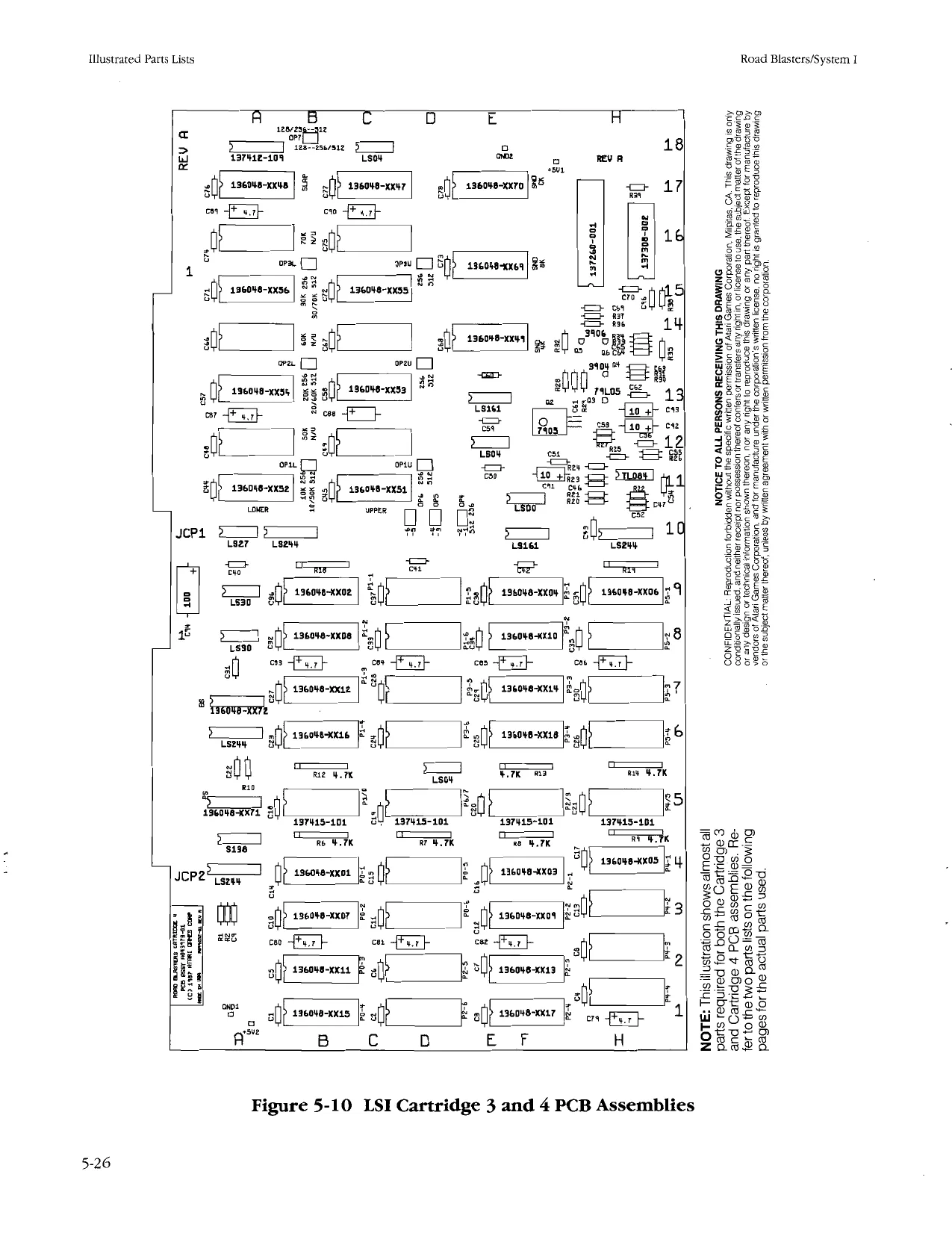
This page is a drawing, shown as the original scan.
Road Blasters/System I Illustrated Parts Lists
LSI Cartridge 3 PCB Assembly Parts List A043972-01 C
Desig- Desig-
| nator | Description | Part No. | nator | Description | Part No. |
| Integrated Circuits | 15N6E | IC, EPROM, 27128, 300 ns | 136048-1169 | ||
| 1B | IC, EPROM, 27256, 300 ns | 136048-1127 | 164, | IC, EPROM, 27256, 200 ns | 136048-1168 |
| ID | IC, EPROM, 27512, 300 ns | 136048-1117 | |||
| IF | IC, EPROM, 27256, 200 ns | 136048-1129 | 16C | IC, EPROM, 27256, 200 ns | 136048-1167 |
| 2B | IC, EPROM, 27256, 300 ns | 136048-1123 | 16F/H | I, Interface Adapter, 65224 | 137260-001 |
| 16H | IC, LPC, Voice Synthesis Processor, 5220C | _137308-002 | |||
| 2D | IC, EPROM, 27256, 300 ns | 136048-1133 | 17A | IC, EPROM, 27128, 200 ns | 136048-1148 |
| 2F | IC, EPROM, 27256, 300 ns | 136048-1125 | |||
| 3B | IC, EPROM, 27256, 300 ns | 136048-1119 | 17¢ | IC, EPROM, 27128, 200 ns | 136048-1147 |
| 3D | IC, EPROM, 27512, 300 ns | 136048-1115, | 17E | IC, EPROM, 27128, 300 ns | 136048-1179 |
| 18A | IC, SLAPSTIC | 13 7412-109 | |||
| 3F | IC, EPROM, 27256, 300 ns | 136048-1121 | 18C | IC, 741804 | 37-741804 |
| 4A | IC, 7418244 | 37-7418244 | |||
| 4B | IC, EPROM, 27256, 300 ns | 1360481101 | Capacitors | ||
| 4D | IC, EPROM, 27256, 300 ns | 136048-1131 | C1045 | Capacitor, .1 pF 50 V, Ceramic | 122002-104 |
| C46 | Capacitor, 22 pk, 25 V, Ceramic | 122004-224 | |||
| 4F | IC, EPROM, 27256, 300 ns | 136048-1103 | CAT | Capacitor, .0068 pF, 50 V, Ceramic | 122015-682 |
| 4H | IC, EPROM, 27256, 300 ns | 136048-1105 | C48-C52 | Capacitor, .1 pF, 50 V, Ceramic | 122002-104 |
| 516D | IC, 74L804 | 37-741804 | |||
| 5A | IC, PROM, 748473 | 136048-1173 | C53 | Capacitor, 22 wl, 25 V, Ceramic | 122004-224 |
| C54 | Capacitor, .1 lE, 50 V, Ceramic | 122002-104 | |||
| 5B, 5D, 5F, 5H IC, SLAGS | 137415-101 | C55 | Capacitor, .22 wR, 25 V, Ceramic | 122004-224 | |
| 67a, | IC, PROM, 748472 | 136048-1175 | C56 | Capacitor, .0039 uF, 50 V, Ceramic | 122015:392 |
| 6A | IC, 7418244 | 37-74LS244 | |||
| 6B | IC, EPROM, 27256, 300 ns | 136048-1128 | €57-C62_—_ | Capacitor, 1 a, 50 V, Ceramic | 122002-104 |
| 663, | Capacitor, 0012 aE, 50 V, Ceramic | 122015-122 | |||
| 6D | IC, EPROM, 27512, 300 ns | 136048-1118 | C64 | Capacitor, .018 uF, 50 V, Ceramic | 122015-183 |
| OF | IC, EPROM, 27256, 300 ns | 136048-1130 | C65 | Capacitor, 100 pF, 100 V, Ceramic | 122016-101 |
| 7B | IC, EPROM, 27256, 300 ns | 136048-1124 | |||
| 7D | IC, BPROM, 27256, 300 ns | 136048-1134 | C66-C78 | Capacitor, .1 wF, 50 V, Ceramic | 122002-104 |
| C79-C90 | Capacitor, 4.7 uF, 50 V, Electrolytic | 24500475 | |||
| TF | IC, EPROM, 27256, 300 ns | 136048-1126 | C91-C93._———Capacitor, 10 wf, 35 V, Electrolytic | 24350106 | |
| 8A | IC, 741830 | 37-741830 | 094 | Capacitor, 100 ak, 25 V, Electrolytic | 24250107 |
| 8B | IC, EPROM, 27256, 300 ns | 136048-1120 | C96 | Capacitor, 0027 uF, 50 V, Ceramic | 122015-272 |
| 8D | IC, EPROM, 27512, 300 ns | 136048.1116 |
Transistors
| 8F | IC, EPROM, 27256, 300 ns | 136048-1122 | @ | IC, 79105 (Acceptable substitute is part no. | 37-79L05 |
| 9A | IC, 741830 | 37-74LS30 | 37-7905) | ||
| 9B | IC, EPROM, 27256, 300 ns | 136048-1102 | fort | ‘Transistor, 2N3904 | 34-2N3904 |
| 9D | IC, EPROM, 27256, 300 ns | 136048-1132 | 95, 6 | ‘Transistor, 2N3906 | 33-2N3906 |
| oF | IC, EPROM, 27556, 300 ns | 136048-1104 | Resistors | ||
| oH | IC, EPROM, 27256, 300 ns | 136048-1106 | RI | Resistor, 330Q, +5%, 4 W | 110000-331 |
| 10/1F | IC, 741800 | 37-74L800 | R2 | Resistor, 2202, £5%, 4 W | 110000-221 |
| 108 | IC, 741827 | 37-74L827 | R3,R4 | Resistor, 4.7 KQ, £5%, 4 W | 1100-472 |
| RS | Resistor, 2.4KQ, +5%, & W | 110000-242 | |||
| 10B | IC, 7415244 | 37-74L8244 | |||
| 10F | IC, 74,8161 | 37-7415161 | Resistor, 4.7K x90, 25%, )4 W, SIP | 118010472 | |
| at | IC, BPROM, 27256, 200 ns | 136048-1158 | (10-Pin) | ||
| uct | IC, EPROM, 27256, 200 ns | 136048-1157 | Resistor, 2.4KQ, +5%, 4 W | 110000-242 |
Resistor, 4.7K x90, +5%, JW, SIP 118010-472
| iH | IC, Op Amp, TLOB4 | 37-347 | (10-Pin) | ||||
| 2A | IC, EPROM, 27256, 200 ns | 136048-1164 | RIS-RI7——_—Resistor, 2.4KQ, +5%, 4 W | 110000-242 | |||
| RBC | IC, EPROM, 27256, 200 ns | 136048-1163 | |||||
| RE | IC, 74L804 | 37-741804 | R20 | Resistor, 10KQ, + 5%, & W | 110000-103 | ||
| R21 | Resistor, 5.6KQ, +5%, & W | 110000-562 | |||||
| 13a* | 1C, EPROM, 27256, 200 ns | 136048-1160 | R22 | Resistor, 10 KQ, +5%, & W | 110000-103 | ||
| 13C* | IC, EPROM, 27256, 200 ns | 136048-1159 | R23, | Resistor, 43 KQ, £5%, & W | 110000-433 | ||
| BE | 1C, 7418161 | 37-7418161 | . | ||||
| 148 | IC, EPROM, 27256, 200 ns | 136048-1166 | R24,R25 | Resistor, 20KQ, | 5%, | W | 110000-203 |
| R26 | Resistor, 43 KQ, £5%, i W | 110000-433 | |||||
| 14C | IC, EPROM, 27256, 200 ns | 136048-1165 | R27 | Resistor, 1.8 KQ, +5%, & W | 110000-182 | ||
| 14E | IC, EPROM, 27128, 300 ns | 136048-1149 | R28 | Resistor, 3.3 KQ, +5%, MW | 110000332 |
"The part number for the German version of this IC is identical except that the second digit of the suffix is a "2" instead of a “1” (4.e., 136048-x2xx) 5-27
Illustrated Parts Lists Road Blasters/System I
LSI Cartridge 3 PCB Assembly Parts List, Continued Desig- Desig-
| nator | Description | Part No. | nator | Description | Part No. |
| R29 | Resistor, 3902, +5%, 4 W | 110000-391 | Miscellaneous | ||
| R30 | Resistor, 56KQ, +5%, 4 W | 110000-563 | +5V1, +5V2_ Test Point | 179051-002 | |
| R31 | Resistor, 12 KO, +5%, 14 W | 110000-123 | GNDI,GND2_ Test Point | 179051-002 | |
| R32 | Resistor, 1 KQ, +5%, 4 W | 110000-102 | OPIL-OP3L | Conn, 6 Ckt, Fidr, .100 Ctr | 179177-006 |
OP1v-OP3U
| R33 | Resistor, 10KQ, +5%, & W | 116000-103 | ||||
| R34 | Resistor, | 3.3KQ, +5%, la W | 110000-332 | OPIL-OP3L | Connector, Rept, 2CKT | 179178-002 |
| R35 | Resistor, 8.2 KQ, 25%, 4 W | 110000822 | OPIU-OP3U | |||
| R36 | Resistor, 3.3 K, £5%, 4M W | 110000-332 | Socket, 14-Pin | 79-40C14 |
Socket, 1¢Pin 79-42C16
| R37 | Resistor, 10 KO, +5%, % W | 110000-103 | |||
| R38 | Resistor, | 3.9 KO, +5%, 4 W | 110000-392 | Socket, 20-Pin | 79-42C20 |
| R39 | Resistor, 10KQ, +5%, & W | 110000-103 | Socket, 28-Pin | 79-42C28 | |
| R40 | Resistor, 4.7K, +5%, 4 W | 110000-472 | Socket, 40-Pin | 79-42C40 |
LSI Cartridge 4 PCB Assembly Parts List A043973-01 C Desig: Desig-
| nator | Description | Part No. | naior | Description | Part No. |
| Integrated Circuits | lat | IC, EPROM, 27512, 200 ns | 136048-1152 | ||
| 1B | IC, EPROM, 27512, 300 ns | 136048-1115 | 1ic* | IC, EPROM, 27512, 200 ns | 136048-1151 |
| 1F | JC, EPROM, 27512, 300 ns | 136048-1117 | 1H | IC, Op Amp, TL084 | 37347 |
| 2B | IC, EPROM, 27512, 300 ns | 136048-1411 | YE | IC, 741804 | 37-741.804 |
| aE | IC, EPROM, 27512, 300 ns | 136048-1113, | |||
| 13a" | IC, EPROM, 27512, 200 ns | 136048-1154 | |||
| 3B | IC, EPROM, 27512, 300 ns | 136048-1107 | BC | IC, EPROM, 27512, 200 ns | 136048-1153 |
| 3F | IC, EPROM, 27512, 300 ns | 136048-1109 | BE | IC, 7418161 | 37-74LS161 |
| 4i58 | IC, 745138 | 137174-001 | 14E. | IC, EPROM, 27128, 300 ns | 136048-1149 |
| 48 | IC, 7418244 | 37-7418244 | |||
| 1SN6E | IC, EPROM, 27128, 300 ns | 136048-1169 | |||
| 4B | IC, EPROM, 27256, 300 ns | 136048-1101 | 164 | IC, EPROM, 27256, 200 ns | 136048.1168 |
| 4F | IC, EPROM, 27256, 300 ns | 136048-1103 | 16C | IC, EPROM, 27256, 200 ns | 136048-1.67 |
| 4 | IC, EPROM, 27250, 300.ns | 136048-1105 | 16R/H | IC, Interface Adapter, 65224 | 137260-001 |
| 516D | IC, 741804 | 37-741804 | |||
| 16H | IC, LPC, Voice Synthesis Processor, 5220C | _-137308-002 | |||
| 5A | IC, PROM, 748473 | 136048-1171 | 1A | IC, EPROM, 27128, 200 ns | 136048-1148 |
| 5B, 5D, SE 5H IC, SLAGS | 137415-101 | 1c | IC, EPROM, 27128, 200 ns | 136048-1147 | |
| 6I7A | IC, PROM, 748472 | 136048-1172 | 17E | IC, EPROM, 27128, 300 ns | 136048-1170 |
| 6A | IC, 7418244 | 37-74L8244 | |||
| 18A | IC, SLAPSTIC | 137412-109 | |||
| 6B | IC, EPROM, 27512, 300 ns | 136048-1116 | 18C | IC, 741804 | 37-741804 |
| or | 1C, EPROM, 27512, 300 ns | 136048-1118 | |||
| 7B | IC, EPROM, 27512, 300 ns | 136048-1112 | Capacitors | ||
| TF | IC, EPROM, 27512, 300 ns | 136048-1114 | ci-C45, | Capacitor, .1 nF, 50 V, Ceramic | 122002:104 |
| C46 | Capacitor, .22 pF, 25 V, Ceramic | 122004-224 | |||
| 8A | IC, 74L830 | 37-741830 | a7 | Capacitor, .0068 uF, 50 V, Ceramic | 122015-682 |
| 8B | IC, EPROM, 27512, 300 ns | 136048-1108 | C48-C52—_ | Capacitor, .1 wk, 50 V, Ceramic | 122002-104 |
| 8F | IC, EPROM, 27512, 300 ns | 136048-1110 | |||
| 9A | IC, 74.830 | 37-741830 | 53 | Capacitor, 22 wR, 25 V, Ceramic | 122004224 |
| 54 | Capacitor, .1 uF, 50 V, Ceramic | 122002-104 | |||
| 9B | IC, EPROM, 27256, 300 ns | 1360481102 | C55 | Capacitor, 22 4, 25 V, Ceramic | 122004-224 |
| OF | IC, EPROM, 27256, 300 ns | 136048-1104 | C56 | Capacitor, .0039 F, 50 V, Ceramic | 122015-392 |
| oH | IC, EPROM, 27256, 300 ns | 136048-1106 | |||
| 10/11F | IC, 741800 | 37-74LS00 | C57-C62—— | Capacitor, .1 pF, 50 V, Ceramic | 422002-104 |
| C63 | Capacitor, .0012 pi, 50V, Ceramic | 122015-122 | |||
| 10 | IC, 741827 | 37-741827 | C64 | Capacitor, .018 nF, 50 V, Ceramic | 122015-183 |
| 10B | IC, 7418244 | 37-74LS244 | 065, | Capacitor, 100 pE, 100 V, Ceramic | 122016-101 |
| 10F | IC, 7418161 | 37-74L8161 | |||
| 10H | IC, 7418244 | 37-7418244 |
“The part number for the German version of this IC is identical except that the secontd digit of the suffix is a “2” instead of 4 “1” (i.e., 136048-x2200. 5-28
Road Blasters/System | Illustrated Parts Lists
ISI Cartridge 4 PCB Assembly Parts List, Continued Desig- Desig-
| nator | Description | Part No, | nator | Description | Part No. | |
| ©66-C78 | Capacitor, .1 | 50 V, Ceramic | 122002-104 | R28 | Resistor, 3.3K@, +5%, % W | 110000332 |
| C79-C90 | Capacitor, 4.7 uF, 50 V, Electrolytic | 24-500475, | R29 | Resistor, 3909, +5%, 4 W | 110000-391 | |
| C91-C93_——_Capacitor, 10 aR, 35 V, Ekectrolytic | 24350106 | R30 | Resistor, 56KQ, 45%, & W | 110000-563 | ||
| C94 | Capacitor, 100 uF, 25 V, Electrolytic | 24-250107, | R31 | Resistor, 12 KQ, +5%, 4 W | 110000-123 | |
| C96, | Capacitor, .0027 wF, 50 V, Ceramic | 122015-272 | ||||
| R32 | Resistor, 1 KQ, +5%, 4 W | 110000-i02 | ||||
| ‘Transistors | R33 | Resistor, 10KQ, £5%, 4 W | 110000-103 | |||
| @ | IC, 79L05 (Acceptable substitute is part no. | 37-79L05 | R34 | Resistor, 3.3K, +5%, 1 W | 110900332 | |
| 37-7905) | R35 | Resistor, 8.2K, +5%, & W | 110000822 | |||
| or | Transistor, 2N3904 | 34-2N3904 | ||||
| Q5,06 | Transistor, 2N3906 | 33-2N3906 | R36 | Resistor, 3.3 KO, +5%, 4 W | 110000-332 | |
| R37 | Resistor, 10 KQ, +5%, % W | 110000-103 | ||||
| Resistors | R38 | Resistor, 3.9 KQ, | 5%, 4 W | 110000-392 | ||
| RI | Resistor, 3300, +5%, 4 W | 110000-331 | R39 | Resistor, 10K@, +5%, 4 W | 110000-103 | |
| R2 | Resistor, 2200, +5%, 4 W | 110000-221 | ||||
| RO-RO | Resistor, 4.7K x 90, +5%, % W, SIP | 118010-472 | Miscellaneous | |||
| (10-Pin) | GND, | Test Point | 179051-001 | |||
| Rio | Resistor, | 24K@, 45%, MW | 110000-242 | GND2 |
+5V1, +5V2
| R12-R14 | Resistor, 4.7K x9, +5%, 4 W, SIP | 118010-472 | OP4-OP6 | Conn, 6 Ckt, Hdr, .L00 Ctr | 179177-006 |
(10-Pin) OPIL-OP3L
| R20 | Resistor, 10 KQ, +5%, 4 W | 110000-103, | OP1U-OP3U | ||
| R21 | Resistor, 5.6 KQ, 5%, 4 W | 110000-562 | |||
| R22 | Resistor, 10 KQ, 45%, 4 W | 110000-103 | OP4-OP6 | Conn, Rept, 2 Ckt | 179178-001 |
OPIL-OP3L
| R23 | Resistor, 43 KO, +5%, 4 W | 110000-433 | OPIU-OP3U | |
| R24,R25 | Resistor, 20KQ, +5%, 4 W | 110000-203 | ||
| R26 | Resistor, 43 KQ, +5%, 4 W | 110000-433 | Socket, 14-Pin | 79-42C14 |
| R27 | Resistor, L.8KD, +5%, 4 W | 110000-182 | Socket, 20-Pin | 79-42C20 |
Socket, 28-Pin 79-42C28 Socket, 40-Pin 79-42C40
5-29
Illustrated Parts Lists
JOU "02/04 UMOUS YOYELLIOIUfeoIUYDEI 10 UBSep Aue 19 08704) UORSSess0d 40U jdiG091 J8yJBU PUB ‘PENss! A(UONPUOD ‘yim queue .Be uojues Aq ssojun yoaseu) sayew Yoakgns a4) 10 Jo UoISSIUed UMM Sypads ain nou YPPIIO} LORONPUIGEY “WILNSOLINOO ‘4g epun armperue 105 oue ‘uotEIodog SUED Uely SoD
‘sonpoxdes oF wl SHJSUEL 10 Sk Jo, door au ued A820 BoMe Sa IMEI 2) 0 JONEU JookgS Oty '26N O} @SUBOH 10 "U! Avo si Busneup Siu "WO 'Seydyyy ‘vogeiodi09 sewed veIy ‘Bua ‘ONIVUG SIH DNIAIZO3¥ SNOSHAd TI O1 3OLLON ‘yORR:0ds09 849 WO} UORSIUEd LOR 10 i OU 'e8uaOH UaHUM 8, Lonez0dL09
1p 844 eonpoide) 0} pawesB s1 4B OU amc ‘enpeyuews fa onoen
5-30 Road Blasters/System I
cma (Pe aN Use these pads for C17 & C18 Use these pads for C17-A & C18-A.
Figure 5-11 Audio II PCB Assembly A043661-02 D
Road Blasters/System I Illustrated Parts Lists
Audio II PCB Assembly Parts List
| Designator | Description | Part No. |
Capacitors
| C1-C5 | 3300 wE, 25 V Radial Electrolytic Capacitor | 123003-338 |
| C6-C12 | .1 WE, 50 V Ceramic Capacitor | 122002-104 |
| C13, C14 | 22 uF, 35 V Electrolytic Capacitor | 24-350226 |
| C15-C18 | .22 uF, 25 V Ceramic Capacitor | 122006-224 |
| C19, C20 | .001 uF, 50 V Ceramic Capacitor | 122002-102 |
| 21-C23, | .1 wE, 50 V Ceramic Capacitor | 122002-104 |
Diodes
| CR1-CR4 | Type-1N5401 Diode | 31-1N5401 |
| CR5-CR10 | Type-1N4001 Diode | 31-1N4001 |
| CRI3 | ‘Type-1N4002 Diode | 31-1N4002 |
Connectors
| JACDC | Key 6, 9 Ckt., .156-Inch Ctr. Header Connector | 179213-009 |
| jJaux | Key 6, 9 Ckt., .156-Inch Ctr. Header Connector | 179213-009 |
| JCDL | 2 Ckt., .156-Inch Ctr. Header Connector | 179213-002 |
| JSPK | Key 3, 6 Ckt., .156-Inch Ctr, Header Connector | 179213-006 |
Integrated Circuits
| Q1, Q2 | ‘TypeTDA-2030 Amplifier | 137301-001 |
| @ | Standup Type-7812 Integrated Circuit | 37-7812 |
Resistors
| RI | 10 kQ, Dual Horizontal Pot Resistor | 119011-103, |
| R3 | 109, £5%, 4 W Resistor | 110000-100 |
| R4-R7 | 22kQ, +5%, %4 W Resistor | 110000-223, |
| R8, RO | 10kQ, +5%, % W Resistor | 110000-103 |
| R10-R11 | 1kQ, 45%, %4 W Resistor | 110000-102 |
| R12, R13 | 10, +5%, % W Resistor | 110000-010 |
| R14, R17 | OG, 45%, % W Resistor | 110005-001 |
7 Miscellaneous
| sw | SPDT Miniature Slide Self-Test Switch | 69-004 |
Type-TDA-2030 Heat Sink 178190-032 #0-32 x %-Inch Cross-Recessed Pan-Head Screw 72-1606 #6-32 Nut/Washer Assembly 75-99516
Thermal Compound 78-16001 Hot Melt Adhesive 106006-001 Test Point 179051-001
This page carries no recoverable text. It is a drawing or a photograph. See the original scan.
Chapter 6
Kit Installation
” Your Road Blasters™ game uses the System [™ cabinet designed to accept the necessary hardware to easily convert the cabinet into a variety of games. This chapter contains information that applies to those parts of your existing System I cabinet that are added or replaced to convert the cabinet to a Road Blasters game. (See Figure 6-1.) The conversion instructions include: (1) replacing the attraction film, control panel, and game Cartridge Printed-Circuit Board (PCB); (2) installing two bolts to strengthen the control panel assembly; (3) installing the foot pedal assembly and installing the cabinet control harness assembly, and
- cleaning the video display. See Figure 6-1 for the locations of the parts of the System I cabinet that are replaced, installed, and cleaned. Wiring and schematic diagrams for the Road Blasters game are contained in the Schematic Package Supplement (SP-298) included with your game.
Kit Parts Inventory
The assemblies listed in Table 6-1 are included in the Road Blasters Conversion Kit. Refer to Chapter 5, Illustrated Parts List, for a description of the component parts comprising the control panel, foot pedal, and LSI Cartridge PCB listed in Table 6-1.
Tools Required
The only tools required to perform a complete Road Blasters conversion are: Phillips screwdriver, 4-inch hex driver, <-inch nut driver, /<-inch open-end wrench, awl, hammer, drill, {<-inch drill bit, 34-inch drill bit, 1%-inch spade bit, and Scotch tape (or stapler). (A %4-inch wrench is also required if your game has a vertically mounted video display.)
Kit Installation Road Blasters/System I
Attraction Film
Controi Panel Assy Cabinet Control! Harness (includes RTC Steering Control)
a
Product ID Label (not shown)
Part of Cabinet Control Harness Assy
Cartridge PCB Assy
Self-Test Label Foot Pedal Assy {not shown)
Figure 6-1 Kit Part Locations
6-2
Road Blasters/System I
Table 6-1 Road Blasters Kit Parts Inventory A043956-xx
Part No. Quantity Description
| A043825-01 | 1 | Foot Pedal Assembly |
| A043941-01 | 1 | Cabinet Control Harness Assem- |
bly
| A043957-02 | 1 | Control Panel Assembly |
| A043972-01 | 1 | LSI Cartridge 3 PCB Assembly |
or or
| A043973-01 | 1 | LSI Cartridge 4 PCB Assembly |
| 75-010F | 2 | #10 Black Flat Washer |
| 75-0158 | 4 | #¥%4-Inch Flat Washer |
| 75-050B | 2 | #10 Black Internal Tooth Washer |
| 82-8120B | 2 | #10-24 x 1%4-Inch Black Button- |
Head Hex-Socket Machine Screw
| 038158-01 | 1 | Product Identification Label— |
Non-UL (042465-01 #)
| 043961-01 | 1 | Foot Pedal Mounting Template |
| 043961-02 | 1 | Control Panel Mounting Tem- |
plate
| 044324-01 | 1 | Contest Marquee |
| 044392-01 | 1 | Attraction Film with Graphics |
| 177010-244 | 4 | #%4-20 Hex Lock Nut |
| TM-298 | 1 | Operators Manual |
| SP-298 | 1 | Schematic Package Supplement |
| ST-298, | 1 | Self-Test Label |
Conversion Instructions
A WARNING A To avoid electrical shock, unplug the game before performing the conversion procedures.
The following procedures are arranged in the sequence recommended for performing the game conversion. The parts of your cabinet that are affected by the conversion are removed first and then replaced by the new Road Blasters kit parts.
Replace the Attraction Film Perform the following procedure to remove/replace the existing attraction film with the Road Blasters attraction film. (See Figure 6-2). Kit Installation
Retainer
Attraction Film
Attraction Shield ?
Figure 6-2 Attraction Film Replacement
- Turn off the game power.
- Using a inch hex driver, remove the three screws and washers holding the upper retainer to the top of the cabinet.
- Grasp the top edge of the existing attraction film behind the attraction shield and slide it up to remove.
. Install the Road Blasters attraction film. Make sure the film is fully inserted into the bottom slot. #
- Remount the upper retainer.
Remove the Control Panel
Perform the following procedure to remove/replace the existing control panel with the Road Blasters control panel. (See Figure 6-3).
- Unlock and open the coin door on the front of the cabinet.
- Carefully reach through the coin door opening and release the spring-draw latch located under the control panel on the right side of the cabinet.
3, Unlock and remove the front access panel. 4, Reach through the front access panel opening and disconnect the control panel harness from the top of the Main PCB Assembly.
- Carefully reach up under the top of the front access panel opening and release the spring-draw latch located under the control panel on the left side of the cabinet.
- From underneath, push up on the front edge of the control panel to free the panel from the slot in the cabinet.
- Carefully lift the control panel from the cabinet.
Kit Installation
Control Panel
Front Access Panel
Foot Pedal
Py Road Blasters/System I
Coin Door
|«—— Foot Pedal Template
Figure 6-3 Control Panel and Foot Pedal Installation
- Disconnect the green ground wire from the control panel harness,
Clean the Video Display Glass
Static electricity attracts dust to the video display glass and can cause the video image to grey out, making the screen colors appear faded. In order to prevent this from happening, the video display glass must be cleaned. Perform the following procedure to clean the display glass.
- Using a %;-inch hex driver, remove the two screws holding the lower retainer to the cabinet.
- Grasp the display shield on the bottom edge and gently pull it out about one half inch from the cabinet.
- Gently lower the display shield to free the top edge from under the speaker grille.
- Using a glass cleaner, clean the display glass and the monitor screen. Be sure to avoid spraying the bezel.
- Replace the display shield in the reverse order of removal.
Install the Cabinet Control Harness
Perform the following procedure to install the cabinet control harness. (See Figure 6-1.)
- Remove the existing control harness.
- Plug the cabinet control harness connectors P102, P106, and P103 into the Main PCB at J102, J106, and J103, matching keyed connectors with keyed PCB headers.
- Connect the two mating green ground wires to each other.
Install the Control Panel Bolts
Perform the following procedure to install two control panel bolts to strengthen the control panel. (See Figure 63.) 1, Remove the control panel as described earlier in this chapter.
- Remove the protective backing from the control panel mounting template (Atari part no. 043961-02).
- Align the side edges of the template along the inside edges of the cabinet side panel.
- With the template properly positioned, use an awl and hammer to make an indentation on the two cross marks shown on the template. Remove the template.
- Use a inch drill bit and drill a hole at each indentation.
- Plug the 12-position harness connector P24 into the control panel harness connector.
Road Blasters/System 1
- Install the Road Blasters control panel. (Be sure to securely fasten the two spring-draw latches under the control panel.) 7
- Insert a 14-inch black bolt, internal-tooth washer, and. flat washer into each hole and tighten with a }s-inch hex driver. (The bolts and washers are supplied with the kit.)
Install the Foot Pedal
The Road Blasters gatne uses a foot pedal. Perform the following procedure to install the foot pedal. (See Figure 63.) 1, Remove the protective backing from the foot pedal mounting template (Atari part no. 043961-01).
- Remove the two carriage bolts from the bottom right corner of the cabinet coin door panel, 3, Align the two holes of the template with the two holes in the bottom right corner of the cabinet coin door panel.
- With the template properly positioned, use an awl and hammer to make an indentation on the three cross marks shown on the template. Remove the template.
- Use a ¥-inch drill bit and drill a hole at each corner indentation.
- Use a 1%-inch spade bit and drill a hole at the center indentation.
- Insert the foot pedal harness assembly through the center hole.
- Insert the four bolts of the foot pedal assembly into the four corner holes.
9, Use a ,-inch nut driver to tighten the four lock nuts and flat washers of the bolts. (The nuts and washers ace supplied with the kit.)
- Connect the foot pedal harness to the cabinet control harness.
Replace the Cartridge PCB
Perform the following procedure to remove/replace the existing game Cartridge PCB and replace with the Road Blasters Cartridge PCB. (See Figure 6-1.)
- Turn the cabinet power off.
- Unlock and remove the front access panel from the cabinet.
- Turn the four thumbscrews that hold the existing Cartridge PCB to the ground plane. (Some System I games might have Phillips screws.) 4, Gently disconnect the Cartridge PCB from the Main PCB. Kit Installation.
- Connect the Road Blasters Cartridge PCB to the Main PCB. Make sure that the Cartridge PCB is fully inserted into the Main PCB edge connectors.
- Replace the four thumbscrews on the Cartridge PCB. See Figure 6-1 for the locations of the printed-circuit boards, In order for this game to comply with Federal Communications Commission regulations, these thumbscrews must be tight. The Cartridge PCB must be securely connected to the ground plane.
Install the Self-Test Label Staple or tape the Road Blasters Self-Test Label on the inside of the front access panel.
Install the Product Identification Label
Perform the following procedure to install the Road Blasters product identification label.
- Remove the protective backing from the Road Blasters product identification label.
- Place the Road Blasters product identification label over the existing product identification label on the back of the cabinet.
Inspect the Game Before applying power, perform the following inspection procedure. 1, Carefully check that the Road Blasters conversion kit parts have been properly installed. Check that the game Cartridge PCB has been properly installed. Make sure that the control-panel harness connector is tightly connected to the cabinet control harness connector, and that the spring draw latches under the control panel are securely fastened.
- Plug in the game power cord.
- Perform the self-test procedure as given in Chapter 2. If the self-test indicates that the video display requires adjustment, perform the adjustment procedures described in the video display manual included with your game. (If the roadway or car pictures are distorted, repeat the Cartridge PCB removal procedure.) 4, Be sure to reset the high score table and the accounting information, or game statistics. Refer to the procedure in Reset the High Score Table and the Accounting Information later in this chapter.
Kit Installation
- Close and lock the front access panel.
Setting the Coin and Game Options The Road Blasters coin and game options are set in the Self-Test Mode. Refer to Chapter 2 for the recommended settings and the procedure for setting the options.
Reset the High Score Table and the Accounting Information
The high score table and the accounting information, or game statistics, must be reset after completing the con-
6-6 Road Blasters/System I
version to ensure accurate game data. This information is displayed on the Accounting Information screen in the Self-Test Mode. (Refer to Accounting Information in Chapter 2.) Perform the following procedure to reset this information.
- Enter the Self-Test Mode by turning on the self-test switch, and press the thumb button on the RTC steering control until the Statistics screen is displayed.
- Press the foot pedal to reset the accounting information.
Road Blasters’
Coin Information and Game Statistics
Date: ___
Aux Coins Not used in Road Blasters game Left Coins Number of coins deposited in left coin mechanism Right Coins — Number of coins deposited in right coin mechanism. 1 Plyr Games Number of 1-player games Mins Played ‘Total time, in minutes, of all games played Mins Pwr Up Total time, in minutes, that the game has been turned on Aux Cntr 1 Highest rally achieved Aux Cntr 2 ‘Total number of times add-a-coin continuation used Aux Cntr 3 Number of games without a new entry into top four scores Error Count Number of EEPROM errors Avg. Game Time Average game time in seconds (including add-a-coin continuation games)
Histogram Information
Length of Number of Games That Reached Level Game in Seconds 1 2 3 4 5
0-59 60-89 90-119 120-149 150-179 _ 180-209 210-239 240-269 270-299 300-329 330-359 360-389 390-419 420-449 450-479 480-509 510-539 540 & up
High Score
Histogeam Levels 1-3: Number of games that started at the Rookie, Veteran, or Expert level, respectively. These are only games that were played without using the game continuation feature. Histogram Level 4: Number of games that ended on the original level for add-a-coin game continuation. Histogeam Level 5: Number of games that ended on a higher level after a game continuation
This page carries no recoverable text. It is a drawing or a photograph. See the original scan.
AC Alternating current; from zero it rises to a maximum positive level, then passes through zero again to a maximum negative level. ACTIVE STATE The true state of a signal. For example: The active state for START is low.
ADDRESS A value that identifies a specific location of data in memory; normally expressed in hexadecimal notation.
ANALOG Measurable in an absolute quantity (as opposed to on or off). Analog devices are volume controls, light dimmers, stereo amplifiers, etc. ANODE The positive (arrow) end of a diode. AMPLIFIER A device used to increase the strength of an applied signal. AMPLITUDE The maximum instantaneous value of a waveform pulse from zero. ASTABLE Having no normal state. An astable device will free-run or oscillate as long as operating voltage is applied. The oscillation frequency is usually controlled by external circuitry. AUXILIARY COIN SWITCH A momentary-contact pushbutton switch with a black cap located on the utility panel. The auxiliary coin switch adds credits to the game without activating a coin counter. BEZEL A cut, formed, or machined retention device, such as the conical device used to mount a pushbutton switch to a control panel, or the formed device used to frame the video display screen. BIDIRECTIONAL Able to send or receive data on the same line (e.g., the data bus of a microprocessor). BINARY A number system that expresses all values by using two digits (0 and 1). BIT Abinary digit; expressed as 1 or 0. BLANKING Turning off the beam on a cathode-ray tube during retrace. BLOCK DIAGRAM A drawing in which functional circuitry units are represented by blocks. Very useful during initial troubleshooting. BUFFER
- An isolating circuit designed to eliminate the reaction of a driven circuit on the circuits driving it (e.g., a buffer amplifier).
- A device used to supply additional drive capability. BUS An electrical path over which information is transferred from any of several sources to any of several destinations. CAPACITOR A device capable of storing electrical energy. A capacitor blocks the flow of DC current while allowing AC current to pass. CATHODE The negative end of a diode. CHIP An integrated circuit comprising many circuits on a single wafer slice. CLOCK A repetitive timing signal for synchronizing system functions. COINCIDENCE Occurring at the same time. COIN COUNTER A G-digit electromechanical device that counts the coins inserted in the coin mechanism(s). COIN MECHANISM A device on the inside of the coin door that inspects the coin to determine if the correct coin has been inserted.
COMPLEMENTARY Having opposite states, such as the outputs of a flip-flop. COMPOSITE SYNC Horizontal and vertical synchronization pulses that are bused together into a single signal. This signal provides the timing necessary to keep the display in synchronization with the game circuitry. COMPOSITE VIDEO Complete video signal from the game system to drive the display circuitry, usually comprising H SYNC, V SYNC, and the video.
Glossary
CREDIT One play for one person based on the game switch settings. cRT Cathode-ray tube. DATA General term for the numbers, letters, and symbols that serve as input for device processing. DARLINGTON A two-transistor amplifier that provides extremely high gain. DC Direct current, meaning current flowing in one direction and of a fixed value.
DEFLECTION YOKE Electromagnetic coils around the neck of a cathode-ray tube. One set of coils deflects the electron beam horizontally and the other set deflects the beam vertically. DIAGNOSTICS A programmed routine for checking circuitry. For example: the self-test is a diagnostic routine. DIODE A semiconductor device that conducts, in only one direction. DISCRETE Non-integrated components, such as resistors, Capacitors, and transistors. DMA Direct memory access. DMA is a process of accessing memory that bypasses the microprocessor logic. DMA is normally used for transferring data between the input/output ports and memory. DOWN TIME The period during which a game is malfunctioning or not operating correctly due to machine failure.
EAROM Electrically alterable read-only memory (see ROM). The EAROM is amemory that can be changed by applying high voltage. EPROM Erasable programmable read-only memory (see ROM). FLYBACK A step-up transformer used in a display to provide the high voltage.
GATE 1, A circuit with one output that responds only when a certain combination of pulses is present at the inputs.
- A circuit in which one signal switches another signal on and off.
- To control the passage of a pulse or signal. HARNESS A prefabricated assembly of insulated wires and terminals ready to be attached to a piece of equipment. HEXADECIMAL A number system using the equivalent of the decimal number 16 as a base. The symbols 0-9 and A-F are usually used. HISTOGRAM Aspecial type of bar graph that shows how quantities are distributed. Histograms are included in the self-test of most Atari games, and typicaliy show how long players play that game. Ic Integrated circuit. An electronic circuit in which all elements and the connections are made in or on a single semiconductor substraie. See also chip. IMPLODE ‘To burst inward; the inward collapse of a vacuum tube. vO Input/Output. IRQ Interrupt request. IRQ is a control signal to the microprocessor that is generated. by external logic. This signal tells the microprocessor that external logic needs attention. Depending on the program, the processor may or may not respond. LED The abbreviation for a light-emitting diode. LOCKOUT COIL Directs coins into the coin return box when there is no power to the game. LOGIC STATE The binary (1 or 0) value at the node of a logic element or integrated circuit during a particular time. Also called the logic level. The list below shows the voltage levels corresponding to the logic states (levels) in a TTL system. Logic 0, Low = 0 VDC to +0.8 VDC Grey Area (Tri-State Level) = +0.8 VDC to +2.4 VDC Logic 1, High = +2.4VDC to +5 VDC MULTIPLEXER A device that takes several low-speed inputs and combines them into one highspeed data stream for simultaneous transmission on a single line. NMI Non-maskable interrupt. NMI is a request for service by the microprocessor from external logic. The microprocessor cannot ignore this interrupt request. PAGE A subsection of memory. A read-only memory device (sce ROM) is broken into discrete blocks of data. These blocks are called pages. Each block has X number of bytes. PCB ‘The abbreviation for a printed-circuit board.
PHOTOTRANSISTOR A transistor that is activated by an external light source, POTENTIOMETER
- A resistor that has a continuously moving contact which is generally mounted on a moving shaft. Used chiefly as a voltage divider. Also called a pot (slang).
- An instrument for measuring a voltage by balancing it against a known voitage. RAM Random-access memory. A device for the temporary storage of data. RASTER-SCAN DISPLAY A display system whereby images are displayed by continuously scanning the cathode-ray tube horizontally and vertically with an electron beam. The display system controls the intensity of the electron beam. RETRACE Ina raster-scan display, retrace is the time during which the cathode-ray tube electron beam is resetting either from tight to left or from bottom to top. RESISTOR A device designed to have a definite amount of resistance. Used in circuits to limit current flow or to provide a voltage drop. ROM Read-only memory. A device for the permanent storage of data. SIGNATURE ANALYSIS A process of isolating digital logic faults at the component level by means of special test equipment called signature analyzers, Basically, signature analyzers (eg, the ATARI® CAT Box) convert lengthy bit streams into four-digit hexadecimal signatures. The signature read by the analyzer at each circuit node is then compared with the known good signature for that node. This process continues until a fault is located. TROUBLESHOOT The process of locating and repairing a fault. VECTOR A line segment drawn between specific Xand Y coordinates on a cathode-ray tube.
WATCHDOG A counter circuit designed to protect the microprocessor from self-destruction if a program malfunction occurs. If a malfunction does occur, the counter applies continuous pulses to the reset line of the microprocessor, which causes the microprocessor to keep resetting. X-Y DISPLAY A display system whereby images are displayed with vectors. ZENER DIODE Aspecial diode used as a regulator. Its main characteristic is breaking down at a specified reverse-bias (Zener) voltage.
Warranty
Seller warrants that its printed-circuit boards and parts thereon are free from defects in material and workmanship under normal use and service for a period of ninety (90) days from date of shipment. Seller warrants that its video displays and laser video disc players (in games supplied with displays and video-disc players) are free from defects in material and workmanship under normal use and service for a period of thirty (30) days from date of shipment. None of the Seller's other products or parts thereof are warranted. If the products described in this manual fail to conform to this warranty, Seller's sole liability shall be, at its option, to repair, replace, or credit Buyer's account for such products which are returned to Seller during said warranty period, provided:
- Seller is promptly notified in writing upon discovery by Buyer that said products are defective;
- Such products are returned prepaid to Seller's plant; and
- Seller's examination of said products discloses to Seller's satisfaction that such alleged defects existed and were not caused by accident, misuse, neglect, alteration, improper repair, installation, or improper testing. In no event shall Seller be liable for loss of profits, loss of use, incidental or consequential damages. Except for any express warranty set forth in a written contract between Seller and Buyer which contract supersedes the terms herein, this warranty is expressed in lieu of all other warranties expressed or implied, including the implied warranties of merchantability and fitness for a particular purpose, and of all other obligations or liabilities on the Seller's part, and it neither assumes nor authorizes any other person to assume for the Seller any other liabilities in connection with the sale of products by Seller.
The use of any non-Atari parts may void your warranty, according to the terms of the warranty. The use of any non-Atari parts may also adversely affect the safety of your game and cause injury to you and others. Be very cautious in using non-Atari-supplied components with our games, in order to ensure your safety. Atari distributors are independent, being privately owned and operated. In their judgment they may sell parts or accessories other than Atari parts or accessories. Atari Games Corporation cannot be responsible for the quality, suitability or safety of any non-Atari part or any modification including labor which is performed by such distributor.
A.
ATARI
GAMES
Atari Games Corporation 675 Sycamore P.O. Box 361110 Milpitas, California 95035