Soccer DP-144-1st-01B
Atari Soccer (Atari, 1980) · Drawing Package · 1 pages · original scan
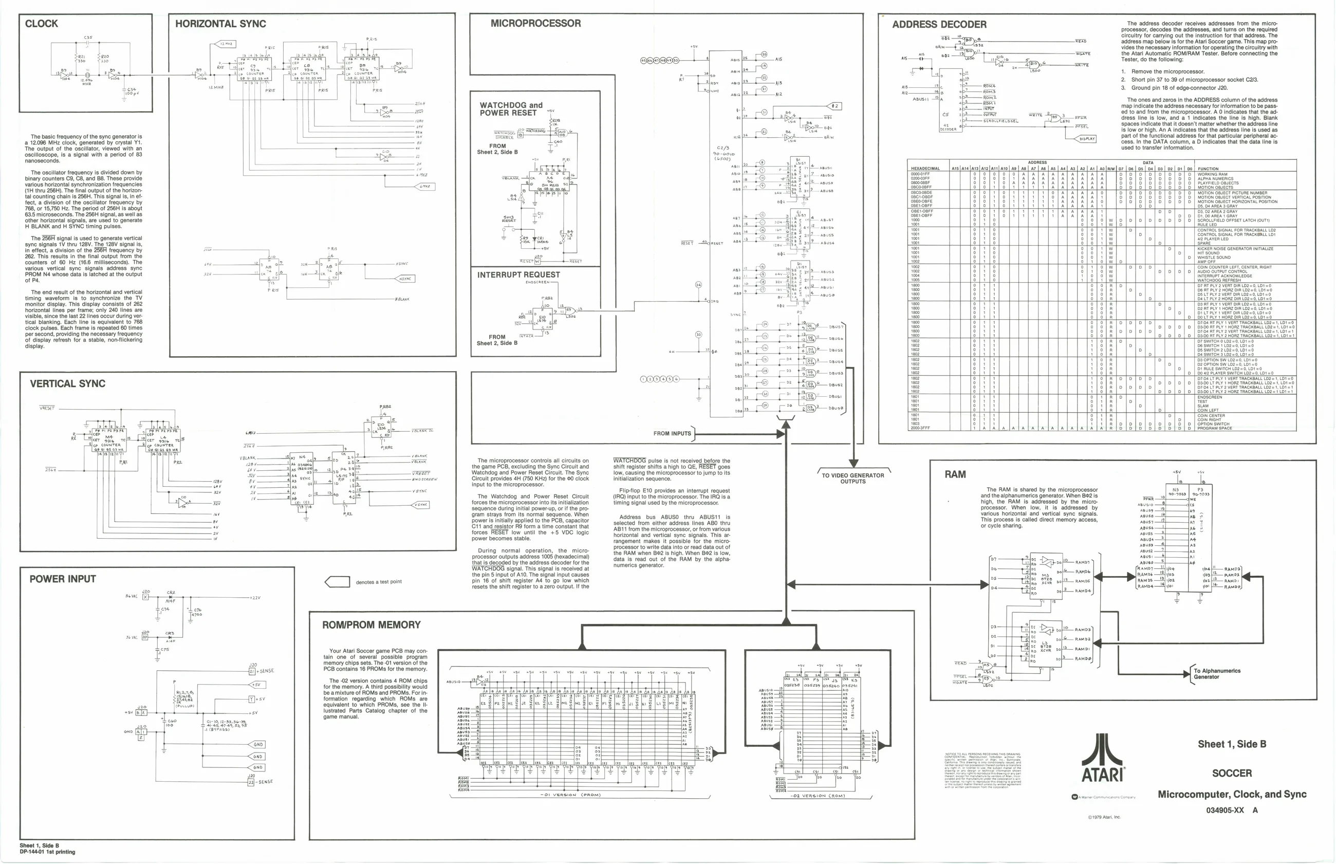
“The basic frequency ofthe sync generator is, ‘a 12.096 MHz clock, generated by crystal Y1. ‘The output of the oscillator, viewed with an ‘oscilloscope, is a signal with a period of 83 nanoseconds.
‘The oscillator frequency is divided down by binary counters C8, C3, and B8. These provide various horizontal synchronization frequencies. (1H thru 256H). The final output of the horizontal counting chain Is 256H. Ths signal i, in effect, a division of the oscillator frequency by 768, or 18,750 Hz. The period of 256H Is aboyt
tal counting chain Is 256H. Ths signal i, in ef 1635 microseconds. The 256H signal, as well as ‘The 256H signal is used to generate vertical
‘ther horizontal signals, are used to generate H BLANK and H SYNC timing pulses.
‘sync signals 1V thru 128V. The 128V signal In effect, a division of the 256H frequency by 262. This results in the final output from the Counters of 60 Hz (166 milliseconds). The Various vertical sync signals address. sync PROM Né whose datas ated a the output of
‘The ond result of the horizontal and vertical timing waveform is to synchronize the TV ‘monitor display. This display consists of 262 horizontal lines per frame; only 240 lines are visible, since the last 22 lines occur during ver. tical blanking. Each line is equivalent to 768
‘lock pulses. Each frame is repeated 60 times
er second, providing the necessary frequency
Of display refresh for a stable, non-flickering isplay.
VERTICAL SYNC
POWER INPUT HORIZONTAL SYNC
Le
Pee Ca
$f) - sins
‘ ROM/PROM MEMORY
‘Your Atari Soccer game PCB may contain one of several possible program ‘memory chips sets. The -01 version of the PCB contains 16 PROMS for the memory.
‘The -02 version contains 4 ROM chips for the memory. A third possibilty would bbe amixture of ROMs and PROMS. Forinformation regarding which ROMs are equivalent to which PROMS, see the IIlustated Parts Catalog chapter of the {game manual. MICROPROCESSOR
WATCHDOG and POWER RESET
INTERRUPT REQUEST
FROM wx Sheet 2, Side B
‘The microprocessor controls all circuits on the game PGB, excluding the Sync Circult and Watehdog and Power Reset Circult. The Syne Circuit provides 4H (750 KHz) for the #0 clock. Input to the microprocessor.
‘The Watchdog and Power Reset Circuit {forces the microprocessor into its initialization ‘sequence during initial power-up, or ifthe pro ‘gram strays from Its normal sequence. When power is initially applied to the PCB, capacitor ‘Git and resistor FO form a time constant that fore low until the +5 VDC logic ower becomes stable.
During normal operation, the micro: processor outputs address 1005 (hexadecimal) that is decoded by the address decoder for the WATCHDOG signal. This signal is received at the pin 5 input of A10. The signal input causes pin 16 of shift register A4 to go low which resets the shift register to a zero output. Ifthe ADDRESS DECODER
ce 538)"
FET —Sdeneer
14m. ‘The address decoder receives addresses from the microprocessor, decodes the addresses, and turns on the required Circuitry for carrying out the instruction for that address. The ‘address map below is for the Atari Soccer game. This map provides the necessary information for operating the circuitry with the Atari Automatic ROM/RAM Tester. Before connecting the Tester, do the following:
- Remove the microprocessor.
- Short pin 37 to 39 of microprocessor socket C23. 3, Ground pin 18 of edge-connector J20.
‘The ones and zeros in the ADDRESS column of the address ‘map indicate the address necessary for information to be pass- ‘0d to and from the microprocessor. A 0 indicates that the ad- ‘dress line is low, and a1 Indicates the line is high. Blank spaces indicate that it doesn't matter whether the address I Is low or high. An A indicates that the address line Is used as Part of the functional address for that particular peripheral acess Inthe DATA column aD inciates that the data line i
Funeron AAvneLb onieers tigwon caveats ‘orion oBiest veRmicAc POSTON Hoh Sect amon poston ceelvooels ceoloooels veefpoools leooaloooele sa)oaaabos ole aaleawalasesle eer 5 aofesecpoee hr zoponapoaole >oporapraole
°], SBitaOL NENA Fon TaAcALL ot Se SSS SS
° Bett pir 3 None bm be =0,01=,
Bobo nt pty wom Yeackeatl tooo, cbr=
FROM INPUTS
WATCHDOG pulse is not received before the shift register shifts ahigh to QE, RESET goes low, causing the microprocessor to jump to its Initialization sequence.
Fliptlop E10 provides an interrupt request (QR) input to the microprocessor. The IRQ is a timing signal used by the microprocessor.
‘Address bus ABUSO thru ABUSI1. is selected from either address lines ABO thru ‘AB11 from the microprocessor, or from various horizontal and vertical sync signals. This a rangement makes it possible for the microprocessor to write data into or read data out of the RAM when B82 is high. When B62 Is low, data is read out of the RAM by the alpha’ numerics generator.
=oi version Conon) Fees es ee ee ee ee en ee ee ee
TO VIDEO GENERATOR
The RAM is shared by the microprocessor ‘and the alphanumerics generator. When 842 is ihe RAM Is addressed by the microprocessor. When low, it is addressed by Yarious horizontal and’ vertical syne signals. This process is called direct memory access,
702 VERSION (ROM) AM Sheet 1, Side B ATARI SoCcen
eases Microcomputer, Clock, and Sync
034905-XX A