Asteroids DP-143-1st-02B
Asteroids (rev 4) (Atari, 1979) · Drawing Package · 1 pages · original scan
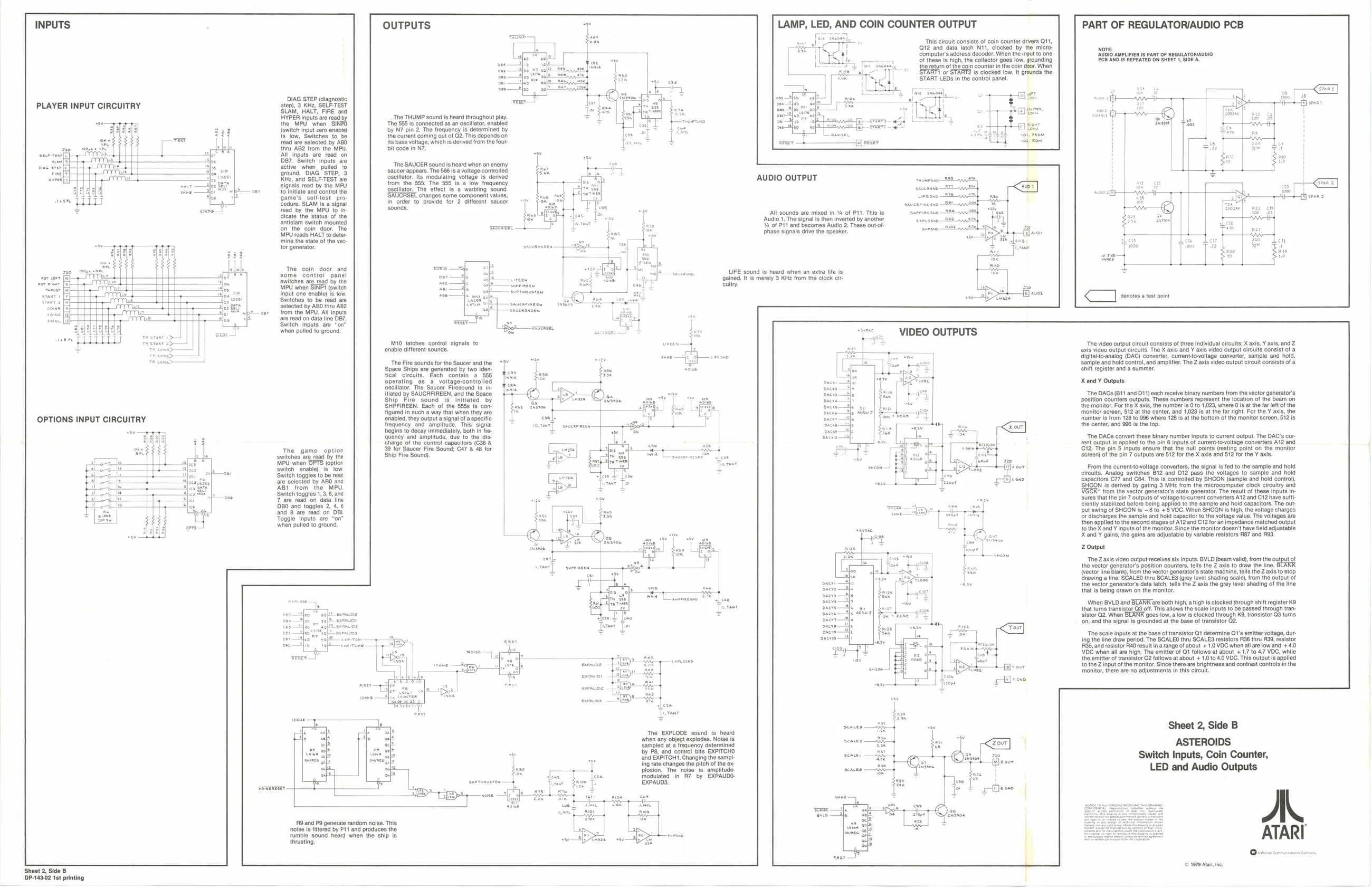
| INPUTS | OUTPUTS | LAMP, LED, AND COIN COUNTER OUTPUT | PART OF REGULATORIAUDIO PCB |
oe I 1s ‘This circuit consists of coin counter drvers Q11, eK TTT 12" and data latch Ni, clocked by the micro. cite ‘computer's address decoder. When the input to one AUDIO AMPLIFIER IS PART OF REGULATOR/AUDIO es Si eee sigh io collector gous tow rounding Sates E fheretum ote orn counter inthe coin door Whos «<4 START1 or START2 is clocked low, it grounds the a START LEDs in the control panel.
DIAG STEP (agnostic PLAYER INPUT CIRCUITRY step), 3 KHz, SELF-TEST Seah HALT FIRE ard =
| HYPER inputs are read by | ‘The THUMP sound is heard throughout play. | ae! |
| the MPU when SINFO | “Tne 85518 connected as an osclator, enabled | reer no |
{switch input foro nave) by NT pin 2 Te frequency fs ceternined by (Stow, Sutchoo tobe the cuent coming ot of Ge. Tas opens on fend af selecd by ABO Iatage voltage, which iscerived from te four 7 {iu AB2 om tno MPD, bit code nN
| me 2B | Ser | owich | Inoais we | ‘The SAUCER sounds heard when an enemy |
| finer | ground. | DIAG STEP, 3 | ‘saucer appears. The 566 is a voltage-controlled |
wveeafe Kile, and SELF-TEST ave oscillator. Its modulating voltage Is derived AUDIO OUTPUT
| (Gu; sad | SELTeST ae | from ine 5. Tho 385"1s'2 tow reguenoy |
| bey | elie idly | Geallate. Tho ettect l'a warling Sound |
game's self-test pro- ‘SAUCRSEL changes some component values, Geneie,seitieat ee iner to nove tor deen sce
| ual | Ge ae | : | ‘A sounds av mised In. | of PY This |
eae ieee ot a Audio he sgl then iwerted by another se canoes Wor Pit and tecornes Audio These out MPU reads Hate dtee have signals ave tn speaker nine te sat of the ws
| The: cain | doce sand | aaenaay, | LIFE sound is heard when an extra life is |
some control panel Switches are read by the Seen MPU when SINPI (switch nee Input one enable) is low. suerumusren Switches to be read are selected by ABO thru AB2 oer from the MPU. All inputs are read on data line OB7. Switen inputs are "on™ _ ‘when pulled to ground Lipo _exverer, rant > Teataar 2 M10 latches control signals to ph ‘enable different sounds. The Fire sounds for the Saucer andthe "3 ‘Space Ships are generated by two iden tical circuits. Each contain a 555 operating a6 a voltage-controlied
oscillator. The Saucer Firesound is in figured in such a way that when they are
Itlated by SAUCRFIREEN, and the Space Ship Fire sound is’ initiated by SHPFIREEN. Each of the 5558 is con-
| OPTIONS INPUT CIRCUITRY | enabled, they outputa signal of aspecitic | | | |
frequency and amplitude. This signal | ~ begins to decay immediately, both in tre ‘quency and amplitude, due'to the dis-
galned. It is merely 3 KHz from the clock cir
Cuity.
T ime A
“ps. VIDEO OUTPUTS ‘The video output circult consists of three individual circuits; X axis, ¥ axis, and Z ‘axis video output circuits. The X axis and Y axis video output circults consist of a digitakto-analog (DAC) converter, curenttovoltage converter, sample and hold, ‘sample and hold control, and amplifier. The Z axis video output circuit consists of a shift register and a summer. X and ¥ Outputs
‘The DACs (811 and D11) each receive binary numbers from the vector generator's
position counters outputs. These numbers represent the location of the beam on the monitor. For the X axis, the number is 0 to 1,023, where O is atthe fa eft of the ‘monitor screen, 512 at the center, and 1,023 is at the far right. For the Y axis, t ‘number is from 128 to 996 where 128 is at the bottom of the monitor screen, 512 is. the center, and 996 is the top. The DACs conver the nary number inputs to current output. The DAC's cur-
| charge of the control capacitors (C36 & | 7 | ‘rent output is applied to the pin 6 inputs of current-to-voltage converters A12 and | ||||
| TRU | eniice | $3 9" Savcor Fite Sound, CAT & 8 for | Pe | Peay | G12 He pin Sinpts onvurs that te hal pnts festng ponte | the mentor |
| ‘switches are read by the | ‘Ship Fire Sound}. | Jo | ct | ‘screen) of the pin 7 outputs are 512 for the X axis and 512 for the Y axis. | ||
| MPU when OPTS (option | ce | 253} | Afra vie] | i | ||
| ‘switch | enable) is. low. | is | s | ai | From the currentto-voltage converters, the signal is fed to the sample and hold | |
| Switch toggles to be reac | tos | circuits. Analog switches B12 and D2 pass the voltages to sample and hold |
‘capacitors C77 and C84, Ths is controlled by SHCON (sample and hold contro), ‘SHCON is derived by gating 3 MHz from the microcomputer clock circuitry and from the vector generator’s state generator. The result of these inputs i sures that the pin 7 outputs of voltagesto-current converters A12 and C12 have sulti- Clently stabilized before being applied to the sample and hold capacitors. The out. put swing of SHCON is ~8 to +8 VDC. When SHCON is high, the voltage charges Or discharges the sample and hold capacitor to the voltage vaiue. The voltages are then applied to the second stages of A12 and C12 foran impedance matched output. tothe Xand Y inputs of the monitor. Since the monitor doesn’t have field adjustable X and ¥ gains, the gains are adjustable by variable resistors R&7 and R&S. Z Output ‘The Z axis video output receives six inputs. BVLD (beam valid), from the output of te vector generators position counter, tli the 2 axis Yo craw th line, BCR (vector line blank, from the vector generators state machine, tells the Z axis to stop ‘drawing a line. SCALEO thru SCALES (grey level shading scale), from the output of the vector generators data latch, tells the Z axis the grey level shading of the line that is being drawn on the monitor. ‘are selected by ABO anc
| ‘AB1 | from | the | MPU. |
Switch toggles 1, 3,6, and
7 are read on data’ line DBO and toggles 2, 4, € and 8 are read on OBL Toggle inputs are when pulled to ground, Lie
i
When BVLD and BLANKare both high, a high is clocked through shit register K9 that tums transistor Q3 off. This allows the scale inputs to be passed through tran sistor 2. When BLANK goes low, a low is clocked through K®, transistor G3 turns ‘on, and the signal is grounded at the base of transistor Q2. ‘The scale inputs atthe base of transistor 1 determine Q1's emitter volta ing the ling R35, and ret raw period. The SCALEO thru SCALES resistors R36 thru R39, jor R40 result in arange of about + 1.0 VDC when all are low and + 4.0
| id | “Ser | 7 | VG when all are high. The emitter of Qt follows at about + | 1.7 to 4.7 VOC, while | |
| reser | phen | 7 | tiie | tirsaien | the emitter of transistor Q2 follows at about + 1.0 to 40 VDC. This output is applied |
| L | ome | | | He | tothe Input of the monitor. Since there ae brightness ang contrast controls in the | |
| I | [)" | monitor, there are no adjustments in ths circu | |||
| cen a | a | weuoe | | Me |
; ido B Tho EXPLODE sound ig noe Sheet 2, Side when any object explodes, Noise 's
| t | Sampo | latency dtomiad | ASTEROIDS |
# by P8, and contol bits EXPITCH :
| = | ana EXPTTCH': Changing te samp | sean, | — | ze | Switch Inputs, Coin Counter, | |
| 7 | i | rate changes the pitch of tho ox. | tour | |||
| f | “ | — | 4 | plosion. The, noise ts amplitude. | pores | LED and Audio Outputs |
| of | + | a | Idhlieg nF by EXPAUDD |
=F - teow |
noise is filtered by P11 and produces the 7 rumble sound heard when the ship is } thrusting. | } Over comncnen inten = (© 1979 Atari inc. Sheet 2, Side B DP-143-02 1st printing