Viper
Viper (rev 3) (Leland Corporation, 1988) · Manual · 63 pages · 55 sections · original scan
SERVICE & INSTALLATION
MANUAL
FCC WARNING
This equipment generates, uses, and can radiate radio frequency energy and if not installed in accordance with the instructions manual, may cause interference to radio communications. It has been tested and found to comply with the limits for a class “A” computing device pursuant to subpart “J” of part 15 of the FCC rules, which are designed to provide reasonable protection against such interference when operated in a commercial environment. Operation of this equipment in a residential area is likely to cause interference, in which case the user, at his own expense, will be required to correct the interference.
NON-LELAND REPLACEMENT PARTS NOTICE
The Leland Corporation recommends the use of only Leland Corp. parts when replacing any malfunctioning component or assembly in your video amusement machine. For safety and reliability, the Leland Corp. does not recommend or authorize any substitute parts or modifications of Leland Corp. equipment. Such alterations may adversely affect game play or cause serious injury, and will void your warranty. Unauthorized parts, modifications and non-Leland Corp. game conversion parts may also void FCC compliance.
OPTIMIZE YOUR PROFITS
Our research shows that a two minute quarter both satsifies the player and keeps the quarters flowing. This game is equipped with a very sophisticated diagnostics program. Refer to your Diagnostics Manual to set your game for maximum appeal and profit.
MACHINE INFORMATION: PURCHASE DATE: I I
DISTRIBUTOR:
GAME NAME:
SERIAL NUMBERS PROGRAM:
MAIN BOARD: YO BOARD:
EXPANSION BOARD: CABINET:
VIPER SERVICE AND INSTALLATION MANUAL TABLE OF CONTENTS ITEM
FCC Warning Non-Leland Replacement Parts Notice Optimize Your Profits Machine Information Care and Feeding Warranty Information Viper Kit Installation Procedure Action System PCB Conversion Diagram To: The Tech Troubleshooting Flow Chart Troubleshootist’s Section
- A Note About Power a. DC Power b. AC Power
- Our Service Department
- General Shooting a. Garbage b. No Sound c. No Control Or Function Switches
- Muunor Shooting a. No Picture b. Bad or No Sync
- Buffers About Mechanical Coin Counters Bookkeeping and Diagnostics
- Main Menu
- Bookkeeping
- Diagnostics Menu . Buttons and Controls Test . Processor Memory Test . Video Alignment Test . Video Memory Test . Audio Subsystems Test f. Background Screens
- Game Set-Up
- Hall of Fame
- Game Duration Statistics Diagrams and Schematics
- AC DC Power Connections
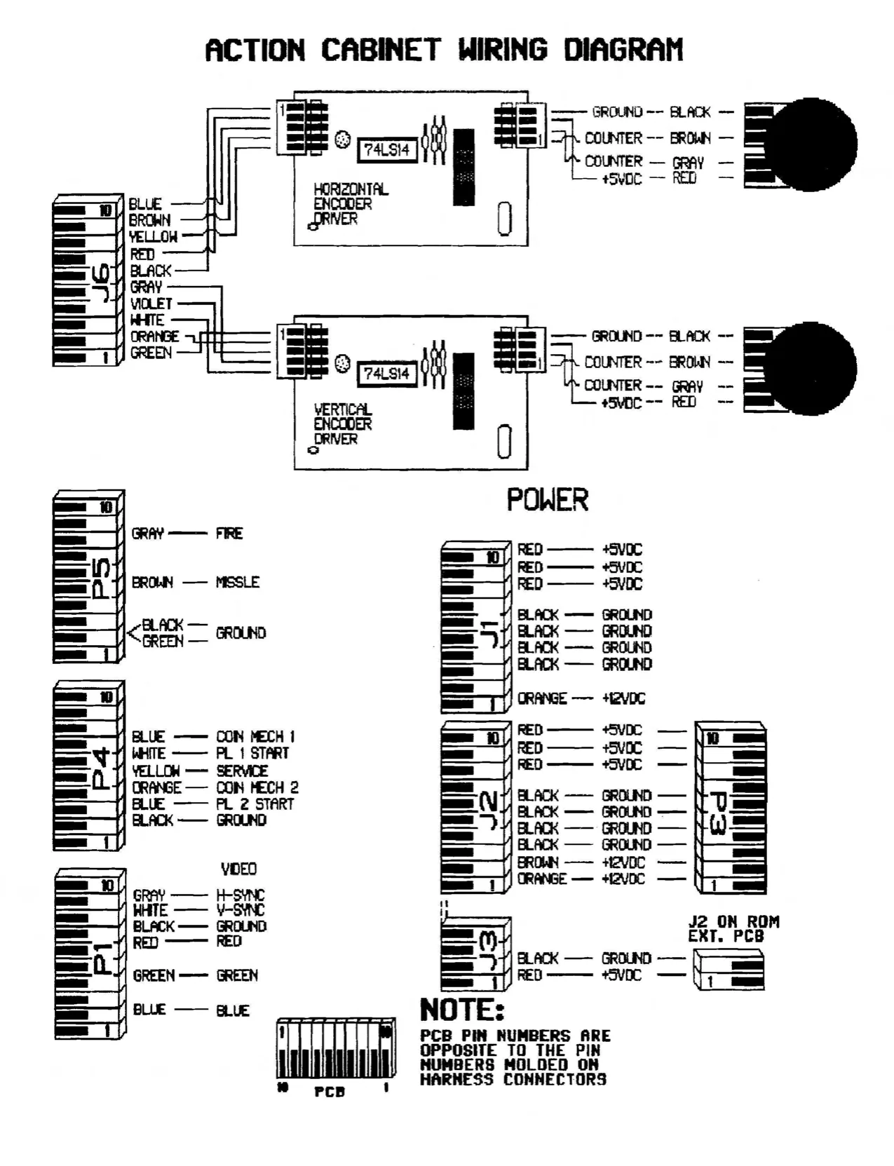
- Action Cabinet Wiring Diagram . Action Cabinet / With Seat . Control Panel and Power Supply Assemblies Vertical Mounting and Motion Assembly Horizontal Mounting and Motion Assembly Switching Power Supply Rom Expansion Board Diagrams Multi-Function Board Diagrams Main Logic Board Diagrams Monitor Schematic [oo momom
FSoSPnogay a PAGE NUMBER
INSIDE FRONT COVER INSIDE FRONT COVER INSIDE FRONT COVER INSIDE FRONT COVER onoeo ONORWNDY
CENTERSPREAD
THE CARE AND FEEDING OF A VIPER
CONGRATULATIONS
With the purchase of a new VIPER game or mod you’ve become amember of TEAM LELAND. This membership enables you to enter a world of dependable products, quick and efficient customer service, and worry-free operation, seldom experienced in this world of “throw away” and “planned obsolescence”.
A little cleaning and a few checks after each collection will keep your new game a steady earner for a long time to come.
FIRST: THE SET-UP
(If you have a mod for Danger Zone, go to the Kit Installation Section) After unboxing the game and before plugging it in, check the cabinet for dings, scratches, or gouges and notify both the delivery agent and your distributor of anything you find that does not meet with your approval.
Unlock the cashbox and check the game for the following items:
- Power Cord
- Back Door Keys
- Action Seat Mounting Screws Got it? Good.
Check inside the back of the game for loose ICs on the board, loose connectors, or anything else that just doesn’t seem right.
NEXT: THE POWER
All set? Well then plug that puppy in (grounded outlet only please!), turn it on (the interlock switch is inside the back door), and check for smoke. When the picture comes up, go to the bookkeeping and diagnostics section of this manual and go through every function. Check for proper settings, clean and adjust the monitor (VERY IMPOR. TANT!), and adjust the sound.
FINALLY: THE PLAY Now PLAY THE GAME!!!! Play it a few times. When you are sure that it works and is set to your satisfaction, it’s time to make some bucks.
EACH COLLECTION: THE UPKEEP Check the Bookkeeping and Game Duration Statistics to see how well your Game Set- Up options are working. Do some tinkering if you don’t like what you see. Make sure the game is clean and working properly. (HINT: Put a couple of coins through each coin mech to check for proper operation and play a game.)
GOOD LUCK - GIVE US A CALL - WE’D LIKE TO HEAR WHAT YOU HAVE TO SAY!!
THE LELAND CORPORATION WARRANTY
The Leland Corporation warrants that whenever the video display (monitor) and/or the power supply and/or the printed circuit boards and/or all parts contained therein are furnished with its product, that such part or parts will be free from defects in materials and workmanship for a period of sixty (60) days from date of shipment. The Leland Corporation’s warranty of above parts is subject to the normal use and service of its product. No other products or parts thereof are warranted. If the products described in this manual fail to conform to this warranty, the Leland Corporation’s sole liability shall be, as mutually agreed, to replace or repair such products which are returned to The Leland Corp. during stated warranty period, provided:
a. The Leland Corp. is notified in writing upon discovery by buyer that said products are defective. b. The defective product or part is returned pre-paid to The Leland Corp. plant with a Leland Corp. Returned Merchandise Authorization (RMA) number clearly visible on the outside of the package. c. An Operator Service Card is on file at The Leland Corp. plant or is included in the package for all returned printed circuit boards. d. The Leland Corporations’ examination of returned products determines to our satisfaction that the alleged defects existed and were not caused by accident, misuse, neglect, alteration, improper repair, installation, or testing.
The Leland Corp. is not responsible for bent pins on ICs not installed by our employees. In no event shail The Leland Corp. be liable for loss of profits, loss of use, incidental or consequential damages.
EXCEPT FOR THIS WARRANTY, THE LELAND CORP. DISCLAIMS ALL OTHER WARRANTIES, EXPRESSED OR IMPLIED, INCLUDING THE IMPLIED WARRANTIES OF MERCHANTABILITY AND FITNESS FOR A PARTICULAR PURPOSE, AND ALL OTHER OBLIGATIONS OR LIABILITIES ON THE LELAND CORPORATION’S BEHALF, AND IT NEITHER ASSUMES NOR AUTHORIZES ANY OTHER PERSON TO ASSUME FOR THE LELAND CORP. ANY OTHER LIABILITIES IN CON- NECTION WITH THE SALE OF PRODUCTS MANUFACTURED BY THE LELAND CORP.
VIPER KIT INSTALLATION PROCEDURE
Calm Yourself. This could be one of the easiest conversions you’ve ever done. Just take this thing one step at a time.
FIRST: Disassembly. Remove the following items from your old Danger Zone cabinet.
- Printed Circuit Assembly
- Complete Coin Door Assembly
- 1 & 2 Player Buttons (NOTE: Loosen but DO NOT REMOVE the two Joystick Assemblies.)
- All Danger Zone Graphics (A little Lacquer Thinner will save a lot of elbow grease.)
SECOND: The Board. (See Action Cabinet PCB Conversion Diagram) Grab the old Printed Circuit Assembly and the new Viper electronic parts and set them on aclean and preferably static-free work area (desk, work bench, etc.).
- Remove the old Danger Zone top board.
- Using a small slot screwdriver or an IC remover, carefully remove the following IC’s from the Main PCB: ul U3 through U9 U67 through U70 U85 U89 through U95 U120
- Insert the following new IC’s into their respective locations in the Main PCB: U3 U67 through U70 U85 (20 pin IC stenciled 0217) U89 through U95 U120 (8 pin IC stenciled 271)
- Insert the audio jumper socket (28 pin socket with wires soldered in positions 5 & 6) into socket at position U87 on the Main PCB.
- Insert ribbon connectors into positions U1 & U99 on the Main PCB.
- Using the supplied hardware, mount the new Multi-Function PCB and ROM Ext. PGB in the positions shown.
VIPER PCB MOUNTING BIAGRAT
- Insert Z890 (removed from U1 on the Main PCB) into the socket at positon U1 on the ROM Ext. PCB.
- Attach audio jumper from Main PCB to the designated connector on the Multi-Function PCB.
- Attach power jumper from the Multi-Function PCB to the ROM Ext. PCB.
- Connect Main PCB power jumper and both ribbon connectors.
THIRD: The Cabinet. (See Action Cabinet / With Seat Illustration) After removing the old graphics, install the new Viper graphics and remount the Coin Door Assy. Install the “Dst Tray” and mount the Action System Seat. HINT: When applying the control panel graphics do not remove the joysticks. Simply pre-cut the joystick holes in the new graphic and cut a line from these holes to the nearest edge of the graphic. Then peel the backing from the top portion of the graphic, align the joystick holes and adhere the graphic. Now peel and stick the rest of the graphic.
STOP HERE --- GO OVER EVERYTHING YOU'VE DONE THUS FAR.
All OK? Fine, you’re almost done. Vacuum all the dust and stuff out of the cabinet. Clean the monitor. Install the new PCB set. Tighten up the control panel. Plug ’er in and power-up.
GOOD PICTURE? If not, adjust it now and as long as you are going to be in diagnostics to adjust the picture, check out the other functions. Do the controls work? Are the Bookkeeping and Game Set-Up sections to your liking?
Last but not least - PLAY THE GAME!
We at The Leland Corp. would like to thank you for your support and would like to hear any questions or comments that you might have. Our goal is to produce the very best amusement products in the world and we invite your input.
LELAND CORP. ACTION SYSTEM PCH CONV! ON DIAGRAN
REMOYE OLD TOP BOARD
C EEEFPEEEET elLelelel=Jel-]*) 3 EXT. BOARD \ SHAFT ENCODER t POWER JUMPER
“A AUDIO OUT
REMOVE ALL ICs FROM SHADED ATTACH SOCKET SOCKETS AND REPLACE WITH W/AUDIO JUMPER HERE AND FEED NEW PROGRAM Ics. THROUGH YOL. CONT. (MAIN PCB) HOLE TO TOP BOARD. rece
REMOVE 280 - INSERT RIBBON CONNECTOR IN MAIN BOARD SOCKET
- INSTALL 280 IN TOP YIDEO
REMOVE NOT USED i
TO: THE TECH
FROM: THE GUY THAT WROTE THIS MANUAL
First of all, that little card that fell out when you opened this manual is your operator service card and we would appreciate it if you would take a couple of minutes to fill it out and send it to us with your comments. It is also a good idea to record the serial number information in the space provided at the front of this manual for future reference.
Next, this manual is not written for the “bench” technician except for the fact that we do include board layouts and schematic diagrams. As you are well aware, most of the problems incurred in the field are not board related. If you have double checked all the wiring, the power supply, the monitor, and where possible, “swapped” boards and have narrowed a problem down to the board, give us acall and our.crack customer service department will get you going.
Because of solid state electronic circuitry, this game should require very little maintenance and only occasional adjustments. The majority of the probiems encountered by field service technicians are of a type easily remedied, provided said technicians have at least a working knowledge of coin-operated amusement devices, the proper tools, and last but not least, a good attitude and a neat appearance.
FIRST: Approach the proprietor or attendant with a friendly greeting - “Good morning! And how are you on this fine and cheery morning?” SECOND: List your credentials and purpose - “I’m from and | understand that one of our/your amusement machines is not functioning properly.” THIRD: Find out as much as possible about the problem before you approach the game - “Il know that you are a busy man (or young lady) but if you would please explain exactly what the machine is doing or not doing that prompted your concern, | would be very grateful.”
REMEMBER, YOU ARE A PROFESSIONAL!
Now that you’ve made a favorable impression and obtained a few facts, we can get down to brass tacks. (Which reminds me, be sure to check for foreign objects on the board.) When examining an ailing machine, you may want to use the following flow chart as a foundation on which to build your troubleshooting approach.
TROUBLESHOOTING FLOW CHART
DON’T TOUCH THAT SWITCH !!!
Before you reach for the power switch take a good look at the game. Open it up and check for loose wires, bad connections, or burned spots. Look for spilled drinks and signs of vandalism. These quick checks will save you a lot of time.
After you've eliminated the obvious, start digging.
POWER UP
NO POWER
CHECK FUSES AND POWER CONNECTS
GOOD PICTURE
GO TO DIAGNOSTICS (SEE DIAG. MANUAL INSIDE FRONT DOOR) CHECK FOR CLOSED SWITCHES ON COIN DOOR AND CONT. PANEL. CHECK FOR LOOSE ICS AND BENT IC PINS
POWER SUPPLY
SEE: A NOTE ABOUT POWER SUPPLIES NO PICTURE
COIN UP START GAME AND LISTEN FOR SOUNDS
CHECK SPEAKER CONNECTIONS & ADJUST YOLUME
TURN UP SCREEN CBRIGHTNESS) ON
MONITOR
Never take anything for granted. This is easy to do if you are in a hurry- You’ll kick yourself every time for missing a broken wire or loose connector after spending hours looking in the wrong place - | have. BRIGHT SCREEN NO VIDEO
CHECK CONNECTOR FROM PCB (P1) TO MONITOR - ESPECIALLY GROUND NO BRIGHTNESS
CHECK MONITOR POWER, FUSES & CONNECTORS. ALSO CHECK TUBE FOR DAMAGE.
THE TROUBLESHOOTIST’S SECTION
A NOTE ABOUT POWER
DC POWER The computer board in this machine operates most efficiently when the power supply is providing a steady +5.1VDC (+0.05VDC). When checking DC power always put your leads across the power inputs on the main board and be sure that the +5 voit supply is between +5.05VDC and +5.15VDC. Also be sure that there is less than .005 volts AC riding on the +5 volt line. If you do find AC on the DC line, suspect the filter capacitor or the rectifier on the power supply. Low voltage or AC on the DC lines is the main cause of the following problems:
*“Garbage” on the screen. *Computer “Freeze”. *Coin or Coin Meter malfunction. *A variety of seemingly unrelated problems.
AC POWER Connect this game only to a grounded three-wire outlet which provides between 108 and 132 volts AC. If you have only a two-wire outlet we recommend that you hire a licensed electrician to install a grounded outlet. The possibility exists that players may receive an electrical shock if this system is not properly grounded.
OUR SERVICE DEPARTMENT
For parts, service, and technical information first contact your authorized Leland Corporation distributor. For additional technical aid feel free to contact The Leland Corp. Customer Service Department at (619) 562-7000 Monday through Friday from 8:00 AM to 5:00 PM Pacific Standard Time. To provide you with the quickest possible response to your questions, please have the following information ready when you call:
- Your game name and serial number.
- Any reference materials and a list of observations.
GENERAL SHOOTING
GARBAGE Check: Power supply voltages. Closed switches on control panel or coin door. Loose connections or loose chips on board. NO SOUND Check: Loose connections. Low +12 volt supply. Bad speaker or pot. (See BUFFERS) NO CONTROL OR FUNCTION SWITCHES (Including coin switches) Check: Loose connections or broken wires. (Be sure to check ground connections and wires.) Closed switch. Input Buffer. (Follow edge connector trace to the first chip on the board.) - (See BUFFERS)
MONITOR SHOOTING
NO PICTURE Check: Power connection. Blown monitor fuse. Video connection. (Check for continuity.) Turn up screen control and check for brightness. Broken tube or neck board. BAD OR NO SYNC Check: Sync and ground connections. Sync polarity. If your monitor will not handle negative sync you may have to install the following inverter circuit. (See BUFFERS)
BUFFERS
An I/O buffer is the component that connects the actual computer to the outside world and, as such, is the part most likely to fail. Check the following list when attempting to isolate possible problems. First and second choices are given. (M = Main Board, I/O = Multi Function Board.)
PROBLEM AREA
COLORS OR SYNG
PLAYER CONTROLS NAD/OR COIN INPUTS (See sheet 4 of main pcb schematic.)
AUDIO (Bad channel- 0 through 5) COMPONENT
1st 7405 (or 74805) 2nd 74LS374
1st 150 ohm resistor pack 2nd 74LS257
1st 7524
2nd 7533 PCB LOCATION
M - U24 M - U37
M - RP3 through RP8& M - U117, U118,& U119
10 -U35(CH5) THROUGH U40 (CHO) VO - U31
ABOUT MECHANICAL COIN COUNTERS
We have not installed a mechanical coin counter on this game for two reasons:
- The bookkeeping program on VIPER™ js very accurate and includes not only number of coins dropped and dollars earned but also the number of tests and coins in a given period. (See BOOKKEEPING in the DIAGNOSTICS MANUAL.)
- These mechanical counters produce an inductive “kick” that will damage components on the circuit board. Checkerboard video is the most common. To see if this is in fact your problem — take a look at the “NMI not” signal on the master Z80 (pin 17). If a low output is observed, try replacing U114 (74LSO8) and/or U119 (74LS157).
HOOK BOTH COIN SWITCHES TO EITHER P4 PIN 5 OR P4 PIN 8.
NORMALLY OPEN COMMON
+5¥DC
BOOKKEEPING AND DIAGNOSTICS
To enter the Bookkeeping and Diagnostics program: *Press and hold the 1 Player Start Button. *Press the Test Button (located inside the front door). *Release both buttons.
MAIN MENU
Upon entering the program a Main Menu will appear. Follow the instructions on this menu to select and enter the desired function. Notice that the program serial number is also displayed in the bottom left corner of this screen.
MAIN MENU
SELECT FUNCTION WITH ONE PLAYER START BUTTON ENTER FUNCTION WITH TWO PLAYER START BUTTON
BOOKKEEPING DIAGNOSTICS
GAME SET-UP
MALL OF FAME GAME DURATION STATISTICS
RESTART GAME CANCEL CHANGES AND RESTART GAME
SN = XXXXXXXX
BOOKKEEPING
The Bookkeeping function is your game accountant. It records the lifetime earnings of your game and allows you, through the use of resettable “PERIOD” totals to keep track of weekly, monthly, or location earnings.
THIS FUNCTION DOES NOT AFFECT THE NUMBER OF COINS PER CREDIT! (See the “GAME SET-UP” section for this information.
BOOKEEPING
SELECT FUNCTION WITH ONE PLAYER START BUTTON ENTER FUNCTION WITH TWO PLAYER START BUTTON LIFETIME PERIOD COINS COINS DOLLARS COINS DROPPED - MECH 1 0 {') -00 * COINS DROPPED - MECH 2
TOTAL COINS DROPPED SERVICE BUTTON PRESSED -
TOTAL CREDITS GIVEN
CIRCLED AREAS MAY BE CHANGED
RETORD TO AAI MEDO
DIAGNOSTICS MENU
Invoking the Diagnostics function will open a very complete and easy-to-use set of tests designed to take the grumbling and hair-pulling out of adjusting, troubleshooting, and servicing your machine.
You will notice that the diagnostics section has a sub-menu of its own, which is intended to help isolate problem areas.
DIAGNOSTICS
SELECT FUNCTION WITH ONE PLAYER START BUTTON ENTER FUNCTION WITH TWO PLAYER START BUTTON
BUTTONS AND CONTROLS TEST
PROCESSOR MEMORY TEST
VIDEO ALIGNMENT TEST
VIDEO MEMORY TEST
AUDIO SUBSYSTEMS TEST
VIEW BACKGROUND SCREENS
BETURD To h~aIn
BUTTONS AND CONTROLS TEST
This test provides a quick examination of the state of all buttons and controls as well as an easy range-setting format for the horizontal and vertical position sensors. There are two types of position sensors. In the first of these devices, horizontal and vertical indexes or flags rotate through optical sensors to locate the directional middle of the horizontal and vertical movement. Suspect improper positioning of these flags or failure of the associated driver board when the horizontal or vertical scrolling indicators are not centered on the test screen. The second device, the encoder shaft, senses the amount of horizontal or vertical movement. These encoder shafts must be manually centered and the optimum readings are shown on the test screen. To set either encoder, loosen the mounting bracket enough to allow the small gear to move freely, adjust to the proper reading, and reposition the encoder assembly. Be sure to allow the small and large gears to interact smoothly with each other. DO NOT force them together too tightly.
PLEASE PRESS THE FOLLOWING BUTTONS PLAYER ONE START CLOSED «— SWITCHS SHOW PLAYER TWO START OPEN “CLOSED” WHER MECH ONE COIN SWITCH OPEN PUSHED. MECH TWO COIN SWITCH OPEN SERVICE SWITCH OPEN
FIRE BUTTON OPEN MISSILE BUTTON OPEN
HORIZONTAL SCROLLING: S12 (*+5 AT REST)
PRESS FIRE AND MISSILE AT THE SAME TIME TO CALIBRATE TURRET. PRESS THE PLAYER TWO OR SERVICE BUTTON TWICE TO EXIT
PROCESSOR MEMORY TEST
The Erasable Programmable Read Only Memory (EPROM) and Random Access Memory (RAM) chips are storage areas for the actual game guidelines and are accessed by the Microprocessor section. The percentage of field failures in these areas is very low but when problems do arise they can be a bear to track down. This next test samples the action of the processor section and notes any incongruities.
PROCESSOR MEMORY TEST
MASTER ROM TESTED EXAMPLE: MASTER ROM GOOD MASTER ROM TESTED BAD
oo CHIP UXX SUSPECT
MASTER RAM TESTED MASTER RAM GOOD
COLOR RAM TESTED COLOR RAM GOOD
SLAVE MEMORY TEST
SLAVE ROM GOOD SLAVE RAM GOOD
PLAYER 2 START EXITS TESTING
VIDEO ALIGNMENT TEST The picture on the screen is the most important and the most neglected part of the game. It is a proven fact that a dirty, misaligned, or unfocused screen will cause a player to walk away even if the game is his or her favorite piece. A little elbow grease and a couple of minutes taken to go through these adjustment screens will make a big difference in the cashbox. Use all three screens to adjust your picture and then go the “Background Screens” section to make sure the game looks rich.
THE CROSS-HATCH SCREEN Used to adjust focus, size, contrast, convergence, and alignment. Notice the x’s in the corners. Wavy horizontal lines (see inset) denote bad contrast. The background should be black and the lines should be white.
RED AND GREEN TEST
RED AND GREEN SCREEN Adjust screen control so that the green color bar shows faintly on the one level and then use the red cutoff control to adjust the red to the same intensity.
BLUE AND MISCELLANEOUS
BLUE AND MISC. SCREEN Use the blue cutoff control to make the gray color bar look gray. Adjust the red and green drive controls slightly if necessary to make the white color bar white.
VIDEO MEMORY TEST
A video memory test is an asset in any troubleshootist’s game plan and “praise be” we’ve included one in our game. This test is invaluable in isolating those “lines on the screen” or “pieces of stuff in the picture” problems.
<& So 2] o ky : > z Qa am aa un o F4
yy % y Z Z Z Z Z Z Z
Z
STAND BY FOR VIDEO TEST
PRESS 2 PLAYER START TO END
SSS SISSON
AUDIO SUBSYSTEMS TEST
The sounds are the second most important feature of any game and are essential to the “feel” of the game. The volume or level of sound is, for the most part, dictated by the owner or attendant of a location and is thus a “given”, but the quality of the sound is a function of the program. This test will help in your quest to find those odd sounds or remedy the lack of certain sounds.
Some Sound Advice: Those annoying ATTRACT MODE SOUNDS are supposed to draw attention
- let them!
AUDIO SUBSYSTEMS TEST PRESS PLAYER 2 START TO END
AUDIO PROMS OK AUDIO RAM OK
COMMUNICATION TEST PASSES
8 BIT DAC TEST <FADING TOWES> CHANNEL 0 C1, 2, 5,4, 5,) 10 BIT DAC TEST DAC INTERACTION TEST <6 TONE PULSES> CANNEL tn rrr C1, 2,5, 4, 5,3 Music TEST <CHARGE TUNE >
BACKGROUND SCREENS
The background screens are shown while the EPROMS, which contain the information for these screens, are displayed at the top of the screen. This test is not only helpful when looking for those “glitches” one sometimes comes across in the background of the picture, but may also be viewed as a visual test of the color and picture clarity after the Video Alignment Test has been completed. And now, back to the Main Menu!
PLAYER UNE ADYANLES PLAYER TWO EXIT TURRET VIEWS SCREEN
GAME SET-UP
The game set-up section is vital to the condition of your cashbox. When used in conjunction with the “Bookkeeping” and “Game Duration” areas of this diagnostics package, this function will keep your game in the thick of it for many collections. The coins-per-credit setting ranges from 1 coin - 1 credit to 20 coins - 20 credits and all denominations in between. We recommend that the attract mode and continue play features remain “ON”. The difficulty levels may be set from 1 (easiest) to 8 (most difficult) and the number of lives may be from 1 to 5 per credit. I’m sure that you will find that it pays to keep on top of the records and do a little tinkering to keep your game fine-tuned for profit.
GAME SET-UP ‘SELECT FUNCTION WITH ONE PLAYER START BUTTON ENTER FUNCTION WITH TWO PLAYER START BUTTON COIN MI
CIRCLED AREAS eaalt AY BE CHANGED
CREDIT EXTRA PLAY ATTRACT MODE SOUND - DIFFICULTY LEVEL ---- NUMBER OF LIVES TO START WITH CONTINUE PLAY FEATURE
RETORD TO CID REO
HALL OF FAME
Every once in a while it’s a good idea to let someone else get to the top. This feature also helps when running tournaments.
HALL OF FANE
‘SELECT FUNCTION WITH OME PLAYER START BUTTON ENTER FUNCTION WITH TWO PLAYER START BUTTON
ERASE HALL OF FATIE OW EXIT
aTORS To FRO SoD
GAME DURATION STATISTICS
This section is your REPORT CARD. It lets you know how well you've done at setting your game for maximum earning power. Since this is a “lives-per-credit” game, your game keeps track of the average length of games played for you. Use this tally along with your “Game Set-Up” function and try to keep each game between 2 and 2-% minutes.
GAME DURATION STATISTICS INCTION WITH PLAYER ONE START BUTTON INCTION WITH PLAYER TWO START BUTTON AMES: 5 ‘TWO PLAYER GAMES: 0 AME TIMES: AGE THE: 2:00 ce
|! : Sgueusnunn $205
AVERAGE TIME: 2:00 ER Oi Gi
oO 2 00 2 30000 oo 0 0 0 90 «0 0 (0 o AME TIMES: 3
0 01 300 2 0 «O oO 20 0 oo 0 700 0 70 00 o Fs z
§ RESET REGULAR GAME STATISTICS RESET EXTENDED BAME STATISTICS TO RAD OID
AC/DC POWER CONNECTION Lot — YS
af GROUND BRAID
NEUTRAL | A yj FT
- GND = +12V
a HOT nunc |
POWER CORD
a
° =
° a
BROWN
BLACK
GND
E.M.I, FILTER
INTERLOCK SWITCH il | CONTROL PANE: | NHnoronwnna a
Horwonan aad
DHorwnt rad
FUSE 5 AMP SLOW BLOW WHITE GREEN A.POWER SUPPLY +5V @ 7A -5V @ 1A +12v @ 1A B, MULTI-FUNCTION BOARD C.MAIN LOGIC BOARD
ISOLATION TRANSFORMER D.cIRCUIT PANEL PLATE
SEC PRI MONITOR PIN 10 PIN 1 OUR PIN-oUT IS OPPOSITE OF THE PIN-ouT PRINTED ON THE CONNECTOR I.E. PIN 1 IS PIN 10 FOR A 10 PIN CONNECTOR
GROUND BRAID
A LELARD CORP. ACTION f 20-30101-01 A CABINET 7 WITH SEAT Door Rear Housing eee eet eres 20-30103-01 21-31005-01 Frame, Rear Door Monitor Plastic
20-30060-01 21-31025-01 Moniter Tep Reteiner 19” Bezel Sve. Switch/ ¥ol Cont. Assy. 21-31009-01 ___2!-32050-02 (See Centro} Fork a 6 *e [pPlex, 1/8" Panel) Plastic x14-7/8" \ 20-18050-01 x21" Clear Brit, “Z> Left
PCB Mtg Plete 20- 18050- 02 Wj] ~_Reteiner Brkt, “Z" Right 71-10900-01 PCH Mts Plate ! 19-30025-01}, ,4" 20-300350-01 20-30010-01 [| Cein Vault
71-010834-01 oe 30063-01 Speaker ,8" yy Round F)
Coin Door Mt. Shelf angle w/o Yault Support Brkt. Metal Shelf Flet 22-10819-04 (Zea) 38-16601-02 Plate (Zea)
7 7 - 5- Assy, Power Supply Decal, Coin acap Oettce 21-31007-01 Door, Viper Fork Plastic Housing (Zea N 22-10819-01 Decel, Side Penel Viper (Zee)
32-31050-01 Action Cabinet 32-31051-01 = 20-12398-01 Seat, Action Sys. Speaker Grill 6x9 (Zea)
22-10816-01 Decal, Seat ——y 22-10815-01 Right, ¥iper 08 UC Decal, Seat Left Viper “(not shown) 22-10814-01 |" Decal, Seet — Back, Viper % 15-20001-01 ‘—_—__———_ Dst Trey, Act Sys. Seat
LELAND CORP. ACTION CABINET CONTROL F PANEL AND POWER SUPPLY ASSEMBLIES
38-30025-01 22-18300-02 37-12545-01
| - | = | - | Assy, Cnt. Pal. |
Lexan, Cat] Pal, Jystick Trigger /Fire ’
| Viper | — But. 1594310 (Zea) | ast tab |
21-10105-01 37-11192-02 21-10106-01 ABS, Right End ABS, Left End Cap, A/S Cat Pol Cep, A/S Cnt Button, Short, Red (Zea) “
20-30070-01 ~ ns we Handle. Sa Mete Z| Tubing, Act Cab S| So 1 7891-01 37-11373-01 7/8"-9 Jam 25-18078-01
| Lock Wesher, | Switch, w/Mntg Brkt (Ze) | Nut (4ea) |
7/8", Split. | 20-30077-01
| Cat. Poi. Metal | 37-11192-02 | ul |
87-12143-
| =o | Housing, Act Cab | Button, Short, | -—25 |
Cord, Power, 18/3, Svt,,7.5 ft. Red 51-12501-01 a} = Potentiometer, 500ehm °
| 32-18100-01 | 20-13136-01 | 37-11373-01 |
| Base, Wood, . | | Brkt, Serv Sw | Svitch, w/Matg Brkt |
63-12131-01 Power Supply (bottom view) Filter, AC Line \ 34-12155-01 Clip, Fuse / 82-12150-01 od Power Supply Hl ‘ 20- 10863-01 Brkt, Interlock Switch IN
43-11704-01 “Fuse er Transformer, _—__ isolation 37-10893-01 Switch, Interlock
r— 20-31045-01 20-30050-01 i¢— Frame, Monitor 20-31043-01 Yert. Bearing & Plexi, Black Flange, Yert. Locking Collar Bearing 39-10819-01 Monitor, 19" Color RGB Horz 20-10526-01
25-18250-01 Vert. Motion Shoulder _! , Braced Cam Bolt 1/2" x 2142 20-31050-01
Tension Cam 20-13710-01 ; Specer, .710 Bearing Seen.) 25-18005-01 Shoulder Bolt 20-30085-01 V-142°x 1/27 Spacer, Yert. Pian 20-30043-01 Monitor Metal Cradle 20-31065-01 Spring, Cam Tension (450- 21-31003-01 —in.Ibs.) Outside Plastic Shaft Cover A LELAND CORP. ACTION CABINET
A VERTICAL MOUNTING AND “ 21-3001-01 : COTO ABE. Inside Plastic . : . Sheft Cover
20-10976-01 Brkt, Driver 26-18012-01
| Brd. Yert. | Geer, 12 Teeth | 80- 18010-01 |
| 20-18113-01 | (42412) EAW | PCB Shaft |
Index, Yert Encoder Driver
Geer Mtd.
25-18003-01 Shoulder Bolt 1/2"x 2-1/4" 50-1157 :
- 5-01 Shaft Encoder 20-31045-01 26-18048-01 Yert. Bearing Geer, Yert. 20-10513-01
| 46 Teeth | Spacer 50 | 20-31043-01 |
(H2448) EAW ("0.0 1/2" 1.0.) Flange, & Locking Collar 20-10975-01 Brkt, Vert. Encoder w/Gear
20-31040-01 Bearing, Horz. & Locking Coller 20-31042-01 Flange, Horz.
26-18072-01 20-10587-01 Gear, Horz . 96 *——— Brkt, Lg. Encoder (Horz Teeth (H2496) EAW 20-10986-01 26-18015-01 Brkt, Z Horz. Driver Brd.
80-18010-01 Gear, 15 Teeth (H2415) EAW 20- 10985-01 1s, Brkt, Horz. Encoder = ea Sheft Encoder Adapter = river 20-18111-01 50-11575-01 Shaft Encoder Index, Gear Mtd. Horz. Encoder (Plastic Flag) ({LELARD CORP. ACTION 20-30035-01 CABINET HORIZONTAL &£ /+_———_ Metal Monitor Fork HOUNTING AND HUTION g W/Sheft ASST. :
20-31050-01 ahah Bearing, Tension Cam bt r . o2/u6 142" x 1-1/2
25-18250-01 Shoulder Bolt 1/2" x 2-1/2" 20-31040-01 " 4 Horiz. Bearing 20-13810-01 | T & Locking Colla Cake wo 20-30020-01 “OD. 72° 1D = - C100. x 172" 1.0) Metal Shelf/
Bese Plate
20- 30025-01 Horz. Tension Cam 20-30022-01 r Horiz. Mete] -_____+ Tension Bar | L
20-31065-01 Spring, Cam Tension (450 in. Ibs.)
SWITCHING POWER SUPPLY
ORIGINAL DESIGNER: _PETER'CHOU
Ze duYvOd NOISNVdx4 WO gq Aau TO-00061-08 # j}u0d # jOoluSs [ seeumvedlle " l ndd 08z [ ore we ill elGZze C elSZ2 2lSZe eisdze Cl eo 2isdze er etG22
us 27512
us zeeBcru 1 ao tetas 11 pe
Sc8s3e35
a y J2
2PINCONN
ci-cia t cii,ciz Ha Tiere bist 10-0ar THE LELAND CORPORATION mee TRaviston @—19800—01| B
This page reads as a drawing: its text was drawn rather than typeset, and comes out in fragments. See the original scan.
K7000 COLOR MONITOR SCHEMATIC DIAGRAM
| +20
I I >
VIDEO
Fa | Gare 2|RED af RN nfeLu -}6No T 6 P7 AA
TOK 2N3904 a7 82k RT
clo fo ao
lev
| Pr | RB | 2Nn3904 | 26 | |||
| L | Sex | a | cos Ree | TTT | BRIGHTNESS | tiv. |
| reli | 2N3904 | 10 | Tot | J |
GRN 24 =
| au [34 | Na ) | 1k | BOW N oo“ | ||||
| cis | = | FAC TORY. | ADJUST. | ||||
| + VERT SYNC | R46 | 7 | n | sv | R36; | 220) | |
| anon sync [6&1 | oT | pee nas | P53 882 | TEES oe Be | " | |||
| ie | an | rey | |||||
| id | P| | os | gf | et | PE | Te HO | CN |
: +) CONTRAST
| ter | 1, Sov OF | R26 | R27 | R35 |
| UPCI397C | ‘8.2K | cal | k |
eet ceees
| T | \ | cs |
Te]
| eels | Q)| | gee” |
CUTOFF DRIVE CUTOFF DRIVE CUTOFF DRT —= ALTERNATE CRT AND NECK BOARD
SCREEN ono Rs9 12
| = vert sync |2€+ | i“) | R50 | rons, 3k | |
| = nor sync (se! | Ns | 10K | cis | ‘Rez | |
| 1 | —}o2 | 2ns004 | 1 50vr | BK |
| R47 | +| | f | ||
| Pa | Raz | 100 | resp | GHOLD, |
- ‘2N3904
| Rss | cis | R51 a7, |
bcd ok | (>
R301 RIO! i2ovac 220,15W 6.8K *50/60H2
| ae | |, | Ll) | |||
| A | 2s TI /eo | nes,| | 30 | ||
| Fi | sz $F | IOP 3 O | 100 Reo) | 20x] | 2K | UPCi378, |
TPa tk
| ceo | IK | 220K | " | ues | * |
+| C23 24 RO JHORIZONTAL POSITION Te HOR aio [asczfaez 5% Lee
HORIZONTAL OUTPUT
tev
cao
1 33K L,
fe DEGAUSSING COIL
RIES MONITORS. \ 2 SS Se protean ‘R302 IS PRESENT ONLY ON I9K7600 AND 19K7900 SE- VERTICAL VERTICAL POSITION
vro Bur S0-60Hz
R78 1K ALTERNATE CIRCUIT FOR io? LATER PRODUCTION
vRa
VERTICAL SIZE : REO 2.2K.
ul Size ADJUST. R93
C44 1, 100v
R98 R99 2.2K,1W
L2 LINEARITY
DEFLECTION YOKE NoTes
| ALL RESISTORS ARE IN OHMS,174W,5% UN- LESS OTHERWISE INDICATED.
2 CAPACITANCE VALUES LESS THAN | ARE IN MICROFARANS. ABOVE I IN PLCOFARADS UN SS OTHERWISE INDICATED.
| 3 CIRCLED NUMBERS INDICATE LOCATIONS OF CERTAIN WAVEFORM READINGS.
QS CAUTION sarety cRITICAL COMPONENT.
We cay eaoiation revareo component
REPLACE ONLY WITH SAME TYPE PARTS AS SHOWNIN PARTS LIST.
9K7700 SERIES 13K7800 SERIES I9K7600 SERIES I9K7900 SERIES
aa]
ral : as u S$ a ee
2AB-ZAIS 2Da-ZD7 g| a erforfe-fol ealen) lool if Es i aI
a sr] fon {t eu ee PRIS, eecst e082 7? BIL paTTery Lo RES
Tansee tier L 8 4 vs2 } [ = mae] ADB-AD1S
THE LELAND CORPORATION
NEH GENERATIGN SOUND BOARD a
TITLE 288 RAM (BATTERY B/U) AND PROM STSE [ee WUREER FED B |& S97 81-18800-81 a TATE 2-11-87 [SWEET i eF Te
74LS 491 Zn
HeT245 FOR
2 =i a RGS-32 = = a Pe = ws re wi "J FORURT:
le le is DB-ZD7
ie In __ TALS 4g afer OB oF ot 2 es 0?
All IC power
grounds ere
- URT
=~] a-urT TL EAURT, J | iix-UET v
ri eases] fos
+5 | oh
R 4.7K HoT 24a
THE LELAND CORPORATION
NEW GENERATION SOUND BOARD
TITLE ABSOLUTE POSITION
fs a} ] SHAFT ENCODER INTERFACE STSE [CODE [NUMBER FEW [ } B jE8°7 91-18000-01 a
ls
lo tl -fesfoo
- DATE #-11-¢7 [SHEET 2 OF 10 5 2 | :
+
©
D 190K RP2 1.2K
RARE B
RP2 aledeale
sn OP? ae RP2 foo) l= La GS-20 ZDB-ZD7
afeafon
RP2 us. BGS-21 is. 1g 2b?
ue
Is THE LELAND CORPORATION
re NEH GENERATION SOUND BOARD
TITLE OPE. TRACK BALL INPUTS STEE [CODE | NUTEER FEU ZAG-ZA1S 2et Be a rE? 81-18080-01 Tate @-i1-87 TEREET = oF Te . | 3 3 f i
arae_—_ annR——— 2Da-zD7 2AB-ZA1S
@.o1uF uEa 7ALS173, —
OPE c +
4051 eros op 1ns2at Tr 3
11044 iNsza1 a
a 210/18 5 Fe ANeLOG
le B 310 © ]tna si0 F[elofey Vee 610 iE INPUTS want y4 ee) S_] a-IN-@ a] A-IN-1
Uss 710 cone ral |e
0S ol
of |e} og 0
Zu? ps | “ 1NE231
NOTE:
@11 IC power srounds
are IGND
THE LELAND CORPORATION
NEM GENERATION SOUND BOARD
TITLE A/D AND SERIAL TAG INTERFACE SISE [CODE | NUNEER FEU B IE ser 81--18888-81 a
aor PATE @-11-#7 SHEET 4 oF i 2 T 1 ~
i AL-AI6 sol an] ofr Poa tate
canst INTI TEST eCONRD ARDY
(is aan THAT
og es ko po fh io le 88186 ines THTaS Suinre: Tatar aravsel A1a7ss a177s4| ale /s2l als ania ania aniz @Di1 ans AD2 ADt Ave FRE 737. LEZOSS WE 2@s1 FES OSHD i
use
= Te 1-A16
We2 Wed
Ai afonl on} fu TEES cee e |EMSEL Zz ere 2 /CLRINT | 3S
¢INTRD——— ADB-AD1S CINEMATRONICS INC.
TITLE
PROGRAMABLE SOUND BOARD
| 88186 CPU CODE EER 81-18008-81 [EREET = I 1
2 6 s 4 | )
fe +
MEMSEL. 11 ene, 12 Ans, ba num tTu eee
Sear Af al efile lst feaffafeatsafeaealea cafe estes
ADe-AD1S. EPROM at
Ba ball ANG aDz
eof ane ADS
hale ALS Ane cs}ofta|ole-fon}ol SRE Perrerrrs saae6 TAN?
a folels ey i zare , la4i2 13) 26 81 Gyre ai alee Pa?
2 : als Pi
ede u62
THE LELAND CORPORATION
NEH GENERATION SOUND BOARD
FITLe
Hl 88186 RAM AND PROM MEMORY
[SVEE CORE | wunrEer a B |£-¢?| g1-18980-61 B
aren PATE €-31-87 =e LEHEET @ OF 18 fl
a
w
w
ra effin on spoosg}i2 6p 6a efo}o
Pa £
a G ep 30 [48
te uz 24k Rat HoTs74 12K Rao
1D 10 2b 28 an 2a ap 4a sp 5a Paa y Rae Ras. Rad R43 R42
HeTaT4 ip oie iD 2a 2D 30 4D 4a en eo ep sa 7D Pa en 30
Te ea cae balk nafuafio
uss
THE LELAND CORPORATION
NEW GENERATION SOUND BOARD a ENVELOPES
TITLE
HUMBER FEU 81-18908-01 a
STce B : TATE” S-10- 87 TEHEET 75 Te T > rs 7 = T = = es T 7
pac. PURE. afiefolerfes] |
A1-A16 “4 AD@-ADIS HoTs74 enrs24
apo 13[ip 10 12 pe upp 4 3 3
ee ee 4 SE bs our 2 to She a 34
i Cor 18Luk as
2c PGND = uss
HoTS74 43fin 1p 22 An?S24 ne = upp tA.
teens
abi 14] 55 2a LE 30 DE nz rer PS Oh nz vReF PE
zp 20 35 sp 2a [AS
a2 17] Sp ADs 12] 4 ao [8 Ina -
apa 3 len OUT 4
ap 4g [48 sD sa 6p 60 ns Ins outs [2
5D Jos curt ne out2/e
8D i S ln2 207 Ing rer PE
ee 20 2 = aq [34
* aps? | 7p HoTs74 ADTS24 bo uno ia
apa 12 [yp Abi 14] oy 10 12 zo 5. In2 uReF BS ouT @ out2 2 20 tna rer PS
7a [ES & a4 HeTar4 aLrs24 unis -
2a an urerS
eyo}, Al ea}uafaol on Slur usa eyes emits f cre eI vee
HoTS74 apa 13 [Gy 10 12 ADI t4]on 2a DS. ab2 i?|en 50 [2 fos vpn} nz UReF AS our 4
Ane 17] 5p ADS 12] 4p 30 [Le ao LS Da
ADS 3 ep so Ing REF AE Ins ours ft ADs 32] 4n 40 [23 AD sD 5 AUS 6p 60 res 6 rer
Ins ouT1 Slesled
ADS ep Ine ouT2 2
aD? ap z 7a [& 20 In?
Ey Ane? |op a i?HR cs ls) of TF] lonfoole-fuofuntst] Lf PGND us? REF 2. Ine OUT2 In? A ia Zofia REF
S a
Aue eb 89 3 z 4 5 ADE? |p 3a [ = 3
THE LELAND CORPORATION
NEH GENERATION SOUND BOARD a
TITLE
REF 8-BIT DAC’S, BUFFERS
as Us6
ere at SIGE [CODE [HUNEER FEU B | ss7| 91-18000-01 [A [SHEETS oF ie]
rl
Pate 8-11-87 3 Py 3 2 T
al
o
ra ADB-ADIS A1-A16 eecTC S
3] Eas cat ¢ODACHR HoT374 ALD 3s Tin ADL 2D pu? ? len 5a Ava 3] ap exfuo}iofor Ts]
ab413]ep ans f4]ep ADs 17] sy 79 DS
AD? 18] 4p $9 DS
1 doe 1 ws SAIS felon |e fuol
ey a Rak ake # connec ats
*SEE NOTE BELOW CNN fe a iour r *SEE NOTE BELOW
NNN uF s -|ou}on]er|un|uole-
ae ra
ee
uz wa
NOTE
peti? ALL
det i 10uF. APE BYPASS CAPS aN 1uF CAPS
THE LELAND CORPORATION
NEW GENERATION SOUND BOARD
TITLE
cTc’s,
COMMON DAC, AND POWER
STZe cone B |e eer WOMBER FEU 1-18088-81 a
DATE e- 14-87 [SETS OF 18 2 T i
om
+
w
« BO1UF
- 1a Eine Tea ca2 eps nS, i
RP1G
2K 20K our a — 3 r RFIO a ey bns2s pr ui3 OO1UF RPS FPS LFPS 4 sah PS 5 4 20K 12 Fria, 2 + tit 4 gs FRO, a 3 _4,-“insia 180K FE ee1ur RRS RPS R12 R13
our +
i B1UF _ wok 5 FF R4 FB kes age ce NOT INSTALLED
ee - 4 T
c4 wy a4 THE LELAND CORPORATION
MULTI-FUNCTION SOUND BOARD
. TITLE | AUDIO PROCESSING AND QUTPUT STSE [COPE [WUMFER FED B |&sc| 81-18080-01 a | TATE F-i1-87 [SHEET ie ar te]
= = S 4 2 2 1 1
ce zzoour +
7 — Pi- PING KEY PINSOMIT nev D
noe [Jem A BOING KEY eNO
BEGeenesae Ci Bape C9- on ar ne L109 66/4016 i} L vs ca Bi
Ga GO pF Ca = teone SS-ioonr 6 Not ase!
Cis Oar a3er
wf} U J ral cay ses oF Cee thal) cer ra Zio) PRATT PATAYY eve 2nsso4 EAT IN@I@B OF INGIG, as2, ASY SO
Talsite] Pass] Ube yess ef] Dd ery CSTE NETIC) ease) Pass Cae waige on gia.
rg crs S) Taisave} Giases) pases] pfasns] [ere] yiiese) Fig | Ser dee” Grace ere woffa | = ow ete cee Ce! ON eg Te Soe Pan ery
Ua SEP ESCPET gy ORO OERET aco 5 s oe SS cis ie ves “ se eee Suowinty mee) SEE] oo) | ae ee | 7 4 fyeace eg Testeem WHE) _ ae ; 7 CLE) ect £00 Lk Curacten C2 TH C8S)
eBopF car = = PSO zeo-8 #2 =330- f sccneT S7asoa | pores | a3 OME Bon ne ors XI | Hae, 1 tSe eke Ee Mky BE ew em ae E.s\mie ce fils sure en Race Toe cut ort: ae as ‘ aun) ROTH ENTE SUND SP LA
if
‘i 2, SiR BS Wear GV ECT OUITE MD. CHP C226) Ew, Stl,
I RESITUN VRLUEL Ere CHS PESISTORS. NOTES IUNLESS CTHERWISE SPECIFIED O ces. 10/26/87
\car THE LELAND CORP.
CINEMAT MAIN LOGIC
#1 1oane -Ce
12 .cooumite rota | =330— RSS. ye ate jbo wor Seate One|
NOTES UNLESS OTHERWISE SPECIFIED - 7 ry 4 7 3
8 7 6 5
a pene 0183
REA sea 204 lef e Let BSG7F “Ur10 ui1e
ols. ath p—Penear e027 INTACK —— eres C2 wne2 02,3. Peril £2. tee nen t2.3.12) ree 2.5.9, 163 PIED C33 LELAND CORPORATION
PNR £2.83 CINEMAT SYSTEM TITLE 7 | MASTER CPU |
Slade [one | WunEEF B 81-12176-12 DATE 3-25-85 TT EREET y — > a rn
This page reads as a drawing: its text was drawn rather than typeset, and comes out in fragments. See the original scan.
dl z = ® s Ll 3 5 ° ae EET EST Sa-S2-6 aie — { | LO) ct bs a tet} mie Eas ~ Nj 3703] BZIS | so) ch) ' eau £6] SAHOLYT BLYd OFdIN YALSOH rte
ait ooo tt 3 — — eau ct}
HALSAS LUWANID equ crt NOLLvaxod40o GHYTET
- = sam
zn T | i tha Tanne ca [EE =
- aa SS Ol SN 4 = at 3
} et Ss | C8) TLW/m¢- ST 3 — i i er = | z C | T j if [~ ta-89a
ran | pre 1 ! t | | Gi 7 | | bs: mal |
Cs + ——— i _| + . +
+ ast | Et 4 eet
€ cava oaCIA TST J | 4 —— rasqge 06) GNOaXOd OL) , aoplt t = sau? 061
CLNSHAOUTE NagxOS GNOAa) t Crtd + tera et + cer lst
Fad cr ar Crd INOIW ae 3
ej = T shu cra SLYOd LNdino = 34 = SLYOd LNGHT raed ter) 3] = Ce Elz tra a tes g
a] +
w
ra
fs
5 : 7 6 i 5 | 4 3 a Boo —eesiut cea|® we SHNT CE ee SREZET SS y
Jofioley C38 Ss ca7 Fees ! c1ae s cia1 freer —
@iuF oP .e1uF
© a ied wa]
f wif wt
+
{
T elo i
ae ae i
[ik cia? g1uF
L ¢ MDATAL 1}:
ay naz mp1 C2) /61N2,
COIN L nna LELAND CORPORATION CINEMAT SYSTEM a
cae ik cee rer jt e82 rer Bier TITLE GAME INPUT/OUTPUT
ra
re
L_ STze TEER FEW B 81-12178-12 a PATE 4-7-6 [SHEET 4 OF 18
This page reads as a drawing: its text was drawn rather than typeset, and comes out in fragments. See the original scan.
This page reads as a drawing: its text was drawn rather than typeset, and comes out in fragments. See the original scan.
b “
rs
tei
- #3 te] ce) tsa tea unis. pes
uate Uae. UTS DLS een res
a1 eeuDi pe UELS
vas vas. any
uAR pes
—) ce2 UL INE s3 tsa ts) (s3 (83 fa ts] te] ts] sa sa ea wl ca sa sz tsa s3 c1z.172 12.173 £12.17] r12-173
ees weN2
“sD pl] [8] -s10REa rsa COLOR RAM & DAC STRIP DATA NO URITE IF DATA = & aa al at at Ree i 12-173 c1z.173 12.173 12.179 12-173 ci2.172
oo
sr funfuafe-|oofor] == Is]—|e
RES-94 eeu 039)
13, 14 pene 68]
LS374 ie pL
e o 2] en [=
13 ime
18, fe \o] 3p (Le
a sa 3D
1e a 6a en ia
is oan aq ap L& sp [te
14 ee STLO9] — es
a
cy cafe fao] nf]
fos on|et fun} a-[cofan] az
wiz bev surL ce]
en? ene 0)
sa ena 8n2 | LELAND CORPORATION CINEMAT SYSTEM
TITLE SLAVE VIDEO DATA LATCHES
sbi onfor|sele-|e-}¢ [ooo
leg
- /SPCSEL oefeefua|| of =fonf 3] 4] STee [Cone B 81-12178-12 [SHEET FF
w TEER T FEU
T “
16] (103 cio] 19] 1a] tac vFL 173 +s
RGS-07
092 BCLK t2 cs2 Og mod s02 3 19 7} vat Yo! _weysyne 12]
gy
oo] hn}
rac 5 ~ aot be Ss] vai >: sez aS 1 u41 13. $< res vnc
o-|n|o0] i 1 Mae t1za
13] C13] (93 /DELK. t93 a RGS-08 if Bxa——____2.] BRI 3 19 Bx2 4 18
raic. Ls74
a i 15,
a
=|) oft nfiol =f =f onfon L 42
tsk. t[-lesfoo
07-10-14] [7-10.14] £7,10-14) 07.10-147 C1.7,19.149 07.18/14] (718-142 c7.18-142 *bkgnd pixel cnt rgs 7,8 = RAM addr cntrs /UBLANK ee CHPELK C12) ray = a |S peer cia2
+6. t | ee SRL 013,16) LELAND CORPORATION CINEMAT SYSTEM
TITLE VIDEO TIMING
STSE B CODE [NUMBER 61-12178-12 FEU €
DATE Baze= 55 [SHEET 7)
4 T Fy
This page reads as a drawing: its text was drawn rather than typeset, and comes out in fragments. See the original scan.
ue
C13 MDATi C9) enPoSEL— 12 enPeLK PALsaet le} elolole fale]
T enPLDH. —+—+ PALe4B1
t12 emprpp—______} (93 /MPREEL (91 -P1 ts] 7B tea tel ce) ted cea cea tea talc. ala vet vas Yaz oon
vas fein] oo) =
uaa vara_—__18 | ls] fu £51 SDATS 1S) /SPCLK. PALS4e1
(2 /SPLDH. sre 22 RAS vapp [ae] B
ee RAD £9117
lode]
Shi Ral
Sh2 26 RAZ
SIS 3 Fas
Sb4 Rad
S1s 17, EAS
SIs 16, FAS
SD? RA?
a 1)
i cs) veprpn________} 2 Cal /oPREEL u22
LELAND CORPORATION
CINEMAT SYSTEM 5
TiTLe
UIDEO MEMORY ADDRESS MUX
Sse [CODE TWUNEER FEU B 81-12178-12 a sneer ie oF Z T 7
® w «
§3 m a wl so ups q E15
be Ig Ke tr lw ups
uD2 uni Uns upi
bo calesfonfu one una eeuteansal Bw sarerraa weofe-lea Unit
RAP RAS RAS RAS RAS 15 ua
(91 cast Bw Ub2 RAZ = ung
BY UDI RAL 1? unig
b2 Une Zuni,
can ecasHi Zhe. 32 | 692 ROE LLL ©1983 vapD re) z q rd
us2 HH
a RPL ¢92 una Sn, 14 = ia 3 tend rears f ups 1S uD12,
pi Uns. 2 unis)
UBS. i? vpi4
hwutonaal ba whoo|rfas vb? 2 Unie!
FAT RAS RAS Rad FAS vp RA? RAS RAS Raa RAS ne [4S vs,
UDATA
17a
LELAND CORPORATION
CINEMAT SYSTEM
VIDEO MEMORY
Faz Uns. Raz Di 3 vba
Ral UbS. RAL pa az vn}
Fag Ub? RAG pa [2 vps CODE [NUNEER 81-12178-12 3-25-85 [SHEET
c 2 T °
c162 4 163 C162 16) rie) tie) +4
i
i} who} fo eoe|e-feole [lm |o feole-[a foal
cof eho
T casa P20 ole + CHRELK + tei
jas 1708 +
+ 4+ whole-|}
+ u Ea oles] aif
+ © = ae
una pt up2 one ce2 HSvHe He ts] USyNe
toi CLR cia mp3 uPst ria mp2
- ueoL = cia
nas, Ls244
naz zat zaz
naa aaa ae
naa 2A3 la 2v4
naa naa tat ivi 1a2 1v2
nas 1a3 1V3 ale-wloo}o}iol les iad ival /LOLSeL——*4 sey 1a ca aa ise) r1a wall ca}ca}anfoo]e-lua} | PL
LELAND CORPORATION
CINEMAT SYSTEM
FTTLE
COLOR RAM 7“ VIDEO OUTPUT
CORE | WIREER
1] COLUR B
- col ———! =
> 2 ; ;
| 81-12178-12
“Heda? C87 1 i z € r 3 3 é _. gt a0 et a3HsT Se-S7-6 Siva ¥ 2T-82TZt-T8 a SSIACY TYLNOZIAOH ANNOASAOVE
wu WALSAS LUWANID NOILYXOda09 CNY TIT
3] oxawt T cel tase z tel 2xa—t ST
= zy ihe — ZOHS ww l St eonicg — SUH a g———S 1] Soneag dong 3 4 et ees TaPSTRE —F z 3 a —
al
+
ry
»
ri
te > EPB PR EKAIS C15)
1s] 19283 E404 2]a4 suna r+ fe cag ciel sung cas C16]
sun2 2 Sunt 2 we puar C163
fhe
rsa sEKWH Pe puae (152 AB L182 = te1 vaiz——$4} ons 018) #Euaz (15)
1 ce) vale ce) vari—— C82 Yara———s ft
os +5 —Pepyaz 016) Peper C162 b~
puae C16)
rs) uaa ced vas tai var?——j
LELAND CORPORATION
CINEMAT SYSTEM a
TITLE | BACKGROUND VERTICAL ADDRESS STae [Cone | NUMBER FEU B 81-12178-12 a DATE S=7578E [SHEET 1a oF Ie 3 7 3 F = z 7 | ,
- FKALS —
- /BBE——] cag CAL Caz CAs, Cat cas. CAS. CaP
EHeg 18 FHS HAZ 8 In> EHag 7 lag BHA 6 aia co} ala
o]e-fuo}unl foo} cafeafeafea eal sien lefedtes
EHS —& petite i
i i faa} uso} e-}
ea Ea " loo whole rile bsfesfe-
Iz a ure aa
ce
ce
ra) wear 142 BRaDIr ciaa cEBr C147 14a CER VBR
- vERa—> cag EHAG
cal
EHAL
cas HAD
= faa EHAS
cad EMA. reine lsfolu}o
CAS HAS flea} onl fo] fea i RF
CAS EHAE ‘ta)a)/a|a:
is ca? EMA? sladesleol thahele riba a Bad bite af i honfon SAIS /2/5)215)
Ehor}oo|e~}uofunf foo) i
Eva @ Ba eller
z ran
= sf
eal eaealealeafesp sale esjeadenyes
ape) tt cL
use
co w
w
| (143 RES:
LELAND CORPORATION
(141 VBE (143 VBE?
CINEMAT SYSTEM
|FiTLe
BACKGROUND PROMS:
STze WUHEER B 81-12178-12
TATE [SHEET
Jo
oa ESi73 e123 po tt | cae? 4 ge LEA ‘a
al
LAS tho fa
ray ueoL—t-y4 gaa enenk_ff] 4 ~ teonwuer
Lo] Jenlai hol aiNleviea}esteal
cia c14a tiga C183 C353 C183 1s) ris3 ie] cis] e143 e143 TROAWHOTOO
£9] TeLk ce) /$RL +
LELAND CORPORATION
CINEMAT SYSTEM
TITLE
BACKGROUND CHARACTER GENERATOR
STee [Cone | NUMEER FEU 81-12178-12 a
B DATE ~§-75-28 [SHEET Te oF Te 2 | 7
= R43 443 if = 412 188k
BEG O —pepacouT (197
LS374, iD 10 2p 20 2b an jan 40 5D sa eb 50 7D 2a ap 30
tf R2 Res. 82% 3. ra aa 9 180 24K A c3 AE 100pF
ooft|e-fool =] 415) foo] e]e-]
HO Ho MO uss +25u [ie 4
ret [3 hecie = lt cas tur
Lsig2 BR
8 “POR C1182 LELAND CORPORATION 1uF Ler CINEMAT SYSTEM
cr
1N4149, 4 2N3904" TITLE
DAC SOUND OUTPUT
a
RESET q Sut
lus ay a Tobe | RUMEER 81-12178-12
a FEU a
DATE _§-25-e5 [EHEET, TL oF Te
a
+
w
i
| 4 o
naz 32 tae
npe. nas. Esme
D nbs mns 32 yaa 34 |Inaa
nbz mpi 22 Ineo 38 Ipar
a} tsa 7B. 27 hae 2 enrRr Steci BC? vee Ze 24/a9 Fenn
cava ePor—| tea vigiT 32 vost. 32 voor. =p CLK 22 RES. uss roae | 21 1 1 1 RPS
- 7KS 4. 7KS 4.7K 2 3 4 + e/LDCL (173
TOAL 1oaz [13 ee HDCL C173
1oa3 [18 roaa[t? + FEO C12 i eeEPB C14) CFB C16)
toas 1s TORE 10a? IOE6 TOBt 1OB2 IOBS 1OR4 TOES TOEG 1087 ac-a ac-B ac-c Y uy a a) eres" Jie
baz Das aS Das ~fealoo] fu Per tata Iba 2 thao 27 pat 22 thao ue? ones __| J oar PS BANKING
CONTROL
voLUne
oaz one oad one 1z ra 18) = gas; Ss LZ. roa? L 2 ac-apt acete—t ac-cL 17a .sPEakeR Cc i) sPeaKer
k cia four if bones Rag SsKe 24K le 2 R44 24K pacouT—_4 rsa 160K
L322
C13 MeLK 2s 1_luizeap3 ee ee 3 1 2 je -inezs
use Raa R47 | 22EF eck
7 2 a1 180K 162K
NOT INSTALLED
LELAND CORPORATION
CINEMAT SYSTEM
TITLE
GI SOUND OUTPUT
SIZE [CODE | NUNEER B 81-12178-12 Date $-26-e5 [EHEET is
® 2 T 1
This page is a drawing, shown as the original scan.
1841 Friendship Dr., El Cajon, CA 92020-9981 619-562-7000 Telex - 4974293 Cintron Fax - 619-562-9468
LELAND PAR; # 72-11700-01
‘THE LELAND CORP. © 1988 ALL RIGHTS RESERVED