Soccer DP-144-1st-02A
Atari Soccer (Atari, 1980) · Drawing Package · 1 pages · original scan
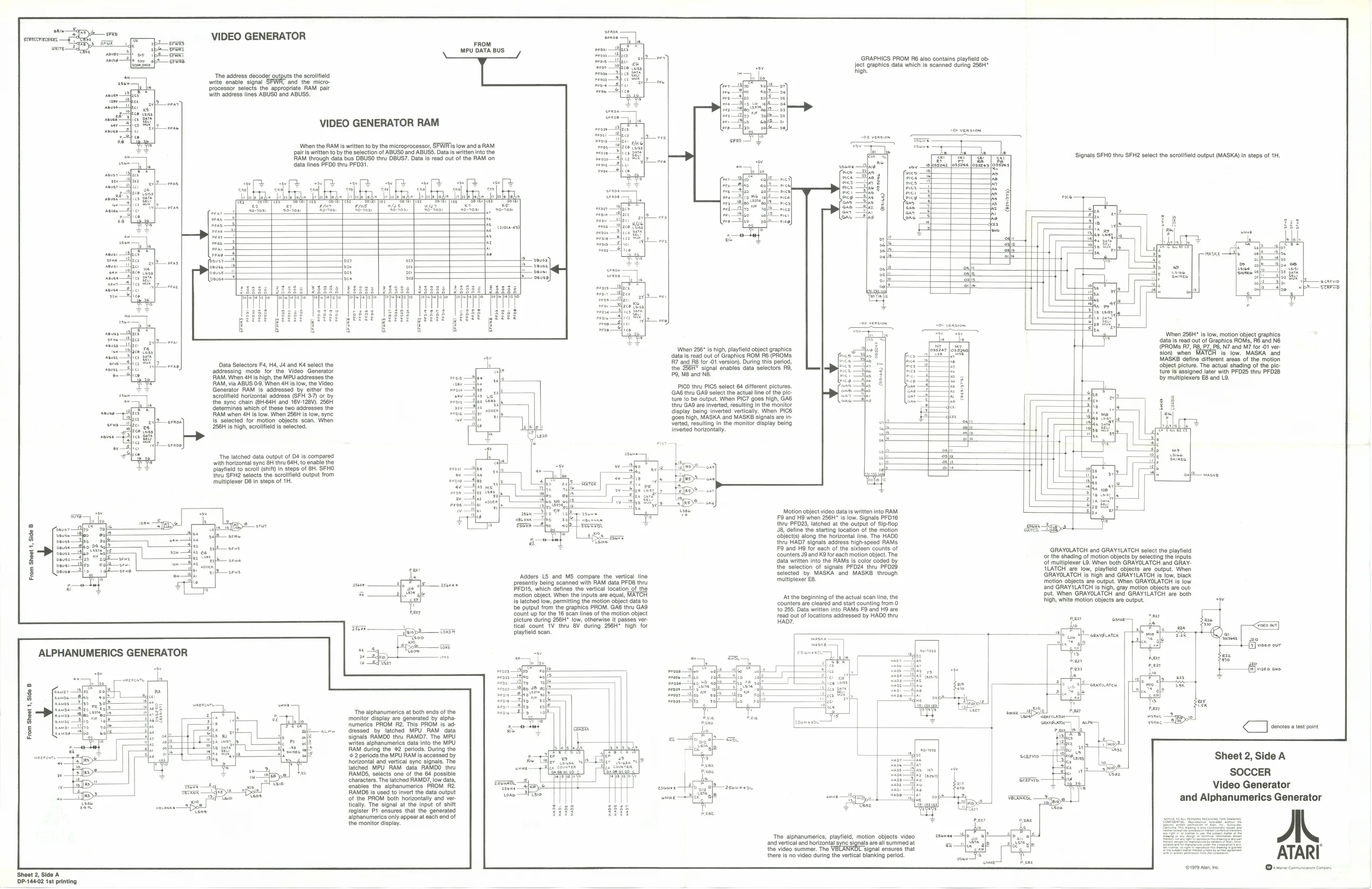
VIDEO GENERATOR
FROM MPU DATA BUS
‘The address decoder outputs the scrolifeld write enable signal and the microprocessor selects the appropriate RAM pair ‘with address lines ABUSO and ABUSS.
VIDEO GENERATOR RAM
When the RAM is writen to by the microprocessor, SFWis low and a RAM
pairs written to by the selection of ABUSO and ABUSS. Data is written into the
RAM through data bus DBUSO thru DBUS7. Data is read out of the RAM on data lines PFDO thru PFO31.
[ohuleTals
co
Data Selectors F4, H4, J4 and Ké select the ‘addressing mode for the Video Generator
RAM. When 4H is high, the MPU addresses the
AM, via ABUS 09. When 4H Is iow, the Video
Generator RAM Is addressed by ‘ether the ‘scrolifield horizontal address (SFH 3-7) or by the sync chain @H-64H and 16V-128V). 256H determines which of these two addresses the RAM when 4H Is low. When 256H Is low, sync Is selected for motion objects scan. When 256H is high, scrolfield is selected.
‘The latched data output of Dé is compared with horizontal sync 8H thru 64H, to enable the Playfield to scrol (shift) In steps of BH. SFHO thru SFH2 selects the scrolfield output from ‘multiplexer 08 in steps of 1H. GRAPHICS PROM R6 also contains playfield ob- Ject graphics data which is scanned during 256H"
sake on high.
= 02 version.
Signals SFHO thru SFH2 select the scroliield output (MASKA) in steps of 1H.
MASK
”
‘When 256" is high, playfield object graphics {data is read out of Graphics ROM R6 (PROMS 7 and 8 for -01 version). During this period, the 256H™ signal enables data solectors R9, 9, MB and NB.
PICO thru PICS select 64 different pictures. GA6 thru GA@ select the actual line of the pic: ture to be output. When PICT goes high, GAB thru GA9 are inverted, resulting in the monitor display being inverted vertically, When PIC6 ‘908s high, MASKA and MASKB signals are in When 256H* is iow, motion object graphics, data Is read out of Graphics ROMS, RB and N6 (PROMs 7, RB, P7, P8, N7 and M7 for 01 ver. sion) when is low. MASKA and MASKB define different areas of the motion object picture. The actual shading of the ploture is assigned later with PFD2S thru PFD28 by multiplexers E8 and L9.
ef 3B
Yerted, resulting in the monitor display being Inverted horizontally.
Motion object video data is written into RAM. F9 and H9 when 256H" Is low. Signals PFD16 thru PFD23, latched at the output of flip-flop 48, define the starting location of the motion ‘bject(s) along the horizontal line. The HADO thru HAD7 signals address high-speed RAMs F9 and H9 for each of the sixteen counts of ‘counters J9 and K® for each motion object. The data writen into the RAMS Is color coded by the selection of signals PFD24 thru PFO2) selected by MASKA and MASKB through GRAYOLATCH and GRAYILATCH select the playfield or the shading of motion objects by selecting the Inputs ‘of multiplexer L8. When both GRAYOLATCH and GRAY- LATCH are low, playfield objects are output. When From Sheet 1, Side B
GRAYOLATCH is high and GRAYILATCH is low, black ‘multiplexer E8. motion objects are output. When GRAYOLATCH 's low ‘and GRAYILATCH is high, gray motion objects are output. When GRAYOLATCH ‘and GRAYILATCH are both high, white motion objects are output. ‘Adders LS and MS compare the vertical line presently being scanned with RAM data PFOB thru PFD15, which defines the vertical location of the motion object. When the inputs are equal, MATCH r ines ths aoosl-ecan Vie, [bstohed low; poring fe moton stl data eae bginang of te act! ea oe, the ‘be output from the graphics PROM. GAS thru GAG to 255. Data written into RAMs F9 and H9 are Count up forthe 1 scan lines ofthe motion object {ead cut of locations addreseed by HAOO thy Po picture during 256H" low, otherwise It passes ver- nab? aan ome if tical count V thru 8V' during 256H* high for ] playfield scan.
ALPHANUMERICS GENERATOR si joo
pe
|= cannvaren
‘The alphanumerics at both ends of the monitor display are generated by alpha: numerics PROM R2. This PROM is. addressed. by latched MPU RAM data signals RAMDO thru RAMO7. The MPU wites alphanumerics data into the MPU RAM during the @2 periods. During the ontontl and werel syne signal: Tho Sheet 2, Side A characters, The latched RAMO/, low data,
and Alphanumerics Generator tically. The signal at the input of shift
there Is no video during the vertical blanking period. fables the ‘alphanumerics PROM R2.
i e Cat canes fegister Pt eneures that the. generated if ve alphanumerics only appear at each end of “ ihe monitor deptey. rt 4 cision ‘The alphanumercs, playfield, motion objects video A pari t | ieee ii latched MPU RAM data RAMOO thru r ew ‘ SOCCER
RAMDG Is used to Invert the data output
and vertical and horlzontal gnc signals areal summed at AT ‘ARI RAMDS, selects one of the 64 possible ; $ i Gaz coz) : Video Generator
of the PROM both horizontally and ver
the video summer. The “signal ensures that
(107 ae Orvrercomnnctn noes Sheet 2, Side A P-144-02 1st printing