Asteroids Caberat DP-155-1st-01B
Asteroids (rev 4) (Atari, 1979) · Drawing Package · 1 pages · original scan
POWER INPUT
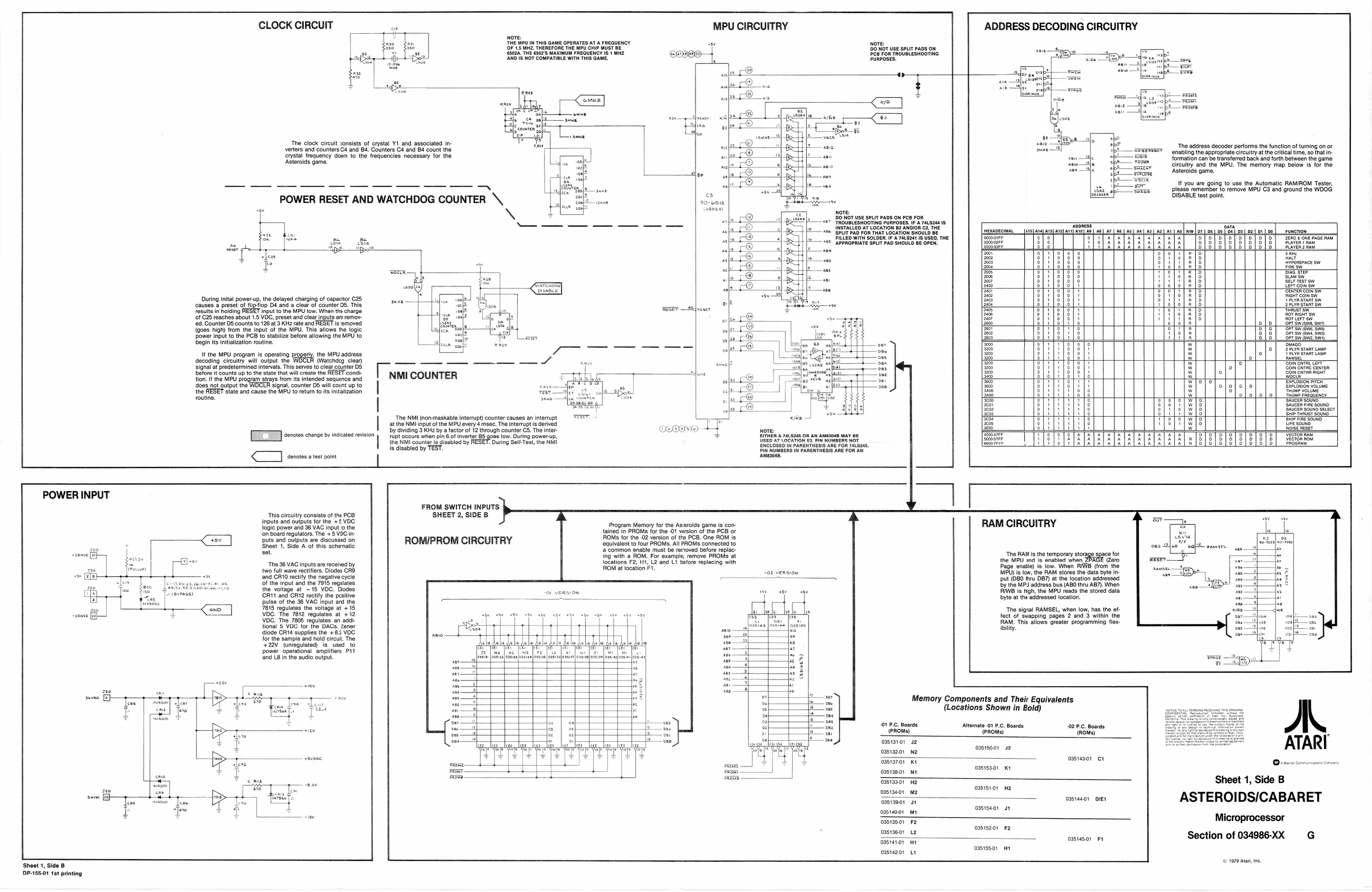
CLOCK CIRCUIT
‘The clock circuit sonsists of crystal Y1 and associated in-
verters and counters C4 and 84. Counters C4 and 84 count the
Crystal frequency davn to the frequencies necessary for the Asteroids game.
POWER RESET AND WATCHDOG COUNTER \,
=
MPU CIRCUITRY
Nore: Do Nor use spurt PADS On Pep FoR TROUBLESHOOTING PURPOSES,
ADDRESS DECODING CIRCUITRY
wept pepe
uring inital power-up, the delayed charging of capacitor C25 sen — cavses's preset of fiptop ba and a cleat of sour D5, This results in holding Input to the MPU low. Whan the charge ‘of C25 reaches about 1.5 VOG, preset and clear inputs ar removfed. Counter D5 counts to 128 a3 KHz rate and RESET is emoved {goes high) from the input of the MPU. This allows fe logic power input to the PCB to stabilize before allowing the MPU to ezine naztion sous ae It he MPU program Is operating properly, the MPU address decoding ercuiyil output the WOELA (Watendg lean a S ae Signal at progetermined intervals. This sores to clear ecunter OS Sloe t counts up to the stato that wil eeate tne RESET cond tion. the MPU program strays from its intended sequince and oes not output the HOGER signal, counter D5 wil count up to the RESET slate and cause ine MPU to return tots intalzaion routine Tw COUNTER
atthe NMI input of the MPU every 4 msec. The interrupt is derived Ea ‘enctes change by indicated revision < enotes a test point ruptoceure wien pin 6 of invertor 85 go the NMI counter a daabled by RESEE is disabled by TEST. low. During power by dividing 3 KHz by a factor of 2 through counter C5. The inter P, ceaas + cy e018
Nore: DONGr use SPLIT PADS ON C8 FOR ‘TROUBLESHOOTING PURPOSES. INSTALLED A LOCATION B2 ANDIOR C2. THE SPLIT PAD FOR THAY LOCATION SHOULD BE FILLED WITH SOLDER IF-A 741820116 USED, THE [APPROPRIATE SPLIT PAD SHOULD BE OPEN:
USED AT LOCATION €2 PI NUMBERS NOT ENCLOSED IN PARENTHESIS ARE FOR 748245,
‘aeboee A ra.s2ea 5 ‘The address decoder performs the function of turning on or ‘enabling the appropriate circuitry at the critical time, so that in- {formation can be transferred back and forth between the game circuitry and the MPU. The memory map below is for the Asteroids game.
I you are going to use the Automatic RAMIROM Tester, please remember to remove MPU C3 and ground the WDOG. DISABLE test point
AE
Savnstanr ow 2PLYA START
Sor tert sa Papen ‘OFTSW She Sw, ‘Spr sw swe sey ‘Spr Sw swe SM
SS urna on
‘Bovoston voclMe
SAGER Souno sector lezeleceslececlesesleses|>oz|>2=2|>2222>2>]>=>2]
FROM SWITCH INPUTS This circuitry consists of the PCB SHEET 2, SIDE B inputs and outputs for the +£ VDC logic power and 38 VAC input 0 the ‘on board regulators, The +5 VOC in- [puts and outputs are discussed on Sheet 1, Side A of this schenatic set
‘The 96 VAC inputs are recened by two full wave rectifiers. Diodes CRO ‘and CR10 rectify the negative cycle Of the input and the 7916 regulates the voltage at -15 VDC. Dodes GRIT and CRI? rectify the pesitive ROMI/PROM CIRCUITRY
pulse of the 36 VAC input ard the 7815 regulates the voltage at +15 VDC. The 7812 regulates at +12 VDC. The 7805 regulates an additional § VOC for the DACS. Zener diode CR14 supplies the +82 VDC for the sample and hold circut, The +22V (unregulated) is used to ower operational amplifiers P11 ‘and LB in the audio output.
Sheet 1, Side B DP-185.01 1st printing Program Memory for the Asteroids game is contained in PROMS for the -O1 version of the POB or OMS for the -02 version of the PCB. One ROM is. equivalent to four PROMS. All PROM connected to ‘common enable must be renoved before replacwith a ROM. For example, remove PROMs at locations F2, Ht, L2 and Lt before replacing with OM at location FT.
an
conee’s) RAM CIRCUITRY
The RAM is the 9 the MPU and ia enabled when 2BAGE (ro Page enable) is low. Whon WE (from the MPU) is iow, the RAM stores the data byte put (DBO fu DB?) atthe location addressed by the MP3 address bus (ABO thru ABT). Wh RIE is High, the MPU reads the stored data byte atthe addressed location.
The signal RAMSEL, when low, has th fect of swapping pages 2 and 3 within the RAM. This allows greater programming flex: ‘ility.
Memory Components and Their Equivalents (Locations Shown in Bold)
01 P.C. Boards Alternate 01 P.C. Boards £2 P.C. Boards PReMs) frac (Roms)
oas1a101 42
| ae | ossiso01 | 42 | ||
| oasiaror | Kt | - | oas1as01 | ct |
| sisi, | we | 03515301 | Ki |
‘casias0r Aa
| ossiseor | M2 | eB: | He | |
| oasi9901 | ot | See | oasiaeo1 | over |
| ini | ossiseor | ot |
oasta507 Fz
| Bosca | ie | ossisz01 | F2 | |
| caster | HT | a2 | osst4s01 | Ft |
oe 0515501 Orrecomncorscinony
Sheet 1, Side B
ASTEROIDS/CABARET
Microprocessor
Section of 034986-XX G
© 1979 Ata, ne.