Dig Dug SP-203 3rd Printing
Dig Dug (rev 2) (Namco, 1982) · Schematic Package · 18 pages · 41 sections · original scan
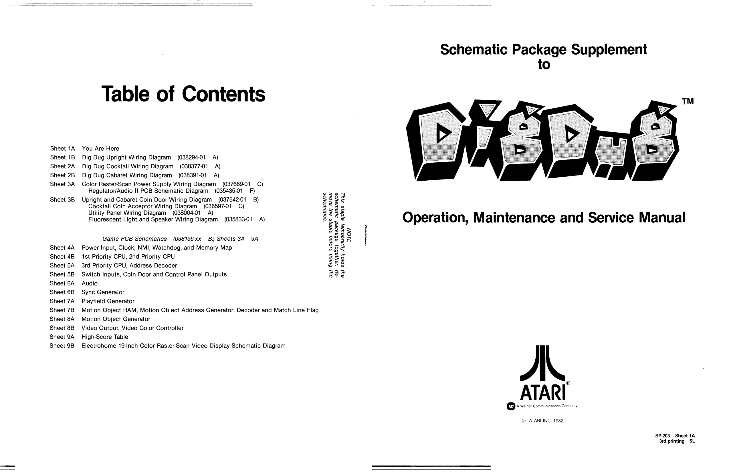
I Schematic Package Supplement to
Table of Contents
Sheet 1A You Are Here Sheet 1B Dig Dug Upright Wiring Diagram (038294-01 A) Sheet 2A Dig Dug Cocktail Wiring Diagram (038377-01 A) Sheet 2B Dig Dug Cabaret Wiring Diagram (038391-01 A) Sheet 3A Color Raster-Scan Power Supply Wiring Diagram (037669-01 C) Regulator/Audio || PCB Schematic Diagram (035435-01_ F) Sheet 3B Upright and Cabaret Coin Door Wiring Diagram (037542-01 B) Cocktail Coin Acceptor Wiring Diagram (036597-01 C) Utility Panel Wiring Diagram (038004-01 A) Fluorescent Light and Speaker Wiring Diagram (035833-01 A) “soNeuayos ay) Bujsn asoyaq ajdejs ay} anow Operation, Maintenance and Service Manual
Game PCB Schematics (038156-xx B), Sheets 3A—9A Sheet 4A Power Input, Clock, NMI, Watchdog, and Memory Map Sheet 4B 1st Priority CPU, 2nd Priority CPU Sheet 5A 3rd Priority CPU, Address Decoder Sheet 5B Switch Inputs, Coin Door and Control Panel Outputs Sheet 6A Audio Sheet 6B Sync Generaior Sheet 7A Playfield Generator Sheet 7B Motion Object RAM, Motion Object Address Generator, Decoder and Match Line Flag Sheet 8A Motion Object Generator Sheet 8B Video Output, Video Color Controller Sheet 9A High-Score Table Sheet 9B Electrohome 19-Inch Color Raster-Scan Video Display Schematic Diagram | ATARI -ay sayjabo} abeyoed ojjewayos ay) spjoy Ajisesodusa} ajdejs siy,
ALON
© ATARI INC. 1982
SP-203 Sheet 1A 3rd printing 5L
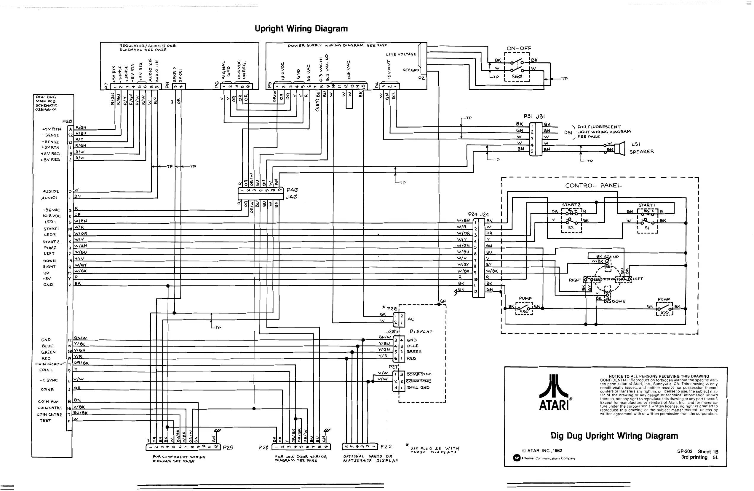
This page is a drawing, shown as the original scan.
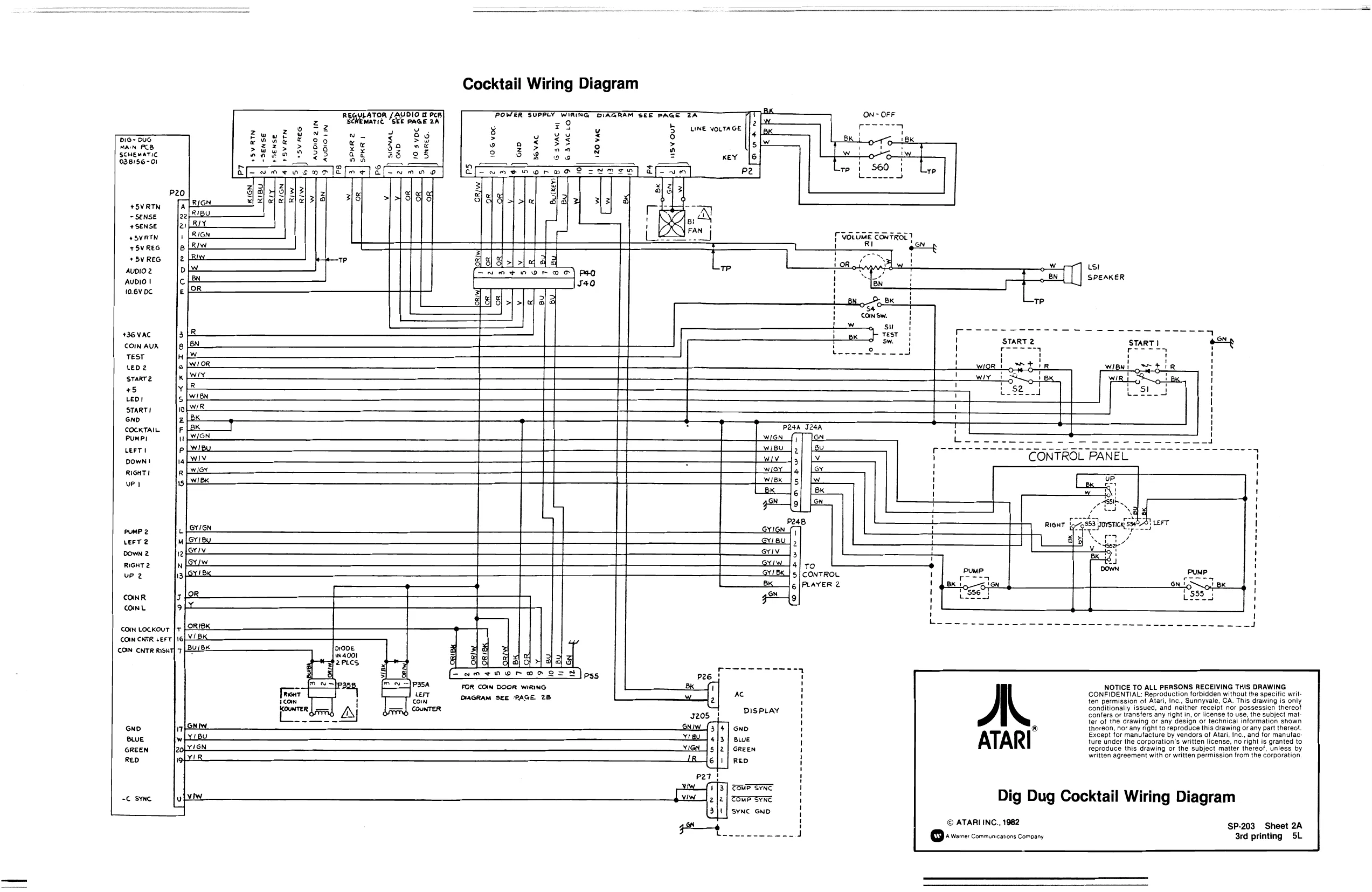
This page is a drawing, shown as the original scan.
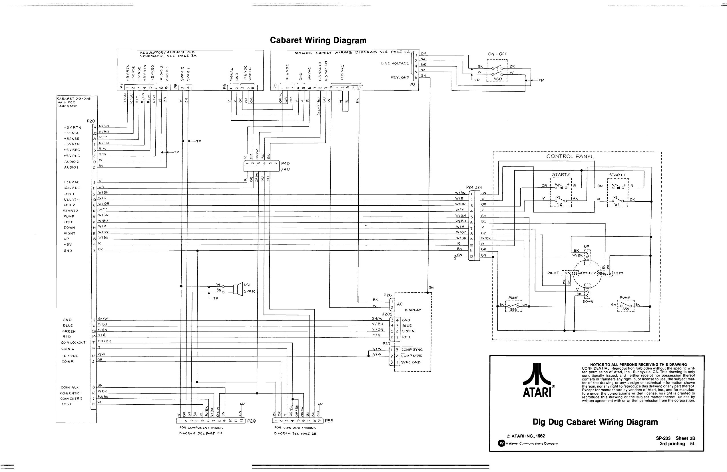
This page is a drawing, shown as the original scan.
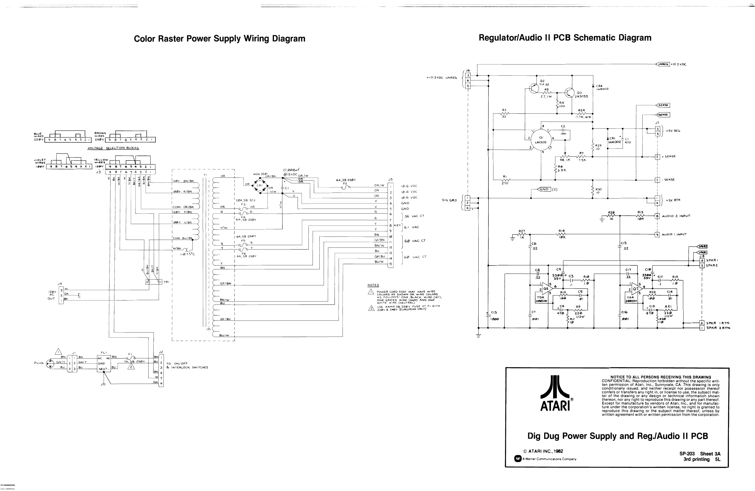
This page is a drawing, shown as the original scan.
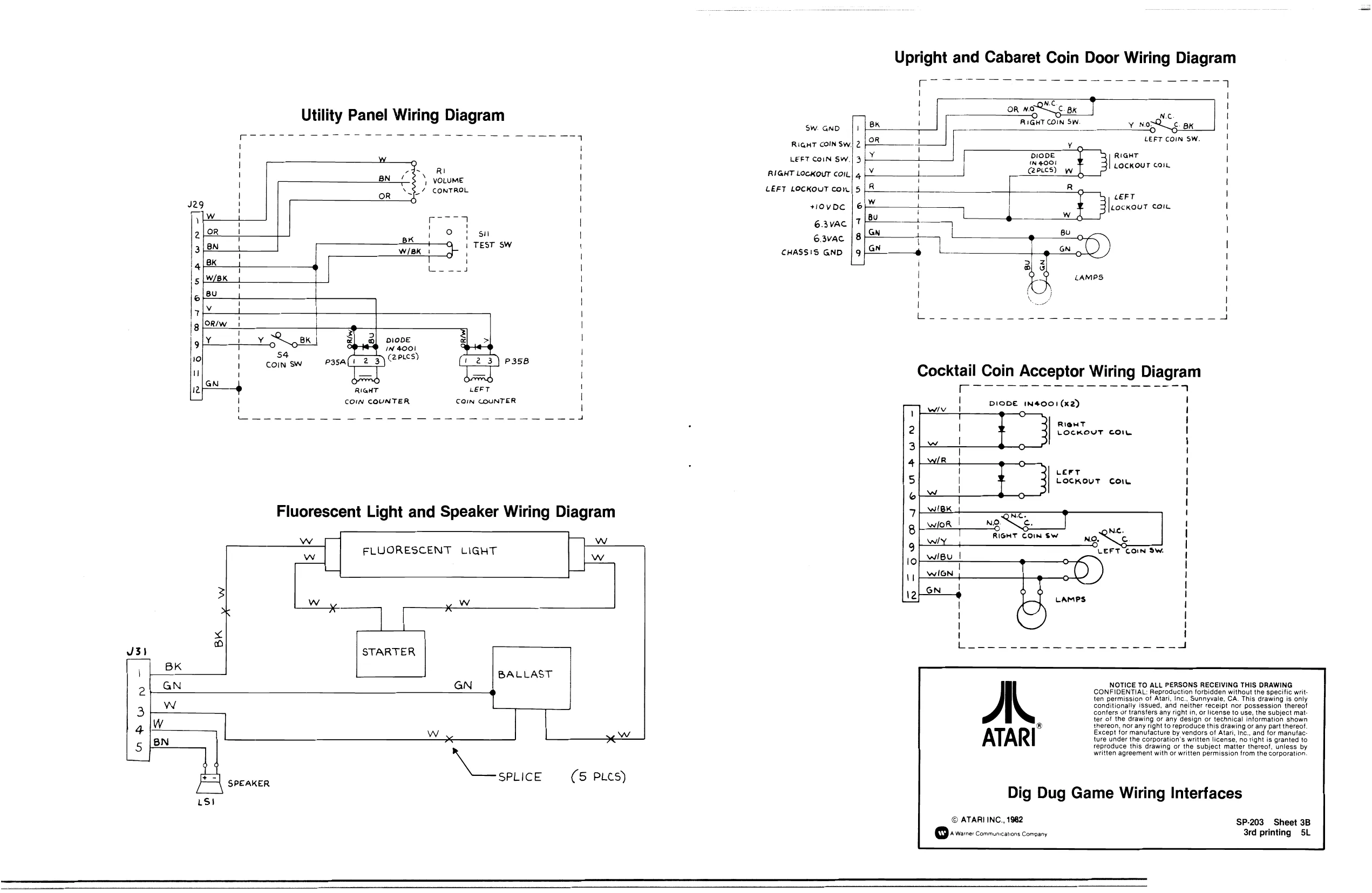
This page is a drawing, shown as the original scan.
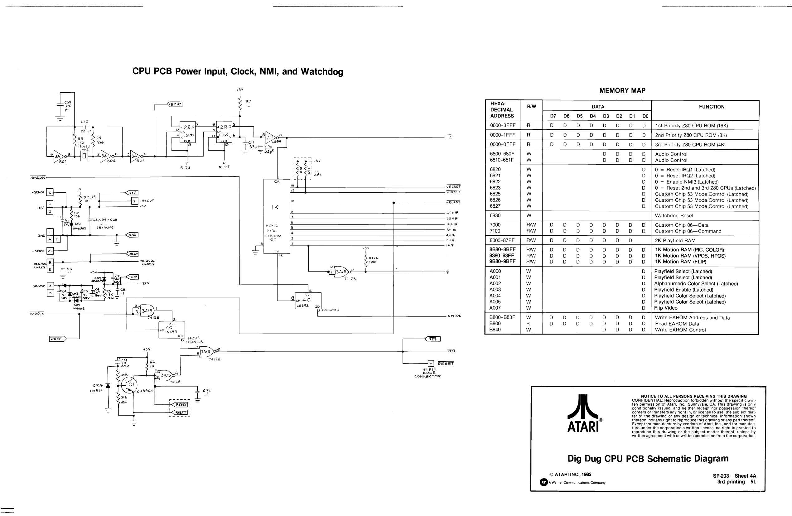
This page is a drawing, shown as the original scan.
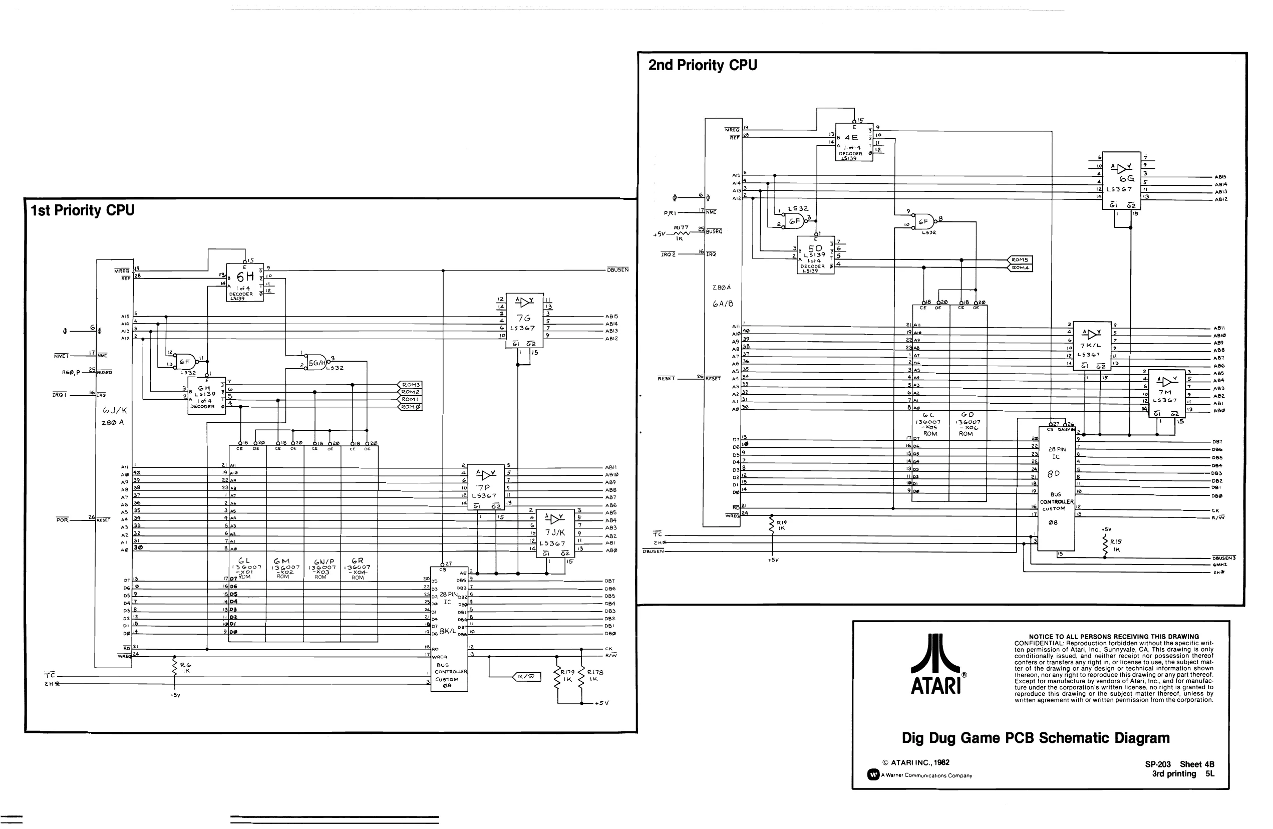
1st Priority CPU
Decor 9} wsi39
oar oes cas oB4 vas ope
e| per vee
las Tw
R19 1K R78, uw
2nd Priority CPU
e 3] ry 7 le 4e 3 rm oT of TE ae DECODER
3. b 385 4 u 3 an el = co decgpeR 3
oC GO 13@007 | 136007 “Kos: ~xoe ROM Rom
AL
ATARI
NOTICE TO ALL PERSONS RECEIVING THIS DRAWING CONFIDENTIAL: Reproduction forbidden without the specific written permission of Atari, Inc., Sunnyvale, CA. This drawing is only conditionally issued, and neither receipt nor possession thereof confers or transfers any right in, or license to use, the subject matter of the drawing or any design or technical information shown thereon, nor any right to reproduce this drawing or any part thereof. Except for manufacture by vendors of Atari, inc., and for manufac: ture under the corporation's written license, no right is granted to reproduce this drawing or the subject matter thereof, unless by written agreement with or written permission from the corporation.
Dig Dug Game PCB Schematic Diagram
© ATARIINC., 1982 SP-203 Sheet 4B 3rd printing SL
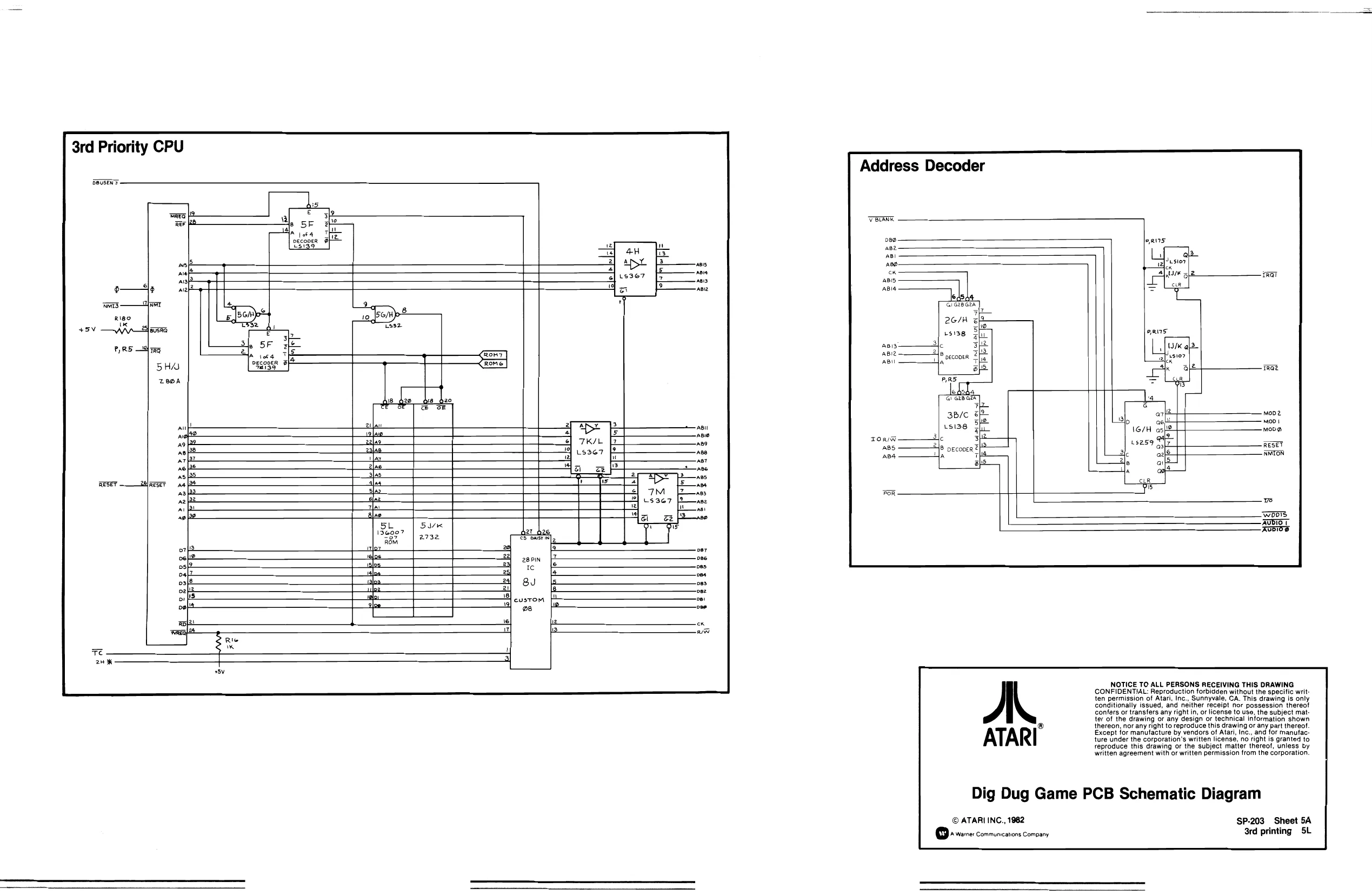
3rd Priority CPU
Address Decoder
le Gree sem
2G/H
usisg
2a borg DECODER Dgcover 3| la mec) SI-1 Mel alu ol si
PAB
le, Gi ate Gis ra se/e @f 15138
c 212 vecooer rs is fw
la e114 wlio ov a
at Sony
2 Ic
r 24 BU
A EPPPEPP
EEE
confers or transfers any right in, or license to use, the subject mat- NOTICE TO ALL PERSONS RECEIVING THIS DRAWING CONFIDENTIAL: Reproduction forbidden without the specific writ ten permission of Atari, Inc., Sunnyvale, CA. This drawing is only conditionally issued, and neither receipt nor possession thereof
ter of the drawing or any design or technical information shown ® thereon, nor any right to reproduce this drawing or any part thereof. Except for manufacture by vendors of Atari, Inc., and for manufac: ture under the corporation's written license, no right is granted to reproduce this drawing or the subject matter thereof, unless by written agreement with or written permission from the corporation.
Dig Dug Game PCB Schematic Diagram
© ATARI INC., 1982 SP-203 Sheet 5A Bo warne: communications Company 3rd printing SL
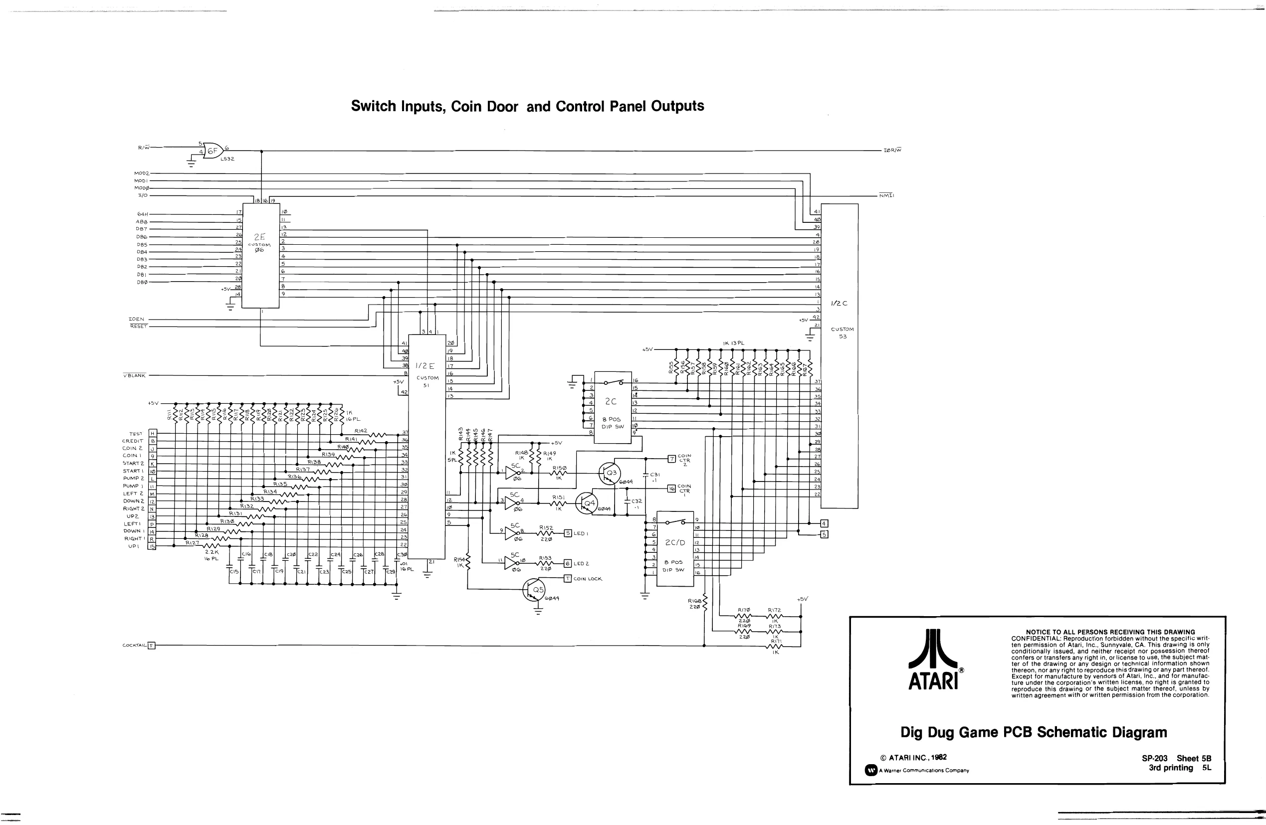
This page is a drawing, shown as the original scan.
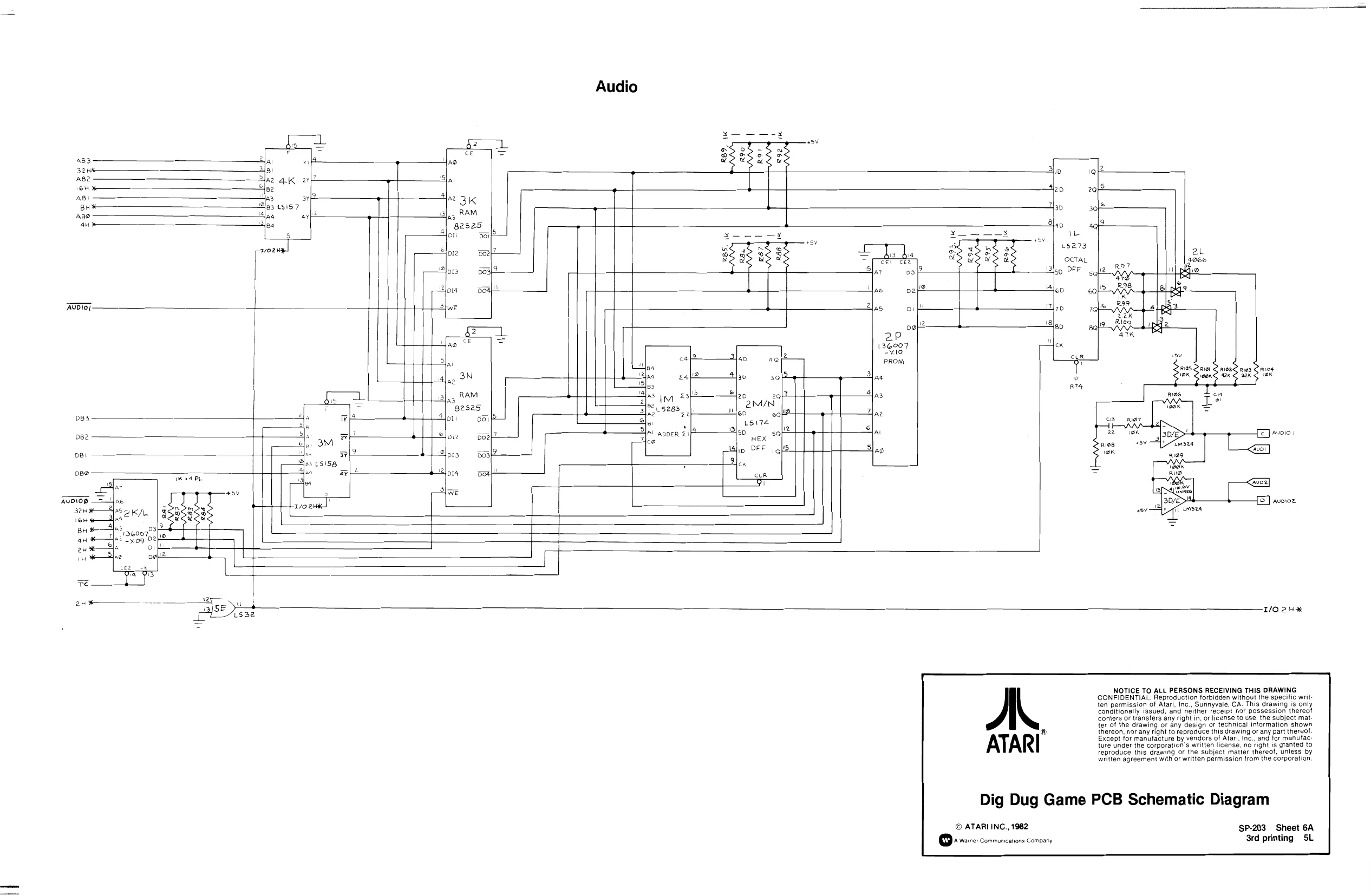
This page is a drawing, shown as the original scan.
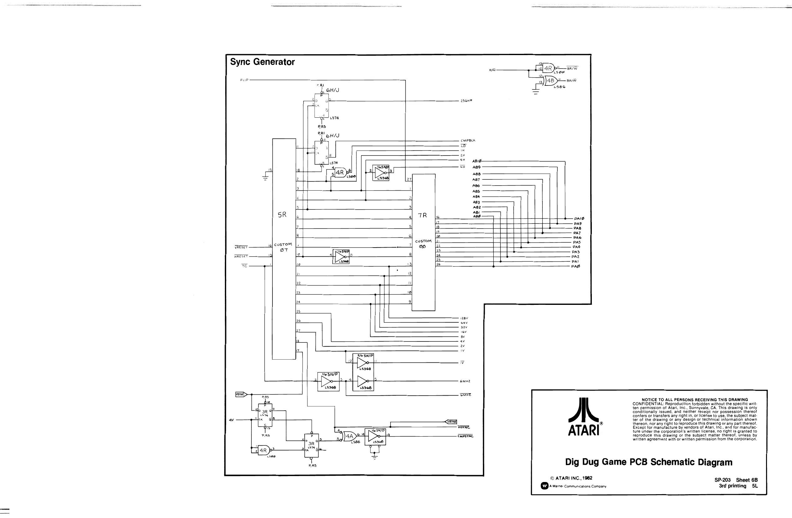
This page is a drawing, shown as the original scan.
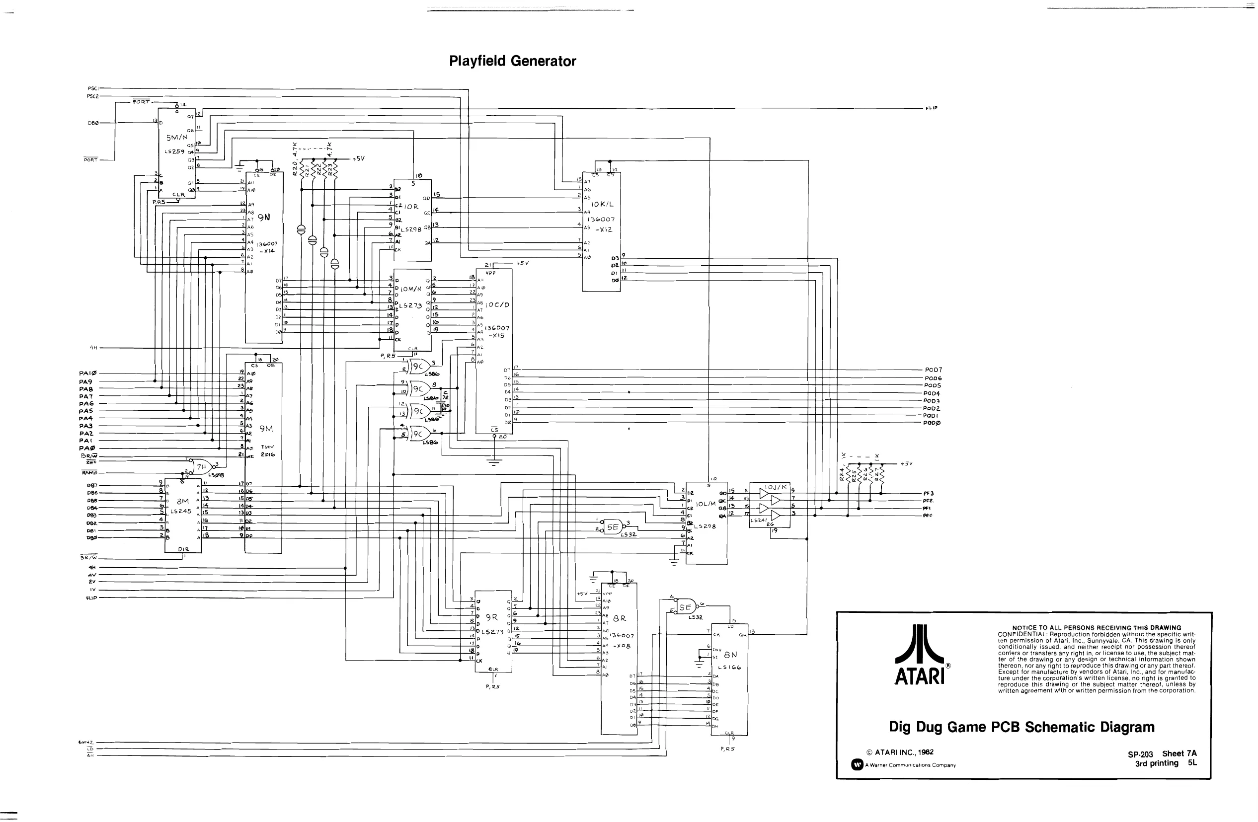
This page is a drawing, shown as the original scan.
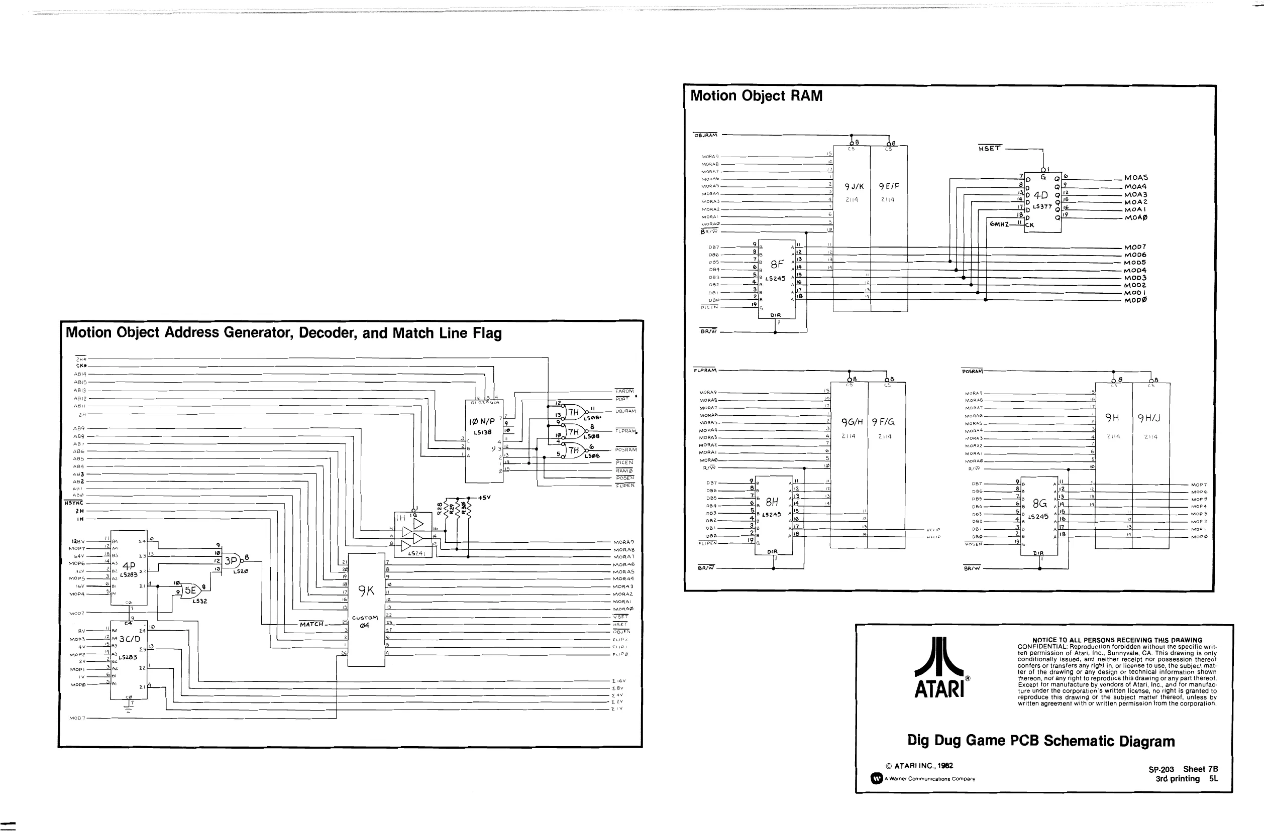
This page is a drawing, shown as the original scan.
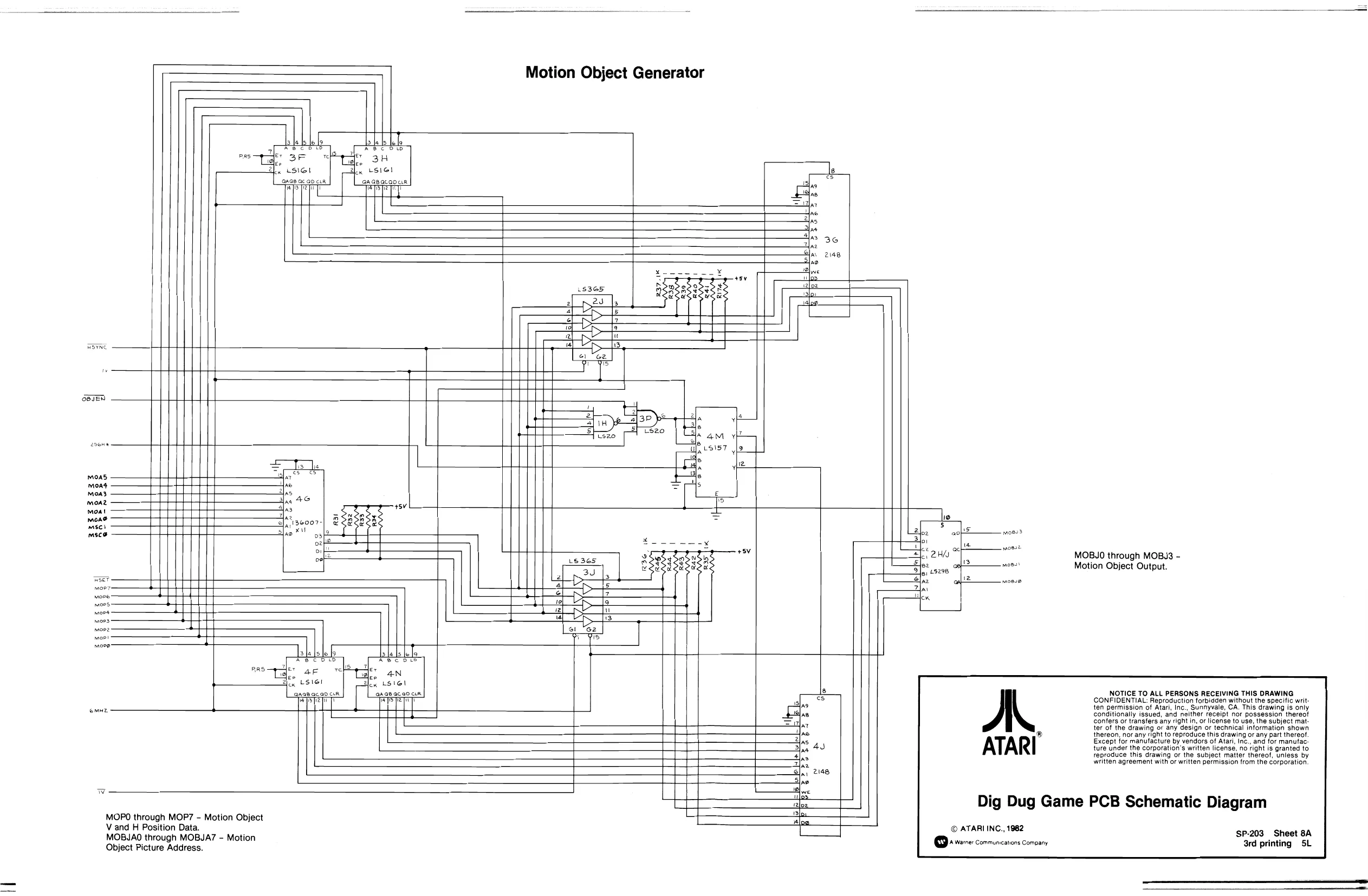
This page is a drawing, shown as the original scan.
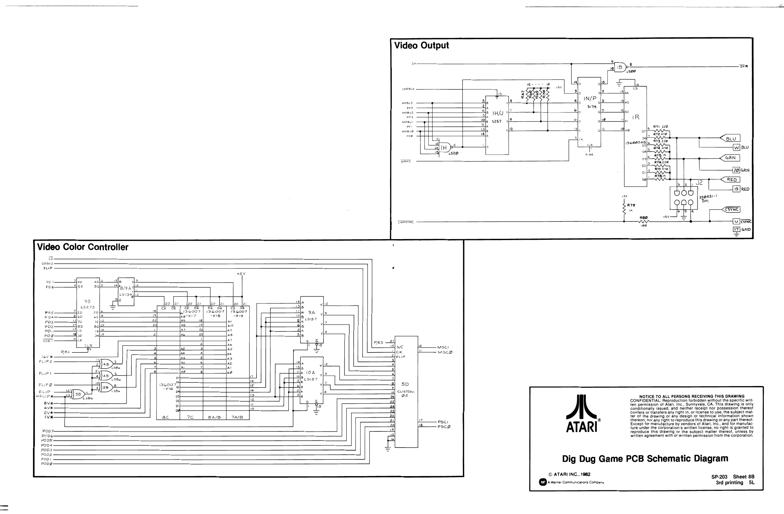
This page is a drawing, shown as the original scan.
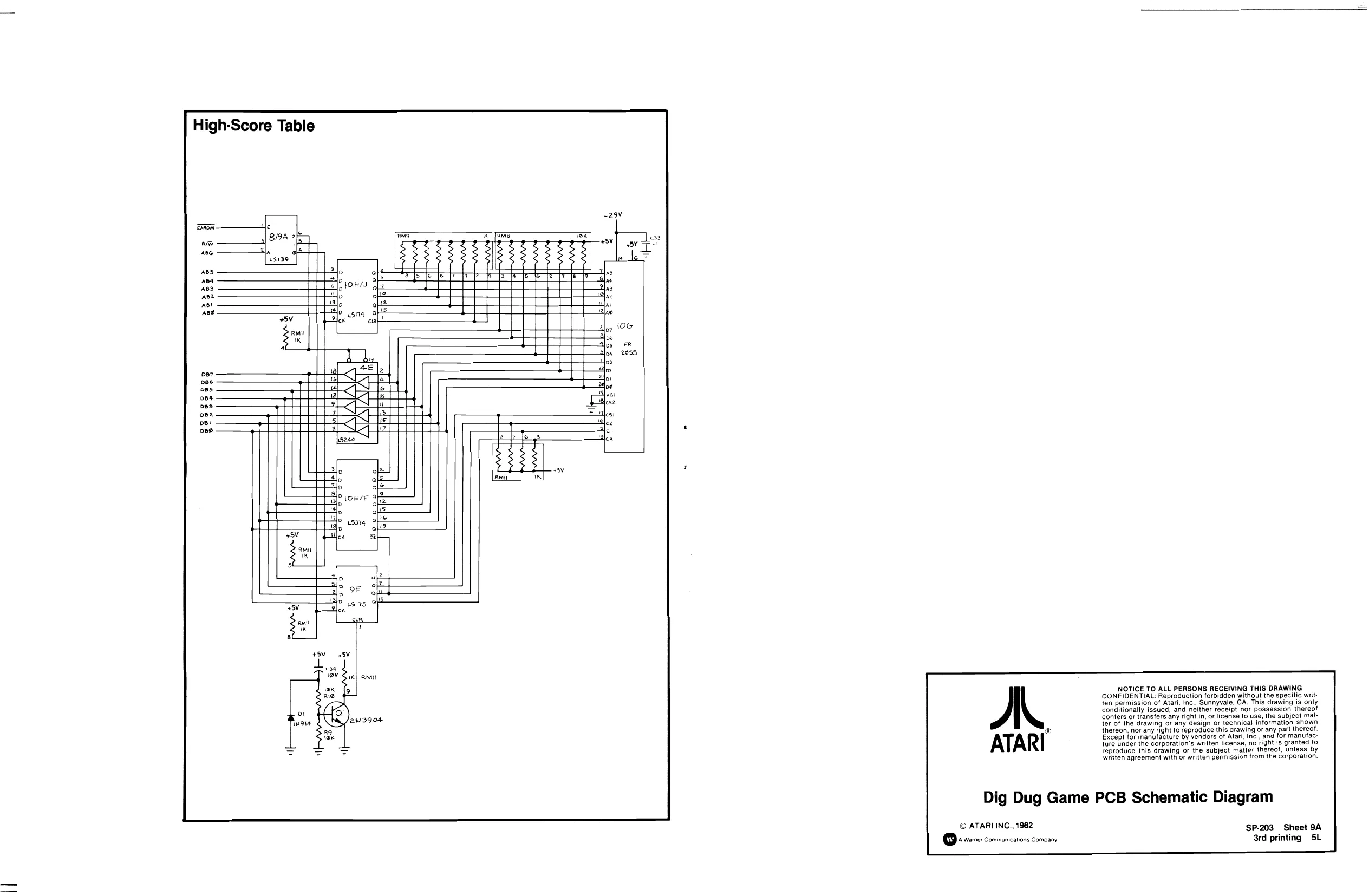
This page is a drawing, shown as the original scan.
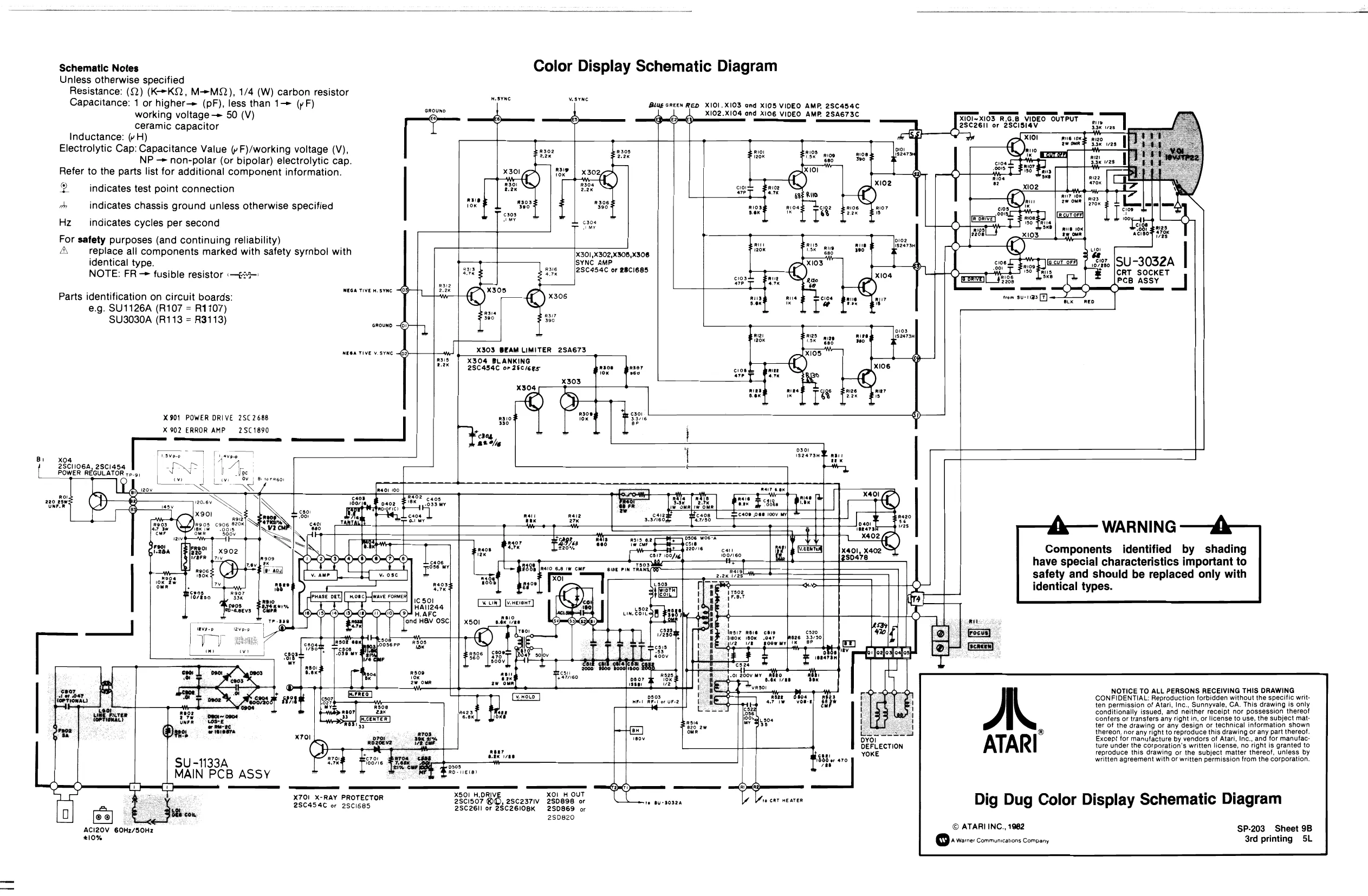
Schematic Notes Unless otherwise specified Resistance: (Q) (K-*KQ, M-MQ), 1/4 (W) carbon resistor Capacitance: 1 or higher-> (pF), less than 1—> (pF) working voltage -> 50 (V) ceramic capacitor Inductance: (vH) Electrolytic Cap: Capacitance Value (»F)/working voltage (V), NP — non-polar (or bipolar) electrolytic cap. Refer to the parts list for additional component information.
2 indicates test point connection
oh indicates chassis ground unless otherwise specified Hz _ indicates cycles per second For safety purposes (and continuing reliability)
identical type.
Parts identification on circuit boards: e.g. SU1126A (R107 = R1107) SU3030A (R113 = R3113)
X901 POWER DRIVE 2SC 2688
X 902 ERROR AMP 2SC 1890
Color Display Schematic Diagram
wesYe vesyac Blug oRteN RED X101.XIO3 ond XI05 VIDEO AMP, 28454 x102.X104 and X106 VIDEO AMP. 2SA673C (0l~X103 R.G.8 VIDEO OUTPUT 28c26ll or 2ScisiaVv Pires
ae 3 Rizo S3e ves
replace all components marked with safety syrnbol with
x305
S30"
X303 BEAM LIMITER 2SA673 x301,X302,X308,X308 SYNC AMP. '2SC454C or BCI685
X304 BLANKING 28C434C oF 25c/6es
x04 2SCI106a, 25c1454 POWER REGULATOR re.9, ° X303 x304 eft |SU-3032A | CRT SOCKET
PCB ASSY J
a Fan, Ecaoe oan 1oov
vaMe
fpuase ott]
X501
SU -1133A MAIN PCB ASSY
XS
ACI20V 6OH2/50Hz 210% eereo Components identified by shading have special characteristics important to safety and should be replaced only with identical types.
X701_ X-RAY PROTECTOR 2SC454C or 2Sc1685 X501_H.ORIVI XO1 251507 @O, 2scza7iv 280898 or 2SC26Il or ZSC26I0BK 250869 or H OUT
280820
ATARI
Dig Dug Color Display Schematic Diagram
© ATARI INC., 1982
WARNING
NOTICE TO ALL PERSONS RECEIVING THIS DRAWING CONFIDENTIAL: Reproduction forbidden without the specific written permission of Atari, Inc., Sunnyvale, CA. This drawing is only conditionally issued, and neither receipt nor possession thereof Confers or transfers any right in, or license to use, the subject matter of the drawing or any design or technical information shown thereon, nor any right to reproduce this drawing or any part thereof. Except for manutacture by vendors of Atari, Inc., and for manufac ture under the corparation’s written license, no right is granted to reproduce this drawing or the subject matter thereof, unless by written agreement with or written permission from the corporation.
‘SP-203 Sheet 9B 3rd printing 5L