Mechanized Attack
Mechanized Attack (World) (SNK, 1989) · Document · 16 pages · 15 sections · original scan
Z
MECHANIZED ATTACK _ ES
OPERATION & SERVICE MANUAL hae
SNK CORPORATION OF AMERICA 246 Sobrante Way Sunnyvale, CA. 94086
TEL: (408) 736-8844 FAX: (408) 736-0446
SNK WARRANTY POLICY
SNK Corporation of America (Seller) warrants to the original purchaser (Buyer) that the components listed beloware free from defects in manufacturing and materials. The warranty period is 90 days, effective the date of original shipment from Seller’s factory.
GAME CPU PCB(S) 90 days POWER SUPPLY SWITCHING REGULATOR ___ 90 days MONITOR ASSEMBLY 90 days GUN ASSEMBLY 90 days
No other parts of Seller’s product are covered by this warranty.
The Seller’s sole responsibility shall be, at it’s option, to repair or replace any warranted item found to be defective during the warranty period. The Buyer’s responsibility shall be to notify the Seller of the defective material, and return it, freight pre-paid, to the place specified by the Seller.
Seller is not responsible for the cost of unauthorized repairs, loss of income, or any charges or losses incurred as a result of the use of this product. Seller does not warrant the suitability of it’s product for a particular application.
This warranty is not applicable for normal wear and tear. This warranty shall be void if inspection of the returned product indicates defect was caused by misuse, or if unauthorized repairs were attempted, or if the item was damaged due to improper handling, shipping, or customer negligence.
TABLE OF CONTENTS
- GENERAL INFORMATION
A.Introduction .
B. Set-up Procedures
C. Dip-Switch Options...
- TECHNICAL INFORMATION
A. Test Mode Operation...
B. Wiring Diagram
- REPLACEMENT PARTS BREAKDOWN
©1989 SNK CORPORATION OF AMERICA 246 Sobrante Way Sunnyvale, CA. 94086
TEL: (408) 736-8844 FAX: (408) 736-0446
- GENERAL INFORMATION
A. Introduction.
Thank you for selecting this fine SNK product. We are sure that it will offer you many years of profitable service. When you purchased this product, you also acquired the support of SNK’s Customer Service Department. We are only a telephone call away, ready to answer any questions pertaining to the operation of our products.
In addition to telephone support, we offer direct mailing of Service Updates and Bulletins simply by returning the Response Card found in the back of this manual. We also use this card to collect feedback from operators of our products to help shape our future products. I will elaborate on several of the features that operators have requested and that have been designed into this game:
e@ELECTRONICS ACCESS DRAWER The Power Supply and Game PCBs (Printed Circuit Boards) are conveniently located on a slide-out drawer in the lower front of the cabinet. The Electronics Access Drawer allows easy access to the these components from the front of the game for adjustments and repairs.
e@SERVICE PANEL The Service Panel contains the Coin Counter, Service Switch, and Test Switch. It is located just inside the coin entry door on top of the cashbox vault.
@PLYWOOD CABINET CONSTRUCTION The cabinet features a plywood bottom floor, with double plywood base walls, and a plywood main cabinet floor. The Electronics Access Drawer front panel is plywood, as are the
three Coin Door mounting panels. This should ensure maximum
protection for the Coin Door and Game Electronics.
e@HEAVY-DUTY PLAYER CONTROLS The players control the action via realistic appearing machine guns. They feature a solenoid activated recoil effect and Optical Sensors for aim control. The guns have been designed to withstand the rough treatment expected from the players. Acomplete breakdown of the replacement parts is included in this manual and may be ordered from your local SNK authorized dealer.
e@CONTROL PANEL SHIELD The control panel finish is protected from cigarette burns and other hazards by a 1/8" clear plastic cover. This should preserve the appearance of the game and protect the underlying wood panel. In addition, a shelf has been installed under the Coin Vault to prevent liquid spills and missed coins from making their way to the game electronics.
e@HI-QUALITY COMPONENTS AND ASSEMBLY This game features the Wells-Gardner 25" monitor, coin door by Coin Controls, and cabinet constructed by Dynamo Corporation, who also assembled the final product. The game PCBs, software, and controls were designed and produced by SNK Corporation in Japan.
B. Set-up Procedures
This game ships from the factory ready for operation. The only assembly required is the installation of the Leg Levelers into the floor of the cabinet. These can be found packed in the cashbox.
The game also arrives with a cardboard assembly protecting the Mirror during shipment. This must be removed from the back of the game. Open the rear access door, pull the horizontal cardboard section straight out, fold up the vertical side pieces, and slide all of the cardboard out the rear of the cabinet. You might want to store the cardboard inside the cabinet directly above the mirror so that you can re-use it when shipping the game.
Refer to the Dip-Switch Options in this manual and make the required changes to suit your location preferences. Adjust the Sound Volume at this time. The Dip-Switches and Sound Volume Control can be found on the Game PCB in the Electronics Access Drawer (see figure 1).
ECTRONICS ACCESS DRAWER
POWER SUPPLY
1/0 XFRAR
SOUND VOLUAE (OF AAX
Cc. Dip-Switch Options
The Mechanized Attack game can be cenfigured to suit the
- preferences of the location where it is to be operated. Please refer to the tables in Figure 2 for the specific options available.
DIPSWITCH 1
CONTINUE. NODE (1COIN TO CONTINUE)”
NUABER OF AAGAZINES —
(ROUNDS OF AMMUNITION }
PLAY PRICING ICOIN/ IPLAY
COIN 1 AND 2COIN/ [PLAY
COIN 2 ICOIN/2PLAY
FREE PLAY
DIPSWITCH 2
LEVEL OF 2 NORMAL
DIFFICULTY 1 EASY
3 HARD
4 HARDEST
ATTRACT AODE YES
SOUND
NEVER FINISH
FREEZE SCREEN
TEST AODE
oo
Re " 35
’ Each time ‘the’ power is applied to the game, the Main CPU
executes a series of testst0'Cistir é that all’ ofi its circuitry is operational. This is referred J ito athe | Power-{
executes a series of testst0'Cistir é that all’ ofi its circuitry is opera checks all program memory R ROMs and RAMS and displays ‘the
status of each. If an error occurs, the test will stop and talsplay a To place the game into ‘manual Test Mode, open the @ein
relevant error condition onthe sc ae ged
Entry door, flip the Test Switch on (up), and turn the game power on. The game will run the Power-Up Self Test, and then display the first test screen. To access the next test screen, press the Player 1 Start button on the left Gun assembly. The various tests are described below: :
- GRID TEST Displays a black screen with 16 vertical and 14 horizontal white lines.
- COLOR TEST Displays 4 boxes that are colored Red, Green, Blue, and White on a Black background.
- SWITCH TEST Displays a grey-white screen with all switch functions listed. As each switch is activated, it’s indicator will change from a"0" toa "1". The screen also displays the spot where the optical sensor in each gun is aimed. The right gun indicator is Violet and the left gun indicator is Green. You should be able to guide the i indicators around the screen. eo
- DIP MODE This screen displays the current Dip Switch options, and shows the status of each dip switch.
- FRONT VIDEO Displays various Front Video images stored in the 4 Meg Roms.
- BACK1 VIDEO Displays a Background image from the Back1 Roms.
- BACK2 VIDEO Displays a Background image from the Back2 Roms.
- SOUND TEST Allows you to select a Sound Code with the Trigger Switch, and generate that sound by pressing the Grenade pushbutton.
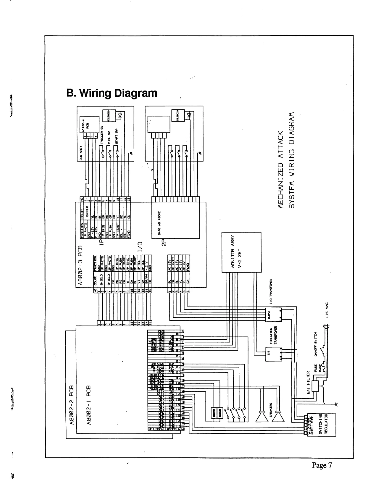
This page is a drawing, shown as the original scan.
This page carries no recoverable text. It is a drawing or a photograph. See the original scan.
- REPLACEMENT PARTS LIST
In the event replacement parts are required for your game, we have included the following section to assist in determining and ordering the proper parts. These parts are available from SNK through any authorized SNK dealer. When ordering replacement parts, please give the complete description of the part as indicated in this section.
©
PS | cay # ©—] 4 n 5 ro @) @ Ter
© 7) L OX = WD pt 9 —_ J @ .C)
FINAL ASSEMBLY 7 Monitor assembly, 25" 8 Game PCB Set , 9 Switching Regulator, 154 1 Mirror 10 Side Decal (R) 2 Gun Assembly 11 Instruction Decal 3 Logo Plex 42 0 PCB 4 Front Glass 5 Side Decal (L) 6 Coin Door assembly 13 1/O Transformer 14 Isolation Transformer 15 Gun Base assembly
GUN ASSEMBLY
GUN HOUSING (L) GUN HOUSING (R) BARREL A BARREL B GUN SIGHT GRIP FRAME A GRIP FRAME B TRIGGER COVER GUN MASK 10 CASE A 11 CASEB 12 SUB SHAFT STOPPER 13 SHAFT SPACER 14 SUB SHAFT 15 SPRING HOOK 16 SIDE BRACKET (R) 17 SIDE BRACKET (L) 18 BOX BASE 19 MAIN SHAFT 20 UP BASE 21 UNDER BASE 22 CAM 23 STOPPER SUPPORT 24 STOPPER COVER 25 OUTER STOPPER 26 BUTTON BRACKET 27 LENS 28 SENSOR PCB 29 MECHANICAL BASE 30 WEIGHT 31 SOLENOID BASE 32 WEIGHT SPRING 33 TRIGGER 34 TRIGGER BASE (L) OONANMEON= 35 TRIGGER BASE (R) 36 SOLENOID ARMATURE 37 WEIGHT SHEET 38 START BUTTON (SS-10R-MB) 39 GRENADE BUTTON 40 RETURN SPRING (KSSC6965) 41 TRIGGER SWITCH (SS-5GL2) 42 TRIGGER SPRING (KSSC6611) 43 RUBBER LEG (C-30-RK) 44 SNAP PIN (SSP-4) 45 BUSHING (80B-1815) 46 BUSHING (80F-1512) 47 SOLENOID (SD 12AA-24-00) 48 SCREW, M5x8 PAN HEAD 49 SCREW, M3x8 PAN HEAD 50 BOLT, M4x25, HEX 51 BOLT, M4x40, HEX 52 BOLT, M4x45, HEX 53 GUN SIGHT (B) (NOT USED) 54 BOLT, M5x35, HEX 55 BOLT, MS5x10, HEX 56 BOLT, MSx12, HEX 57 BOLT, M4x8, HEX, FLAT TOP 58 U-NUT, M12 59 U-NUT, M5 60 NUT, CLOSED TOP, M4 61 WASHER, FLAT, M6 62 WASHER, FLAT, M12 63 WASHER, SPRING, M5
7P Tt
TL
o-9 een © At ©)
aw BL) oo co 3{ \ @® c 5 ie) SNK\ oo . EXAMPLE: po (mmo & = 53) _---4 BOLT NUT, CLOSED TCP MAx25, Mm
ZI o8eg
This page carries no recoverable text. It is a drawing or a photograph. See the original scan.