Asteroids Deluxe Caberat DP-173-1st-02B
Asteroids Deluxe (rev 3) (Atari, 1980) · Drawing Package · 1 pages · original scan
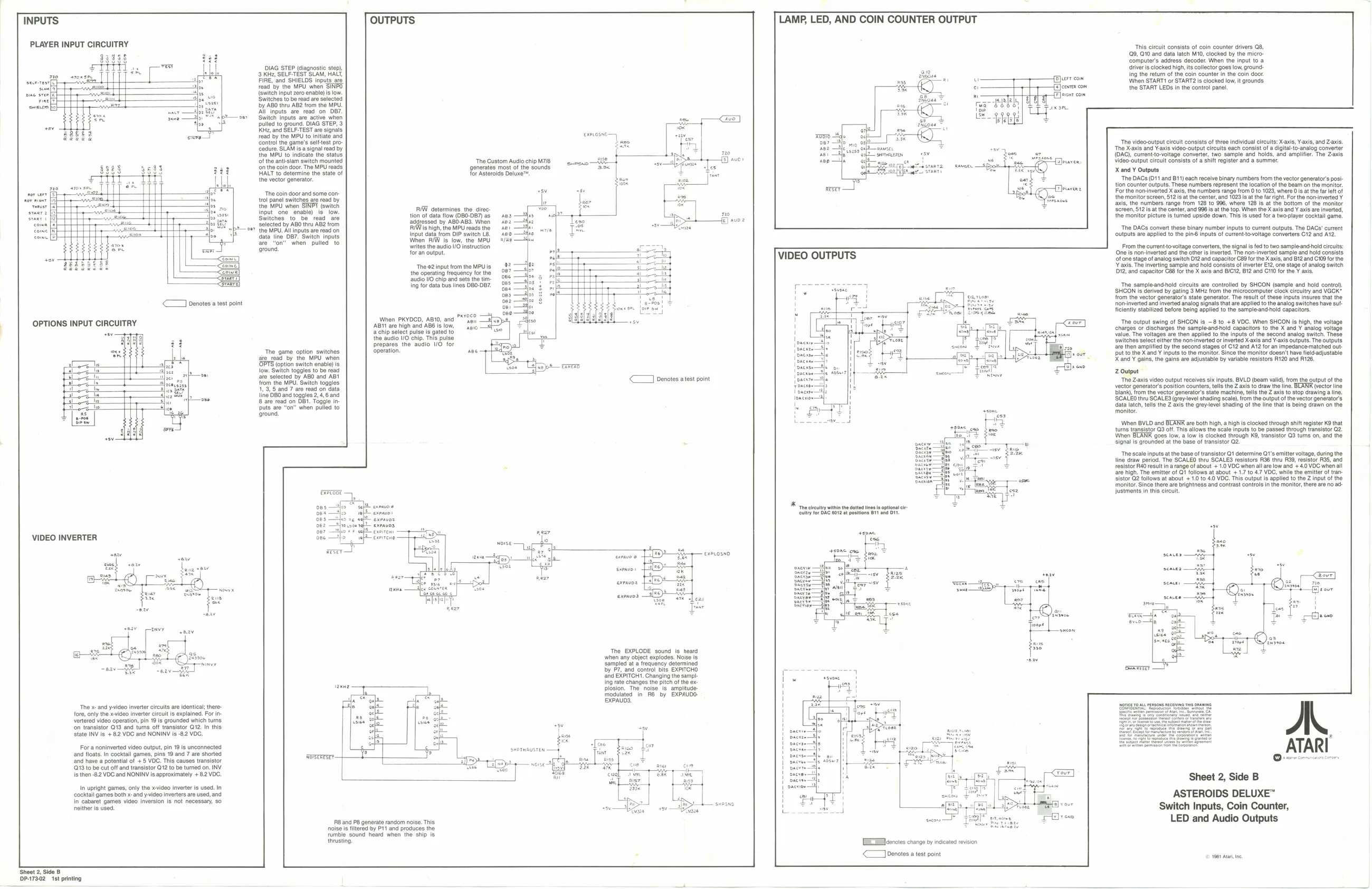
OUTPUTS LAMP, LED, AND COIN COUNTER OUTPUT
INPUTS
PLAYER INPUT CIRCUITRY This circuit consists of coin counter drivers 08, {@9, G10 and data latch M10, clocked by the microcomputer's address decoder. When the input to a drivers clocked high, its collector goes low, grounding the return of the coin counter in the coin door. DIAG STEP (diagnostic step), 3 KHz, SELF-TEST SLAM, HA
| serene | FIRE, ‘and SHIELDS inputs. are | oe | When START! or START2 is clocked low, it grounds | |
| Heel | read ‘by the MPU when SINPO | e | {e]eewrer com | the START LEDs in the control pane! |
| one sree | {Switch input zero enable) is ow. | Hi | berger |
rine Switches to be read are selected = aay
| wae fel | by ABO thru AB2 from the MPU. | na |
All inputs. are read_on OB7. oe ‘Switch inputs are active when pulled to ground. DIAG STEP, 3 He, and SELF-TEST are signals read by the MPU to initiate and control the game's sel-test pro
Cedure. SLAM is a signal read by
the MPU to indicate the status of the ant-siam switch mounted fon the coin door. The MPU reads. HALT to determine the state of the vector generator. carom The video-output circuit consists of three individual circuits: X-axis, Vaxls, and Z-axis. ‘The X-axis and Y-axis video-output circuits each consist of a digital-to-analog converter (OAC), currentto-voltage converter, two sample and holds, and amplifier. The Zaxis Video-output circuit consists of a shift register and a summer X and Y Outputs ‘The DACs (011 and B11) each receive binary numbers from the vector generator's position counter outputs. These numbers represent the location of the beam on the monitor. For the non-inverted X axis, the numbers range from 0 to 1023, where Ois atthe far lett of, the monitor screen, 512s atthe center, and 1023 is atthe far right. For the nonvinverted Y_ axis, the numbers range from 128 to 996, where 128 is at the bottom of the monitor oreen, 612s atthe center, and 996s atthe top. When the X axis and Y axis ae inverted, the monitor picture is turned upside down. This is used for a two-player cocktail game, ‘The Custom Audio chip M7/8 generates most of the sounds for Asteroids Deluxe™
The coin door and some con
nor moet [5 ewe {rol panel switches are read by
| server fap | pp | : | the MPU when SINPI (switch | ||
| smart [ed | : | tH | a | ss | input’ one enable) is ove |
| eer | Switches | to be read are |
IW determines the direc: Pied tion of dataflow (080-087) as ses —Yon addressed by ABO-ABS. When sez —S4uz FIWishigh, the MPU reads the ner 2 Input data from DIP switch La. see —Hhe When R/W is low, the MPU #/n2 —Shw rites the audio 0 instruction for an output selected by ABO thru AB2 from ©} the MPU. All inputs are read on. data line DB7. Switch inputs
| are | “on” | when | pulled to |
‘ground, L ‘The DACs convert these binary number inputs to current outputs. The DACs’ current outputs are applied to the pin inputs of current-tovoltage converters C12 and AT2.
From the currenttovoltage convertors, the signal ised to two samplo-andhod crits: Cone Te nom verted and the eters invert. The non-invertod sample and hold consists VIDEO OUTPUTS Stone stage of analog switen O12 and capacitor C6 forthe X axis and B12 and C10 forthe {axis The inverting sample and hold consist o inverter Ev2 one stage of analog Switch 112, and capacitor C88 forthe X ais and BIC, B2 and C10 forthe Y axis,
‘The ©2 input from the MPU is
the operating frequency for the Peereeee ‘audio VO chip and sets the tim- 3
| ing for data bus lines 080-087. | 4 | r--- | ‘The sampleand-nold circuits are controlled by SHCON (sample and hold conto) |
| H | ie | ‘SHCON is derived by gating 3 MHz from the microcomputer clock circulty and VGGK" |
3 from the vector generators state generator. The result of these inputs insures that the
| <7 enotes a test point | 8 | norinvated andinvered naogsgal ia are applied | halo gulch | ave su- | ||
| ' | ilenty st | re being applied to the sampleandthold | capacitors. | |||
| Wen PKYDOD, ABIO, and "Agi | i | ‘The output swing | of SHOON is -8 to +8 VOC. When SHCON is high, the volt | |||
| OPTIONS INPUT CIRCUITRY | ABI are high and ABB | iow, | aio | ' | charges of discharges the sampteandold capacitors tothe X and | anaiogvatage |
| 4 chip select pulse is gated to | . | ' | Value. The voltages are then applied to the inputs of the second | analog switch. These | ||
| the aucio UO chip, Tis pulse | : | Ce | eee | Switches select elther the non-iverted or inverted X-axis and Y-axis outputs. The outputs | ||
| Prepares the audio NO | for | fro | ea | are then amplified by the second stages of C12 and A12 for an impedance:matched out: | ||
| ‘The game option switches | operation. | nee | se | Senet] | put to the X and ¥ inputs to the monitor. Since the monitor doesn't have feldadjustable | |
| a ged ihe MPU wen | ts | Sera | . | X and ¥ gains, the gains are adjustable by variable resistors R120 and R128. | ||
| low. Switch toggles to be read | | paease— | Zep | ||||
| af selected by AD and AB | < J | enotes atest point | \ pace) | ‘Tho Z-axls vdeo output receives six inputs. BVLO (beam valid), from the output of the | ||
| from Be | MPL | Outi Dagles | vector generato’s position counters, tells the Z axis to draw the line. BLANK (ector line |
line DBOend opotee 2a, Bnd blank, from the vector generators state machine, tells the Z axis to stop drawing alin. Hediedap ty cageemengh SCALEO thru SCALES (grey-level shading scale), fom the output of the vector generators data latch, tells the Z axis the grey-level shading of the line that is being drawn on the puts are “on” when pulled 10 monitor. ‘ground, When BVLD and BLANR are both high, a high s clocked through shift register K9 that turns transistor G3 off. This allows the scale inputs to be passed through transistor Q2. When BLANK goes low, a low is clocked through K9, transistor Q3 turns on, and the signal is grounded at the base of transistor Q2. ‘The scale inputs at the base of transistor Q1 determine Q1’s emitter voltage, during the line draw period. The SCALEO thru SCALES resistors R36 thru R99, resistor R35, and resistor RAO result in arange of about + 1.0 VOC when all are low and + 4.0 VDC when all are high. The emitter of Qt follows at about + 1.7 to 47 VOC, while the emitter of tran- Sistor Q2 follows at about + 1.0 to 4.0 VOC. This output is applied to the Z input of the ‘monitor. Since there are brightness and contrast controls in the monitor, there are no adjustments in this circuit, be
| es —Aso | sep | xmas | * ‘The circultry within the dotted lines is optional cir- |
| VIDEO INVERTER | B62 | ep exeirene — | =. |
40K, ies Be xeL0 sno ee bean = fc ala exrnun @ ioe
| me | * | exo J | 4 | seater |
| Te | ne | exrnvos | sence: |
axve —ih
cme dese
seav Canvy
The EXPLODE sound is heard
when any object explodes. Noe is Ing rate changes the pitch ofthe ex
sampled at a frequency determined
| by P7, and control bits EXPITCHO | a | RTT |
and EXPITCH1. Changing the sampl-
Is then -&2 VDC and NONINV is approximately + 8.2 VDC. oto Sheet 2, Side B r
a plosion. The noise is amplitude- p modulated in R6 by EXPAUDO- 1
| L- | ! | EXPAUDS. | \ | ||
| ‘Te x-and y-video inverter circuits are identical there- | fe | \ | |||
| fore, only the video Inverter circu is explained. For in | IE | ! | |||
| verted video operation, pin 19 is grounded which turns | i | i | : | = | |
| fon transistor O79 and turns off transistor Q'2. In this | af | ' | aang | ||
| State INV is +82 VOC and NONINV is -82 VDC. | Sie | ' | = | E | |
| fe | ' | Saseoe | one | ||
| For a noninverted video output, pin 19 is unconnected | : | i | Seaaos | = | ATARI |
| and floats. in cocktail games, pins 19 and 7 ae shorted | wor | dg | ' | ALANIS | |
| She haves poentl ofr YOO. Tle causes tarwior | sore | = | He | eee | OQ errr smcssoncoon |
| {G13 tobe cutoff and transistor G12 to be tured on. INV | ae | | | stoma |
\
L
| In | upright | ly the x-video inverter is used. In | accion} | ra |
| cockal games bth x and yio Ivetrs are Use, and | oy | ASTEROIDS DELUXE’ |
in abet games vdeo version fs not necaeeay ! i
| natteris sed | = Met | nesenang | se | ae | 7 | Switch Inputs, Coin Counter, |
RB and P8 generate random noise. This TR ithe LED and Audio Outputs noise teed oy #41 and produces te meas Tumde sound heard when he hp is
<—wnetes atest point st tne
Sheet 2, Side B DP-17302 st printing