Centipede Cocktail DP-188-1st-02A
Centipede (revision 4) (Atari, 1980) · Drawing Package · 1 pages · original scan
From MPU ‘Address Bus Sheet 1, Side 8
From Sync Generator Sheet 1, Side B
Playfield Address Selector
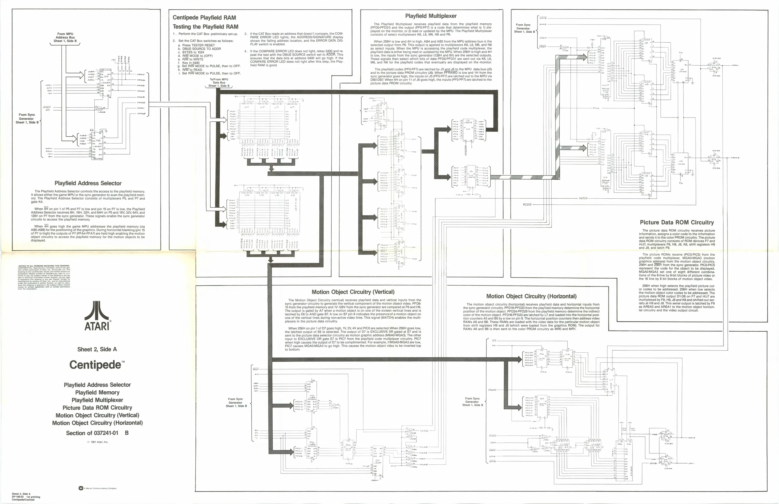
‘The Playfield Address Selector controls the access to the playfield memory. {allows either the game MPU or the sync generator to scan the playfield mem ony. The Playtield Address Selector consists of multiplexers PS, and P7 and gate Ke. nen Fon pin 1 of PS and P7 i fw and pn 15 oP low, the Ply Adeross Selector receives 6, 16H, 28H, and StH on Po and 18, 22,64, and {28V on PY from the syne generator. These signals enable he sync generator iruite to aceaes the payed memory
nen 2H goes high the game MPU addresses the playfield memory (via
‘AB0-ABS) for the positioning ofthe graphics. During horizontal blanking (pin 15
‘of P7 is high) the outputs of P7 (PFA4-PFA7) are held high enabling the motion object circuitry to access the playfield memory for the motion objects to be displayed.
Centipede Playfield RAM Testing the Playfield RAM
- Perform the CAT Box preliminary setup. 3.
2. Set the CAT Box switches as follows:
ross TESTER RESET DBUS SOURCE TO ADDR BYTES to 1024 4 |. IW MODE to (OFF) AW to WRITE Key in 0400 Set FIW MODE to PULSE, then to OFF. RIWto READ ‘Set RIW MODE to PULSE, then to OFF, TolFrom MPU ‘Data Bus ‘Sheet 1, Side 8
A. ATARI
Sheet 2, Side A
Centipede”
Playfield Memory Playfield Multiplexer Picture Data ROM Ci ircuitry Motion Object Circuitry (Vertical) Motion Object Circuitry (Horizontal)
Section of 03724101 B
© 1961 At, ne.
Sheet 2, Sida A DDeNe862 et printing Centipedercockta The Playfield Multi
It the CAT Box reads an address that doesn't compare, the COM: PARE ERROR LEO lights, the ADDRESSISIGNATURE display shows the failing address location, and the ERROR DATA IS- PLAY switch is enabled. It the COMPARE ERROR LED does not light, rekey 0400 and repeat the test with the DBUS SOURCE switch set to ADDR. This, ‘ensures that the data bits at address 0400 will go high. ifthe ‘COMPARE ERROR LED does not light after this step, the Playfield RAM is good.
picture data PROM circuitry. [ Playfield Multiplexer
er receives playfield data from the playfield memory (PFDO-PFDS1) and the output (PFO.PF7) is a code that determines what is 1) dis Ge played on the monitor, or 2) read or updated by the MPU. The Playfield Multiplexer Consists of select multiplexers KE, L6, M6, NB and PS. When 256H is low and 4H is high, AB4 and ABS from the MPU address bus is the selected output from PS. This output is applied to multiplexers KE, L6, M6, and N6 as select inputs. When the MPU is accessing the playt playfield datais either being read or updated by the MPU. When 256H is high and 4H Is low, the inputs from the sync generator (128H and 8V) are the selected outputs. These signals then select which bits of data PFOO-PFDS1 are sent oul via KB, LB, MB, and N6 for the playfield codes that eventually are displayed on the monitor.
“The playfield codes (PFO-PF7) are latched by JS and J6 to the MPU data bus (J5) and to the picture data PROM circuitry (J6). When ‘syne generator goes high, the inputs on J (PFO-PF7) are latched out to the MPU via 'DB0-DB7. When 4H on pin 11 of J6 goes high, the inputs (PFO-PF7 are latched to the From Syne | soe — Shoot 1, Side 8
‘code multiplexer, the
Is low and 1H from the
From Syne Generator ‘Sheet 1 Side B Motion Object Circuitry (Vertical)
The Motion Object Circuitry (vertical) receives playfield data and vatcal inputs from the ‘syne generator circuitry to generate the vertical component of the motion object video. PFO8- 15 rom the playfield memory and 1V-128V from the sync generator are compared at F6 and H6. ‘The output is gated by A7 when a motion object is on one of the sixteen vertical lines and is latched by E6 to AND gate 7. A low on B7 pin 8 indicates the presenceof a motion object on ‘one of the vertical lines during non-active video time. This signal (MATCH) enables the mult plexers in the picture data circuitry.
When 256H on pin 1 of 07 goes high, 1V,2V, 4V and PICO are selected. When 256H goes low, the latched output of E8 is selected. The output of D7 is EXCLUSIVE OR gated at E7 and is sent to the pictute data selector circuitry as motion graphic address (MGAO-MGA3). The other input to EXCLUSIVE OR gate E7 is PIG7 from the playfield code multplexer circuitry. PIC ‘when high causes the output of E7 to be complimented. For example, it GAO-MGA3 are low, PIC7 causes MGAOMGAS to go high. This causes the motion object video to be inverted top to botiom, Motion Object Circuitry (Horizontal)
‘The motion object circuitry (horizontal receives playfield data and horizontal inputs from the sync generator cicuitry. PFD16-PFD23 from the playfield memory determine the horizontal position of the motion object. PFO24-PFD29 from the playfield memory determine the indirect ‘color of the motion object. PFD16-PFD23 are latched by L7 and loaded into the horizontal post tion counters AS and B5 by a low on pin 9. The horizontal position counters then address video RAMS A6 and B6. These RAMS are loaded with the video data forthe particular motion object from shift registers H9 and J9 (which were loaded from the graphics ROM). The output for AMS AB and 86 is then sent to the color PROM circuitry as MAO and MRI. Picture Data ROM Circuitry
The picture data ROM circuitry receives picture Information, assigns a color code to the information and sends i to the color PROM circuitry. The picture data ROM circuitry consists of ROM devices F7 and HW, multiplexers F8, HB, J8, KB, shift registers HO ‘and J9, and latch F9.
The picture ROMs receive (PICO-PICS) from the playfield code multiplexer, MGAO-MGAS (motion (graphics address) from the motion object circuitry, 256H and 256A from the sync generator. PICOPICS represent the code for the object to be displayed. MGAO-MGA3 set one of eight different combina: tions of the ine by &-it Blocks of picture video of the 16 line by 8 bit Blocks of motion object video.
256H when high selects the playfield picture col or codes to be addressed. 256H when low selects the motion object color codes to be addressed. The picture data ROM output D1-D8 on F7 and HNJ7 are ‘multiplexed by F8, H8, JB and KB and shifted out serlally at H9 and J8. This serial output is latched by FO ‘as AREAO and AREAL to the motion object horizon {al ciroulty and the video output eircult