Missile Command Cocktail DP-152-1st-01A
Cocktail Missile Command (Atari) · Drawing Package · 1 pages · original scan
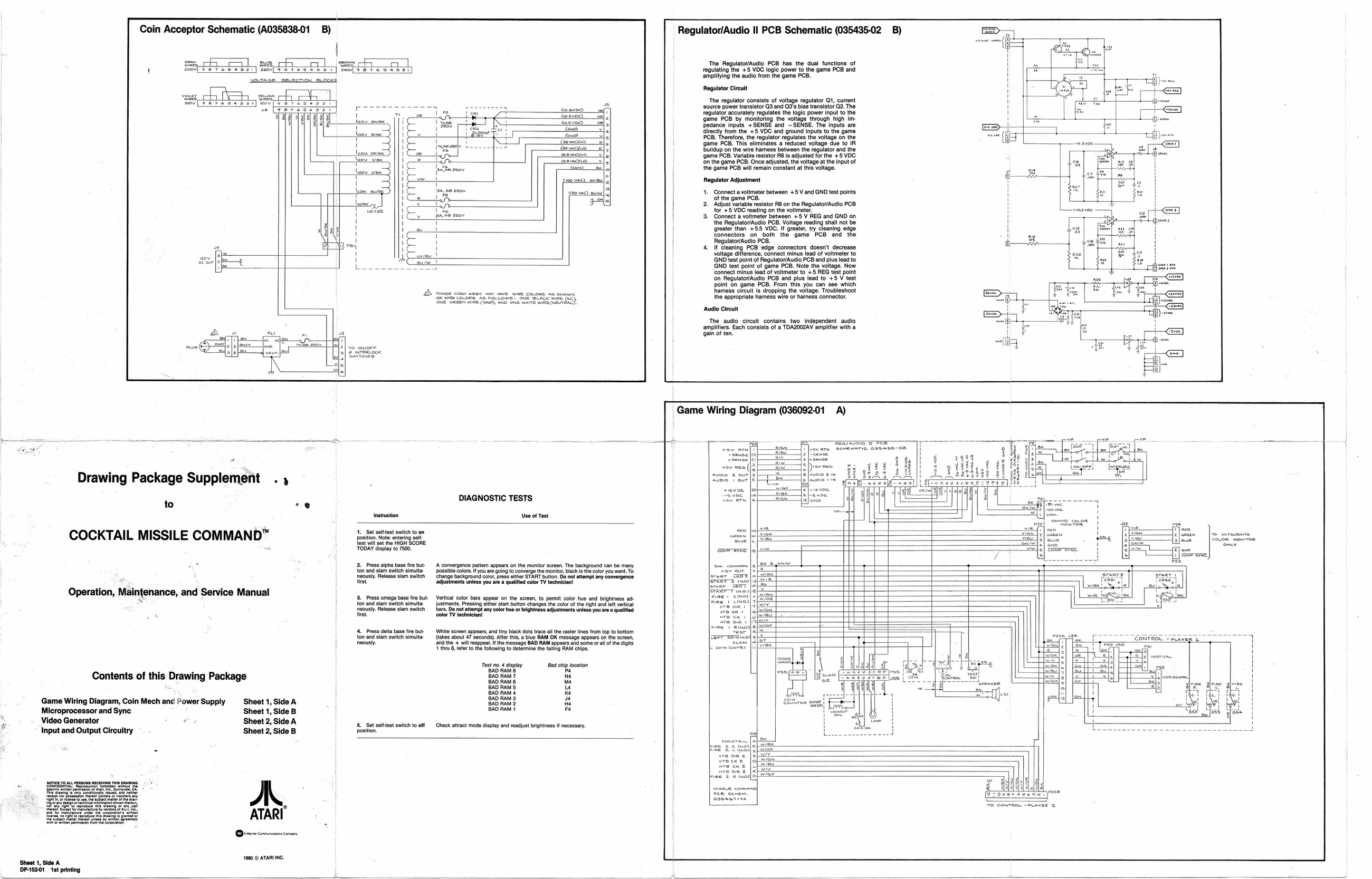
Coin Acceptor Schematic (A035838-01 B) Regulator/Audio II PCB Schematic (035435-02 B)
sec os CR) eee The Regulator/Audio PCB has the dual functions of Safe BH Bee regulating the +3 VDG logie power to the game PCB and amplitying the audio from the game PCB. Regulator Circuit Dae on eereay] wv ‘The regulator consists of voltage regulator Q1, current source power transistor G3 and G's bias transistor G2. The regulator accurately regulates the logic power input to the fe.8vec) {game PCB by monitoring the voltage through high im: edance inputs +SENSE and SENSE. The inputs are
| eo | wine | ene | Girectly from the +5 VOC and ground inputs to the game |
| aa | Lan | OB. Therefore, the regulator regulates the voltage on the | |
| ' | auth | ‘game PCB. This eliminates a reduced voltage due to IR |
' anata —e| Buildup on the wire harness between the regulator and the
| je Sa | esac | ‘game PCB. Variable resistor RB is adjusted for the +5 VOC |
| laow vine | NT | fon the game PCB, Once adjusted, the voltage at the input of |
sen au} the game PCB will remain constant at this voltage. Gosvesd
co vac) ei Regulator Adjustment
| fotovse) | 1. | Connect a voltmeter between +5 V and GND test points: |
‘of the game PCB.
- Adjust variable resistor R8 on the Regulator/Audio PCB for +5 VDC reading on the voltmeter.
- Connect a voltmeter between +5 V REG and GND on the Regulator/Audio PB. Voltage reading shall not be ‘greater than +55 VDC. If greater, try cleaning edge connectors on both the game PCB and the | Regulator/Audio PCB. | 4. If cleaning PCB edge connectors doesn't decrease voltage difference, connect minus lead of voltmeter to ‘GND test point of Regulator/Audio PCB and plus lead to GND test point of game PCB. Note the voltage. Now connect minus lead of voltmeter to +5 REG test point ‘on Regulator/Audio PCB and plus lead to +5 V test point on game PCB. From this you can see which cota cops nai tn tne tek Sound. harness circult is dropping the voltage. Troubleshoot Serres cocone, ve execowe tone. packs we ces the appropriate harness wire or hamess connector. ‘Audio Circuit ‘The audio circuit contains two independent audio amplifiers. Each consists of a TOAZOG2AV amplifier with a ‘gain of ten.
Game Wiring Diagram (036092-01 A)
= i mare Ee
_ +5y neo (| Drawing Package Supplement . fee vol DIAGNOSTIC TESTS Ta ahs to -e@ Instruction Use of Test COCKTAIL MISSILE COMMAND™ emcee = is ree {cot wil st the HIGH SCORE owe
fine cine]
| fare as | aca | = | a | = | ||
| 4% | 2. Press alpha base fire but- | A convergence pattem appears on the monitor screen. The background can be many. | swe common | a | — | ||
| Se eg rel | arte | eet | teeter trent | | | cose | ft |
| SS SSoe | Seon ere ee eee | eerie. | = | |||
| P= | Soe | ere vena | omeelh | ane |
Operation, Mainten: frases le Se
| peration, | Maintenance, and Service Manual | 4. | ae omg base fr but | Vaca! color tar appar on hat, 0 pat color hue and ghia a | wine etioi | = |
{on and slam switch simulta. justments. Pressing ether start button changes the color ofthe ight and elt vertical
| fcoush Release slam sten | bar Donat attempt an color he or ighinessajsimene ios you es Guliod | wegen | |
| fst | ceior Vtech! | wre ex's | |g |
- Press dlta base fe but: White screen appears, and tiny black dots trace al the raster lines from top to bottom one t Soe]
| ton and slam such mute. | Rakes about | seconde) Aor tho, lve RAM OK message appere en the ere, | eeer-earsoy 9 | rian |
| menus | fhe + wil appear | he message BAD RAM appears an orn oa ofthe gts | see |} | : |
| fears he owing To cetemin the alr RAM coe | J concerns | H |
Tos 4 poy 2x4 hp eaton A
| Contents of this Drawing Package | BAD RAM? | ue | H |
BAD Rams u BAD Raw & rt
| Game Wiring Diagram, Coin Mech anc Power Supply | Sheet 1, Side A | BAD Raw 2 | i | |||
| Microprocessor and Sync | Sheet 1, Side B | BAD RAM | iat | |||
| s | Video Generator | ¢ | Sheet 2, Side A | wl | rect | od ig |
| é | rout ntl Output Cocadtay | eeuen | 5, get soot | tent tt Catt mode dpa ad ait anti | reena, |
<a aoe re emcee 6 Ga aaa Siar ATARI Oommen cory
10 © ATARING Sheet 1, Side A DP-15261 1st printing