Chase HQ Electrocoin Version
Chase H.Q. (World) (Taito Corporation Japan, 1988) · Manual · 27 pages · 16 sections · original scan
St — | SERVICE INSTRUCTIONS AND PARTS. CATALOGUE | Core Saas Seruw MUL) __TAITO CORPORATION |
Specifications:
- Power Supply 240/220 vac
- Power Consumption 140 W
- Play Pricing Adjustable on dip switches
- TV Monitor 20-inch Color(Hantarex 9000E)
- Dimensions Width : 588mm Depth : 870 mm Height: 1823mm
- Weight Approximately 108 Kg
- The specifications and appearance may be changed for improvement.
Table of Contents
Imstallarion, saccsseces assess 6s een ee Se Bee BER NE ESR mew Tener « HanGling Cane <¢ 2+ a+ Gee Some es Seat ee ee Hee os OR Pie EE EE Re Oe 2
Safety Measures -..---- see ee eee eee ee eee eee eee 2 Central Control .--..... 2. eevee eee eee eee 3
Adjustments of Color Video Monitor -----+-++e+e-eeeeee ee eeee 4/8 Play EnStruGt ions aw. + wees eee eee eee eee ras Dee we eS 6/7
Pest, MOS x ws sner tw meri em Ree oe TORT TE Re Se eRe Ee og 1o/i
Adjustments of
fo) Installation
Avoid rough henéling i the picture tube is fragile.
This machine is designed f use. So install
flat-surfaced floor(made of concrete, Install the machine on 6 ce around it. Do not install the etc.) and provide suitable machine in locations with vi
Do not install the machine in locations exposed to sunlight or excessive heat to avoid the environmental temperature rise. Also, do not install the machine at places where it is humid and/or dusty.
Do not install the machine in dangerous places in view of fire door exits fire alarm equipment, etc.
Never fail to connect the "ground terminal" of the machine and the “ground line" of the power supply cord.
Before turning on the power switch! The screws for fastening the parts may be loosened by vibrations, etc. in transportation. Make certain that the PC board is correctly attached and the connectors are perfectly plugged.
Plug the power cord plug into the outlet and turn on the pow ry switch. supply and the current Before this, make sure capacity.
chat any wet1L occe fter turning on the pov n off wer itch, and check the power suppl andling care. unless the proper po the output by echine does not
Handling Care
s for long stable cated electronic rved to avoid damage. o This game uses microproc formance life, however, as quipment, certain precaution
e Do not attempt to service with o inary testing equipment, nce the internal voltace of testing equipment may cause mage to the circuitry. d
° Never connect or disconnect eny of connectors of the PCB set when the power is on.
o As higher voltages exist in the video monitor, extra care must be taken when inspecting and adjusting the video monitor.
o Do not use fuses with other current capacity than specified. If the fuses with the specified current capacity are blown, check the power unit.
In the cabinet
(Connector Box) (5A)
- Maintenance
rol Central Co
The central control is located inside the rejecto
Sound Volume Control Knob
Turning the knob clockwise increases the sound volume. Adjust it to suit the environment of the location.
Service Switch
By pressing this switch, the number of credits can be increased without operating the coin counter. ¢
©)
O | Souna | VOLUME a)
[seRvice SW.
for Adjustors
-GAIN, BIAS S---for changing the strength of red color LAS---for changing the strength of green color ength of blue color BS-+-for changing the
t this control depending on the idition of location.
o HK. SIZE(Horizontal Width Control) . 5
Use this control for adjusting the horizontal 7 picture size. HOH When adjusting, use a core driver. ‘
© H. HOLD(Horizontal Hold Control) Use this control when the picture rolis horizontally.
o V. SIZE(Vertical Picture-Size Control)
is control for adjusting the vertical Use picture size.
o V. HOLD(Vertical Height Control
Use onte
V. LIN(Vertical Linearity Control) Use this control when the picture shrinks vertically.
H. POSITION(Vertical Display Position Control)
Use this control for moving the picture horizontally onto the desired position.
Screen-Size-Changing Chip There are two chips; “NARROW" (Standard Size) and “WIDE"™ (Larger Size). Normally, set to the “NARROW".
Screen-Inversion Connectors There are two connectors; "NORMAL"(Standard) and “REVERSE" (Screen-Inversion). Normally, set to the "NORMAL" .
FOCUS(Focus Control) Use this control for adjusting the screen focus.
SCREEN This is to be set to the “cut-off" point. Normally, this control is not used.
The distance to the criminal's car is displayed on the right part of the screen and the damage of the criminal's car is displayed on the left part of the screen.
When the turbo switch is pressed, the player's car is explosively accelerated by the turbo power for a given tin (The number of turbo-usable times is displayed on the low left part of the screen, end this number is reset every time when each stage is cleared. Note that the remaining number of turbos in the previous stage is not added to that for the next stage.)
The game ends when the time reaches "OQ", or. 5 stages have been cleared. .
When the game is over, if the score is ranked in the 10th place or higher, the name registration can be made. (In this case, select letters by using the steering wheel, and register them by using the accelerator or the turbo switch.)
Adjustments of Game PC Board
o Sound VReeeThe sound volume can be increased by turning to the direction as shown with the arrows. these volume controls are not used in a normal condition because the sound volume control is equipped within the shift lever unit However, A 2B
as the central control.
DIP Sw. A HQ DIP_ SWITCH SETTINGS
- «FACTORY SETTINGS.
SETTING POSITION
| 1 | 2 | 3 |
7 8 | i »UPWITHS TERING WHEE L LOCK [OFF (CABINET UPwITHOUTS TEERING WHEELLOCK | ON
jTYPES CONVERSION TOP SPEED
OFF CONVERSION TOPSPEED DELUXE | on |
| NORMAL GAME | FF | | | |||
| TEST MODE | — | : | ! | ||
| | | TEST | ON | |||
| | | ix PRODUCED | | | |||
| ATTRACT MODE | [rar SRap | | | : | ||
| ' | PLAY | eI COIN 1 PLAY | | ; | | | i |
| PRICING | 2" | _ | | | - |
COIN - A 3 fo to
| PLAY | s%iCOIN 2PLAY | | | | |
| COIN - B | fe | | | [ |
- | ~ +
| fs RANK 8B | OF er | | | i | |||
| OIFFICULTY | A | ON | |||
| A =EASY | C | OFF | ee | ||
| D=DIFFICULTY =| | 5 Ton] ON | | | | : | ||
| « 60 SEC | OFF | er [ | | | |||
| | TIME | 704 | ON | | | | | | |
| (INTIAL SETTING] | 65” | OFF] | nace | | | |
| 65 | 7 | ON ON | | | | ||
| [NUMBER OF | * | 3 | | | OFF | | |
| TURBOS STOCKED | 5 | ON | |||
| IDAMAGE-CLEARING |x WITH | ; | OFF | |||
| PECONTINUeD > | [WITHOUT | ON | |||
| | CONTINUED | «WITH | OFF | |||
| | PLAY | WITHOUT | ON | |
Test Mode
on the main PC board o By turning on the DIP switch screen changes to the and hy t g on the power test mode menu.
la TEST MODE
MENU
>) C.R.T TEST —_ Test for Monitor INPUT TEST ————_» fest for each control system
SELECT TEST ITEM WITH STEERING AND PUSH START SWITCH
o When changing to each test item, select an item by using the steering wheel, then press the start button.
- C.R.T. Test
As the crosshatch and color bars are displayed on the screen, the screen condition, colors and brightness . can be adjusted. (As for the adjustments of the TV monitor, see the section 8.)
turbo switch is pressed, the screen returns to the o When test mode menu.
Input Test
o Checking for each switch this test. rol system can be done by
soap 0 o When the turbo switch is pressec, the screen returns to
test mode menu.
Cc INPUT TEST
COIN A:OFF COIN B?YOPF SERVICE: OFF START: OFF LOW GEAR:ON . TURBO: OFF HIGH GEAR:OFF - STEERING: FFFE ACCELE:OFF BRAKE: OFF
SOUND CODE: 1F RAM OK !
PUSH TURBO SWITCH TO RETURN
TO MENU MODE > _/
Checking for the sound output can be done when selecting the sound code by wsing the steering wheel and by pressinc
the start button. o When the shift lever is turned to the "H" side, the
patrol light is turned on.
o The brake is not used.
CHASE HQ
EDGE CONNECTOR
OMPONENT SIDE
18 -—ORG/RED TuRBO
| GROUND | BLK—_4 | [1 /-BLK | GROUND | ||
| GROUND | BLK—| | 8 | 2 | BLK | GROUND | |
| Sv | PNK—|_¢ | s_}-~PNK | Sy | |||
| +5y | PNK | o | 4 | --PNK | +5y | |
| -Sy | VIO | Ee] | 5 | VIO | -Sy |
| +13v RED/BLK—_F_| | 6 | ORG | “12v |
KEYWAY— _# | 7 KEY WAY meTeR 8 WHT/YEL—_¥ | 8 WHT/ORG METER A K 9g
- & | 10 |} —GRY/WHT SOUND R + m | 41 GRY/BLK SOUND R-
| voLuME 1 YEL/BRN | n | 12 | L--YEL/RED VOLUME 2 |
Tp | 13 /-YEL/GRN VOLUME 3 SERVICE RED/ORG—{ & | 14 BRAKE BLU/YEL s |15 coIN8 YEL/ BLK—_7 | 18 --—ORG/BLK COIN A U Vv WwW xX Y zZ AA START RED/ BLU 19 | -YEL/VIO CENTRE
| ACCEL. YEL/ BLU | 20 | F—-PNK/BLK SHIFT |
- Y 421 -—
| PT LIGHT L WHT/BLU | 22 | L--WHT/VIO PT LIGHT R |
AB] 24 . AC| 25
| HANDLE - GRN/BRN | AD | 26 | ORG/BLU HANDLE + |
| GROUND | BLK— ae | 27 --BLK | GROUND |
| GROUND | BLK— ar | 28 | BLK | GROUND |
NAL OMANLS
ELEL TROL
No 12164
PINOUT INFORMATION
PIN COLOUR FUNCTION
| i. | YEL/BLK | 10p MICROSWITCH OR N.P.N. OPEN COLLECTOR INPUT. | |
| 2. | N/C | 10p MICROSWITCH OR N.P.N. OPEN COLLECTOR INPUT. | |
| 3. | WHT/BLU | 10p PNP INPUT (MS 111/SENTINEL) | |
| 4. | N/C | 20p INPUT (MICROSWITCH) | i |
| 5. | WHT/GRN | 20p INPUT (MS 111/SENTINEL) | |
| 6. | N/C | 50p INPUT (MICROSWITCH) | |
| le | WHT/BLK | 50p INPUT (MS 111/SENTINEL) | |
| 8. | N/C | £1 | INPUT (MICROSWITCH) |
| 9. | WHT/YEL | £1 | INPUT (MS 111/SENTINEL) |
| 10. | BLU/BLK | oO | VOLTS (10p INHIBIT) |
| i. | BLU/YEL | 0 | VOLTS (20p INHIBIT) |
| 12. | BLU/ORG | 0 | VOLTS (50p INHIBIT) |
| 13a | BLU/WHT | 0 | VOLTS (£1 INHIBIT) |
| 1. | BLACK | 0 | VOLTS |
| 15. | BLACK | () | VOLTS |
| 16. | N/C | ) | VOLTS |
| 1. | N/C | 0) | VOLTS |
| 18. | ORANGE | + 12v DC | |
| 19. | ORANGE | + 12v DC | , |
| 20. | ORANGE | + 12v DC | |
| 2. | BLU/VIO | POSITIVE COMMON FOR MS111/SENTINEL | |
| 22. | WHT/RED | METER OUTPUT (NPN OPEN COLLEGTOR) | |
| 23. | ORG/BLK | CREDIT OUTPUT (NPN OPEN COLLECTOR) | |
| a4. | N/C | 0 | VOLTS |
NOTES: - 1) USE 8 VOLTS FOR NEGATIVE COMMON IF PLUGGING INTO MS 125 SEPERATOR UNIT.
- ENSURE THAT THERE IS NO COIN METER CONNECTED ACROSS ANY INPUT, eg, VIA A MICROSWITCH OR AN ADAPTOR CARD.
- THE METER WILL ALWAYS TOTAL CASH IN 10p UNITS REGARDLESS OF ANY CREDIT SETTING.
- MORE THAN ONE COIN MECH MAY BE FED INTO THE PCB.
(UP TO FOUR) X MS 111 X MS 125 X SENTINEL e.g. IOwWs ) }
)
ELEUTROCOWM AUTOMATECS iro
4ITH A STANDARD CREDIT LOOM. 5) 16315) FITTED WITH A MALE 6 WAY AMP MATE 'N* LOCK PINOUTS ARE SHOWN BELOW.
| PIN No | COLOUR | FUNCTION |
| 1 | ORANGE | +12v DC SUPPLY |
| 2 | PINK | +5v DC (LAMP SUPPLY) |
3 N/C
| 4 | WHT/RED | TO COIN METER |
| 5 | BLACK | Ov DC |
| 6 | ORG/BLK | COIN INPUT TO GAME RCB |
DIP SWITCH SETTINGS (VERSION 2-0)
| PRICE OF PLAY | SW _6 | SWT | SW8 | |
| 10p | ON | ON | oN | |
| 20p | OFF | ON | ON | |
| 30p | ON | OFF | ON | |
| Lop | OFF | OFF | ON | |
| 50p | on | ON | OFF | |
| 60p | OFF | On | OFF | |
| £1 | ON | OFF | OFF | . |
| £2 | OFF | OFF | OFF | |
| SWITCH 5 | ON | 1 PULSE PER CREDIT |
OFF 2 PULSES PER CREDIT
| BONUS GAMES | Swi | su2 | ° |
| NONE | ON | on | |
| FOR EVERY 5¢p | OFF | on | |
| FOR EVERY £1 | oN | OFF | |
| FOR EVERY £2 | OFF | OFF |
PLEASE NOTE:- A BONUS GAME WILL ONLY BE AWARDED IF THE GAME PRICE OF PLAY IS LESS THAN THE BONUS VALUE SET. ALSO IF & MIXTURE OF COINS ARE INSERTED, THE TIME INTERVAL BETWEEN COINS INSERTED MUST BE OF LESS THAN 5 SECONDS FOR THE BONUS TO BE AWARDED.
So amet tna ANNE I SDE 2A Ne ELECT ROLCOW AUTOMANCS Wo
EXAMPLES OF SETTINGS. (FOR £1 INSERTED)
PRICE OF PLAY BONUS GAMES CREDITS. BONUS TOTAL
| 10p | OFF | 10 | NONE | 10 |
| 10p | FOR EVERY 50p | i0 | 2 | 12 |
| 10p | FOR EVERY £1 | 10 | 1 | i |
| 20p | OFF | 5 | NONE | 5 |
| 20p | FOR EVERY 50p | 5 | 2 | 7 |
| 20D | FOR EVERY £1 | 5 | 1 | 6 |
| 30p | OFF | 3 | NONE | 3 |
| 30p | FOR EVERY 50p | 3 | 2 | 5 |
| 30p | FOR EVERY £1 | 3 | 1 | 4 |
| op | OFF | 2 | NONE | 3 |
| hop | FOR EVERY 50p | 2 | 2 | 4 |
| 4Op | FOR EVERY £1 | 2 | 1 | 3 |
| 50p | OFF | 2 | NONE | 2 |
| 50p | FOR EVERY £1 | 2 | 1 | 3 |
BLIP,
UP RIGHT
@ CABINET ASSY
| ITEM | PARTS No. | DESCRIPTION |
| 4 | C10 003494 | TRANSFORHER |
| 2 | m4] 000274 | CONNECTOR BOX ASSY |
| 3 | C02 000204 | TOGGLE SWITCH ET125A-12 |
| 4 | E30 018614 | MAIN SWITCH BOX |
| 5 | CO7 002084 | AC CORD 3¢ |
“
a
e@ VIDEO & CENTRAL CONTROL ASSY
{ SOUND VOLUME
ITEM PARTS NO. DESCRIPTION
VIDEO ASSY 20° ON THE BRACKET
| | | £30 061244 | MONITOR BASE |
| 2 | E30 OG117A | MONITOR SUPPORT |
| 3 | M08 000824 | VIDEO ASSY 20” |
CENTRAL CONTROL ASSY (M90 015314)
| 4 | £30 O5055B | SRITCH BRACKET |
| 5 | C02 000334 | PUSH BUTTON SWITCH VAQ-4R |
| & | A21 O6601A | VOLUME CONTROL |
| — | G10 00186A | SERVICE SWITCH STICKER |
| 8 | G10 00219A | SOUND VOLUME STICKER |
& CONTROL PANEL ASSY
ITEM
PARTS NO.
£90 00261A
£60 O009SA
£30 047864
E10 00732A
E 9000260A
E10 00755A
F9001403A
H9000192A
G9500285B
£3006135A
£10 00826B
E10 00735A
20777
DESCRIPTION
STREERING BOX
BALL BEARING NTN-6804
WASHER 20-5*38
STOPPER SHAFT
STEERING BRACKET
HANDLE “STOPPER
HANDLE STOP RUBBER
HANDLE
HANDLE ENBLEM
HANDLE PIPE
STEERING SHAFT
SHOULDER SCRE W
CONTROL PANEL
| ITEM | PARTS NO | DESCRiPTION |
HANDLE CONTROL ASSY (MG1 600314)
| i | £90 002334 | KICK BACK BASE | |
| 2 | £90 O1495A | OILES FLANGE BUSH 80F-1205 | |
| 3 | E10 007344 | KICK BACK SHAFT | |
| 4 | F90 O1436A | THRUST GASHER R-TH1225 | |
| 5 | £10 007334 | SPRING SHAFT | |
| 8 | £40 OO210A | KICK BACK SPRING | |
| 1 | E10 OO7S56A | KICK BACK STOPPER | |
| 8 | £30 04787A | CENTER PICK UP | |
| 3 | £30 04788A | KICK BACK BRACKET A | |
| 10 | £30 O4782A | CENTER STOPPER | |
| i | F90 014054 | CENTER STOP RUBBER | |
| 12 | £30 047894 | KICK BACK BRACKET B | |
| 13 | £30 047854 | PHOTO SENSOR BRACKET | |
| 14 | A90 001454 | PHOTO SENSOR TLP 1200 | |
| 15 | £90 002344 | GEAR PLATE | |
| 16 | F90 009024 | OILES FLANGE BUSH 80F-0303 | |
| 17 | £70 000864 | SPUR GEAR | , |
| 18 | £30 04783A | SENSOR PLATE | |
| 19 | F90 0O644A | OILES FLANGE BUSH 80F-0404 | |
| 20 | F70 00087A | GEAR SHAFT A | |
| 21 | £70 000884 | GEAR SHAFT B | |
| 22 | F90 OO8T77A | PULSE CAN | |
| 23 | K90 000604 | PHOTO SENSOR PC BOARD ASSY |
@ PC BOARD
ITEM PARTS NO. DESCRIPTION
aie 443 000938 MAIN PC BOARD ASSY
2S
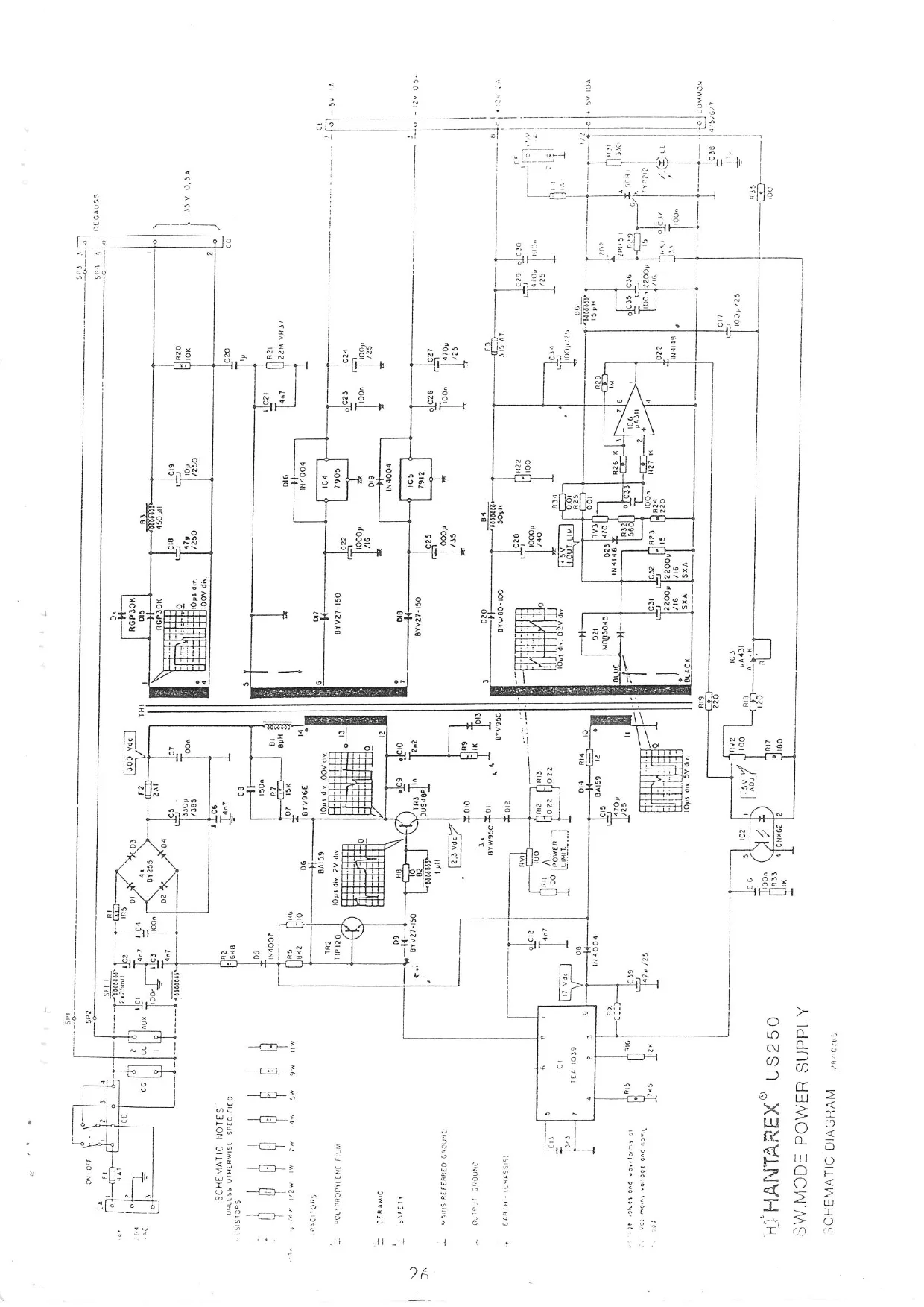
This page is a drawing, shown as the original scan.
foo kt FLECTROCOW ALTOMAT
DI rons , i UNIT6-7-8 rectors: John Stergides - John Collinson
ectais! John Stergides - John SOM Ace Industrial Estate
Ferry Road Cardiff, S. Wales Telephone: 0222-373059 Dear Customer Telex: 892989 ELCOIN Telefax: 0222-394396
Our Ref.
Your Ret:
Date: 21/6/88
AFTER SALES & SERVICE DEPARTMENT — CARDIFF .
We would like to take this opportunity to introduce you to the NEW service department at Electrocoin Automatics — Cardiff.
Normal working hours — 0800 — 16.30 Mondays - Fridays Telephone number 0222 373059 - (This telephone number is now exclusive to Electrocoin After Sales). After Hours /Weekends/Emergencies _ we can now be contacted on the following telephone number — 0836 536195.
For the following enquiries please contact:— Spares Enquiries — Phil Hayes-Pugh or Jan Heppenstall Technical Information — Tan colley
Workshop Manager - Mike Callen Spares & Repairs Aecounts - Julie Tipper
NB. Electrocoin Automatics at Cardiff are responsible for U.K. manufactured machines and all FAMOUS GAMES products. To ensure fast and efficient service prompt return of faulty
parts is essential. Hoping you will avail yourselves of the facilities offered by the After Sales department and assuring you of our continued best attention at all times.