Astro Blaster
Astro Blaster (version 3) (Sega, 1981) · Manual · 65 pages · 35 sections · original scan
& Manual Part No. | 420-0552 =i | iS o S
OWNER’S MANUAL
MANUFACTURED Gremlin/seca’ TLX 910-335-1621
ASTRO BLASTER OWNER’S MANUAL Copyright © 1981 by Gremlin ®/SEGA®, All Rights Reserved
table of contents
Introduction 0.0.0.0. ccc 1 Game Concept ...... 0. 3 Game Set-Up and Inspection ........ 0.0 c cece eeee 5 G-80 Theory of Operation ....... 00. 8 Maintenance Procedures....... 000.0 c ccc cece eens 14 Game Adjustments .......000 00000 c cece eee eee 17 Parts Catalog... 0... cece eee eens 20 Schematics... 00 ec eee e cece neces 48
introduction
Astro Blaster is an electronic. game that makes extensive use of digital integrated circuitry and television monitor concepts. This manual is designed for the maintenance technician who possesses a general knowledge of solid state circuitry, microprocessor and digital integrated circuitry, and TV monitor concepts. Any individual not knowledgeable in these areas should not attempt repair of the electronic portion of the game. Gremlin’s new G-80 system will make troubleshooting easy. Each board has a separate function and most problems can immediately be isolated to a single board. The individual boards contain less circuitry than if they were combined on one or two boards. This results in faster and easier servicing. The new G-80 system gives Gremlin a lot more flexibility in designing new games. Increased ROM capability and the addition of speech means that new Gremlin games will be more exciting and even more profitable. If you have any questions not answered in this manual, call Gremlin/SEGA Customer Service, (714) 277-8700.
This page carries no recoverable text. It is a drawing or a photograph. See the original scan.
9ame concept
Astro Blaster is a one or two player game in which players must advance through squadrons of alien ships in an attempt to dock with the mother ship. Players move their ship left or right and shoot at attacking squadrons. A special time warp allows the player to slow down the alien space ships and their laser fire, while maintaining his own ship and laser fire at normal speed.
Voice Command Astro Blaster is Gremlin/SEGA’s first video game with speech synthesis. As players go through the game play, each step is directed by the voice of mission control. Mission control keeps players informed of fuel status, provides a countdown on warp, keeps track of the number of ships remaining, and monitors the players’ laser temperature.
Game Action As players enter each new sector they encounter a different number of alien squadrons. Players must destroy all ships in each squadron to pass through the sector. One squadron of rockets is extremely difficult to destroy, but players can pass through this squadron by hitting a few enemy ships. Once a player has destroyed all the squadrons in that sector, he enters an asteroid belt. He must maneuver and shoot his way through the asteroids to reach the mother ship. If fuel is critically low when the player enters the asteroid belt, he can receive extra fuel by shooting the red fireballs interspersed among the asteroids. After passing through the asteroid belt, the player’s ship docks with the mother ship and refuels.
Alien Ships
There are 29 different alien squadrons players encounter as they move through the different sectors. Every new sector increases in difficulty with different numbers of squadrons in each sector. Each alien ship has its own individualized sounds, movements and firing capability.
Fuel and Laser Temperature
During their game, players must keep track of fuel consumption. As the player's ship moves through the sector, it consumes fuel. The player must ensure he has enough fuel to advance through the sector and dock with the mother ship. Extra fuel can only be obtained by shooting red fireballs or docking with the mother ship. The screen also displays the laser temperature. As players fire, the laser temperature rises. When they cease firing, it cools down. If the laser overheats, players lose their laser fire until it cools down.
Time Warp
By depressing the warp button, players slow down the enemy ships and their laser fire while maintaining his own at normal speed. Players receive one warp per ship and are awarded one warp upon docking, if he has used his warp in the previous sector.
Scoring
Each alien ship destroyed carries a different point value. Players also receive double points for destroying an alien ship when their fuel is in the red. To add further excitement, there are 25 tasks that a player performs during the course of the game and receives a secret bonus. Players do not know what these tasks are, but a good player will keep track. The 25 tasks are consistent throughout the game. Players also receive a bonus for any fuel they have left when they dock with the mother ship. With a two-player game, players alternate at the conclusion of each sector, not after each ship. Players receive 3 to 5 ships, which is operator adjustable. The game is over when a player runs out of fuel, loses all his ships or crashes while attempting to dock with the mother ship. The top three scores are displayed and the game ranks players from 1 to 99.
game set-up and inspection
Your Astro Blaster game is ready to play immediately upon arrival. But, before you plug in the game, open the rear access panel and make a general inspection of the interior of the game. The following items should be checked to insure no shipping damage has occurred.
- Inspection
- Are the fuses intact? There are five fuses (not counting the monitor fuses which are detailed in the monitor manual accompanying this game). One fuse is located on the AC junction box. The other four are on the power supply PC board.
Hi
- Are the connectors firmly inserted? Proper connector fittings must be checked before game power is applied. Check all related connectors for good contact. Although disconnected connectors are easily spotted, poor contacts are difficult to locate. The connectors should therefore be pushed in firmly and then loosened to spot poor connections. When testing the PC board connectors, always turn off the power.
- Cabinet Inspection Inspect the cabinet interior and exterior to ensure that no damage has occurred during shipping. Check to ensure graphics are in place, monitor is not damaged and that the overall cabinet is in good condition.
- Voltage Selection
Before plugging in your game, make sure that the game voltage is correct for your location. Locate the two leads from the AC junction box to the power transformer. For 100 VAC, they should be connected to terminals 1 and 2 on the power transformer. For 110 VAC, connect 1 and 3, and for 220 VAC applications, they should be connected to 1 and 4.
| 7 | 1 | 7 |
| 2 | 2 | 2 |
| 3 | 3 | 3 |
| 4 | 4 | 4 |
| Yoov | nov | 220 |
You will also notice on the AC junction box that there is a safety interlock switch. When the rear panel is in place the switch is depressed and the game receives power. Removing the rear panel, the switch returns to its original position and the power is cut off from the game. For servicing, this switch can be pulled out and power will be restored.
Safety Interlock Switch
Fuse a
a
- Game Specifications
100 VAC, 60 HZ (nominal), 175 watts 110 VAC, 60 HZ (nominal), 175 watts 220 VAC, 60 HZ (nominal), 175 watts Dimensions 25%2 inches wide X 28 inches depth (64.77 cm wide X 71.12 cm depth) 67 inches height (170.18 cm height) Power
- Important Notes
- The following note is included in compliance with FCC rules:
- Miscellaneous Never remove circuit board connections while power is on. Never replace any components with anything other than exact replacement parts Do Not replace fuses with anything other than the proper value. A blown fuse indicates an overload condition within the game. Replacing the fuse with a higher value can cause severe damage to internal components, if an overload occurs. Correspondence regarding this game should be addressed to: Gremlin/SEGA 8401 Aero Drive San Diego, California 92123 (714) 277-8700
G-80 theory of operation
Game Block Diagram
PROGRAM MEMORY (EPROM) MASTER TIMING
DATA
VIC CHIP:
{2} MONITOR TIMING 'b) ADDRESS MULTIPLEXERS, COMPOSITE SYNC.
ADDRESS.
VIDEO (SCREEN)
ADDRESS: MEMORY
LINES (RAM) 8k x 8
DATA IN MICRO- PROCESSOR 280A READ (IN) DATA OUT
DATA BUS
clock
LOAD S.R. WAITE (OUT)
INPUT PORT
COIN PLAYER
SWITCH CONTROLS “VIDEO SHIFT REGISTER
BIW VIDEO OUT OUTPUT PORT
SOUND BOARD} COLOR GENERATION
RED BLU GRN
COLOR MONITOR SPEECH BOARD}
COMPOSITE SYNC
- DENOTES CIRCUITRY CONTAINED IN VIC CHIP.
- G-80 Boards: The new G-80 system consists of five boards that plug into a mother board.
They are the CPU, Speech, Sound, Video and EPROM boards. They plug into the mother board in a card cage system to simplify repairs and cut down on interference to outside communications systems. The mother board is cross-wired to allow for the boards to be plugged-in in any order. Listed below are the bus pin assignments on the mother board:
| 1 | Ground | A | Ground |
| 2 | A15 | B | A7 |
| 3 | Al4 | Cc | A6 |
| 4 | Al3 | D | AS |
| 5 | Al2 | E | A4 |
| 6 | All | F | A3 |
| 7 | Al0 | H | A2 |
| 8 | AQ | J | Al |
| 9 | A8& | K | AO |
| 10 | D7 | L | D3 |
| 11 | D6 | M | D2 |
| 12 | Ds | N | D1 |
| 13 | «~D4 | P | Do |
| 14. | ~WAIT | R | RESET |
15 INT Ss EDGINT
| 16 | NMI | T | EXT | |
| 17. | ~EXT | SEL | U | OUT |
18 MEMR Vv MEMW
| 19 | INPUT | W = OUTPUT | |
| 20 | RFSH | xX | MREQ |
| 21 | INTACK | Y | AC |
| 22 | +5V | Zz | +5V |
| 23 | +5V | a | +5V |
| 24 | —5V | b | —5V |
| 25 | +12V | Cc | +12V |
| 26 | —12V | d | —12V |
27 e
| 28 | HALT | f | MI |
| 29 | /2 | h | * |
| 30 | * | j | * |
| 31 | SRC | k | * |
32 1 33 m 34 n 35 Pp 36 r 37 s 38 t 39 u 40 v 41 w 42 x 43 y
| 44 | Ground | Zz | Ground |
- For Development Purposes Only
- CPU BOARD (Refer to CPU Schematic, sheets 6 and 7)
The CPU board is completely timed with the video board. But, for testing purposes it contains its own clock circuit, powered by an 8.000 MHZ crystal. Pin 17 is the external clock select and is grounded when the video board is plugged-in. When the external clock pulse comes in through pin T, it goes directly to the CPU and the entire CPU clock circuit is disabled. The WAIT signal, entering in at pin 14, is used to synchronize slower memory accessed by the CPU. The NMI circuit, entering in at pin 16, contains a switch for activating the built-in self-test. The self-test system will be explained more fully later.
When the edge interrupt circuit, entering at pin S, goes LO, it triggers an interrupt in the CPU. The CPU stops whatever it is working on, completes the activity required by the interrupt, and then returns to the function it was performing prior to the interrupt. It is a negatively triggered interrupt, which can be disabled by the CPU at any time.
The AC signal, entering in at pin Y, combines with RESET at pin R and the input from the reset switch located on the operator panel to reset the CPU. Disregard PANEL RESET at pin 30. This circuit is used only for system development.
The CPU in Astro Blaster is a Z80A. You must always use a Z80A as the Z80 is not fast enough to run the game. U21 is an address bus controller. Eight of the sixteen address lines pass through U21 before addressing the RAMs and the Eprom at U25. U25 contains the data for the self-test and contains features common to all games, such as coin acceptance, credit/coin handling, power-up sequence, player 1 or 2 recognition and CPU initialization. U3 is an output port for the CPU and U4 is the input port. Connector P1, pins 23 through 40, shown on sheet 6 is not used in Astro Blaster. U15, located below U4 on the schematic, decodes memory select on the CPU board. Sheet 7 contains the coin inputs, player inputs and inputs from the operator panel. The coin circuitry contains ICs U6, U39 and U16. U9 is the input port for the coin switches and service switch. Player inputs enter through connector P1, pins 15 through 22.
- VIDEO BOARD The video board contains a VIC chip used in previous games (U58). The video board also contains a 15.468 MHZ crystal that generates the timing signals for video generation. Because the video board contains twice as many video RAMs, it has a more extensive graphics capability. Color capability is greatly expanded because of a color RAM, U9, which allows the program to create a wider variety of color schemes. There are 8 shades of red, 8 shades of green, and 4 shades of blue. The video board also contains circuitry (U34, U35, U36, U38, U49 and US50) to make the picture ‘flip’ for cocktail table models. The jumper platform at U12 must be installed for the video board to function properly. DO NOT TAMPER WITH THESE JUMPERS.
- EPROM BOARD
The EPROM board is a relatively simple
memory system. It has 23 2716 EPROMs totalling 46K bytes of memory (1 byte equals 8 bits). U24 and U30 decode all the EPROMs; U25 is the buffer IC to the data bus. In operation, any one of 23 EPROMs is selected by 5 CPU address lines.
- SPEECH SYNTHESIS BOARD The Speech Synthesis board contains a single-chip microcomputer (SCM), U14, an 8035. The SCM has all the basic elements of a computer, except for power, integrated in a single package. There are two main sections to the Speech Board. Section 1, schematic sheet 5, is the speech generation circuit. U7 is the system EPROM and contains all the basic programming for the 8035 CPU. The other EPROMS, U3 through U6, contain the speech information for Astro Blaster. U2 is the actual speech chip which synthesizes human speech. It operates by receiving the
data that compose speech patterns, combines them and outputs the sounds to amplifier U8 and to U11. Section 2, sheet 6, is mainly development circuitry; but, U21 is used in latching the proper 8-bit word from the CPU to select the different speech messages.
- SOUND BOARD The Astro Blaster G-80 Sound Board contains the circuits needed to generate all game sounds other than the speech. The Sound Board circuits are triggered through latches U32 and U33 which are connected to the data bus. The appropriate 8-bit code on the data bus is latched by U33 or U32 to activate the corresponding sound circuit. All sound board signals are mixed by IC U7 and output at P1-1. This output is again mixed with the speech sounds on the Speech Board through connector pin 1 and finally through U11. The final audio output is brought into the power supply amplifier.
- Power Supply The Game Power Supply (800-0128) incorporates all of the voltages and audio power amplification necessary to power Astro Blaster. In addition to the logic supply voltages available, 100 VAC and 115 VAC isolated supplies are available for the TV monitor and fluorescent lights. Also, multiple primary taps are available for using 100 VAC, 115 VAC, or 230 VAC as the input voltage. This supply was originally designed for use with the Dual Game Board or Dual Game VIC Board. Table 1 lists the ratings of the supply when all outputs are used simultaneously. This also happens to be a standard test load. These are worst case ratings (such as when the PROMS in use draw their maximum rated currents) and therefore are rarely encountered when driving Dual Game Boards.
TABLE 1
| +5V@ | 2A | = | 10W |
| -5V@ | 1A | = | 5W |
| +12V@ | 1.5A | = | 18W |
| -122V@ | 1A | = | 12W |
MONITOR & LIGHT 100 VAC or 115 VAC 75W
TOTAL 120W
The rating of the +5V supply can be safely increased to 3.5 amps if the load currents on the other voltages are reduced. This is necessary to prevent the heat sink and transformer temperatures from increasing to the point where reliability suffers.
- Circuit Description: The +5 volt supply consists mainly of U1 and QS. U1 is a 723 voltage regulator IC, which contains a voltage reference, error amplifier, series pass Darlington transistor pair and a current limit transistor. Potentiometer R5 (+5V ADJ) divides the 7.15V (nominal) reference to 5.0 volts as the input to pin 5, the non-inverting input of the 723’s error amp. Pin 4, the inverting input, senses the output voltage. The internal error amp maintains a voltage at U1 pin 10 which is higher than the 5.0 V output by an amount equal to the two VBE drops of Darlington Q5, which acts as a current amplifier, and the IR drop across R32. A foldback current limiter circuit is composed of R32, R2, R3, Ql and the internal current limit transistor of U1. This circuit allows the regulator to operate normally until the load current increases
to the point where the voltage across R32 reaches the value which starts “turning on” the internal current limit transistor. This internal transistor reduces the output current of the regulator to a fraction of the “knee” current when the output is shorted to ground. This feature greatly reduces the power dissipated in QS when the output is accidentally short circuited. This action occurs so quickly during a short that fuse F1 should not blow. The value of the “knee” current can be increased or decreased by decreasing or increasing R3, respectively. Capacitors C4 and CS frequency compensate the regulator so it won't oscillate, and C1 and C26 perform high frequency bypassing. Q1 is included for temperature compensation. Temperature variations of its emitter-base voltage closely match and cancel the baseemitter voltage of the internal current limit transistor. Therefore, the “knee” current of this regulator of about 6 amps stays quite constant over wide temperature variations. The short circuit current is less tham 100 ma. The +12 volt regulator uses 7.15 volts as a reference. U2 compares this voltage with the voltage at the wiper of R23 (+12V ADJ). Darlington PNP Q6 is the series pass element: Transistor Q2 and current sense resistor R12 form the current limit circuit to protect Q6 from excessive load currents. The trip point is about 3 amps. Resistor R10 shuts the circuit off even harder if the output is short circuited. Resistor R11 and electrolytic C7 form a low pass filter which prevents short current pulses from activating the current limit circuit. The —5V and —12V regulators utilize three terminal ICs, 7905 and 7912, respectively. Capacitors C2, C3, Cll and C14 bypass high frequencies so that U4 and US won't oscillate. The audio power amplifier is composed of op-amp U3 and transistors Q3, Q4, Q7 and Q8. U3 provides most of the voltage gain while the transistors supply most of the current gain. This amplifier differs from previous ones in that the output stage also exhibits a voltage gain of about 2 or so that the output can swing close to both power supply rails. This allows this amplifier to supply 36 watts into 4 ohms and 24 watts into 8 ohms. These values will be less if the +12 volt or —12 volt supplies are loaded significantly and/or the line voltage is less than 115 VAC. The overall voltage gain of the circuit is set by the ratio of R20 and R28. The actual value is:
R200 +1= 47K 41 = 22.4 or 27 db R28 2.2K
Capacitor C13 determines the low frequency roll off (about 7 HZ) and forces the DC gain to be unity. Therefore, the circuit does not amplify DC voltage. The input impedance is 47k ohms and is direct coupled.
- Adjustments:
i, Adjust R5 for 5.0V at the load. This compensates for wiring losses. Adjust R23 for 12.0V at the load. There are no adjustments for the —5V or —12V supplies or for the amplifier. The values should be —5V + 0.2V and —12V + 0.5V. ii. iii.
maintenance procedures
- Self-Test Astro Blaster contains a built-in self-test system, activated by depressing the red self-test switch located on the CPU board. If the cover to the G80 card cage is in place, the switch can be activated by putting a pen or pencil through the hole provided on the cover.
a) CPU Board RAM Test — The first test performed is a CPU Board RAM test, for IC’s U26-U29. It is instantaneous and ends when the screen goes white. If there is a problem in the CPU Board, the test will not continue, and you must use standard troubleshooting techniques to isolate and repair the CPU Board. There is a red LED, called the Halt Light, located directly behind the self-test switch. When a problem in the CPU occurs, it will come on and remain lit.
Video RAM Test — The white screen is the beginning of the Video RAM test. If there is a problem here, the halt light comes on and flashes continuously. The screen displays:
CPU HALT VIDEO MEMORY FAILED
CHIP U19
It tells you exactly which chip is defective. The rest of the test will not continue until the faulty RAM is repaired. If the video RAMs are functioning properly, the screen displays: ©) VIDEO MEMORY TEST PASSED
Input Test — The next sequence tests for errors in the input circuitry. The screen display is on the next page. INT in the upper left corner of the screen tests the interrupt circuits to the CPU. To be working properly, random characters should be displayed very rapidly to the right of INT. This shows the interrupt circuits are functioning properly. If the space to the right of INT remains blank, the CPU is not being interrupted properly. Dip Switch settings are displayed to verify the options selection. IPSTART and 2PSTART will not be displayed on the screen initially. Depress the 1-player and 2-player buttons alternately and they should appear on the screen. If not, then there is a problem in the circuitry associated with the 1 and 2 player buttons. The bottom of the screen displays Player Controls. To be functioning correctly, they should all display OFF, then as each switch is depressed, display ON.
d) INPUT TEST
DIP SWITCHE S 4 3
cc
2PSTART
PLAYER CONTROLS P1 LEFT P1 RIGHT P1 FIRE P1 WARP
Coin Test — This test checks the timing of the coin switch. Refer to illustration below. To activate this test, insert coins into both coin
mechs alternately. Coin mech 1 will mech 2 will be displayed as B. Any
appear on the screen as A and coin
EPROM TEST
letter appearing within the good f) Screen Test — This test is a color area indicates the coin switches are test. A solid black box divided into 4 timed properly. The closer the letter quadrants should appear on the comes to either line, though, the screen. The upper left quarter more out of adjustment the coin displays eight shades of green. The switches are. Adjust a faulty coin upper right displays eight red shades switch by bending the trip wire up and the lower left displays four blue. or down, slightly. To proceed to the The lower right quarter should next test, the 1-player button must remain black. The shades of color be depressed. are displayed as bars in each quarter. One of each shade is OFF or will appear to be black. This test must be terminated by depressing the 1-player button.
- Sound Test — The final phase
e) Eprom Test — This test checks PROMs in the entire system. Note the display above. The part number for each Eprom is displayed and whether that PROM is good or bad. displays each type of sound on the screen accompanied by the actual audio sound. It starts with the display, ALL SOUNDS OFF, and continues through seventeen different sounds. The final sequence is VOICE. The test runs through the entire Astro Blaster vocabulary.
At the conclusion of the sound test, the game returns to the advertising sequence and the test is completed. This is a fast test and will not remain on the screen long if none of the PROMs are bad.
game adjustments
17,
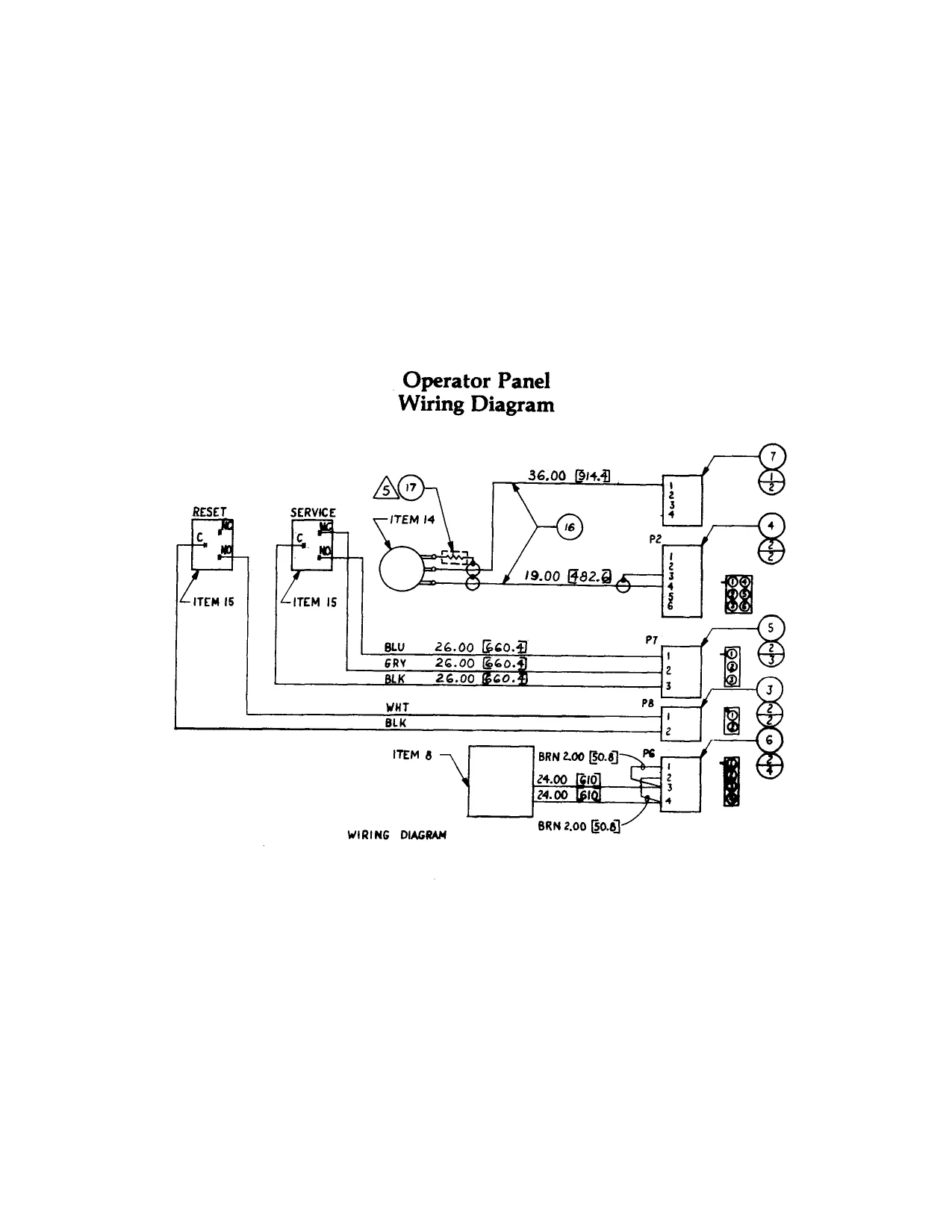
- Operator Panel The operator panel is located on the inside of the coin door behind the coin mechanism. It contains the volume control for adjusting sound, a service switch for giving credits without increasing the coin
counter and a reset switch for resetting the
game.
- Options Selection The following charts define the game and coin/credit options available on the Astro Blaster game. These options are controlled by 2 sets of switches (DIP) located in the upper left hand corner of the G-80 CPU card. Switch #1 is positioned close to the edge of the board; switch #2 is recessed.
ASTRO BLASTER GAME OPTIONS — Switch #1
Game Option Upright - 5 ships Upright - 4 ships Upright - 3 ships Upright - 2 ships
Cocktail - 5 ships Cocktail - 4 ships Cocktail - 3 ships Cocktail - 2 ships NONO NON0e ANDO AnNOON
COIN/CREDIT OPTIONS — Switch #2
Coin/Credit 8 7
4 coin/1 credit
3 coin/1 credit
2 coin/1 credit
1 coin/1 credit
1 coin/2 credit
1 coin/3 credit
1 coin/4 credit
1 coin/5 credit
1 coin/6 credit 9n oo nn OO nN A Cc
fo)
Cc
(o}
Cc
[o}
Cc
Oo
Cc
fe) 2 coin/1 credit 4 coin/2 credit 5 coin/3 credit ANNA OO0Oe% x KKK KKK KO xx KK KKK KE xx KK KK KK x * KK KKK KN x KKK KKK KR
a a > N
0n0o00 00 0D NN A oon Nn Nn HANH NA 0on On On OH OD 77000707070 00 0 & 9 nO 00 000 0 0:0 Oo ON nA AHA An A
COIN/CREDIT OPTIONS — Switch #2
Coin/Credit
2 coin/1 credit 4 coin/3 credit
1 coin/1 credit 2 coin/2 credit 3 coin/3 credit 4 coin/4 credit 5 coin/6 credit
1 coin/1 credit 2 coin/2 credit 3 coin/3 credit 4 coin/5 credit
1 coin/1 credit 2 coin/3 credit
1 coin/2 credit 2 coin/4 credit 3 coin/6 credit 4 coin/8 credit 5 coin/11 credit
1 coin/2 credit 2 coin/4 credit 3 coin/6 credit 4 coin/9 credit
X = Don't Care
parts catalog
- Indicates Recommended Spare Parts — Stock top assembly yu right “Quantity Per Assembly” To Support 5 Games. op ¥ up PARTS LIST DWG NO. 700-0045 Gremlin Qty Per Part # Assembly Description
40 800-0195 41 800-0202 2 800-0204 = ASSY CONTROL PANEL INTERFACE HARN ASSY AC HARN ASSY GND HARN G-80 SCR MACH PHIL 8-32 x2”
| 250-0458 | 1 | SADDLE, G-80 CAGE | |
| 800-0145 | 1 | ASSY J-BOX | |
| 140-0021 | 1 | COVER J-BOX | |
| 140-0049 | 1 | BASIC CABINET WOODGRAIN | |
| 420-0558 | 1 | GRAPHIC INTERIOR | |
| 130-0002 | 1 | SPEAKER COVER 6x9 | |
| 250-0032 | 1 | FRONT BEZEL | |
| 250-0034 | 1 | SPRING RETAINER | |
| 250-0038 | 1 | MOLDING STRIP | |
| 250-0048 | 1 | CLIP SWITCH | |
| 250-0356 | 2 | BRACKET CLR MONITOR SUPPORT | |
| 253-0104 | 1 | PANEL MONITOR | |
| 253-0204 | 1 | PANEL LOGO | |
| 280-0005 | 15 | CABLE TIE | |
| 280-0327 | 15 | BASE TIE WRAP | |
| 390-0019 | 1 | LAMP, FLUORESCENT | |
| 420-0552 | 1 | MANUAL ASTRO BLASTER | |
| 800-0147 | 1 | ASSY FLUOR LAMP 2 | |
| 800-0140 | 1 | ASSY COLOR MONITOR 19” | |
| 420-0028 | 1 | DECAL S/N | |
| 420-0030 | 1 | DECAL CAUTION 115V | |
| 420-0040 | 1 | DECAL RECYCLE | |
| 420-0041 | 1 | DECAL S/N SMALL | |
| 420-0507 | 1 | LIGHT BAFFLE | |
| 420-0526 | 1 | MANUAL ELECTROHOME MONITOR | |
| 800-3139 | 1 | ASSY GAME ELECTRONICS A/B | |
| 800-0176 | 1 | ASSY CONTROL PANEL COMPLETE | |
| 800-0190 | 1 | ASSY XFMR EMI | |
| 320-0020 | 3” | SEALANT FOAM | |
| 31 | 280-0004 | 2 | CLIP WIRE HOLDDOWN |
| 32 | 800-0191 | 1 | ASSY GAME PWR SUPPLY |
| * 33 | 800-0193 | 1 | ASSY COIN DOOR |
| 34 | 800-0194 | 1 | ASSY CASH CONTAINER |
| 35 | 800-0192 | 1 | ASSY SPEAKER HARN |
| 36 | 800-0178 | 1 | ASSY HARN POWER |
| 37 | 800-0196 | 1 | ASSY HARN VIDEO INTERFACE |
| * 38 | 130-0001 | 1 | SPEAKER GAME 6x9 |
| 39 | 800-0197 | 1 | ASSY OPERATOR PANEL |
FRONT VIEW
DETAIL E
Top Assembly Upright
700-0045
SECTION A-A
Top Assembly Upright
700-0045
c
L Oo Oo0 0 ~-----~---+--,
Ht il i
' -O.. 99) i SS
Top Assembly Astro Blaster Upright - Continued
PARTS LIST DWG No. 700-0045
Item Gremlin Qty. Per # Part Assembly | Description
NUT HEX 8-32
420-0568
250-0469 WASHER FLAT #8
PARTS LIST DWG NO. 800-0176 WASHER LOCK SPLIT #8
Gremlin Qty Per Part # Assembly Description WASHER FLAT #10, %” OD BOLT CARRIAGE #10-24 1%” NUT WING #10-24 SCR PHIL PN HD #8X 1%" SHT MTL SCR PHIL PN HD #6 %2” SHT MTL SCR PHIL PN HD #10X ¥2” SHT MTL DECAL FCC SCR PHIL PN HD #10 x %” SHT MTL SCR FL HD #10 %” SHT MTL SADDLE G-80 PWR SUPPLY OR ot oe RO eS
assembly control panel SCR PHIL RD HD 48x %2" SHT MTL BOLT CARRIAGE #10-24 2” NUT HEX #10-24
240-0006 BUTTON PLUNGER RED 240-0008 3 BUTTON PLUNGER WHT 240-0009 2 BUTTON PLUNGER YEL
250-0367 253-0031 253-0205 280-0005 280-0327 280-0329 510-0023 800-3141 SUBPANEL METAL SPACER, WICO SWITCH GRAPHIC CONTROL PANEL CABLE TIE BASE TIE WRAP NUT HEX PAL ¥%-13 ASSY SWITCH WICO ASSY HARN CONTROL PANEL ROAR REE
Assembly Control Panel
800-0176
assembly operator panel
PARTS LIST DWG NO. 800-0197 Gremlin Qty Per Part # Assembly Description
| 1 | 211-0005 | 2 | CONN CRIMP |
| 2 | 211-0042 | 11 | CONN SOCKET AMP |
| 3 | 211-0043 | 1 | CONN PLUG AMP 2 PIN |
| 4 | 211-0045 | 1 | CONN PLUG AMP 6 PIN |
| 5 | 211-0059 | 1 | CONN PLUG AMP 3 PIN |
| 6 | 211-0073 | 1 | CONN PLUG AMP 4 PIN |
| 7 | 212-0005 | 1 | CONN FEM BLK 4 PIN |
| 8 | 220-0008 | 1 | COUNTER DIGITAL |
| 9 | 240-0001 | 1 | KNOB VOL CONTROL |
| 250-0459 | 1 | BRKT OPERATOR CONTROL | |
| 280-0005 | 12 | CABLE TIE | |
| 280-0117 | 1 | TAB RIVET | |
| 420-0561 | 1 | DECAL OPERATOR PANEL | |
| 475-0007 | 1 | POT 10K CAR PNLMT | |
| 510-0051 | 2 | SW PUSHBUTTON SLIDE | |
| 600-0013 | SFT | CA1COND SHLD | |
| 471-0031 | 1 | RES 330 OHM %2W 5% |
SCREW PHIL PAN 6-323/8 MACH WASHER FLAT #6 WASHER LOCK #6 NUT HEX 6-32 RIVET POP AL 1/8
Assembly Operator Panel 800-0197
ddd [y's2] 0071
Assembly Operator Panel
800-0197
assembly coin door
PARTS LIST DWG NO. 800-0193 Gremlin Qty Per Part # Assembly Description 220-0035 LOCK FORT LOCK 220-0160 COIN MECH 250-0470 FRAME COIN DOOR 280-0005 CABLE TIE 280-0327 BASE TIE WRAP 800-0174 ASSY HARN COIN MECH
BOLT CARRAGE 10 - 24x %2BLK WASHER FLAT #10 WASHER LOCK SPLIT #10 NUT HEX 10-24
Assembly Coin Door 800-0193
Assembly Coin Door
800-0193
7 ) Ser NA N74 Wa NI
PARTS LIST assembly sound board
DWG NO. 800-3122
mn Gremlin — Per Part # ssembly | Description Ref Des
170-0210 212-0081 482-0006 482-0023 313-0039 314-0001
314-0018 314-0019 314-0067 314-0042 314-0043 314-0093 315-0006 315-0007 315-0035 315-0052 481-0008 481-0006 150-0087
150-0088
150-0089 151-0001
151-0008 152-0001
152-0005 152-0010 152-0017 152-0039
152-0045 a Rawyeer P.C. BOARD CONN 4 PIN M RTG XSTR 2N4403 XSTR 2N4093 IC TLO84CN IC NESSS
IC 74LS00 IC 74LS04 IC 74LS30 IC 7406 IC 7407 IC 74LS374 IC CD 4017 IC CD 4011A IC MMS5837 IC CD4024 DIODE, ZENER INS231 DIODE IN914/IN4148 CAP E 4.7uf 25V
CAP E 10uf 25V
CAP E 22uf 25V CAP CER .0Suf 50V
CAP CER .001uf 50V CAP FILM .1uf 100V
CAP FILM .0047uf 100V CAP FILM .022 uf 100V CAP FILM .33uf 100V CAP FILM .O1uf 100V
CAP. FILM .0022 100V Pl Q1-3, 7-10 Q4-6 U1, 2, 7, 16, 22 U4-6, 13, 17, 18, 20, 23, 24, 37, 38 U34 U36 U35 U30, 31 U26, 29 U32, 33 U3, 15 U9-11, 21, 25, 27 U8 U12, 14, 19, 28 D1, 3-6, 10 D2, 7-9, 11-31 C47, 58, 60, 61, 69,
C6, 12, 15, 27, 33, 34, 43, 46, 56, 62 C48 C4, 10, 11, 13, 14, 19, 28-30, 32, C49-52, 54, 55, 66, 67, 72-75, C79, 81 C42, 44, 45 C3, 5, 7-9, 20, 39, 35, 37, 38, 53, C57, 63, 64, 70, 78, 82 C31, 68, 77 C18, 26, 71, 76 C21, 22, 59 Cl, 2, 16, 17, 24, 25, 23, 40, 41, 65 C36
Assembly Sound Board
800-3122
Assembly Sound Board - Continued
PARTS LIST DWG No. 800-3122 Gremlin pe Per Part # ssembly | Description Ref Des
471-0104 RES 100K OHM %2W 5% | R1, 10, 21, 23, 36, 42, 45, 59, 61, R62, 70, 73, 75, 82, 90, 91, 107, 108, R115, 124, 133, 146, 148, 149, R169, 171, 88 R20, 44, 80, 100, 101, 103, 142, R151, 165, 166, 168, 185, 98, 99 471-0105 RES 1M OHM %2W 5%
471-0124 RES 120K OHM %2W 5% | R161
| 471-0152 | RES 1.5K OHM ”W 5% | R2, 37, 63, 92 |
471-0154 RES 150K OHM %2W 5% | R11, 79, 85
| 471-0183 | RES 18K OHM ”%W 5% | R8 |
RES 22K OHM %2W 5% R7, 28, 32, 50, 54, 76, 128, 130, R135, 141, 144, 178, 152,
R15, 120 R24, 55, 138, 147, 471-0223
RES 220K OHM ¥%2W 5% RES 2.2 M OHM ”%W 5% 471-0224 471-0225
| 471-0243 | RES 24K OHM “%2W 5% | R154 |
| 471-0273 | RES 27K OHM %2W 5% | R157 |
471-0275 RES 2.7M OHM %2W 5% | R18, 106, 134
| 471-0333 | RES 33K OHM 2W 5% | R9, 56, 57, 150, |
158, 172 RES 330K OHM “%W 5% | R3, 13, 38, 64, 77,
R33, 49, 126 131, 156, 12 R34, 35, 74, 97, 122, 137, 140, 145, R162, 184, 139 471-0334
471-0393 RES 39K OHM ”2W 5%
471-0472 RES 4.7K OHM %2W 5%
| 471-0473 | RES 47K OHM 2W 5% | R14, 27, 153, |
173-177, 179-181 471-0474 RES 470K OHM %2W 5% | R22, 43, 46, 69, 102, 116, 118, 119 R155 R159 RS, 6, 40, 52, 66, 95 R30, 48, 68, 125, 132, 160 RES 56K OHM ”%W 5% RES 62K OHM %2W 5% RES 68K OHM %2W 5% RES 82K OHM ”%2W 5% 471-0563 471-0623 471-0683 471-0823
Assembly Sound Board - Continued
PARTS LIST DWG No. 800-3122 Item Gremlin Qty. Per
| # | Part # | Assembly | Description | Ref Des |
| 52 | 471-0824 | RES 820K OHM “%W 5% | R26, 58 |
| 53 | 471-0562 | RES 5.6K OHM %2W 5% | R84 |
| 54 | 471-0102 | RES 1K OHM %W 5% | R19, 78, 83, 117, |
123, 136, 167, 186 RES 10K OHM %W 5% R4, 16, 17, 25, 29, 31, 39, 41, 47, RS1, 53, 60, 65, 67, 71, 72, 81, R86, 87, 89, 94, 96, 104, 105, R109-113, 121, 127, 129, 163, R164, 182,
RES 100 OHM %2W 5% R114 CARD EJECTOR 55 471-0103
471-0101 280-0330
PARTS LIST
150-0088 151-0005 151-0012 151-0020 151-0060
6 151-0061 7 170-0194 8 211-0008 9 212-0098 230-0013 314-0001 314-0015 314-0018 314-0019 314-0055 314-0058 314-0062
314-0066 314-0067 314-0068 314-0078 314-0083 314-0085 314-0087 314-0093 314-0099 314-0105 315-0041 315-0046 315-0050 316-0764 390-0003 471-0101 471-0102 471-0103 471-0104 471-0122 471-0220 471-0221 assembly cpu board
DWG NO. 800-0107
Description
CAP E 10 uf 25V CAP CER 680pf 50V CAP CER .1uf 50V CAP CER 33pf 50V CAP CER .1uf 16V AX
PC BOARD CONN PIN TEST PT CONN M 10 PIN RTA XTAL 8.000 MHZ IC NESSS IC 7404 IC 74LS00 IC 74LS04 IC 7418244 IC 74LS08 IC 74LS74 Ce a a 4
IC 74LS27 IC 74LS30 IC 74LS32 IC 74LS02 IC 74LS240 IC 74LS14 IC 74LS139 IC 74LS374 IC 74LS245 IC 74LS253 IC Z80A IC 2114 IC 2516 (2716 IC PROM 32X38 LED RED RES 100 OHM %2W 5% RES 1K OHM %2W 5%
RES 22 OHM %2W 5% RES 220 OHM %2W 5% WRRPNNNE PPP RP RE ERNE ENR CAP CER 220pf 16V AX
RES 10K OHM ¥%2W 5% RES 100K OHM %2W 5% RES 1.2K OHM “W 5% C43, C45, C45, C62 C50 C47 ca49 C37-C42, C44, C48, CS51-C61 C1-C36
TP1-TP4
Y1 U12 U30 U6, U8, U14, U19 U18 U34, U36, U38 U13 U10, U11, U17, U20, U39 Ul6 U37 U32, U33 U23 U4 U7, U31 U24 U3 U35 U1, U2, US, U9 U22 U26-U29 U25 U15 D3 RS R1, R3 R6, RO *R7, R8 R12 R14 R2, R4, R13
_J L__ NO Og ©
oa ho’ beBeg oad 1s 7
HE HHH S97 He i=) Oo hh ae be A oe “VS oe?
n sit aha fe | oot _ a a BOG GREGROG ANGHIAN EH MUEE REG) GAdG gahR i, f
Assembly CPU Board
800-0107 “ a gag fe C)
a a +
Assembly CPU Board - Continued
PARTS LIST DWG No. 800-0107 Qty. Per Assembly
| 471-0331 | RES 330 OHM %W 5% | R10, R11, R15-20 | |
| 477-0002 | 3 | RES PACK 15 X2.2K | RP1-RP3 |
| 481-0001 | DIODE IN4002 | Di, D2 | |
| 481-0006 | DIODE IN914/IN4148 | D4 | |
| 482-0006 | XSTR 2N4403 | Q7 | |
| 482-0010 | XSTR PE8050 | QI, Q2 | |
| 482-0014 | XSTR 2N4401 | Q3-Q6, Q8 | |
| 510-0052 | SWITCH PIANO DIP. | SW1 |
510-0053 SW PUSHBUTTON SIDE PCM sw3 SKT 24 PIN DUAL INLN |} XU25 SKT 18 PIN DUAL INLN | XU26-XU29 SKT 16 PIN DUAL INLN } XU15 SKT 40 PIN DUAL INLN | XU21, XU22 SWITCH 8 POS DIP sw2 RES 4.7K OHM “%W 5% | R21 CARD EJECTOR fo
RPRUNHEHEN
213-0001 213-0002 213-0004 213-0005 510-0049 471-0472 280-0330 NERPNHR AY
assembly speech synthesis
PARTS LIST
Gremlin Part # Qty Per Assembly Description
150-0087 150-0088 151-0021 151-0056 151-0058
151-0060 170-0223 212-0012 230-0033 280-0330 313-0037 313-0038 314-0058 314-0062 314-0067 314-0072 314-0085 314-0087 314-0100 314-0042 314-0131 315-0061 315-0077 315-0079 316-0788
471-0103 471-0106
471-0222 471-0223 471-0254 471-0471 477-0002 471-0683 475-0022 151-0009 471-0472 213-0001 213-0004 OrRNaAH
PREP BPR BPP RRR PREP ENP PR
Ra
PUPP RRP ENE AR CAP E 4.7 uf 25V CAP E 10 uf 25V CAP CER 20pf 50V CAP CER .047uf 50V CAP CER .Oluf 16V AX
CAP CER .1 uf 16V AX PC BOARD CONN 6 PIN M CRYSTAL 3.12 MHZ CARD EJECTOR IC TL081 CP IC TLO82 CP IC 74LS08 IC 74LS74 IC 74LS30 IC 74LS174 IC 74LS14 IC 74LS139 IC 74LS273 IC 7406 IC 74LS373 IC ST-32034 IC 8035 IC CD 4053 IC PROM SPEECH BD. DECODER RES 10K OHM ”W 5% RES 10 MEG OHM ¥%2W 5% RES 2.2K OHM ”%W 5% RES 22K OHM ”%W 5% RES 250K OHM %2W 5% RES 470 OHM %2W 5% RES PACK 15 X2.2K RES 68K OHM %2W 5% POT 100K 10T PCMNT CAP CER .003uf 100V RES 4.7K OHM ¥%2W 5% SKT 24 PIN DUAL INLN SKT 16 PIN DUAL INLN DWG NO. 800-0183
C2 C13, C46-C49 C6, C7 C10 C5, 11, 12, 14-17, 19, 20 C9, C37, C38
Y1
us Ul1 U35 U15 U37 U20 U38 U10 U21 U13
R17, R21, R27-R29
“OQ on nO “OQ O
Assembly Speech Synthesis
800-0183
Assembly Synthesis - Continued
PARTS LIST DWG No. 800-0183
—_ Qty. Per Assembly | Description Ref Des
SKT 40 PIN DUAL INLN SKT 20 PIN DUAL INLN SKT 8 PIN DUAL INLN SKT 28 PIN DUAL INLN xXU2 1C 2716
assembly G-80 2716 eprom board
PARTS LIST DWG NO. 800-0151 Gremlin Qty Per Part # Assembly | Deéscription Ref Des
151-0058 CAP CER .0luf 16V AX | C2, C4, C6, C8, C9, C11, C14, C16, C18, C21, C23, C25, C27 151-0060 CAP CER .1uf 16V AX C1, C3, C5, C7, C10, C12, C13, C15, C17, C19, C20, C22, C24, C26, C28 P C BOARD SKT 24 PIN DUAL INLN | XUI-XU23 IC 74LS244 IC 74LS08 IC 74LS10 IC 74LS138 IC 74LS154 CONN PIN TEST PT CAPE 10uf 25V CARD EJECTOR 170-0211 213-0001 314-0055 314-0058 314-0059 314-0104 314-0120 211-0008 150-0088 280-0330 *
an ° NeEwRRRwEPE
| ‘acd JOOL DUOC N00 JAKE ASL rm fs BeBe Uh @
- ss
Assembly G-80 2716 EPROM Board
800-0151
PARTS LIST assembly video I board
DWG No. 800-0106
Qty Per Assembly | Description Ref Des
151-0005 151-0008 151-0011 151-0058
151-0060
151-0061 152-0007 170-0193 211-0008 230-0009 212-0099 314-0001 314-0040 314-0046 314-0058 314-0059 314-0062 314-0067 314-0068 314-0070 314-0073
314-0076 314-0077 314-0085 314-0086 314-0087 315-0039 315-0042 315-0065 314-0093 314-0101 314-0104 314-0123 314-0124 314-0125 316-0806 OQPRRE RN ENHENNEHWENE
PENNER HERE R RP N EN CAPE 10uf 25V CAP CER 680 pf 50V CAP CER .001 uf SOV CAP CER .01 uf 50V CAP CER .01 uf 16V AX
CAP CER .1 uf 16V AX
CAP CER 220 pf 16V AX CAP FILM .001 250V PC BOARD CONN PIN TEST PT XTAL 15.46848 CONN 15 PIN M RTA IC NESS5 IC 74LS125 IC 74LS04 IC 74LS08 IC 74LS10 IC 74LS74 IC 74LS30 IC 74LS32 IC 74LS86 IC 74LS175
IC 74LS157 IC 74LS166 IC 74LS14 IC 74LS163 IC 74LS139 IC 4015 IC CUSTOM CHIP IC 93419 IC 74LS374 IC 74LS283 IC 74LS138 IC 74LS257 IC 74LS33 IC 74LS38 IC 32X8 PROM C57, 60, 63, 70, 71, 84,
13-53, 56, 58, 59, 62, 66-69, 72-78, 83, 85, 86, 88, 89 c1-c12 C55, C61
U3, U4, U39, U40 U42, U43, U49, US4, USS US6, US7 U33-U36 U37, U47 U53 U1s U16-U31 USs8 u9 Ul11 U38 US1 U13, U14 U7, U8 U46 US2
Assembly Video I Board - Continued
PARTS LIST DWG No. 800-0106
- Per ssembly Description
| 471-0102 | RES 1K OHM “%W 5% | R4-R6, R15, R16 |
471-0103 RES 10K OHM %2W 5% 471-0122 RES 1.2K OHM %W 5% 471-0202 RES 2K OHM “%W 5% 471-0222 RES 2.2K OHM “%W 5% 471-0242 RES 2.4K OHM ”2W 5% 471-0330 471-0331 471-0472 RES 33 OHM “%W 5% RES 330 OHM %2W 5% RES 4.7K OHM %W 5% 471-0563 RES 56K OHM "%W 5% 481-0006 DIODE IN914/IN 4148 482-0006 XSTR 2N 4403
| 482-0014 | XSTR 2N 4401 | Ql |
213-0004 SKT 16 PIN DUAL INLN | XU16-XU31, XU52 213-0005 SKT 40 PIN DUAL INLN | XU58 213-0012 SKT 28 PIN DUAL INLN | XU9, XU12
| 315-0067 | HEADER 28 PIN | U12 |
| 477-0002 | RES PACK 15.X2.2K | RP1 |
471-0221 280-0330 RES 220 OHM %2W 5% CARD EJECTOR R1-R3 NORPENHEQRPERENNNNWENNY
assembly G-80 cage
assy. G-80 cage bracket, G-80 cage assy. 6 slot master board assy., fan G-80
CT Lo oOo FF egal = - WRG RGU Beeat affotl CIE Le IEEE DARE aa cc df V4 a Ta = icathicant = & ic ye CALE Ely
Assembly Video I Board
800-0106
PARTS LIST P.C. assembly game power supply
+ OONAKNRWNE ay °o Gremlin Part #
150-0088 150-0092 150-0095 150-0096 150-0097 151-0001 151-0002 151-0007 151-0008 151-0011 151-0012 170-0202 180-0008 313-0001 313-0004 313-0015 313-0023 471-0011 471-0101 471-0102 471-0103 471-0122 471-0221 471-0222 471-0272 471-0332 471-0471 471-0472 471-0473 473-00R1 473-00R2 475-0004 481-0004 481-0008 481-0006 482-0006 482-0014 482-0019 482-0100 514-0002 Description DWG NO. 800-0128
Ref Des
CAPE 10 uf 25V RDL CAPE 100 uf 25V RDL CAPE 3300 uf 16V RDL CAPE 6800 uf 16V RDL CAPE 4700 uf 25V RDL CAP CER .05 uf 50V CAP CER 100 pf S0V CAP CER .005 uf 100V CAP CER .001 uf 50V CAP CER .01 uf 50V CAP CER .1 uf 50V PC Board CHOKE 1uH IC LM 723 DIP IC LM 741 EN DIP IC LM 320T-12 IC LM 320T-5 RES 10 OHM “%W 5% RES 100 OHM %2W 5% RES 1K OHM “%W 5% RES 10K OHM “%W 5% RES 1.2K OHM %W 5% RES 220 OHM %2W 5% RES 2.2K OHM %2W 5% RES 2.7K OHM %2W 5% RES 3.3K OHM “%2W 5% RES 470 OHM %2W 5% RES 4.7K OHM %W 5% RES 47K OHM “W 5% RES .1 OHM 5W 3% RES .2 OHM 3W 5% POT 1K CAR PCMTV DIODE MRs01 DIODE INS231 DIODE IN914/IN4148 XSTR 2N4403 XSTR 2N4401 XSTR TIP 120 XSTR TIP 125 FUSE 3A NORM C2, C3, C7, C11, C13, C14 C8, C9, C15, C26 C24 C25 C22, C23 C1, C6, C20, C21 C10, C16, C17 cs C12, C18 C4 c19
R6, R7, R11, R15, R16, R21, R22 R8, R19 R3 R17, R18, R24, R25
PC Assembly Game Power Supply — Continued
PARTS LIST
CLIP FUSE MTG FUSE 1.5A NORM CONN 4 PIN M CONN 10 PIN M
PC Assembly Game Power Supply
800-0128
OMBNAURWNE
=)~]e]sl/ele| le] 2 BRN PARTS LIST
Gremlin Part #
211-0005 211-0017 211-0042 211-0059 212-0016 250-0433 250-0434 280-0005 280-0014 280-0117 560-0054 800-0128 AryHEARAORHEHHP ORR RPP RORY DWG NO. 800-0146
rid Per ssembly Description
BRN /YEL BRN
RED/YEL. Bik 100.00 [4.00] <f RED assembly linear power supply
CONN CRIMP LOCK CONN FEM QUICK’ CONN SOCKET AMP CONN PLUG 3 PIN AMP CONN FEM 10 PIN HEAT SINK PWR SPLY ISOL CHASSIS PWR SPLY ISOL CABLE TIE STAND OFF CLIPS TAB, RIVET XFMR ISOL P.C. ASSY GM PWR SPLY RIVET POP 3/16 SCR MACH PN HD #4-40x™% SCR SHT METAL 46x % WASHER FLAT#10 TRANSISTOR INSULATOR CONN PLUG 2 PIN AMP ELECTRIC TAP SPLICE 2 COND ZIP CORD
ITEM HI
BLK BLK / WHT (wer ‘\@ ZR
RED
~——____———. 76.00 [7.00} ————————_ 228.00 [12.06] ————___—_=|
Assembly Linear Power Supply 800-0146
ITEM 18
ITEM 4
This page carries no recoverable text. It is a drawing or a photograph. See the original scan.
This page is a drawing, shown as the original scan.
This page is a drawing, shown as the original scan.
G-80 SPEECH /SYN BOARD 800-3144 GAME ELECTRONICS 800 ~ 3139
OTHER BO
6-80 CPU BOARD 800-3143
WBNS BRA KIT IBW Wi og —Nw se ved
6-80 VWED BOARD B00 -vIDe | czewseasus7se 1a] oe ne) wean 44532167890) aoe eu ene TO OS
) ag P/O 800-0197
isw@4eezau7!1a2560 ee4Bausi7vigz25 60
jnsno-3e1 C
; x LEFT RIGHT | WARP FIRE IPLYR ZPLYR CONTROL PANEL 800 - 0176
WIRING + DIAGRAM NOMENCLATURE. OR DESCRIPTION PARTS LIST
Top Assembly Astro Blaster Upright
- ——a Prgh
NEXT ASS USED_ON [APPLICATION D0 NOT SCALE DRAWING: [sHeer 7_oF 7
This page reads as a drawing: its text was drawn rather than typeset, and comes out in fragments. See the original scan.
u7 Jad o!2_3e2_ xINT (SHT 6) A] RELEASED way or BL ECN #528
ss INTCL (SHT 6) .
@3 ai 2N4401 Peaoso J,
v2 =, 1N4002
C26 RST RST HF y GATE)
OUT 37! Td [5 bola [> C25 (SHT 6) c24
+5 RP3 15% 22000. At &(SHT 6) z Ag i D5 (SHT 6) [|
D4 (SHT 6)
220 ra 2 Pts PF cia
03 (SHT 6)
D2 (SHT 6)
}2—— 1 (SHT 6)
Da (SHT 6)
C77 |. 022af x7 004 Ta FILM FILM
(ges LONG
SHE EXPL
pie (U30-3}) {f-sasea ond ire) O5uf RI 10K
ATTACK: (W262 SHT8)
[/--LaseR-2 6m) ae
PORT O76
}—PORT O77
U3) 2 Po See lok a ies U3!
7 eas (SHT 7} MUTE HT ® bape ) = Bpot ware (S477) i +-22ipot AFIT Gur) LIZA 0 REFILL @HT7)
#1
IWWADER ~ 4 eH) SHT 7}
C14, 30,66,79 M3aF 6 ~\avpc
1, ALL OP-AMPS ARE TLO84CNS-
- ALL DIODES ARE-IN94/IN414B8 EXCEPT AS NOTED.
- ALL RESISTORS ARE VEW 5% UNLESS OTHER WISE SPECIFIED.
- See pane
RE SCRE LST — Yo Buea Mee wens Fovekanets Ane FAcTONS OCOMALS ANGLES : ae
This page reads as a drawing: its text was drawn rather than typeset, and comes out in fragments. See the original scan.
(sHT 6) (sHT 6) (07 D605 D4 D3 D2 OF DB) (AB az Al AG CS C4 V2 VI) E [SEE SH S FOR REVISIONS
use
AG Lss2 x
| * | 7 | 3 |
| 1 | j27__ | 2 |
| ag | AZ | AT |
NOSFT HT 6) c) 76 OUT vu
[9 out277
RW2 (sHT 6) YI 15.468 MHz __ ag D (suT6) Ls74 u6 15}
| & | cy | Ree | WOT | Res |
ua7 va7 3300 3300 1132 99 Ls 14 | 1 veo | Sea
| I RST (SHT 6) | ALP | FLIe | tafe | ts |
(sHt 6) (SHte) +5 1g 74804 +5 R23 | Y6o' 19, t S86 7438 [2.2K
- }V40) 23 iL 12/046) RAMW (SHT 6) COMPSYNC
COMP VID
YEN (SHT 6)
L.Ri (SHT 6)
MEMR (SHT 6)
RWe (SHT 6)
je *pe— RWi (sHT 6) VAWT (sHT ©) too 12] D al
MYWT (SHT6)
Pp
as -C53, C56yCSBy C594 €62,C66-CES, C72-C7B 65,06 T CBuyCBB;CRS eRe SRL sRL We WT WAS VRAS) -1UF (sHT 6) C57, C60, C63, C70, €71,C84,C87 c22-c29 C46-CS3 -O1UF
‘SCALE DRAWING
A BER SCN 676 C} PER ECN 593
INSTALL JUMPERS PROG DATA
| 216 | A, | E;G/1/K /M,"ko* |
| 2732 | Bc | FyG/T/K/M 5 "32" |
| TMS 2532 | A,D | E;H/T/L/N 5 "32" |
600-0/63 |C
"APPLICATION. ‘DO_NOT SCALE DRAWING.
aE avo» (sue) [_|A| RELEASED crc | a) to | Za | R22 a a 4 PER EcN 5% 22K Ary re) CC} PER ECN 593 v R23 32 4.70F MONO 3K ouT
CS4,,.002UF
Rt 2 ser cs ow [> =O) TL0s2 4-70F cert 8B ouT
uF
c4 yt +
TL082 4.70F RIGHT 4 4 5 ouT
£23) VoTRAX
1s
2.2UF
R6O 47K
800-0183 {C
C5, Cla, C16 ,620,
CB, CI4, C5,
74.508 [s[vz7)
T4LS08 f {uz
12744508 fisfued
74LSOB fiofver)#
4741508 [sluze*
1 741508 f2|vee)
12 7TALSOB [isfuze)!
9 741508 fiofves)
Teo 0-287
‘BUFFER C1,C3,C5,C7, €10,¢12,c13, Cis. ci7,C19, C28C24 C2 6. Ot uf €25,C27,
Olaf 210-217 220-227 230-237 240-247 250-257 ‘260-267 210-277
sal hel YY YY Y Yel doggone DB D1 Dz D3 D4 DS DE D7 B00-O18\
[ [A | RELEASED ete 7LVH pease a? |e [Per ECN © 554 wal 2-09-80 | 3
[_TETPER ECN G3! widfi-ze-si| | | | zone [tre]
c
MRSO! (4) cima oe . aia V [05 wt D7 + 8 7 esovac Bo nisvacy) sor f NB VAG 100 ACF monrTOR| y" 100 VAC NO ovac ovac revenge £ CZ =, a 7 c2i of OR AUDIO IN
us L_] 320T-12
|, ALL RESISTANCE VALUES ARE IN OHMS, /2W, 257. NOTES! UNLESS OTHERWISE INDICATED
This page carries no recoverable text. It is a drawing or a photograph. See the original scan.