Football TM-126 3rd Printing
Football (Taito do Brasil, 1981) · Technical Manual · 116 pages · 54 sections · original scan
Boyeyeo syed payesisn}|| uM ajajdwog Jenuey] sdlAsag pue soueusjulep| ‘uol}esedO TIVELY
GAME SERIAL NUMBER LOCATION
Your game’s serial number is stamped on the circuit (back) side, bottom right corner, of the printed circuit board—see the illustration below. The same number is also stamped on the TV monitor chassis and on the label located on the rear of the game cabinet. Please mention this number whenever calling your distributor for service.
FOOTBALL Operation, Maintenance and Service Manual
Complete with Illustrated Parts Catalog
ATARI INC. 1265 BORREGAS AVENUE PO. BOX 9027 SUNNYVALE, CALIFORNIA 94086 408:7 45-2000 + TELEX 35-7488
A
ATARI
‘A Warner Communications Company tw)
Copyright © 1978 by Atari, Inc. All rights reserved
No part of this publication may be reproduced by mechanical, photographic, or electronic process, or in the form of a phonographic recording, nor may it be stored in a retrieval system, transmitted, or otherwise copied for public or private use, without permission from the publisher.
For permission requests, write:
ATARI INC 1265 Borregas Avenue P.O. Box 9027 Sunnyvale, California 94086
1H
Lithographed in the U.S.A.
TABLE OF CONTENTS
1 LOCATION SETUP A. INTRODUCTION. . B. GAME INSPECTION . eeges Cc. INSTALLATION REQUIREMENTS Line Voltage Selection ... Type of Power Cord . Pee eee eee ee D. INTERLOCK, POWER ON/OFF SWITCH AND OTHER RELATED OPERATOR CONTROLS Interlock Switch Checkout Procedure . . OPERATOR OPTIONS .............. saree ee eee SELF-TEST PROCEDURE............ feuds 22 Get VOLUME CONTROL ...... omm
2 GAME PLAY A. INTRODUCTION ....... B. PLAYER CONTROL PANEL . The Play Select Board ..... ATTRACT MODE........ READY TOPLAY MODE.... PLAY MODE . a PHYS... oe ee cee eee Offensive Running Plays . The Sweep Play . The Keeper Play... : Offensive Passing Plays The Bomb Play .. : The Down and Out Play .. . Defensive Running Plays . The Sweep Play The Keeper Play... Defensive Passing Plays The Bomb Play . . The Down and Out Play The Four Goal Deterrents Time Penalty ............-- The Touchdown : The Downs ...........-. moo
GENERAL INFORMATION POWER SUPPLY .............. 3 THEORY OF OPERATION A B. Cc. MICROPROCESSOR CIRCUITRY . dqtthdgeeyye es oot = cue = MPU, ROMandRAM ...............- eee eee . Address Decoding .. 00.0660 0 cece eee
iii
TABLE OF CONTENTS
0 Clock Driver . Watchdog Reset ........... SYNC GENERATOR ...... ALPHANUMERIC GENERATOR SCROLLFIELD GENERATOR . MOTION OBJECT GENERATOR . er TOMS TRACKBALL CONTROL AND cere INPUT CIRCUITRY . tee : ; : ; “318 VIDEO OUTPUT...... 00.0
MAINTENANCE AND ) ADJUSTMENT CLEANING «1.00. eee COIN MECHANISM . Components on Coin Door. Access to Coin Mechanisms . Cleaning of Coin Paths Lubrication.............. Adjustment of Coin Switch Trip Wire a Mechanical Adjustments on Coin Mechanism . General Troubleshooting Hint........... TV MONITOR ADJUSTMENTS FUSE REPLACEMENT .......... eiees weaeee TV MONITOR REMOVAL ...........0 000 -000005 CONTROL PANEL REMOVAL ....... TRACKBALL ASSEMBLY REMOVAL..... PLAY SELECT BOARD ASSEMBLY REMOVAL . fae LED (LICON) PLAY SELECT/PASS SWITCH REMOVAL . eee BASE ASSEMBLY REMOVAL ............0.. 000000005 been ee 4-10 om zommoo
5 ILLUSTRATED PARTS CATALOG
LIST OF ILLUSTRATIONS
Figure 1-1 Figure 1-2 Figure 1-3 Figure 1-4 Figure 1-5 Figure 1-6 Figure 1-7 Figure 1-8 Figure 2-1 Figure 2-2 Figure 2-3 Figure 2-4 Figure 2-5 Football Control Panel ......... 1-2 Football Cabinet Assembly .. . . 13 AC Line Voltage Check .... 1-4 Voltage-Selection Connectors . 1-5 Location Set-Up Requirements . es, erewasicaan. 126 Location of Interlock and Power On/Off Switches . eee eee 1-6 Option DIP Switches and Game PCB Location and Removal . _ 1-7 Location of Switch Self-Test and Volume Control ........... sinar: LB Player Control Panel ........ 00.0.0 c eee e eee ee 2.3 Play Select Board Display . Attract Mode ...... Ready to Play Mode . 3 . : . 2. The Sweep, An Offensive Running Play.............. bette nese 2-7 appara
LIST OF ILLUSTRATIONS
Figure 2-6 The Keeper, An Offensive Running Play. . . Figure 2-7 The Bomb, An Offensive Passing Play . . . . Figure 2-8 The Down and Out, An Offensive Passing Play... . . Figure 2-9 The Sweep, A Defense........ eae ae : . 2-10 Figure 2-10 The Keeper, A Defense . Figure 2-11 The Bomb, A Defense... . Figure 2-12 The Down and Out, A Defense Figure 2-13 Incomplete .............. Figure 2-14 OutofBounds ........... Figure 2-15 Tackied Offense ............. Figure 2-16 Intercept......... Figure 2-17 Touchdown ...... Figure 2-18 Down Marker Location........ Figure 3-1 Football Game Block Diagram Figure 3-2 Football PCB Block Diagram .... Figure 3-3 (On-Board) Power Supply Schematic Diagram | . : : Figure 3-4 Power Supply Simplified Block Diagram.......... 3-6 Figure 3-5 Microprocessor Schematic Diagram . Lee Figure 3-6 Memory Block Diagram. ....... Figure 3-7 Address Decoding Schematic Diagram | Figure 3-8 0 Clock Driver Signal . . . Figure 3-9 Sync Generator Schematic Diagram . . Figure 3-10 Simplified Block Diagram of Crystal- Controlled Oscillator 3-12 and TV Sync Circuitry ............ wend dees, sees Figure 3-11 Horizontal Sync Timing Diagram Figure 3-12 Vertical Sync Timing Diagram ...... . Figure 3-13 Alphanumerics Generator Block Diagram . . : Figure 3-14 Alphanumerics Generator Simplified ‘Schematic iagram .. Figure 3-15 Scrollfield Generator Block Diagram and Simplified Schematic Diagram . 3-17 Figure 3-16 Display RAM Simplified Schematic Diagram . . Figure 3-17 Motion Object Generator Block Diagram. . . . Figure 3-18 Trackball Control and Switch Input Simplified Schematic Diagram. Figure 3-19 Video Circuit Simplified Schematic Diagram .............-.5- tae Figure 3-20 Audio Generator and Amplifier Simplified Schematic Diagram ....... - Figure 4-1 Coin Door Assembly ........ ee err . Figure 4-2 Hinging Open the Magnet Gate ‘Assembly . bebe cm pe bee bed eee ce ges Figure 4-3 Removal of Coin Mechanism bee Figure 4-4 Surfaces to Clean Inside the Coin Mechanism .... . . Lecce eee Figure 4-5 Removal of Plate Covering Rear of Coin Slot ......-....-......--5 Figure 4-6 Close-up View of Lubrication Point... . . poeage ed ow Figure 4-7 Detail View of Coin Switch and Trip Wire . Figure 4-8 Adjustments on Coin Mechanism .. . Figure 4-9 Locations of Adjustments on TV Chassis .
LIST OF ILLUSTRATIONS
Figure 4-10 Control Panel Removal... . 0.00.60 20sec scene Figure 4-11 TV Monitor Removal ..... bee . Figure 4-12 Trackball Assembly Removal..............+.-- Figure 4-13 Play Select Board Assembly Removal Figure 4-14 LED (LICON) Play Select/Pass Switch Removal . . Figure 4-15 Base Assembly Removal ..... bocce cece ee Figure 5-1 Football Final Assembly. . Figure 5-2 TV Monitor Assembly . . Figure 5-3 Type B Power Supply Figure 5-4 Coin Door Assembly . Figure 5-5 Front Bezel Assembly . . Figure 5-6 Coin Lockout Assembly . Figure 5-7 Coin Switch Assembly......... Figure 5-8 Control Panel Assembly os Figure 5-9 Trackball Assembly Figure 5-10 Strain Relief Cord Assembly... .... 0.0.0.0 cece eee Figure 5-11 On/Off Switch Assembly........... Figure 5-12 Self-Test Switch/Volume Bracket Assembly. . . . Figure 5-13 Interlock Switch Assembly ............ . Figure 5-14 LED Pushbutton Switch Assembly (Red) . Figure 5-15 Rectifier PCB Assembly ...... Figure 5-16 Play Select PCB Assembly : Figure 5-17 RF Shieid PCB Assembly . Figure 5-18 Football PCB Assembly .
LIST OF TABLES
Table 1-1 Installation Requirements ................... Table 1-2 Operator Options ........ beeen Table 1-3 Self-Test Procedure .............. Table 3-1 MPU Input/Output Signal peseripyions. Table 3-2 Atari Inc. Programmable Memory Map .
LIST OF APPENDICES
Appendix A Reference Schematic Diagrams Appendix B_ Atari Customer Service Information
vi
A. INTRODUCTION Football is a two-player game developed by Atari, Inc. The game is packaged in a cocktail cabinet, graphically illustrated with football plays and action figures. The 19-inch TV monitor displays the different football plays while in the attract mode, enhancing the attraction for passing potential players.
Player-operated controls are mounted on either side of the screen (end zones) which allows proper player orientation (opposing teams) during the play mode. This is illustrated in Figure 1-1. The player controls consist of a Play/Pass LED pushbutton switch and a Player Track Ball. The ball smoothly rolls at the shove from the palm of your hand; this moves either your defensive or offensive man any place on the screen within the goal and boundary lines. mae
TOP VIEW OF CABINET
(PLAYER ONE)
Ou auo3s aWIL PLAYER TWO DIRECTION TOWARD GOAL LINE COIN DOOR
PLAYFIELD PLAYER ONE DIRECTION TOWARD GOAL LINE
DOWN TOGO TIME SCORE 2 12 9: 0 AME OVER -
PLAY/PASS PUSHBUTTON ABE
PLAY SELECT TRACK BALL DISPLAY PLAYER CONTROL
(PLAYER TWO)
Figure 1-1 Football Control Panel
1-2 FOOTBALL
TRACK BALL PLAYFIELD
PLAYER CONTROL
MAIN CABINET ASSEMBLY
BASE ASSEMBLY (REMOVABLE) TRACK BALL PLAYER CONTROL
Figure 1-2 Football Cabinet Assembly
The coin mechanism on the front mid-portion of the game cabinet, below the table top as illustrated in Figure 1-1, initiates the play, when a coin or coins are deposited. The cash box is located behind a locked access door. The Football cabinet is shipped to you with an optional wood base as illustrated in Figure 1-2. This base is initially mounted at the factory for shipping convenience.
The Football game is another unique concept developed by Atari, which provides the illusion of realism, the realism of action as the players scrimmage and battle for the goal line. The competitive participation of the two opposing players increases as they put their spirit into the track ball.
The object of your Atari Football game is for the offensive player (displayed as O's) to score a touchdown at the goal line. This goal line is at the end zone away from the offensive player. The offensive player in possession of the ball must travel or run in the forward direction regardless of which control panel is being used.
The defensive player (displayed as X’s) must keep the offense from reaching the goal line. The offensive player has the ability to scheme and maneuver his plays by selecting one of the four plays available at his or her control panel (2 pass plays and 2 running plays—see Chapter 2). The defense must out-guess the offensive opponent to either gain possession of the ball or block the opponent's path to the goal line. When the defense gains possession of the ball the X’s change to O’s and vice versa. The interchange continues as the offense tries to score and the defense attempts to stop the offense and regain possession of the ball. B. GAME INSPECTION Your new Football game is manufactured ready to play immediately after removal from the shipping carton. Your cooperation is desired in order to supply the final touch of quality control to your game. Therefore, please follow the procedures below to ensure that your game is in perfect condition:
- Examine all external parts of the game cabinet for dents, chips, or broken parts.
- After determining that the game has been received in good condition, unlock and open the access door located to the right of the cabinet while facing the coin door, just under the table top. Carefully inspect the interior and verify the following: a. All plug-in connectors are firmly seated. b. Remove game PCB as instructed in steps 1-4 of Section E.
FOOTBALL 1-3
c. All integrated circuit packages (chips, ICs) in sockets on the game printed circuit board are firmly seated. d. Replace game PCB as instructed in step 6 of Section E. e. The fuses are all seated snugly in their holders. f. No harness wires are disconnected. g. No loose foreign objects should be present. especially metal objects that could cause electrical problems.
Be sure all the major assemblies are checked. Check the game printed circuit board (PCB), the transformer (located on the power supply chassis inside the game cabinet), the speaker, and player controls. Also, be certain that the TV monitor is securely mounted.
Check the serial number located on the metallic label in the upper left-hand corner on the back of the game cabinet or the opposite side of the coin door side. The serial number also appears in the corner (common to both edge connectors) on the back of the PCB, inside the game cabinet. See the illustration on the inside front cover of this manual.
Cc. INSTALLATION
REQUIREMENTS
Voltage Selection Your Football game is shipped for operation at 110 VAC, 60 Hz. IF YOUR LOCAL LINE VOLTAGE IS 110 VAC, perform the following steps:
- Measure AC line voltage with an AC voltmeter as in Figure 1-3.
- If AC line voltage is consistently below 100 VAC, plug in the black low-voltage connection, on the power supply chassis. See Figure 1-4.
- If AC line voltage is approximately 110 VAC, plug in the orange connection (factory installed).
IF YOUR LOCAL LINE VOLTAGE IS NOT 110 VAC, BUT INSTEAD IS 220 VAC, perform the following steps:
- Measure AC line voltage with an AC voltmeter as in Figure 1-3.
- If AC line voltage is consistently below 210 VAC, plug in the green low-voltage connection. See Figure 1-4,
- If AC line voltage is approximately 220 VAC, plug in the red connection.
Type of Power Cord Atari has added a strain-relief cord to your Football game. The advantage of this type of cord is that if pulled accidentally, the strain-relief will hold the cord in place at the cabinet wail. The plastic strain relief “cushions” the impact of the shock and prevents the cord from pulling the wires out of the harness connector.
FUNCTION : SWITCH SET TO AC VOLTS RANGE SWITCH SET TO 500 VOLTS AC AC OUTLET
Figure 1-3. AC Line Voltage Check
1-4 FOOTBALL
LINE VOLTAGE VOLTAGE-SELECTION CONNECTOR WIRE COLOR 95 VAC BLACK 110 VAC ORANGE
210 VAC 220 VAC {installed at factory) GREEN
ORANGE CONNECTOR (FACTORY- INSTALLED)
POWER REQUIREMENTS, Power Supply:
TEMPERATURE RANGE. On Location and in Storage:
HUMIDITY RANGE Relative Humidity @
ON/OFF AND INTERLOCK SWITCH 8 Amp, 125V. VOLTAGE SELECTION Fati-Blow CONNECTOR
2.5 Amp.125 V. Slow—blow
POWER SUPPLY CHASSIS
Figure 1-4 Voltage-Selection Connectors
110 VAC @ 60 Hz 220 VAC @ 50 Hz
No lower than 0 degrees Celsius (32 degrees Fahrenhet)
No more than 95%
LOCATION SPACE REQUIREMENTS *
Height Width: Depth:
TV MONITOR
*See Figure 1-5 39.25 Inches (99.7 Centimeters) 44.00 Inches (111.8 Centimeters) 25.25 Inches (64.14 Centimeters)
19-Inch Black and White
D. INTERLOCK, POWER
ON/OFF SWITCH AND OTHER OPERATOR CONTROLS
To minimize the hazard of electrical shock while you are working on the inside of the game cabinet, two interlock switches have been installed. (See Figure 1-6). One is located behind the access door and one behind the coin door. These switches remove all the AC line power from the game circuitry while the doors remain open.
Interlock Switch Checkout Procedure Check for proper operation of the interlock switches by performing the following steps:
- Unlock and open the rear access door and the coin door.
- Plug the AC line power cord into your local AC outlet (110 VAC or 220 VAC).
FOOTBALL 1-5
44” (111.8 CENTIMETERS)
39.25” (99.7 CENTIMETERS)
Figure 1-5 Location Set-up Requirements
POWER ON/OFF SWITCH
Figure 1-6 Location of interlock and Power On/Off Switches
1-6 FOOTBALL
Ya-TURN _— | /-— RF SHIELD PCB
DIP SWITCHES
GAME PCB
Figure 1-7 Option DIP Switches and Game PCB Location and Removal
- Set the power On/Off switch to the “On” position. production. To determine how the switches have been
- Close the access and coin door. Within approx- set for your game, compare the attract mode (Chapter 2, imately 30 seconds after closing the last door to Section B) with the information in Table 1-2. the game cabinet the TV monitor should display a picture. To change the toggle positions of the switch assembly
- Slowly open either door to the game cabinet, and and set the desired options, the printed circuit board the TV picture should disappear when either the (PCB) must be removed according to the following proaccess door or coin door is opened to approx- cedures: imately one inch.
- If the results of step 5 are satisfactory, the interlock NOTE switches are operating properly. If the picture This game includes a new style of easy-access does not disappear as described, check to see if PCB. The radio frequency shield has been the corresponding interlock switch is broken from redesigned to use only three individual its mounting or stuck in the “On” position. quarter-turn fasteners as a direct result of field
- Close and lock both doors. input.
E. OPERATOR OPTIONS 1. Switch the game power on/off switch to “off” and The operator options offer maximum player appeal for open the access door. your game location(s), These options are listed in Table 2. Locate the radio frequency (RF) shield assembly 1-2. They are preset for a certain game set-up during immediately inside the game cabinet behind the
FOOTBALL 1-7
VOLUME DECREASE: COUNTER- CLOCKWISE
& orPNSS | ON. SELF-TEST-SWITCH
VOLUME CONTROL
Figure 1-8 Location of Self-Test Switch and Volume Control
access door (see Figure 1-7). This assembly is an aluminum box with hundreds of holes. On one end of the assembly is a small PCB with an edge connector coming from the edge of the Football game PCB.
- Turn the three individual quarter-turn fasteners on the RF shield PCB 1/4-turn to the left or counterclockwise.
- Carefully pull out the Football game PCB and the RF shield board together as a unit. These would not normally need to be separated when merely making option switch changes.
- Set the switches for the desired options as listed in Table 1-2.
- Replace both PCBs by following steps 1 through 4 in reverse order. Do not force or bend the game PCB. Before replacing, inspect the PCB for damage.
- Close and lock the access door.
1-8 FOOTBALL
- Plug in the game and verify that all options function by playing the game.
F. SELF-TEST PROCEDURE
Football will test itself and provide data to demonstrate that the game’s circuitry and controls are working properly. This procedure uses the TV monitor and the speaker; no additional equipment is required. See Figure 1-8 for location of the Self-Test switch. To start the procedure, slide this switch to “on” as indicated in the figure. See Table 1-3 for further details and instructions on the Self- Test. We suggest that you run the Self-Test each time the coin box is opened.
G. VOLUME CONTROL If volume is incorrect for your location, open the coin door and adjust the volume control as indicated in Figure 1-8.
Table 1-2 Option Settings
Switch Settings on 4 Toggle DIP Switch (located at position K10 on the Game PCB)
Coin Length
PRELIMINARY Set volume level potentiometer (located on a bracket immediately behind and to the right of the coin door) to 2 volume
RAM AND ROM TEST Set Self-test slide switch (located above the volume potentiometer immediately behind and te the right of the coin door] to the “on” position
SCROLLFIELD TEST Press the “Play Select” pushbutton switch on either control panel.
TRAK BALL™ TEST Roll the Trak Bail™ in random motion and observe TV monitor screen. Either player's Trak Bali will do. Player should move.
AUDIO TEST Press each switch successively and hold it on (play select. slam, option. ete]
SWITCH AND LAMP TEST Press all the following switches Slam, Coin Switches (2). Play Select Switch.
OPTION SWITCH TEST ‘The option switches 1 and 2 have a special test feature. The four combinations of switches are labeled A, B, C, and D and are displayed on the screen. Table 1-3 Self-Test
Result if Test Passes RESULT
{A} L¥2 Minutes’ Coin (P) 2. Minutes/Com {O22 Minutes/Coin (D2 Minutes: Coin
Result if Test
Not Applicable
TV monitor displays ROM OK RAM OK as illustrated below:
[rscrotnern motion a} This means the RAM and ROM were checked, and both tested correctly Scrolfield scrolls. in the direction towards the player, regardless of which piay select switch was pressed
An °X” or “O" character will move around within the entire area of the scrollfield. {It is irrelevant to the test which Trak Ball controls the X or the oO}
Crowd sound intensifies as each switch held on
Each pressed switch generates an audible “Beep” —one beep when pressed and a second beep when released
All LEDs dark, all lamps lighted.
Back-lighted play select board lamps are lighted
The active option switch setting is displayed below the ROM OK at the top of the screen. For example, the first switch setting is “A”. Therefore the following is displayed
ROM OK A Not Applicable
Y the RAM does not check correctly. the screen will display the message BAD RAM
If the ROM js at fault,
BAD ROM appears on the screen. There are three ROMs in Football (Program ROMS 1 2.3)
‘NOTE:
The selt-test stops only when the self test switch is set to “off” To start again set it to “on”.
No scrollfield motion
“X” or “O” character (or both) not dispiayed.
No crowd sound (indicates logic cir cuitry malfunction). Crowd sound does not intensify (in dicates possibility that switch is bad) See next test
No beep sound.
Either some or all lamps are out
No switch setting display or display in: correctly matching the actual setting,
FOOTBALL 1-9
This page carries no recoverable text. It is a drawing or a photograph. See the original scan.
GAME PLAY
A. INTRODUCTION The Atari Football game has three different modes of operation. These modes are listed below: ATTRACT—when power is applied or as a result of a game ending with no {further credits. READY-TO-PLAY—coins accepted PLAY — initiated one second after pressing the Play-Select button.
B. PLAYER CONTROL PANEL (See Figure 2-1) The Atari Football game consists of two player control panels (a control panel is illustrated in Figure 2-1). These two control panels are operated simultaneously by opponents. Each control panel is capable of operating either the offense or the defense, depending on game conditions. The player contro! panel consists of a trackball, a Play Select board and a dual function LED pushbutton (its primary function is as a Play Select switch and secondary function as a Press-to-Pass switch). When the Play Select switch is active, the LED flashes. When the play has been selected, and after one second, the Play Select LED will go off, changing the switch function to a Press-to-Pass.
The Play Select Board (See Figure 2-2)
The Play Select display board illustrates four offensive and four defensive plays, two of which are running plays and two passing plays. The upper, which is the offensive set of plays, is back-lighted by three incandescent lamps. The defensive, at the lower portion of the display board. is also back-lighted by three incandescent lamps. Prior to selecting any of the four plays, whether offensive or defensive, the four LED lamps are dark. Pressing the Play Select pushbutton switch lights a random LED. The player may now make his selection by stepping the LED from play to play (left to right) at any time he wishes, prior to the time required for scrimmage by continuing to press the Play Select switch. On the next play, the LEDs start dark until the Play Select pushbutton switch is pressed once more.
The next item of importance at the player control panel is the trackball. The trackball is the actual manual control for either the pass receiver or the quarterback if you're the offensive player, or the safety if you're the defensive player. This trackball control is operated by rolling it in any direction, 360 degrees, with the palm of the hand. It positions the offensive man with the ball or defensive safety at any position in the scrolling playfield by moving him at a rate proportional to the roll of the ball. The only time the trackbail is active is during the Play mode and the only time that the Play Select pushbutton switch is active, is during the Ready-to-Play and the Play mode During any other mode other than the aforementioned, these controls are totally inactive. Therefore, everything remains inoperative until credits are provided.
2-2 FOOTBALL Cc. ATTRACT MODE (See Figure 2-3) The Attract mode begins when AC power is applied to the game and the power on/off switch is turned to “on”. (The power on/off switch is located on the underside of the game cabinet’s table top, as illustrated in Figure 1-4.) While in the Attract mode, the TV monitor displays random play. For example, it randomly selects a play such as the Sweep running play. This selection is indicated by the LED at the Play Select display board when the red LED lights in at the Sweep play. Then, regardless of whether the player is offense or defense, the play continues and is played out until the man is tackled, goes out of bounds, makes a touchdown, or his pass is intercepted by a defensive player. He returns to a huddle. Then while in the Attract mode the screen displays the next play (the Keeper, the Bomb, and so on). Regardless of the contro! panel, the Xs indicate the defensive players and the Os indicate the offensive players. A better understanding and explanation of the players and plays will be discussed in the following paragraphs under the Play Mode section. D. READY-TO-PLAY MODE (See Figure 2-4)
The Ready-to-Play mode is initiated immediately after the coins are accepted by the coin mechanism. After the coins are accepted, the Play Select pushbutton switch becomes active. The screen then changes from its current Attract mode display to the huddle (offense and defense). The game is in the player’s hands, and the audio is now active.
Actually, this mode exists at each huddle regardless of the score or of offense or defense conditions. Whenever the game goes into a huddle, for both offense and defense, we are in the Ready-to-Play mode. In this mode, the coin message is no longer displayed in the scoreboard display field. Instead, the scoreboard indicates whether you are the offense or defense. The scoreboard indicates a zero score when first placed into the Ready-to-Play mode, and the down number and yards to go. Time begins to tick off, and the score, down, and yards-to-go change according to the game conditions. The game is now ready to be played. The Play Select pushbutton switch is activated and flashes.
The game circuitry accepts coins at any time. Each coin adds time selected by the operator to the game-timer (up to a maximum of 99 minutes and 59 seconds). If coins
- USE PALM
| PLAY SELECT | TRACKBALL | OF HAND TO |
| BOARD DISPLAYS | CONTROLS | MOVE PLAYERS |
| ILLUSTRATIONS OF PLAY | + OFFENSIVE | 360° ROTATION |
(OFFENSE AND DEFENSE). QUARTERBACK
SWEEP KEEPER BOMB DOWN & OUT AND RECEIVER ¢ DEFENSIVE
FLASHES WHEN ACTIVE AS PLAY SELECT FUNCTION
DARK WHEN ACTIVE AS
PRESS To PASS FUNCTION
Figure 2-1 Player Control Panel
« anes Sx ff | xxx . BACK
| as | a | hac | ILLUMINATED BY |
| © xerrer | |Osoms | |O down | INCANDESCENT |
AND OUT LAMP
| ot, oo | la | A | ole. | ° | ° |
2 ZI ESS. BAR, ° FARE aanennnvens ©) x x \|F x rs DEFENSE ’
Figure 2-2 Play Select Board Display
FOOTBALL 2-3
LEDS CHOSEN RANDOMLY
TRACKBALL INACTIVE
PLAYS DEMONSTRATED
ALTERNATELY FLASHES WITH COIN MESSAGES:
- GAME OVER ls INSERT COINS
- EACH COIN ADDS TIME : Z TRACKBALL
- INACTIVE
DARK
LEDS CHOSEN RANDOMLY
Figure 2-3 Attract Mode
2-4 FOOTBALL
TRACKBALL INACTIVE
TRACKBALL INACTIVE
LED FLASHES UNTIL THE PLAY SELECT SWITCH IS PRESSED, THEN IT GOES LEDS ARE DARK UNTIL DARK THE PLAY SELECT SWITCH IS PRESSED. REPEATED PRESSING THEN THE PLAY LED OF SWITCH STEPS INDICATOR HOLDS ON LED PLAY INDICATOR SELECTION. FROM LEFT TO RIGHT
Figure 2-4 Ready-to-Play Mode
FOOTBALL 2-5
are added in the Attract mode, the scores are reset and the game enters Ready-to-Play mode as described above. If coins are added during a game, the timer is extended with no other effect. (The operator option can be set so that the deposit of each coin adds 11/2, 2, 22, or 3 minutes to game time.)
E. PLAY MODE After the Ready-to-Play mode is displayed as discussed in the previous subsection, the players, offensive or defensive, may select a game by pressing the Play Select pushbutton switch. Immediately after pressing the Play Select switch the players are set to the line of scrimmage.
Plays Four plays are available to either opponent. These plays are the following: Sweep Keeper Bomb Down-and-Out The first two plays are running plays, the last two are passing plays.
Offensive Running Plays The Sweep Play (See Figure 2-5) First, we'll discuss the running plays, beginning with the Sweep. The offense has seven players; a center (1), quarterback (2), wingback (3), and two guards (4, 5) to the left and right of the center. Outside of that there are two tackles to either side (6, 7). In this version of the video Atari Football, the center hikes the ball to the quarterback, the quarterback is controlled by the player. (The man with the ball is always controlled by the trackball control at the control panel.) After the center has hiked the ball to the quarterback, the quarterback should run to the left side of the field and the center then proceeds to rush toward the tackle. All tackles and guards rush the line, blocking the defense from the quarterback as he rushes beyond the wingback. The wingback covers the quarterback all the way down to the end zone. The Keeper Play (See Figure 2-6) The Keeper is an offensive play where the center hikes the ball to the quarterback; the wingback, at the left side
2-6 FOOTBALL of the field, begins to run deep. Immediately after the quarterback receives the ball from the hike, he rushes between the tackle and the guard or between the guard and the center and then into the field. The remaining men proceed to block for him.
Offensive Passing Plays The Bomb Play (See Figure 2-7) The offensive Bomb play is a long-distance passing play. The bomb is received at all times by the wingback, who always runs his pattern to the left side of the playing field. When the center hikes the ball to the quarterback, the player must operate the trackball so that the quarterback immediately drops back into his pocket. At the same time, the offensive line guards him from the defensive line. After the ball is hiked, the end player on the right runs a fake “down and out” pattern, and the wingback goes out deep down the left side of the field. At the appropriate time, the player must press the “Press to Pass” button to pass the ball to his receiver. If the wing back is too deep the ball will not reach the receiver. There is also the chance that a defensive player is in the immediate vicinity of the receiver and that the ball will be intercepted or knocked down for an incomplete.
The Down and Out Play (See Figure 2-8) The Down and Out is a short-distance passing play. All offensive action in this play is identical to the Bomb except that when the ball is passed, it goes to the tight end who runs a quick down and out pattern to the right side of the field. This is a short-pass play, and if the player waits too long before passing the ball, it will result in an incomplete pass. Again, as in the Bomb play, if there is a defensive player in the immediate vicinity of the receiver, a pass attempt may result in an interception.
Defensive Ruuning Plays The Sweep (See Figure 2-9) In the defensive Sweep play, we once again have seven players. These players are indicated by Xs. We have four Xs which are on the line: the two center Xs are guards (1, 2), and the other two outer Xs are tackles (3, 4). In the next row, you have two men on either end off of the line of scrimmage and these two men are your linebacks (5, 6). The last man in the back of your field is your safety (7).
In the defensive mode, if you are the defensive player, this safety is the only player who may be operated by the trackball
TO GOAL LINE BALL
LINE OF DEFENSE
BLOCKING POINTS Ne | 2 =
. TIGHTENDS | SosONONO) OT csanos oe center winesacx QUARTERBACK (RUNS WITH (HIKES BALL TO 2) BALL TOWARD GOAL LINE FOR A TOUCHDOWN
Figure 2-5 THE SWEEP An Offensive Running Play
TO GOAL LINE
t TO GOAL LINE ALONG
i OUTSIDES OF FIELD DECEPTIVE } WINGBACK ——— RUNNING MANUEVER | ; i i
LINE OF \¢ A \ . DEFENSE (ae BLOCKING POINTS
WINGBACK —
oe (RUNS WITH BALL
CENTER THROUGH LINE, AND TOWARD (HIKES BALL TO 2) OUTSIDE OF FIELD).
Figure 2-6 THE KEEPER An Offensive Running Play
FOOTBALL 2-7
TO GOAL LINE 6, 4, 1 and 5 GUARD 2, WHILE BALL IS BEING PASSED 2 PASSES BALL TO 3
BALL
on x _- TO OUTSIDE yo OF FIELD
LINE OF SCRIMMAGE CENTER
(HIKES BALL TO 2)
TIGHTEND RUNS TOWARD OUTSIDE OF FIELD
7” SS aquarTeRBACk (RUNS BACK a THEN PASSES BALL TO 3)
Figure 2-7 THE BOMB An Offensive Passing Play
TO GOAL LINE TO GOAL LINE | BALL IS WINGBACK BEING | DECEPTIVE ————* BALL PASSED | POINT OF RUN \ x —! COMPLETION DOWN ¢ (ALONG OUTSIDE FIELD OF FIELD)
LINE OF SCRIMMAGE CENTER \ (HIKES BALL _— TO 2)
TIGHTEND
é
WINGBACK 6, 4,1 AND 5 é QUARTERBACK (RUNS BACK,
GUARD 2, WHILE WHILE 2 PASSES THEN PASSES BALL TO 7)
Figure 2-8 THE DOWN & OUT An Offensive Passing Play
2-8 FOOTBALL
In the Sweep defensive illustration, Figure 2-9, we see that both guards and the right tackle rush toward a single point on the line—toward the quarterback. The left tackle goes a short distance back, rushes right and then all the way back again. At this point, the left linebacker follows him through and the right linebacker goes around the wingback of the offensive team, trying to get around the offensive line of scrimmage. Meanwhile, the player has complete control of the safety. The Keeper Play (See Figure 2-10) The Keeper defensive play shows that the front line rushes the offensive line to the left. The left lineback rushes past the line, around it, and the right linebacker follows him up. Meanwhile, the safety remains behind, controlled by the player. The Bomb Play (See Figure 2-11) In the Bomb defense strategy, once again we have the line being rushed by the defensive line together with the left side linebacker. The right side linebacker drops back into his own secondary, and automatically follows the offensive wingback, and defends against any attempted pass to the wingback. The safety is again in the hands of the player. The Down and Out Play (See Figure 2-12) During the Down and Out strategy, the line rushes together with the right side linebacker. The short side linebacker drops back into his secondary and defends against the pass to the offensive player running the down and out pattern. Once again, the safety is controlled by the player.
The Four Goal Deterrents
The four goal deterrents are the intercept, incomplete, tackle, and out-of-bounds. These conditions are displayed at the lower part of your scoreboard display field. The incomplete pass (see Figure 2-13) occurs in a passing situation, when the quarterback pauses too long to pass it to the receiver down the field. It may also occur if the ball passes near a defensive player as it comes “down” to the receiver. This condition resets the game into a huddle at the initial scrimmage line and stops the clock.
The out-of-bounds (see Figure 2-14) occurs when the offensive player, while running in the direction of the goal line, goes off, onto, and past either side boundary; this stops the play, and the clock. The tackle (see Figure 2-15) is the condition on the screen where the defensive player (X) physically touches the offensive player (O). Once again, at the point of being tackled, the player could gain or lose, depending on which side of the scrimmage line the player may have been tackled. Occasionally he may be tackled in his own end zone and the defense scores 2 points.
When the defense intercepts the ball, the defense then becomes the offense at the same yardage as the point of interception.
Time Penalty A player is penalized five yards (loses five yards) for not selecting his next play within ten seconds before lining up at the line of scrimmage or before pressing the game select button. Therefore, it is important that you reach your decision within ten seconds after your opponent does.
The Touchdown (See Figure 2-17) An offensive player scores when he reaches his goal line and makes a touchdown; the offensive players score 6-points for a passing touchdown and 7-points for a running touchdown. This touchdown occurs when the offensive player (O) carries the ball and actually makes contact with the last yardage line at his end zone. This end zone is opposite to the offensive player. Therefore, the offensive player's goal line is toward his opponent. The screen proceeds to scroll in either direction, providing a full view of the field as the offensive player executes his plays. The active players are kept at approximately center screen.
FOOTBALL 2-9
TACKLE @® NO © . FRO) () LINEBACKER
x ARROW
134 ; INDICATES ‘ L DIRECTION OF ATTACK
a SAFETY (THE ONLY DEFENSIVE PLAYER CONTROLLED BY THE TRACKBALL)
ARROW INDICATES DIRECTION OF ATTACK
LINEBACKER
2-10 FOOTBALL Figure 2-9 THE SWEEP A Defense
+ LINEBACKER os
GUARD
SAFETY (THE ONLY DEFENSIVE PLAYER CONTROLLED BY THE TRACKBALL)
Figure 2-10 THE KEEPER A Defense
ARROWS —__ © TACKLE INDICATE DIRECTION
OF ATTACK x
GUARD
—— Linepacker A
LINEBACKER mK
TACKLE GUARD SAFETY (THE ONLY DEFENSIVE PLAYER CONTROLLED BY THE TRACKBALL)
Figure 2-11 THE BOMB A Defense
TACKLE ARROWS INDICATE DIRECTION OF ATTACK oe — 6 ie <— GUARD 7 SAFETY— THE ONLY DEFENSIVE PLAYER CONTROLLED BY THE TRACKBALL
Figure 2-12 THE DOWN & OUT A Defense
FOOTBALL 2-11
OFFENSE SELECTOR DOWN AND OUT
TRACKBALL INACTIVE
QUARTERBACK
BALL STOPS
RECEIVER ME: ‘DOWN TO! at 2 2 es 610 INCOMPLETE
TRACKBALL INACTIVE
ASSUMED: DEFENSE SELECTED DOWN-AND-OUT
Figure 2-13 Incomplete
2-12 FOOTBALL
OFFENSE SELECTED BOMB
i.
: : TRACKBALL 7-79: )e
INACTIVE i be MAR
RECEIVER OUT OF BOUNDS (TOUCHING SIDE | BOUNDARYLINE) | > L DOWN MARKER
TRACKBALL INACTIVE
ASSUMED: DEFENSE SELECTED BOMB
Figure 2-14 Out of Bounds
FOOTBALL 2-13
TRACKBALL INACTIVE
2-14 FOOTBALL ASSUMED: DEFENSE SELECTED BOMB
ona GaTNOrE i .. BYOUS avi 00 01 NMOG.
RECEIVER TACKLED BY DEFENSIVE PLAYER
TRACKBALL INACTIVE
OFFENSE SELECTED BOMB
Figure 2-15 Tackled Offense
ASSUME: DEFENSIVE SELECTED BOMB
TRACKBALL ACTIVE
ree ‘au is 3 ‘. OD-01 NMOO OFFENSIVE RECEIVER
QUARTERBACK
TRACKBALL ACTIVE
OFFENSE SELECTED BOMB
Figure 2-16 The Intercept
FOOTBALL 2-15
The Downs
In Atari Football, the offensive player is set up to control four consecutive offensive plays (described as downs). If in executing those four downs, the offense is able to gain 10 or more yards he automatically receives a “first down”, giving him another 4 consecutive offensive plays. If a first down is not obtained in 4 plays, the defense will get the ball.
On the screen there are two small quarter-inch markers on the outside of either sideline (see Figure 2-18), ten yards deep into the defensive field from scrimmage. These two markers represent the point ten yards downfield from the line of scrimmage which the offensive team must pass to gain another first down.
The number of downs to go for the ten-yard marker is displayed in the left-hand corner of either player's scoreboard. For example, the first and ten (1 and 10)
2-16 FOOTBALL means that it is the first down and ten yards to go for another first down. On the fourth down, assuming that the line of scrimmage is two yards from the first down marker, the scoreboard would read down 4 and two yards to go (4 and 2). If the quarterback had received the ball and been tackled twenty-five yards from the first down marker, on the third down play, it would be displayed as 4 and 25 on the scoreboard at the end of the play.
Defensive strategy here is to make sure that the offense doesn’t get his first down and ten, giving him more chances to score.
DEFENSE SELECTED BOMB
TRACKBALL INACTIVE
TOUCHDOWN PLAYER : | GOAL LINE TOUCHES GOAL LINE
TRACKBALL INACTIVE
ASSUMED: DEFENSE SELECTED BOMB
Figure 2-17 Touchdown
FOOTBALL 2-17
2-18 FOOTBALL ae guy. en é auoSs val 0901 NMOG “FIRST DOWN” MARKERS
PLAYERS AT THE LINE
DOWN TOGO TIME SCORE OF SCRIMMAGE
- 0:10 YOU ARE OFFENSE
Figure 2-18 Down Location
THEORY OF OPERATION
A. GENERAL INFORMATION This chapter provides a general overview of the theory of operation of the Football electronics contained on the game printed circuit board (PCB). It also goes into specific detail of the various circuits to explain to an individual of moderate technical background how these circuits should perform. This detailed information has been organized with emphasis placed on troubleshooting the game PCB, circuit by circuit.
The Football game block diagram of Figure 3-1 illustrates the major components, including all controls remote to the game PCB. The function and direction of the information to and from these various controls is also shown.
The Football PCB block diagram in Figure 3-2 illustrates the division and function of the various circuits located on the game PCB and how they are controlled by the microprocessor. Refer to Figure 3-2 as you go through the following circuit descriptions.
FOOTBALL
Ac Source INTERLOCK TW MONITOR
Ac POWER swircn
INTERLOCK. ‘swiTcH
poao------
r- ‘SWITCH
GAME SELECT LED DISPLAY | Track
~ LE se
CONTROL PANELS: Pareris POWER SUPPLY MONITOR CONTROL cIRcUITRY HORIZONTAL DEFLECTION
"VERTICAL DEFLECTION
(rcs)
GAME SELECT. LED DISPLAY
PLAYER.TWO ‘TRACK BALL CONTROL
a \— pRracker LOCATED BEHIND THE COIN DOOR (REFER TO FIGURE 1.8) SPEAKER
FOOTBALL Figure 3-1 Football Game Block Diagram
SCROLLFIELD
SHIFT
REGISTER
arm ca wo ' srepnen
FOOTBALL 3-3 Figure 3-2 Football PCB Block Diagram
The functional operation of the Football PCB circuitry begins naturally enough with the microprocessor {or MPU) circuitry. As you go through the various circuit descriptions, you learn how the MPU receives its sequential program instructions from its ROM memory and how it carries out these instructions through the use of its display RAM memory (Section C); how it reads in the game control switches (Section G), and how it writes or outputs the results of its instructions and calculations to the game’s other PCB circuitry, such as the playfield generator (Section E), the motion object generator (Section Fj, and the audio amplifier (Section K).
A circuit description of the standard Atari sync generator (Section D) is also included. This is the only PCB circuitry that functions independently of microprocessor control.
B. POWER SUPPLY (See Figure 3-3) The power supply produces all the necessary game voltage requirements as shown in Figure 3-4:
The PCB receives +10 volts DC, unregulated, at pins Band 2 of the game PCB edge connector and 25 VAC to pins W, 19, X, and 20 from the secondary of the transformer located on the Type B power supply chassis. The +10 volts is rectified and filtered off-board and regulated on-board by the LM323_ three-terminal regulator device to a stable +5 volts DC. The +5 volts DC is distributed throughout the PCB to power all logic circuits. The 25 VAC input is rectified through diodes CR1 and CR2 filtered by capacitor C62 and supplied as unregulated + 18 volts to the TDA 1004 audio amplifier. This +18 volts is also regulated by a three-terminal device 7812 to develop + 12 volts DC.
Cc. MICROPROCESSOR CIRCUITRY The heart of the Football game PCB is the microprocessor circuitry. A brief description of the major components and their function within the microprocessor circuitry is provided in the following paragraphs. Note that
3-4 FOOTBALL the microprocessor circuitry components include the following: (See Figure 3-5)
MPU (at location C2) Gated address buffers (B1 and C1) . Data buffers (E2) . ROM memory (P1, N1 and M1) for -02 version or PROM memory as listed in the PCB assembly parts list for the -01 version (refer to Illustrated Parts Catalog, Chapter 5).
- RAM memory (M2, N2 for working RAM)
- Address decoding circuitry (B3, E3, C7 and miscellaneous gates) Pony
- Watchdog reset counter (A4 and miscellaneous gates)
MPU, ROM. and RAM (See Figure 3-6) The microprocessor is the “master controller” behind all action that takes place in the game circuitry. In going through the following paragraphs refer to Table 3-1, MPU Input/Output Signal Descriptions. Upon initialization, the MPU (via ABUS 0 - ABUS 15) addresses data permanently stored in the program ROMs or PROMs. This addressed data then travels to the MPU via its 8-bit data bus (DO through D7). The MPU decodes this data to determine what action it is to perform next (i.e., “read coin switch 1,” “tomb play” etc.). The MPU uses RAM memory to perform many of these instructions, namely to temporarily store information which it will later recall. The MPU is capable of writing (or putting data into) the RAM and then later reading (pulling data out of) the RAM, via its address bus (ABUS 0-ABUS 15) and bidirectional data bus (DO-D7).
Address Decoding (Sce Figure 3-7) The MPU address decoding circuitry performs the critical function of turning on or enabling the appropriate game circuitry (i.e, RAM, ROM, latches, etc.) at the appropriate time, so that information can be transferred back and forth between this game circuitry and the MPU. A memory map defining the address decoding circuit is shown in Table 3-2 as reference.
16.5VAC CT
+12V
C45 T” T .1(BYPASS)
Refer to the Schematic diagrams in Appendix A for appropriate designation of pin numbers.
R37
R1, 2,6,9, 11, 12, 13, 18, 30 1K | «| +5v (PULLUP)
+ 10V (UNREG) +5V
C1-11, 14-18, 20-22, 24-26, 29-31, 36, 37, 42, 46 J = Te I -1 (BY PASS)
Figure 3-3 On-Board Power Supply Schematic Diagram
FOOTBALL 3-5
+10 VDC (UNREGULATED)
AC SOURCE ~ (REGULATED)
REGULATOR CIRCUITS 25VAC ~
Figure 3-4 Power Supply Simplified Block Diagram
0 Clock Driver The basic operating frequency of the microprocessor is established by its 0 input (on pin 37 of the MPU device). The Football MPU runs at an operating frequency of 750 KHz. Examination of the MPU © 2 output waveform (pin 39) with an oscilloscope should show a signal with a period of 1.33 microseconds. (The period of any periodic waveform is the measurement of the time it takes to complete one full cycle.) The 750 KHz clock outputs are generated by the 4H signal. This 4H frequency is generated by the horizontal sync counter P5 to produce the 0 clock input. See Figure 3-8, 0 Clock Driver Signal.
Watchdog RESET (See Figure 3-5) The reset counter in the microprocessor control circuitry consists of a 4-bit decade counter, A4. The Q, output of this counter is the RESET signal to the MPU. Counter A4 counts how many times the 128V signal changes states. On every high-to-low transition of 128V, the counter advances to the next count in its sequence. Meanwhile, the WATCHDOG signal, generated by the MPU at various times during its normal instruction sequence, is resetting the counter back to zero. If for some reason the MPU program has strayed from its intended instruction sequence and the WATCHDOG signal does not occur before this counter counts up to a point where
3-6 FOOTBALL the Q,, output goes high, a RESET signal is generated to the MPU. The RESET signal causes the MPU to restart its instruction sequence from the beginning of the program.
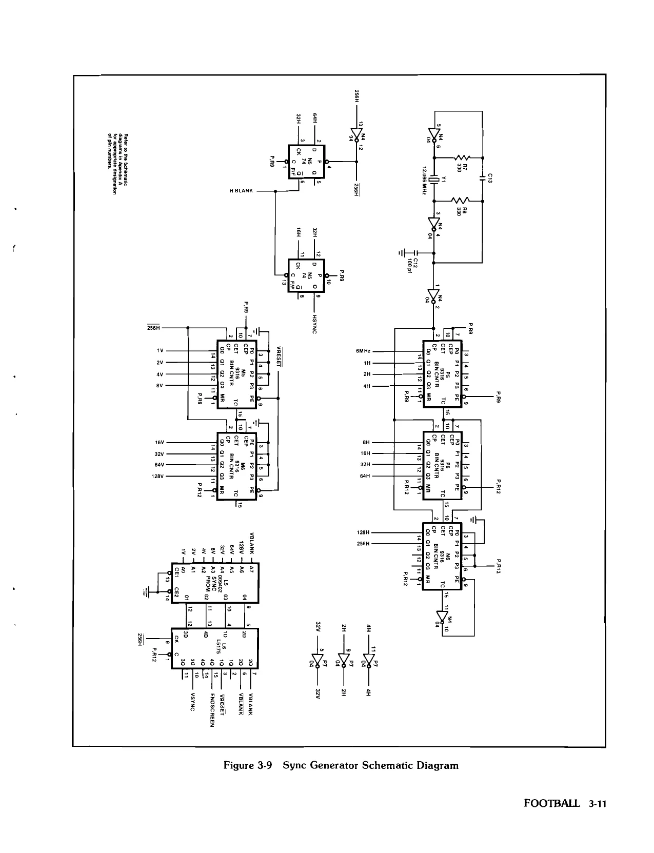
D. SYNC GENERATOR (See Figure 3-9) The base frequency of the sync generator is a 12.096-MHz clock, generated by a crystal-controlled oscillator consisting of crystal Y1, inverter N4 and several discrete components. The output of this oscillator is 12 MHz. Examination of this signal with an oscilloscope (at pin 2 of N4) should show the period (or cycle time) to be approximately 83 nanoseconds (.083 microseconds). See Figure 3-9.
This base frequency is then divided down by binary counters P5, P6, N6: it provides the various horizontal synchronization frequencies (1H through 256H). The final output of this horizontal counter chain is 256H (at pin 13 of N6). This signal is in effect a division of the base frequency (12.096 MHz) by 768, to give a horizontal line frequency of 15,750 Hz. The period of 256H is about 63.5 microseconds. The 256H signal, as well as other horizontal signals, are used to generate the H BLANK and H SYNC timing pulses at flip-flop N5. See Figure 3-11, Horizontal Sync Timing Diagram for the relative timing of these waveforms.
Table 3-1 MPU Input/Output Signal Descriptions
| Signal | | Description/Function | | | Signal | | Description/Function |
| DO-D7 | These eight lines are bi-directional data | RESET | When low, this input line resets the |
bus lines. MPU on either a “power-up condition”
| A0-A15 | These sixteen lines are unidirectional | or a Q, output of the watchdog |
MPU address lines to supporting counter. During the reset sequence memory (i.e., ROMs, RAMs) and 1/0. prior to RESET going high, the con- . tents of two locations (FFFC, FFFD) in This input, when low, indicates an memory are loaded into the MPU pro-
interrupt i the MPU. After the MPU gram counter to point the start of a
concludes its current instruction it will reset routine. proceed to the IRQ sequence.
| R/W | This output is the read and write signal | 00 | Clock input |
line, which indicates the direction of 1,02 | Two-phase, non-overlapping MPU data transfers on MPU data bus. clock outputs.
Table 3-2 Atari Programmed Memory Map
| | 66007 FFF | T PROGRAM | _ | _ |
| 5000 | ~ 7] watches | - | - |
| 4000-4068 | INPUT PORTS. | ~ |
3000 “INTERRUPT ACKNOWLEDGE 2000-2003, OUTPUT PORTS 1000138F 'SCROLLFIELD 1900-19 F [MOTION OBJECT PARAMETERS = O2AG0aFF PLAYFIELD—PLAYER 2 02008256 PCAYFIELD—PLAYER t o000.01FF WORKING RAN
| weuTouirarronts | [oy | [oe | [be] | ee | | | sf | eo |
2000(0UT 0) SCROLLFIELD OFFSET (¢ BITS)
| 2001(0UT 1) | SPARE | eran | SPARE | nicer | HT | WHISTLE |
| metre | arreacr| SR | Noise AwpuTUDE | ||
| 2003 (0UT 3) | SPARE | Leo CATHODES (4 BITS) |
END TRACKBALL DIRECTION
| s000(NO}CTALD = 0 | | COIN | ELEC | |||
| No) | ETRE | 1 | [screen] | SMM | SELECT GTSaD | [tiv> | PLZHD | PLaVD |
| 4000 ano) CTALD = 4 | TRACK-BALL VERT. + | TRACKBALL HORIZ + | |||
| aoo2qwactan =o | | com2 | test | spare | |sevect2)—— | TION SW | ; | |
| 4002 Nz) CTRLD = 1 | TAACK-BALL VERT. 2 | TRACK-BALL HORIZ.2 |
MOTION OBJECT PARAMETERS 1360 MOTION OBJECT 1 PICTURE» 19ct MOTION OBJECT 1 VERTICAL POSITION
1960 ‘MOTION OBJECT 1 HORZONTAL POSITION 1ac3 MOTION OBJECT 2 VERTICAL POSITION
13e SPARE [race MOTION OBJECT ZICTURE #
132 MOTION OBJECT 2 HORIZONTAL POSITION 1965 SPARE 490E MOTION OBJECT 16 PICTURE F 1a0F MOTION OBJECT 1s VERTICAL POSITION TOE MOTION OBJECT 16 HORIZONTAL POSITION 19FF ‘SPARE
FOOTBALL 3-7
+
ABUS'S
Apust4
Asus? PR aust Refer to the Schematic diagrams in Appendix A for appropriate designation of pin numbers.
| aousi) | Pe | asus |
a
| a | x | ‘ABUSI0 | ABUSIO | ||
| +0V | RIO | = | ABUSE | PRZ | ABUSS |
mR A
| ne | seuss | oe | asuse |
po =
| WaTeHDO [5 | eset L | mu | eee | |
| RISABCE | oo | Tae | ||
| aR | + | Bs | usr | asus |
| al | uy | ‘ABUSE | 18H | ‘ABUSE |
| 3) Ve | p | - | ||
| 5 | OY | 5 | mus | puss |
| ro | Ik | asuse | av | suse |
ov = i
| 11 FOZ RIT RBZ] | © | a | ABUS3 | ey | ABUS3 |
vey Hae
| A890 | FEO) | ; | |||
| an | Doh | awsr | asus | ||
| Gaon acco | r@ | Is | oust | wv | sous: |
ats Te iO)
| = | asuso | av | asus |
ae fin aac
| + | aru | gor |
nese
ous?
ewoscreen oauss
paw
av
InTROR
ay cs \ tt 42} 00 WRITE
Figure 3-5
3-8 FOOTBALL Microprocessor Schematic Diagram
‘PROW pROGRAW NeWoRY Z roueu ‘shorn o, Lowes chic TOW PROSAA NeNoR [row cups) “22 VERSION
A)PROGRAM MEMORY
FROM PLAYFIELD /- DATA BIT MUX (
yo vine, GENERATOR eircurTry
SYNC COUNTER. C. Game
\ prom aM Hs ©) GRAPHICS MEMORY
‘SFwROS (SCROLLFIELD WAITE)
PLayFieLo AOORESS BITS
(SeNCIADORESS) PEAR? naw (& CHIPS) [oaracur— PFD 0-3, 6-11, 16-19, 24-27 oauses {TATE Fated ky le
RAM (CHP) TELE ; : ones DATAOUT—) PFD 4-7, 12-18, 20-23, 26-31
SFWRP.(SCROLLFIELO WRITE)
C)PROCESSOR, SCROLLFIELD, MOTION OBJECT (REABIWAITE) MEMORY
ALPHA AND WORKING Raw ROW MPU a ie ‘AND une ca
TRans. RECEIVER
ToaeHa
NOMERICS PROM
EWR PLAYFIELD WRITE)
WORKING AND ALPHANUMERICS | READIWRITE) MEMROT
FROM MPU
ALpHA NUMERICS. 0 ViDEO PROM (NT) SOMMING AND eircurr Reriiy REFOV RELATED. ReFiAy cercumray
WREFoNTL
ALPHABLANK ©) ALPHANUMERICS PROM MEMORY
Figure 3-6 Memory Block Diagram
FOOTBALL 3-9
seuss gp
Figure 3-7 Address Decoding
750KHz
4H (1 CYCLE)
PS PIN 11
©0(4H) 3 PIN 37
Bo2 D3 PIN4
Figure 3-8 0 Clock Driver Signal
The H SYNC signal is used to clock two stages of vertical sync counters MS and M6. This H SYNC signal is divided down by these counters to form the various vertical synchronization frequencies (1V through 128V). These two stages of vertical counters are used, in effect, to do a divide by 262 of the H SYNC signal. This results in the final output of these counters (128V at pin 11 of M6) to be a signal at a frequency of 60 Hz (the period is
3-10 FOOTBALL approximately 16.6 milliseconds). The various vertical frequencies address a sync PROM (L5) whose output data is latched by latch L6. The outputs of this latch are the various polarities and phases of the vertical timing frequency used to synchronize the TV monitor display. These signals all run at a frequency of 60 Hz. See Figure 3-12, Vertical Sync Timing Diagram, for the relative timing of these waveforms.
This page is a drawing, shown as the original scan.
j VERTICAL S*NC HORIZONTAL SYNC PULSES poeere.
avazev CRYSTAL: 12.096 MHZ (Y1) CRYSTAL HORIZONTAL
V BLANK
CONTROLLED SYNC HORIZONTAL
OSCILLATOR COUNTER VERTICAL,
(Na) (P5,P6,N6) Vv SYNC
aucun ———> ENDSCREEN Roles to me Schematic
itry ‘ircuit Figure 3-10 Simplified Diagram of Crystal-Controlled Oscillator and TV Sync C
3-12. FOOTBALL
| 16H | LULU | LLL | LLIN. | ] | ||
| 3H | LJ | LS | LIF | LSP | LIS | Ly |
| oH | Lief | LF | Lies | L |
128H <4 63.5 MILLISECONDS ——_—————_»| 256H
HBLANK PLAYFIELD DISPLAY
usync ———MM
Figure 3-i1 Horizontal Sync Timing Diagram
| v | TUUUU | ULL | ||||
| w i | ILS | LPF | ter | eres | ier | ure |
aw FS Lf Le Sf Ley ob a A cc
VBLANK
VBLANK
VSYNC 128V 16.3 MILLISECONDS —————_=> <—_—_______—_ PLAYFIELD DISPLAY _____ mL
VRESET ——__—
Figure 3-12 Vertical Sync Timing Diagram
The end result of the horizontal and vertical timing waveforms is to synchronize the TV monitor display. This display consists of 262 horizontal lines per frame, with each line being the time equivalent of 768 12 MHz clock pulses. Each frame is repeated 60 times per second, providing the necessary frequency of display refresh that provides a stable non-flickering display. E. ALPHANUMERIC GENERATOR
(See Figure 3-13 and 3-14) Alpha and numeric characters are displayed as 8 line by 8 bit blocks of video at the scoreboard display area of the TV monitor screen. These alphanumeric characters
FOOTBALL 3-13
are stored in PROM N7 (See Figure 3-14) which is accessed by addressing the data from the RAM (M2, N2). The microprocessor loads the alphanumeric location bits into the RAM. The RAM outputs (RAM 0-7) are then temporarily latched by latch M7 at the rising edge of the 4H clock. The latch output bits then address the alphanumerics PROM N7 (at address inputs A4-A9) and address one of the 64 different pictures stored in it. The vertical reflect signals (REFL4V, REFL2V, REFL1V) and the horizontal reflect control signal (HREFLCNTL) and sync signal 4H determine which of the 8 lines of the character is currently being addressed.
The reflect signals determine the alphanumeric image rotation which is displayed at either end of the TV monitor screen facing the player.
The 4-bit paralle! output of alphanumeric PROM N7 is then converted into serial data by shift register P8 and summed into the video output circuitry. Shift register P83 is gated by NAND gate N9, which is controlled by the ALPHABLANK window signal.
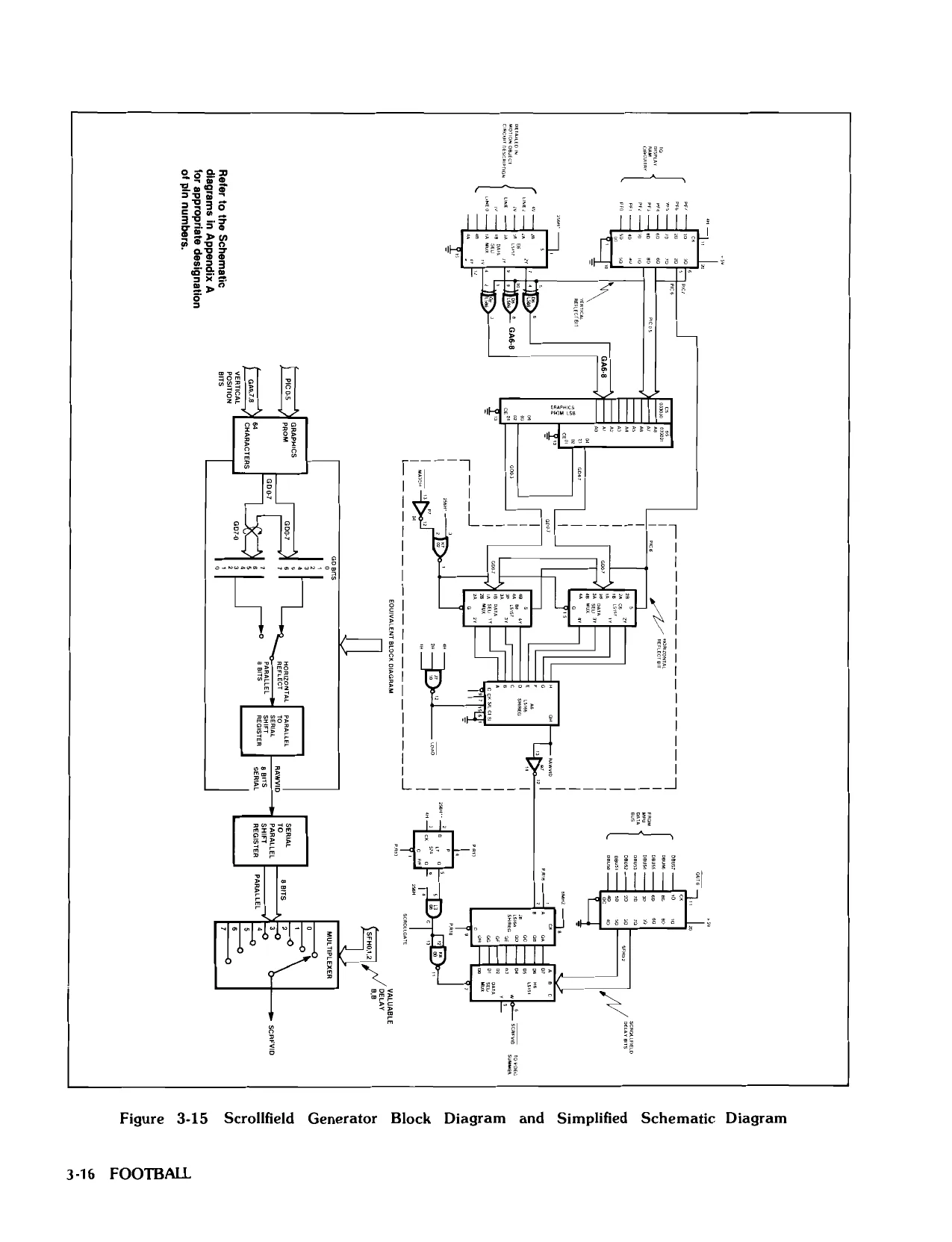
F. SCROLLFIELD GENERATOR (See Figure 3-15 and 3-16) The scrollfield generator generates the scrolling playfield video. The video is actually generated by the data stored in the graphics PROM comprised of PROM devices C5 and DS. See Figure 3-15. This PROM video information is addressed by data from the playfield display RAM. The method by which the MPU writes the appropriate scrolifield data to each RAM location and then the horizontal and vertical timing signals read this data out for actual video generation is known as “cycle sharing”. The
64,8 BIT x 6 LINE ALPHA AND NUMERIC CHARACTERS
REFLECT Bis PLAYFIELD WRITE circuitry that controls this “cycle sharing” technique selects one of 3 sets of addressing information to address the display RAM.
This circuitry functions as follows:
- When buffered MPU clock B¢2 is high, the MPU address bus (AQ-A15) addresses various playfield display RAM locations, and writes appropriate scrollfieid picture codes into them via the MPU data bus (DO-D7).
- When B@2 is low and 256H is low, horizontal sync signals (8H, 16H, 32H, 64H) are enabled to address the RAM. This is used for motion object display.
3. When B® 2 is low and 256H is high, the vertical sync
signals (16V, 32V, 64V, 128V) and the shifted horizontal sync signals (SFH3, SFH4, SFH5, SFH6, SFH7) address the playfield. These shifted signals are the result of adding the top 5 bits of the scroll latch, F7, to the horizontal sync functions. They provide a “coarse”, 8 bits at a time, horizontal shift of the scrollfield.
Since the data was read out of the RAM by the horizontal and vertical sync signals, the picture codes PIC 0-7 always correspond to the portion of the monitor display currently being scanned. Because of this, the PIC 0-7 outputs can be used to generate video information for immediate display. These PIC signals address one of 64 8 x 8 pictures stored in graphics PROMs C5 (LSB), D5 (MSB). The output of the PROMs is then converted to serial video information: by shift register A6.
The serial video is then delayed 0 to 7 bit times by variable delay circuit shift register J8 and multiplexer H8. This circuit provides the “fine” horizontal shift of the scroilfield.
Refer to the Schematic diagrams in Appendix A for appropriate designation of pin numbers.
PARALLEL TO SCROLLFIELD SERIAL SERIAL
To VARIABLE DELAY ‘caRCUITRY 4BiTs
CONVERTER
Figure 3-13 Alphanumerics Generator Block Diagram
3-14 FOOTBALL
ase
as+
‘UNosauH
7uNogauH Ast
UND s3uH
ast
g
undwId ‘ONIWNS ‘O3GIA OL
Figure 3-14 Alphanumerics Generator Simplified Schematic Diagram
FOOTBALL 3-15
This page is a drawing, shown as the original scan.
FOOTBALL 3-17 Figure 3-16 Display RAM Simplified Schematic Diagram of pin numbers. Refer to the Schematic dlagrams In Appendix A tor appropriate designation
G. MOTION OBJECT GENERATOR (See Figure 3-17)
The motion object generator produces characters such as the football and the Xs and Os. These motion objects are generated by the same circuitry found in the scrollfield generator (see Figure 3-15), while the actual graphics are permanently stored in PROMs C5 and DS (see Figure 3-17). This circuitry is used for motion objects when 256H is low, and for scrollfield when 256H is high. The RAWYVID signal from the parallel-to-serial shift register AG is connected to OR gate K8. This gate ORs the raw video (RAWVID) from the scrollfield circuitry and the data out (DO) from the RAM K6 which was cleared while the information on that line was being read out. The procedure is as follows for each motion object:
- The horizontal position is latched at J5. It is used to set counters K5 and J6 to the desired start position.
- The vertical line number is effectively subtracted from the vertical position by adders F5, HS. The H5 produces a match signal if the object is visible on this scan line. It also produces the LINE 0, LINE 1 and LINE 2 signals which select one of eight scan lines within an object.
- The LINExx signals, together with the picture code, PIC 0-5, are used by the graphics circuitry to produce the RAWVID as previously discussed.
MULTIPLEXED a ens
VERTICAL SYNC cOuNTER
- The 8-bits of RAWVID are ORed with any existing data in RAM (K6) from previous objects and placed in the RAM at the address latched in J5, and the next seven serial addresses.
These steps are repeated for each of the 16 motion objects during the time 256H is low. The HCLR signal then resets the K5 and J6 counters. The data is read out of the RAM as MVID while 256H is high. The location is read and its contents are sent to the video circuit. The RAM is cleared by output of AND gate L8 prior to the next data line.
H. TRACKBALL CONTROL AND SWITCH INPUT CIRCUITRY
(See Figure 3-18)
The trackball control and switch input signals are multiplexed as illustrated in Figure 3-19. This multiplexing is accomplished by alternately selecting the mode of operation for the pre-settable counters D9, D10, H10, and H9. When the counter load signal (CTRLD) goes low, it reads the switch status by loading a preset count into the counter inputs (A, B, C, D) and then latching and outputting the data into buffer E10. When CTRLD goes high the trackball control signal toggles the counter either in a count up or a count down direction. The counter outputs then are gated via E10. Both trackball and switch signals are then sent to the microprocessor via the data bus (DO - D7).
Reter to the Schematic diagrams in Appendix A for appropriate designation of pin numbers.
(wononraL REFLECT am)
‘arapnics circuraY boc. (REFER TO _=Swavay a PY FIGURE 3.15)
MULTIPLEXED DISPLAY Ram airs (MOTION oBsECT | viveo To vineo ‘SUMMING CIRCUM
Monon ‘OBuecT
Figure 3-17 Motion Object Generator Block Diagram
3-18 FOOTBALL
romeo whee vee
Stowe
oreaxron ‘serenes {oPriom. Test E10)
cara wus
orenaran ments {ornom, test ET)
oma Mictovexee
Reter to the Schematic diagrams in Appendix A for appropriate designation of pin numbers,
Figure 3-18 Trackball Control and Switch Input Simplified Schematic Diagram
FOOTBALL 3-19
J. VIDEO OUTPUT (See Figure 3-19) The video output circuit receives all the video signals (MVID, SCROLLGATE, SCRFVID, ALPH, and related sync signals) and gates these signals logically summed at the Q1 emitter follower device (2N3643). The signal at the emitter of the transistor then becomes the composite video signal sent to the game's TV display monitor.
K. AUDIO GENERATOR AND AMPLIFIER (See Figure 3-20) The audio generator produces ithe crowd, whistle,and ball sounds. The crowd sound is the result of the gated random noise generator composed of shift registers A8
3-20 FOOTBALL and B8. The NOISE output of this generator is gated “on” each time the KICKER signal goes high. The KICKER signal is developed by the microprocessor via LATCH F8. The crowd sound volume is automatically controlled by the data bus bits DBUS 0-5. The noise (unfiltered crowd sound) is then filtered by the active bandpass filter circuit comprised of one-half of Op-Amp A9 (LM324). The other half of A9 is the audio mixer which sums the hit, whistle and the crowd sounds. The whistle sound is generated by VCO control bit 1Q of F8 which gates the VCO “on”, therefore producing the whistle sound
The output of the audio mixer AQ is then amplified by the TDA-1004 audio amplifier device. Potentiometer R75 controls the level of audio output.
FROM SCROLLFIELD
GENERATOR
FROM SCRFVID
ALPHANUMERICS: a GENERATOR ——————> ALPH
SCROLLGATE
FROM MOTION
OBJECT GENERATOR »
SCRFVIO
Refer to the Schematic
diagrams in Appendix A for appropriate designation of pin numbers.
VBLANK* VBLANK* HSYNC VSYNC
a | VIDEO SUMMING CIRCUIT EMITTER ‘@ FOLLOWER
VIDEO OUT TOTV MONITOR CHASSIS
Figure 3-19 Video Circuit Simplified Schematic Diagram 3-21 FOOTBALL
FROM MPU DATA BUS | nena | | VOLTAGE oo CONTROLLED | oscntator
RICKER
FROM MPU DATA BUS i
i ! ! ! i i I
!
b i I pe YL) Li ----—-- + 285
220K
RANDOM NOISE GENERATOR Vactive 'BaNDPass | AUDIO FILTER Loscoe____..
SPEAKER
= AUDIO AMPLIFIER
Li Reter to the Schematic
3-22 diagrams in Appendix A for appropriate designation of pin numbers.
Figure 3-20 Audio Generator and Amplifier Simplified Schematic Diagram
Due to its solid-state electronic circuitry, this Atari unit should require very little maintenance and only occasional adjustment. Information given in this chapter and elsewhere in this manual is intended to cover most servicing situations that may be encountered at the game site. The procedures given are in sufficient detail to be understood by a person with moderate technical background.
~
FOOTBALL
“~e
A. CLEANING
The exteriors of game cabinets and Plexiglas® panels may be cleaned with any non-abrasive household cleaner. If desired, special coin machine cleaners that leave no residue can be obtained from your distributor. Do not dry-wipe the acrylic plastic panels, because any dust can scratch the surface and result in fogging the plastic.
B. COIN MECHANISM Components On Coin Door Figure 4-1 shows the back side of the coin door assembly where the game’s two coin mechanisms are mounted. Included is the lock-out coil assembly; the lock-out wires are connected to this assembly but are hidden behind the coin mechanisms. Powering the game causes the lock-out wires to retract far enough to allow genuine coins to reach the coin box. When AC power to the game has already been turned off, the lock-out coil is de-energized, causing the lock-out wires to move out far enough to divert coins to the return chute.
Directly below each coin mechanism is a secondary coin chute and a coin switch with a trip wire extending
LOCK-OUT COIL LAMP HOLDER
Figure 4-1 Coin Door Assembly
4-2 FOOTBALL out to the front edge of the chute. When the trip wire is positioned correctly, a coin passing down the secondary chute and into the coin box will momentarily push the trip wire down and cause the switch contacts to close.
Also shown in the photograph is a slam switch assembly. It has been included to defeat any players who might try to obtain free game plays by violentiy pounding on the coin door to momentarily close the contacts on a coin switch. The slam switch contacts connect to the microcomputer system, which will ignore coin switch signals whenever the slam switch contacts are closed.
Access to Coin Mechanisms To remove jammed coins, and for maintenance cleaning, each magnet gate assembly can be hinged open without removing it from the door, as shown in Figure 4-2. Or, if necessary, each coin mechanism can be entirely removed from the door merely by pushing down on a release lever and simultaneously tilting the mechanism back, then lifting it up and out. This is shown in Figure 4-3.
Plexiglas® is a registered trademark of Rohm & Haas Company.
Figure 4-2 Hinging Open the Magnet Gate Assembly
Figure 4-3 Removal of Coin Mechanism
Cleaning of Coin Paths
By talking to many operators, we have found that the best method of cleaning a coin mechanism is by using hot or boiling water and a mild detergent. A toothbrush may be used for those stubborn buildups of residue. After cleaning, flush thoroughly with hot or boiling water, then blow out all water with compressed air.
Figure 4-4 shows the surfaces to clean inside the coin mechanism. These include the inside surface of the
(CLEAN BOTH SURFACES WHERE COIN ENTERS THE MECHANISM, AS WELL AS THE MAGNET)
Figure 4-4 Surfaces to Clean Inside the Coin Mechanism mainplate, and the corresponding surface of the gate assembly. There may also be metal particles clinging to the magnet itself. To remove these you can guide the point of a screwdriver or similar tool along the edge of the magnet.
if coins are not traveling as far as the coin mechanisms, you will need to clean the channel beneath the coin slot. To gain access to this channel, use a 3/8-inch wrench and remove all three nuts that secure the cover plate (refer to Figure 4-5). Removing the plate will provide access to the entire channel.
Also clean the inside surfaces of the secondary coin chutes, but when doing this be careful not to damage or bend the trip wires on the coin switches.
Figure 4-5 Removal of Plate Covering Rear of Coin Slot
Lubrication Do not apply lubrication to the coin mechanisms. The only points that may need lubrication {and only rarely) are the shafts of the scavenger buttons (coin rejection buttons) where they pass through the coin door. Apply only one drop of light machine oil, and be positive that no oil drops down onto a coin mechanism. Figure 4-6 shows this lubrication point.
Adjustment of Coin Switch Trip Wire In order for a coin switch to operate reliably when a coin travels down the secondary coin chute, the rest position of its trip wire should be as shown in Figure 4-7. Use extreme care when handling or touching these wires.
FOOTBALL 4-3
MANUALLY HOLD DOWN REJECTION BUTTON AND APPLY ONE DROP HERE
LOCK- OUT WIRE
Figure 4-6 Close-Up View of Lubrication Point
In Figure 4-7 you will note that the coin switch trip wire is oriented into the “V” of the secondary coin chute. The wire should extend to only about 1/8” beyond the chute.
A retaining clip holds the wire onto the switch actuating stud. If you should lose a retaining clip, all is not lost. dust crimp the switch actuating stud over the trip wire with a pair of pliers.
Mechanical Adjustments on Coin Mechanism Coin mechanims are adjusted prior to shipment from the factory and normally will retain these adjustments for many months. If, due to wear or other causes, it becomes necessary to make new adjustments, remove the coin mechanism from the coin door. Then take it toa clean well-lighted area where it can be placed in a vertical position on a level surface (such as a bench top). Besides a screwdriver, you will need a set of several coins, including both new and old, worn ones. Figure 4-8 shows an exploded view of the mechanism and gives procedures for adjusting the kicker, separator, and the magnet gate. These adjustments should only be done by someone who has experience in servicing coin mechanisms and who understands their operation.
4-4 FOOTBALL ‘CORRECTLY ADJUSTED TRIP WIRE
Figure 4-7 Detail View of Coin Switch and Trip Wire
General Troubleshooting Hints
The first action is to look for jammed coins. After these have been removed, examine the coin path for presence of foreign material or loose objects (such as chewing gum, small metallic objects, paper wads, etc.). In cases where game usage is heavy, it may be necessary to clean the entire coin path periodically, in order to prevent build-up of contaminants that can hinder the movement of coins through the mechanisms. Also confirm that the trip wire on each coin switch is intact, and is properly adjusted. If troubles still persist, check the conditions and positions of the lock-out wires, and the mechanical adjustments on the coin mechanisms, before suspecting the electronics. If a coin mechanism rejects genuine coins, try to readjust it. If this is not successful, then replace it with a working mechanism.
ITEM IDENTIFICATIONS 1 Kicker and Separator Screws 2 Washers 3 Kicker 4 Separator 5 Gate Lever Spring 6 Gate Pivot Pin 7 Meinplate Assembly 8 “C” washer 9 Rail 10 Gate Assembly 12 Cradle Assembly
- Upper Gate Pivot Spring 14 Undersize Lever Assembly 15 Magnet Gate Assembly 16 Magnet Gate Adjuster 7 1g Screws 18 Assembly 19 Return Coverplate 20 Coverplate 21 Mounting Studs 22 Lower Gate Pivot Spring 23 Coin Release Lever Kicker and separator
- Set the acceptor with the back of the unit facing you in the test position.
- Loosen the kicker and separator screws (1) and move the kicker (3) and the separator (4) as far to the right as they will go. Lightly tighten the screws.
- Insert several test coins (both old and new) and note that some are returned by striking the separator.
- Loosen the separator screw and move the separator a slight amount to the left. Lightly retighten the screw.
- Insert the test coins again and, if some are still returned, repeat Step 4 until all the coins are accepted.
- Loosen the kicker screw and move the kicker as far to the left as it will go. Lightly retighten the screw.
- Insert the test coins and note that some are returned.
- Loosen the kicker screw and move the kicker a slight amount to the right. Lightly retighten the screw.
- Insert the test coins again and, if some are still returned, repeat Step 8 until all the coins are accepted.
- Be sure that both screws are tight after the adjustments have been made.
Magnet gate
- Set the acceptor with the front of the unit facing you in the test position.
- Turn the magnet gate adjusting screw (16) out or counterclockwise until none of the coins will fit through.
- With a coin resting in the acceptor entrance, turn the adjuster in or clockwise until the coin barely passes through the magnet gate. 4, Test this adjustment using several other coins (both old and new) and. if any fail to pass through the magnet gate, repeat Step 3 until all the coins are accepted.
- Fix the magnet gate adjusting screw in this position with a drop of glue.
Additional Cleaning
- Remove the transfer cradle (12) and the undersize lever (14).
- Use a pipe cleaner or similar effective cleaning tool to clean the bushings and pivot pins
- Replace the transfer cradle and the undersize lever.
- To be certain the coin mechanism is completely free of any residue. place the mechanism in boiling water for several minutes. Carefully remove it and let it air-dry completely before reinstalling in the door.
Figure 4-8 Adjustments on Coin Mechanism
FOOTBALL 4-5
Cc. TV MONITOR ADJUSTMENTS
For best results be sure the game has been turned on for a while before making any TV monitor adjustments
The TV monitor adjustments are accessible through the access door panei of the game cabinet. These adjustments have to be done while the game is energized. Therefore, only persons familiar with safety measures and repair procedures on electrical equipment should perform them.
The TV monitor should be adjusted only when the picture is distorted or if the contrast or brightness seems out of adjustment.
The monitor's adjustments function like those of a conventional, home television set, except that the volume adjustment has no effect. Instead, the game produces its sound in circuits separate from the TV monitor. Figure 4-9 shows the location of the adjustments on both TV monitors used by Atari. Your game contains a TV monitor manufactured to Atari specifications by Motorola, TEC Videoelectronics, or Wells-Gardner. When making adjustments, follow these general guidelines:
BRITE (Brightness) —Perform this adjustment before the contrast. Adjust so that the white lines covering the screen just barely disappear, when the brightness is turned up.
CONT (Contrast)—Adjust so that the images are as bright as possible against the dark background without being blurred.
HORIZ HOLD (Horizontal Hold) or HORIZ OSC (Horizontal Oscillator) — Adjust if the picture is slightly off-center horizontally, if the images appear warped, or if the picture is broken up into a series of diagonal lines. Adjust for a stable, centered picture.
VERT HOLD (Vertical Hold)—This needs adjustment only if the picture appears to be rolling up or down the screen. Adjust for a stable, centered picture.
D. FUSE REPLACEMENT
Football contains eight fuses, five on the power supply assembly in the lower part of the cabinet, one in a clipholder near the power supply, and two on the TV monitor assembly. Power supply fuses are accessible through the access door assembly. TV fuses are also ac-
(e) : Bg het CONTRAST ear veer uw 2 FUSES REMOVE cowtnast T Concurwess srignr? NEIGHT thom 08 quer Sse woniz ose _ won hoLo- \veaT wou
TEC MOTOROLA MODEL TM- 600/623 MODEL M5000/M7000
Figure 4-9 Locations of Adjustments on TV Chassis
4-6 FOOTBALL
cessible through the access door. Replace fuses only with the same type as follows:
Wells-Gardner 19V1001/22V1001 Monitors: 3AG 1.5-amp Slow-blow 3AG 0.75-amp Slow-blow TEC TM-600/623 Monitors: 3AG 2-amp and 0.5-amp quick-blow, 250 volts Motorola M5000/M7000 Monitors: 3AG 0.8-amp quick blow, 250 volts Power Supply: Fuses Fl and F2—3AG 3-amp slow-blow, 250 volts Fuses F3 and F€—3AG 2.5-amp slow-blow, 125 volts Fuse F5—3AG 8-amp fast-blow, 125 volts Clip near power supply: (shown in harness schematic) 2.5-amp Slow-blow
E. CONTROL PANEL REMOVAL (See Figure 4-10) Prior to replacing any removable component from the control panel, follow the steps outlined in Figure 4-10. F. TV MONITOR REMOVAL (See Figure If the TV monitor proves to be at fault, remove the monitor as shown in Figure 4-11.
G. TRACK BALL ASSEMBLY REMOVAL (See Figure 4-12) Refer to paragraph E before replacing the track ball assembly.
H. PLAY SELECT BOARD ASSEMBLY REMOVAL (See Figure 4-13) Refer to paragraph E before replacing the play select board assembly.
CONTROL PANEL REMOVAL
- Unfasten and remove three allen-head screws from control panel.
- Swing the contro! panel open.
Figure 4-10 Control Panel Kemoval
FOOTBALL 4-7
TV MONITOR REMOVAL
- Remove control panel located to the right of the coin mechanism as illustrated in Figure 4-10, Remove glass playfield shield. Remove cardboard bezel. Open access door. Unplug contro/ panel Molex connectors for both player control panels. Unfasten and remove the two TV monitor carriage bolts.
- Unplug TV monitor chassis connecior. gPen
&
- Slide out TV monitor shelf assembly (the opened control panel is attached to the assembly).
TRACKBALL ASSEMBLY REMOVAL
Remove control panel as illustrated in Figure 4-10. .__ Unfasten and remove three (3) trackball 82° flathead countersink screws from assembly. Remove the trackball assembly.
BALL REMOVAL
- Untasten and remove four (4) countersink machine screws from trackball assembly top plate. Remove and/or replace the ball.
STEERING CONTROL PCB
._Unfasten and remove two (2) pan head machine screws associated washers and hex nut from either of two steering PCB assemblies.
- Remove troublesome PCB assembly.
Figure 4-12 Track Ball Assembly Removal
4-8 FOOTBALL
PLAY SELECT BOARD ASSEMBLY REMOVAL
Remove control panel as illustrated in Figure 4-10. Unfasten and remove two washers and nuts. ‘Unplug Molex connector. Remove board. Replace lamp if necessary.
Figure 4-13. Play Select Board Assembly Removal
NORMALLY CLOSED (N.C.) CONTACTS
CONTROL,
SWITCH
TURN COUNTERCLOCKWISE TO REMOVE
LIGHT-EMITTING DIODE (L.€.D.) CONTACTS
NORMALLY OPEN (N.0.) CONTACTS
- Remove all wires from the suspected switch. No
- Turn the switch counterclockwise while holding — the cone- shaped nut od the outside of the ; game cabinet. . it i DOUBLE-POLE SINGLE-THROW Install a new switch using the reverse (PST) SWITCH WITH procedure.
- Reconnect the harness wires. INTERNAL LED
Figure 4-11 LED (LICON) Play Select Pass Switch Removal
J. LED (LICON) PLAY
SELECT / PASS SWITCH REMOVAL (See Figure 4-14)
Refer to paragraph F before replacing the LED play select/pass pushbutton switch.
The LED switches on the front panel have a very low failure rate. In case either switch should ever be suspect, first test it. To test the switch perform the following steps:
Uniock and open the coin door. Remove the wires from the suspected switch. Set multimeter to ohms scale. Set ohms scale toR x 1, then zero the meter. Rene
- Connect multimeter leads to appropriate LED switch contacts. (See Figure 4-14 for designation of switch contacts and meter lead placement.)
- Check contacts (push and release the switch button) for closed and open continuity.
- If the contacts do not operate sharply or always remain closed or open, then replace the LED switch as outlined in Figure 4-14.
Kk. BASE ASSEMBLY REMOVAL (See Figure 4-15) The base assembly to the cabinet may be removed when desired. For example, by removing the cabinet base assembly, the playfield is lower, therefore facilitating the placement of lounge chairs near the player controls like with other Atari cocktail table games.
MAIN CABINET ASSEMBLY
Figure 4-15 Base Assembly Removal
4-10 FOOTBALL
ILLUSTRATED PARTS CATALOG
The purpose of this chapter is to provide you with the necessary information for ordering replacement parts for the Football game.
When ordering parts from your distributor, give the part number, part name, applicable figure number of this catalog, and serial number of your Football game. This will help to avoid confusion and mistakes in your order. We hope the results will be less downtime and more profit from your game.
FOOTBALL
NOTICE TO ALL PERSONS RECEIVING THIS DRAWING CONFIDENTIAL Reproduction. forbiaden. without the Specific winten permission of Atah. Inc.. Sunnyvale California” This arawing 's only conaitionally issued. and neither receipt nav possession thereat conters or transters, any Nght in oF fc Sawing of any ne? e t0 vse, the subject matter of the mn or Igenorea formation shown is drawing or any part 5 vendors oF Ata’ incor of > ah 10 reproduce tnis drawing Is grantes if alter hereof uniess by writen agreement swum or writen permission rom the corporate
NARROW LIP THIS SIDE
Figure 5-1 Football Final Assembly A033580-01 D
5-2. FOOTBALL LID
F
- 2 CRO 5 G2) eeran (5) B
- 4 READ sc § 4 a / - 40) 8 can
SECTION A\=A\
THE FOLLOWING ITEMS ARE NOT SHOWN (49) @8) (28) 2)
Figure 5-1 Football Final Assembly Parts List ATARI’
| Item | Part Number | Qty. | Description |
| 1 | A033529-01 | 1 | Cabinet Assy. with Graphics |
| 2 | A033578-01 | 1 | Assy., Monitor |
| 3 | A030867-01 | 1 | Assy., R.F. Shield Enclosure |
| 4 | A009083-01 | 1 | Coin Door Final Assy. |
| 5 | A007197-01 | 1 | Power Supply Assy. |
| 6 | 009549-01 | 1 | Coin Door |
| 7 | A033582-01 | 2 | Assy., Control Panel with Graphics |
| 8 | 033588-01 | 1 | Shield with Graphics |
| 9 | 033477-01 | 1 | Bezel with Graphics |
| 10 | 46-2022502 | 1 | Fuse, 2.5 AMP (Slow Blow) |
| an | 033098-01 | 1 | Stop |
| 12 | 002728-01 | 2 | Bracket, Panel, Mounting |
| 13 | 004131-02 | 1 | Fan Grill Mesh |
| 14 | A022016-01 | 1 | Strain Relief Power Cord Assy. |
| 15 | 007103-01 | 1 | On-Off Switch Cover |
| 16 | A030978-01 | 1 | Assy., Atari Football P.C.B. |
| 17 | A033254-01 | 1 | Assy., R.F. P.C.B. |
| 18 | A033323-02 | 1 | Main Harness and Component Assy. |
| 20 | 48-004 | 1 | Speaker, 5” |
| 21 | 000869-01 | 1 | Speaker Grill |
| 22 | 032570-01 | 1 | Coin Box Enclosure |
| 23 | A009548-01 | 1 | Assy., Coin Box Lid |
| 24 | 46-202302 | 2 | Fuse, 3 AMP (Slow Blow) |
| 25 | 005233-01 | 1 | Rear Door Seal |
| 26 | 033613-01 | 1 | Bag, Instruction Manual |
| 27 | TM-126 | 1 | Tech Manual and IPC |
| 28 | 78-13025 | AIR | 3M Sealer 5354 |
| 35 | 73-77015 | 4 | Rivet, 3/16 x .68 (Black) |
| 36 | 75-5516B | 4 | Bolt, Carr., %4"-20 x 1.00 Lg (Black) |
| 37 | 75-015S | 12 | Washer, Flat, 4” |
| 38 | 75-990505S | 4 | Nut, Lock, Shallow Pat., Nylon 1%” |
| 39 | 72-6610S | 23 | Screw, S.M.P.H., Phil., #6 x 5/8” Lg. |
| 40 | 72-6812S | 8 | Screw, S.M.P.H., Phil., #8 x 3/4” Lg. |
| 41 | 72-6810S | 6 | Screw, S.M.P.H., Phil., #8 x 5/8” Lg. |
| 42 | 82-8516 | 6 | Screw, Mach., Allen, Button Hd., %-20 x 1.00 Lg. |
| 43 | 75-935 | 2 | Wingnut, Steel, 4-20 |
| 44 | 72-6012S | 1 | Screw, S.M.P.H., Phil., #10 x 3/4” Lg. |
| 45 | 75-010S | 3 | Washer, Flat, #10 (Steel) |
| 46 | 75-5520B | 8 | Carr. Bolt, %"-20 x 1.25” Lg. (Black) |
| 47 | 75-045S | 2 | Washer, Splitlock, 4” |
| 48 | 75-915 | 6 | Nut, Mach., Hex, %”-20 |
| 49 | 75-931 | 8 | Wingnut, Steel, 10-24 |
| 50 | 75-5120B | 2 | Bolt, Carriage, 10-24 x 1.25 Lg. |
| 51 | 75-040S | 2 | Washer, Splitlock #10 |
| 52 | 72-6608S | 4 | Screw, S.M.P.H., Phil., #6 x %2” Lg. |
5-4 FOOTBALL
/oO
Figure 5-2 TV Monitor Assembly A033578-01 D \ 4 2EQD
APPLY R.T.V SILICONE RUBBER (GE 108 OR ma OAN Oe
EQUIV) AS SHOWN, ON ONE SIDE.
LOCATION OF COPYRIGHT DECAL MAY
CHANGE AT THE DISCRETION OF MANUFAC. TURING.
FOOTBALL 5-5
ATARI’ Figure 5-2 TV Monitor Assembly Parts List
| Item | Part Number | Qty. | Description |
| 1 | A033065-01 | 1 | Assy, Monitor Support |
| 2 | 90-032 | 1 | Monitor 23” Diagonal Black and White |
| 3 | 005594-01 | 4 | Monitor Tie-Down Brkt. |
| 4 | 48-004 | 1 | Speaker 5” |
| 5 | 000869-01 | 1 | Speaker Grill |
| 6 | 73-77015 | 8 | Rivet 3/16 x .68 (Black) |
| 7 | 72-6610S | 6 | Screw SMPH #6 x 5/8” Lg. |
| 8 | 72-6812S | 8 | Screw SMPH #8 x 3/4” Lg. |
| 9 | 006313-03 | 1 | Copyright Decal 1978 |
| 10 | 004131-02 | 1 | Fan Grill, Mesh |
(> Were: communicarens Company
5-6 FOOTBALL
SOOY
o
Ceeeesl) eee n o
Figure 5-3 Type B Power Supply A007197-01 D
FOOTBALL 5-7
Figure 5-3 Type B Power Supply Parts List ATARI
| item | Part Number | Qty. | Description |
| 1 | A009266-01 | 1 | Power Supply Base Weldment Assembly |
| 2 | A006886-01 | 1 | Transformer Termination Assembly “Type B” |
| 3 | 29-053 | 1 | Cap., Sprague Electrolytic 26,000 uf @ 15V |
| 4 | 78-70501SC | 1 | Brkt., Cap. Mtg. Sprague #4586-48 |
| 5 | A006555-01 | 1 | P.C. Board Rectifier |
| 7 | 79-4411004 | 5 | Fuse Holder, Panel Mounting |
| 8 | 41-2003 | 1 | Filter, Power Line, 5 AMP |
| 9 | A006958-01 | AJR | Volt Selection Block 95V |
| 10 | A006958-02 | AIR | Volt Selection Block 110V |
| 1 | A006958-03 | AIR | Volt Selection Block 205V |
| 12 | A006958-04 | AIR | Volt Selection Block 220V | |
| 13 | 78-2708 | 1 | Grommet, Plastic |
| 14 | 72-1810S | 9 | Screw Pan Hd., #8-32 x 5/8” Lg. |
| 16 | 75-048 | 9 | Washer, Split-Lock #8 |
| 17 | 75-918S | 9 | Nut Hex #8 |
| 18 | 75-018S | 8 | Washer Flat #8 |
| 19 | A007192-01 | 1 | Power Switch Termination |
| 20 | A007444-01 | 1 | Power In Harness |
| 24 | 46-203801 | 1 | Fuse, 8 AMP, 125V, 3 AG Fast Acting |
| 22 | 46-201251 | 2 | Fuse, 22 AMP, 125V, Slow Acting |
© & saree Conmimcatons Comeany
5-8 FOOTBALL
- 6 PLCS
@ ' ©
2 PLCS @1) ~ ,
ee (3) 2 PLCS 2 PLCS @2) > ( : : S 2 PLCS ‘ 2 PLCS
@)
- 2 PLCS
YEL YEL/BK:
BK/YEL (2)4 PLCS
NOTICE 70 ALL PERSONS RECEIVING THS DRAWING CONFIDENTIAL: Reproduction. forbidden withoul the Specitic written. permission of Alar. ine.. Sunnyvale Calriornia” This drawing 13 only conditional) issued. and neither receipt nor possession thereat conters ortransiers, Sry right in, of Heense 10 Use, the subject matter af the Gaming oF any dasigh oF technical information shown “hereon, aor any night fo repreduce inis drawing or any pat thereat, except formanulactute by vendors of Alan Inco" porated and for manufacture under the corporation's wit. Ten license, no "ght to reproduce this drawing 1s granted forthe subject matter Ihermol unless by writen agreement ‘eutn oF weiten permission trom Tne corporation
Figure 5-4 Coin Door Assembly A009083-01 F
FOOTBALL 5-9
A ATARI
| Item | Part Number | Qty. |
| 1 | A007637-01 | 1 |
A007637-02 Ref. A007637-03 Ref. A007637-04 Ret. A007637-05 Ref. A007637-06 Ref. A007637-07 Ref.
| 2 | 75-9165 | 4 |
| 3 | A030362-01 | 1 |
| 4 | A007640-01 | 2 |
| 5 | A002465-01 | 1 |
| 6 | 004320-01 | 1 |
| 7 | 004341-01 | 2 |
| 8 | 004344-01 | 1 |
| 9 | 004340-01 | 2 |
| 10 | 004337-01 | 2 |
| W | 004338-01 | 1 |
| 12 | 004336-01 | 1 |
| 13 | 004326-01 | 2 |
| 14 | 75-046 | 4 |
| 15 | 006904-01 | 2 |
| 16 | 007359-01 | 1 |
| 17 | 70-11-47 | 1 |
| 18 | 73-3008 | 2 |
| 19 | 75-9914001 | 6 |
| 20 | 75-0268 | 4 |
| 21 | 75-00516 | 13 |
| 22 | 008629-01 | 2 |
| 23 | 71-2118 | 1 |
| 24 | 71-1225CU | 2 |
71-125FB Ref. 71-1205FF Ref. 71-1201MG Ref. 71-1201KS Ref. 71-1210PE Ref. 71-1220CA Ref.
| 25 | 007753-01 | 1 |
| 26 | A007638-01 | 1 |
| 27 | A006921-01 | 1 |
Figure 5-4 Coin Door Assembly Parts List
Description
Front Bezel Assy.—Used only on -01 Coin Door Assy. Front Bezel Assy.—Used only on -02 Coin Door Assy. Front Bezel Assy.—Used only on -03 Coin Door Assy. Front Bezel Assy.—Used only on -04 Coin Door Assy. Front Bezel Assy.—Used only on -05 Coin Door Assy. Front Bezel Assy.—Used only on -06 Coin Door Assy. Front Bezel Assv.—Used only on -07 Coin Door Assy. See Figure 5-5 Nut, 6-32 Coin Lock-Out Assembly, See Figure 5-6 Coin Switch Assembly, See Figure 5-7 Coin Counter Assembly Coin Door Weldment Secondary Coin Chute Key Loop Spring Return Bracket, Wire Form Lock-Out, Wire Form, R.H. Lock-Out, Wire Form, L.H. Button, Scavenger Lock Washer, #6 Spacer Lamp Socket Lamp Retaining “C” Ring, Truarc #5103-25 Self-Threading Nut, Tinnerman #SR188006 Washer, #6 Kepnut, Style 842, Stl., 6-32 Spring Lock Assembly, Hudson Lock Coin Mechanism for American Quarter Only Coin Mechanism for Belgian 5 Francs Only Coin Mechanism for German Mark Only Coin Mechanism for Swedish Krona Only Coin Mechanism for Japanese 100 Yen Only Coin Mechanism for English 10 Pence Only Coin Mechanism for Australian 20-Cent Piece Only Plate, Anti-Probe Switch Assembly, Slam Harness Assembly
5-10 FOOTBALL
NOTICE TO ALL PERSONS RECEIVING THIS DRAWING CONFIDENTIAL: Reproduction forbidden without the Specific written permission of Alan, Inc. Sunnyvale, California’ This drawing 1s only conditionaly issued, and neither receipt nor possession thereo! confers or ianslers
wath or written permission from the corporation.
[ Item Part Number Qty. Description
| 1 | 004328-01 | 1 | Bezel |
| 2 | See below | 2 | Ring |
| 3 | 004331-01 | 2 | Coin Shield |
| 4 | 004332-01 | 2 | Primary Coin Chute |
| 5 | 004327-01 | 2 | Bearing, Scavenger Button |
| 6 | 004329-01 | 2 | Clamp, Price Plate |
| 7 | See Below | 1 | Price Plate |
| 8 | 73-3009 | 2 | Retaining “C” Ring, Truarc #5103-37 |
| 9 | 72-1604S | 4 | Mach. Scr., 6-32 x 4 Lg. Pan Hd., Phil |
| 10 | 75-046 | 2 | Washer, #6, Split-Lock |
| 1 | 75-9914001 | 6 | Self-Threading Nut, Tinnerman #SR188006 |
| FRONT BEZEL | ITEM2 | ITEM7 | DENOMINATION |
ASSY VERSION 00433001 | 004343-01 25¢
| 004330-01 | 004343-06 | 5 FR |
| 009153-01 | 004343-04 | 1DM |
| 004330-01 | 004343-03 | 1KR |
| 009520-01 | 004343-05 | 100 Y |
| 007752-01 | 004343-02 | 10P |
007752-01 004343-07 20¢ AUST.
Figure 5-5 Front Bezel Assembly A007637-01 thru -07 D
FOOTBALL 5-11
RELAY COIL (PER A007639-01) NOTES:
- Coil data: 10 VDC +2, 50/1 resistance current 200 ma maximum.
- Manufacturer: Coin Mech, Inc.
DETAIL OF RELAY COIL (A007639-01)
Figure 5-6 Coin Lockout Assembly A030362-01 A
NOTICE TO ALL PERSONS RECEIVING THIS DRAWING. CONFIDENTIAL Reproduction” torbidden winout the Speeific writien permission of Atari, inc. Sunnyvale, Gaitornia’ This drawing 1s only conditionally issued. and neither receipt nor possession theres! confers of transfers fany night in, oF license to use, the subjact matter of tne Graming oF any design oF technical Mlormation. shown thereon, nor any right #o reproduce this drawing or any part theteo!, except tor manulacture by vendors of Atari, Ineor Dorated and for manufacture under the corporation's wail fen icense, no right lo reproduce this drawing is granted OF ine subject matter thereo! Unvess by wrillen agreement ‘wilt oe wetten permission fon the corporation Parts List
ITEM | PART NO. DESCRIPTION Qty
| 1 | | | 004342-01 | Switch Mounting Plate | 1 |
| 3 | 65-441C | Switch, Omron C-5G3-3 | 1 | |
| 4 | 72-HA4412 | Screw MS, #4-40 x %4LG | 2 |
Roll-Tight Self-Tapping 5 aa
| 6 | 008824-01 | Wireform, Cherry | 1 |
Figure 5-7 Coin Switch Assembly A007640-01 D
5-12 FOOTBALL
fi Wwi30
g
NOTICE TO ALL PERSONS RECEIVING THIS DRAWING. CONFIDENTIAL Reproduction” forbidden without the itten permission ol Atari. Ine.” Sunnyvale, California’ This drawing Is anly conditionally wssued, and reiher receipt nor possession inerest confers oF tanshers ny right in. oF licenge fe use. the subject Matter of the Srawing oF any design oF technical intarmation shown thereon. nar any “ghl to repracuce inis crawing or any part theteo!, except for manulacture by vendors ol Atari Inca! poraied and tor manulacture under tre corporation s wit {en license. ne righ to reproduce 1n's drawing 's granted Or tne subject matter thereat unless by wrilten agreement with oF wlten permission Teom ine corporation N
Neq- Ng/M-
Figure 5-8 Control Panel Assembly A033582-01 D
FOOTBALL 5-13
Figure 5-8 Control Panel Assembly Parts List ATARI’
| Item | Part Number | Qty. | Description |
| 1 | A033360-01 | 1 | Assy., Trackball |
| 2 | A033324-01 | 1 | Assy., Control Harness |
| 3 | A033729-01 | 1 | Assy., P.C.B. |
| 4 | 033346-01 | 1 | Control Panel with Graphics |
| 5 | 033097-01 | 1 | Support, Play Selection Panel |
| 6 | 033345-01 | 1 | Panel, Play Select with Graphics |
| 7 | 001856-01 | 1 | Bushing, Alum. |
| 8 | 75-990505S | 3 | Nut, Hex, 4-20 Nylon Locking |
| 9 | 75-5512N | 3 | Bolt, Carriage, 44-20 x 3/4” Lg. |
| 10 | 62-002 | 1 | LED Switch, Lighted |
| 11 | 75-015S | 3 | Washer, Flat, 4” |
| 12 | 75-040S | 6 | Washer, Splitlock, #10 |
| 13 | 75-910S | 6 | Nut, Hex, #10-32 |
| 14 | 75-010S | 6 | Washer, Flat, #10 |
L
5-14 FOOTBALL
stat
swe
stay ae at ; (DexXa1) Jo €
NOTICE TO ALL PERSONS RECEIVING THIS DRAWING CONFIDENTIAL. Reproduction” lorbidéen without the
porated and for manutactor inder the corporation's writ fen hicense, no right to vepraduce this drawing 1s granted br'the subject matter thereot unless by written agreement with or written permission tram the corporation,
“a
Figure 5-9 Track Ball Assembly 033360-01 D
FOOTBALL 5-15
Figure 5-9 Track Ball Assembly Parts List ATARI’
| Item | Part Number | Qty. | Description |
| 1 | 033355-01 | 1 | Plate, Base |
| 2 | 033356-01 | 1 | Plate, Top |
| 3 | 033357-01 | 1 | Plate, Cover |
| 4 | 033358-01 | 1 | Post, Corner |
| 5 | 033359-01 | 2 | Post, End |
| 6 | 033361-01 | 2 | Bracket, PCB |
| 7 | 033362-01 | 2 | Shaft, Roller |
| 8 | 033363-01 | 1 | Stand Off |
| 9 | 033364-01 | 1 | Post, Adjustable |
| 10 | 033365-01 | 1 | Spacer |
| 1 | 000616-01 | 2 | Hub, Light |
| 12 | 033366-01 | 1 | Ball, 42 Dia., Rubber |
| 13 | 74-5404NN | 4 | Spacer, 1/8 |.D., Y% O.D. x % LG, Nylon |
| 14 | A009060-01 | 2 | PCB Assy, Steering |
| 15 | 76-13003 | 5 | Bearing, Fafnir S3K or Equiv. (N.D.-R6) |
| 16 | 73-3006 | 2 | ‘E’ Ring, Truarc #5144-37 |
| 17 | 72-8808 | 9 | Screw, Mach, Cap, Hex Soc. Hd #8-32 x V2 LG |
| 18 | 72-1006S | 2 | Screw, Mach, Pan Hd, X-Rec, #10-32 x 3/8 LG |
| 19 | 72-1606S | 4 | Screw, Mach, Pan Hd, X-Rec, #6-32 x 3/8 LG |
| 20 | 72-1410S | 4 | Screw, Mach, Pan Hd, X-Rec, #4-40 x 5/8 LG |
| 21 | 72-8920S | 1 | Screw, Mach, Cap, Hex Soc. Hd, #3/8-16 x 1% LG |
| 22 | 75-3806S | 4 | Screw, Mach, 82° Flat, C’Sunk Hd, X-Rec, #8-32 x 3/8 LG |
| 23 | 75-3608S | 3 | Screw, Mach, 82° Flat, C’Sunk Hd, X-Rec, #6-32 x v2 LG |
| 25 | 75-044S | 4 | Washer, Split Lock, Spring, #4 |
| 26 | 75-046S | 4 | Washer, Split Lock, Spring, #6 |
| 27 | 75-048S | 9 | Washer, Split Lock, Spring, #8 |
| 28 | 75-040S | 2 | Washer, Split Lock, Spring, #10 |
| 29 | 75-041S | 1 | Washer, Split Lock, Spring, 3/8 |
| 31 | 75-010S | 2 | Washer, Flat, Plain, #10 |
| 32 | 75-018S | 2 | Washer, Flat, Plain, #8 |
| 33 | 75-016S, | 3 | Washer, Flat, Plain, #6 |
| 35 | 75-914S | 4 | Nut, Machine, Hex, Std. Pat., #4-40 |
| 36 | 75-916S | 3 | Nut, Machine, Hex, Std. Pat., #6-32 |
| 37 | 75-919S | 1 | Nut, Machine, Hex, Std. Pat., 3/8-16 |
© + Ware commencatons Company
5-16 FOOTBALL
NOTICE TO ALL PERSONS RECEIVING THIS DRAWING CONFIDENTIAL: Reproduction forbidden without Ine specific written permission ot Atal, Inc.. Sunnyvale California. This drawing is only conditionally issued. and neither eceipt nor possession thereol contars or hansiers {any right in, oF license to use, the subject matter of the rawing of ‘any design or technical information. shown {mereon. nor any right to reproduce thes drawing or any part thereof, except for manufacture by vendors 01 Alar. (ncot porated and fo: manutacture under the corporation's writ fen ticense. no nght to reproduce this drawing is granted oF the subject matter thereot unless Dy written agreement with oF written permission trom tne Corporation
ap
Parts List 3 POSITION AMP PLUG AND PINS 1BK 2GN 3W
Part Number Qty. Description
54-410 78-2112P 033211-01 79-58110 79-20123 78-25002 Power Cord, 12 Foot Strain Relief Washer, Centering AMP Plug, 3 Pos #1-480700-0 AMP Pin #350547-1 Screw-down Tie Wrap (#10 Screw)
Figure 5-10 Strain Relief Power Cord Assembly A033016-01 B
FOOTBALL 5-17
NOTICE 7O ALL PERSONS RECEIVING THIS DRAWING CONFIDENTIAL: Reproduction. foidden without the specitis writen permission of Alar. Inc. Sunnyvale California. This arawing is only conditionally 'ssued, and either veceipt not possnssion therao! conters or lransiers thereon, nor any right to reproduce this drawing oF any part theteot, except for manulacture by vendors of Alar, Ineot land for manufacture unaer the corporation's wri Se, no Fight to reproduce this drawing Is grantes or cl’ matter thereat uniess by written agreement Sith or watlen persion from the Soeporation
Parts List
Item Part Number Qty. Description
| 1 | 61-062A | 1 | Toggle Switch, DPST Carling Switch #2GK54 |
| 2 | 006450-01 | 1 | Mounting Plate, On-Off Switch |
Figure 5-11 On/Off Switch Assembly A006449.01
Parts List
Item Part Number Qty. Description
| 1 | 030168-01 | 1 | Bracket, Mounting | ||
| 2 | 69-001 | 1 | Switch, Test DPDT | ||
| 3 | 73-77001 | 2 | Pop Rivet, .125 DIA | x | .375 Lg |
| 4 | 19-9032 | 1 | Rheostat, Wire Wound (OHMITE MOD “E” #0110) |
Figure 5-12 Self-Test Switch/Volume Bracket Assembly A030169-01
5-18 FOOTBALL
CONTACTS
PLUNGER
*To lock switch in “on” position, pull out plunger
Figure 5-13 interlock Switch Assembly 62.002
CONTACTS 7
NOTICE TO ALL PERSONS RECEIVING THIS DRAWING 7 CONFIDENTIAL Reproduction, trade Speciic walter permasion ot a ei "license to Use, the subject matter of the drawing cor any design or technical formation shown tere excepr"ormanelacure by yonder Atay treo PIN LAYOUT Boraied and for manuroctare under tne corporation's writ fen license, no right to reproduce this drawing is granted Or ine subvect matter thereo! unless by wetter agreement vwiln oF written permission fom the corporation,
RED LENS PUSHBUTTON
Figure 5-14 LED Pushbutton Switch Assembly (Red) 60-002
FOOTBALL 5-19
NOTICE TO ALL PERSONS RECEIVING THIS DRAWING CONFIDENTIAL” Reproduction” forbidden without the Specie written permission ot Alar, inc, “Sunnyale, Gahiornia’ This drawing »s only conditionally issued. and neither recerpt nor possession thereof conters or transfers any night in, oF license 1o use, the subject matter of the Grawing or any design or technical information. shown thereon, nor any right {0 reproduce this drawing oF any part tereot except for manutacture by vendors of Atar. incor porated and for manufacture under Ihe Corporation s wit, fen license, no right 10 reproduce this drawing is granted forthe subject malter thereof uniess by wettes agreement Wwitn or wetten permission trom Ine corporation
2 PLCS.
Parts List
Item Part Number Qty. Description
006556-01 2 31-MR750 P.C. Board Diode, MR750 CR1,CR2
Figure 5-15 Rectifier PCB Assembly A006555-01
5-20 FOOTBALL
TRACES SHOWN ARE ON OPPOSITE SIDE
Ga yAsaaia JJAaTOOR BY 0 IAATA OSTEEOA rO-Ogse£0
ASSEMBLY
ff f f # « {1 3
| + | + | + | + | + | 2 |
NOTICE TO ALL PERSONS RECEIVING THIS DRAWING CONFIGENTIAL: oproguetion forbiscen witmout The specific wilten_permession of Alar, Ine, "Sunnyvale Galfornia"tnis arswing is only conaiionaly sued, and Neither cacaipt nor possession thereot confers o ransiers ors of Arar eer or tne subject of unless by wits agreement itn or writen permiasion from fhe corporation
SCHEMATIC
Parts List
Item Part Number Qty. Description
| 1 | 033730-01 | 1 | P.C. Board | |
| 2 | 38-MV5053, | 4 | LED, MV5053 | CR1-4 |
| 3 | 79-4312 | 6 | Socket, Lamp, Miniature, Right Angle | |
| 4 | 79-58281 | 1 | Header, 7 Pin, Right Angle |
Figure 5-16 Play Select PCB Assembly A033729-01 D
FOOTBALL 5-21
DEF HOKUMR PR US
NOTICE 19 ALL PERSONS RECEIVING THIS ORAWING CONFIDENTIAL” Reproduction. forbidden. withaut ine Specific wilien permission of Alar, Inc. “Sunnyvare, Calfornia’ This dawing 'S only conditionally issued. and either receipt nor possession ihereol conters or transters, any right inf hcense To Use, the subject matter of the Grawing or any design or technical information. shown thereon, nor any "gntto reproduce this drawing or any part theteot except for marulacture by vendors ol Atari Incor porated and for manutacture under the corporation's wnt ton license, n0 night (9 reproduce this drawing is granted ‘or the subject matter therect unless by written agreement wun of witlten permission tram tne corporation,
Parts List
Item Part Number Qty. Description
| 1 | 030835-01 | 1 | P.C. Board | |
| 2 | 20-1016 | 28 | Capacitor, Monolithic, .1 uf, 50V | |
| 3 | 41-3003 | 14 | Inductor, 100 zh | |
| 4 | 52-003 | 13 | Jumper, .600 Centers | |
| 5 | 75-E6106081 | 3 | Wingscrew, #6-32 x | V2 Lg. |
| 6 | 75-992501 | 3 | Fastener, %4-Turn, #6-32, Stainless Steel | |
| 7 | 79-517222 | 1 | Connector, 44-Pin, P.C. Mount |
Figure 5-17 RF Shield PCB Assembly A033254-01
5-22, FOOTBALL
NOTICE TO ALL PERSONS RECEIVING THIS DRAWING CONFIDENTIAL Reproduction forbidden without ine specilic wntten permission of Atar'. Inc... Sunnyvale California, This drawing 1s only conditionally issued, ad neither receipt nor possession theres! confers or tranlers any right in, oF license to use. the subject matter of the rawing oF any design or technical ialormation shown tereon, nor any right fo reoroduce this drawing or any part thereat. excep! for manufacture by vencors of Atari Incor porated and for manufacture under tne corporation's writ ten license. no right to reproduce this drawing 1s granted for the subject matter tnereo! uviess by written agreement with or written permission from ine corporalion. PROGRAM MEMORY CHART LOCATION | 01 (PROM) | 033020 fT osare7__ | -02 (ROM)] ALT CKTRY 07,
033726
ee (033021 039725 033022 039723 033722,
Figure 5-18 (033720 (033719 35718 Oar? 033026 033027, 33028
PERMANENT-MARK 01” OR “02” AFTER A030977 (-01 for PROM, -02 for ROM).
Football PCB Assembly A030977-01, 02
FOOTBALL 5-23
ATARI’ Figure 5-18 Football PCB Assembly Parts List -01 Version -01, -02 Versions
| Item | Part Number | Qty. | Description | |
| 1 | | 030978-01 | 1 | PC. Board | ||
| 2 | 10-5101 | 3 | Res., Carbon, 5%, %W, 100 Ohm | R3-5 |
| 3 | 10-5331 | 3 | Res., Carbon, 5%, %4W, 330 Ohm | R7, 8, 21 |
| 4 | 10-5471 | 2 | Res., Carbon, 5%, %4W, 470 Ohm | R23, 26 |
| 5 | 10-5102 | 19 | Res., Carbon, 5%, “W, 1K Ohm | R1,2,6,9, 11-13, 18,27-31 |
38,40,43,44,67,68
| 6 | 10-5152 | 1 | Res., Carbon, 5%, YW, 1.5K Ohm = R22 | |
| 7 | 10-5222 | 4 | Res., Carbon, 5%, “4W, 2.2K Ohm | R19, 32-34 |
| 8 | 10-5392 | 1 | Res., Carbon, 5%, %4W, 3.9K Ohm = =R20 | |
| 9 | 10-5562 | 1 | Res., Carbon, 5%, YW, 5.6K Ohm | ——-R72 |
| 10 | 10-5103 | 25 | Res., Carbon, 5%, %4W, 10K Ohm | R10,39,41,42,45-65 |
| ahi | 10-5223 | 1 | Res., Carbon, 5%, %W, 22K Ohm | R36 |
| 12 | 10-5473 | 3 | Res., Carbon, 5%, %4W, 47K Ohm | R70,71,74 |
| 13 | 10-5563 | 1 | Res., Carbon, 5%, %W, 56K Ohm | R15 |
| 14 | 10-5104 | 1 | Res., Carbon, 5%, YW, 100K Ohm = R14 | |
| 15 | 10-5224 | 2 | Res., Carbon, 5%, YW, 220K Ohm | _——A16,73 |
| 16 | 10-5334 | 1 | Res., Carbon, 5%, %4W, 330K Ohm | R35 |
| 17 | 10-5394 | 41 | Res., Carbon, 5%, %4W, 390K Ohm_~=— | R17 |
| 19 | 11-5330 | 4 | Res., Carbon, 5%, /2W, 33 Ohm | R24,25,66,69 |
| 22 | 19-315503 | 1 | Trimpot, 50K Ohm | R75 |
| 23 | 19-805W4P0 | 1 | Res., Wirewound, 10W, 4 Ohm | R37 |
| 25 | 24-250106 | 2 | Cap., Elec., 25V, 10 uf | 35,50 |
| 26 | 24-250108 | 1 | Cap., Elec., 25V, 1000 uf | C58 |
| 27 | 24-250477 | 1 | Cap., Elec., 25V, 470 uf | C23 |
| 28 | 24-250478 | 1 | Cap., Elec., 25V, 4700 uf | C62 |
| 31 | 27-250102 | 2 | Cap., Cer., 25V, .001 uf | C54,61 |
| 32 | 27-250103 | 14 | Cap., Cer., 25V, .01 uf | C27,28,33,34,38- |
41,48,49,51-53,56
| 33 | 27-250104 | 39 | Cap., Cer., 25V, .1 uf | C1-11,13-22,24-26,29 |
32,36,37,42-46, 55,57,60,63
| 34 | 27-250224 | 1 | Cap., Cer., 25V, .22 uf | C47 |
| 36 | 28-101101 | 1 | Cap., Mica, 100V, 100 pf | C12 |
| 37 | 28-101221 | 1 | Cap., Mica, 100V, 220 pf | C59 |
| 41 | 31-1N4001 | 2 | Diode, 1N4001 | CR1,2 |
| A4 | 33-2N3644 | 3 | Transistor, 2N3644 | Q5-7 |
| 46 | 34-2N3643 | 7 | Transistor, 2N3643 | Q1,3,4,8-11 |
| 47 | 34-2N6044 | 1 | Transistor, 2N6044 | Q2 |
| 49 | 37-7400 | 2 | Integrated Circuit, 7400 | C3,K8 |
| 50 | 37-7402 | 2 | Integrated Circuit, 7402 | D7,K7 |
| 51 | 37-7404 | 3 | Integrated Circuit, 7404 | P2,N4,P7 |
| 52 | 37-7408 | 2 | Integrated Circuit, 7408 | D8,L8 |
| 53 | 37-7410 | 2 | Integrated Circuit, 7410 | J7,N9 |
| 54 | 37-7414 | 3 | Integrated Circuit, 7414 | D3,B7,J10 |
| 55 | 37-7430 | 1 | Integrated Circuit, 7430 | H6 |
| 56 | 37-7432 | 5 | Integrated Circuit, 7432 | M3,P3,B4,C4,B5 |
| 57 | 37-7442 | 3 | Integrated Circuit, 7442 | B3,E3,L10 |
5-24 FOOTBALL
Figure 5-19 Football PCB Assembly Parts List -01 Version
| Item | | Part Number | Qty. | Description | |
| 58 | 37-7474 | 5 | Integrated Circuit, 7474 | N5,E9,J9,M9,P9 |
| 59 | 37-74S74 | 1 | Integrated Circuit, 74S74 | L7 |
| 60 | 37-74LS83 | 3 | Integrated Circuit, 74LS83 | F5,H5,H7 |
| 61 | 37-74LS86 | 3 | Integrated Circuit, 74LS86 | D6,A7,M8 |
| 62 | 37-7490 | 1 | Integrated Circuit, 7490 | AA |
| 63 | 37-74LS151 | 1 | Integrated Circuit, 74LS151 | H8 |
| 64 | 37-74LS153 | 5 | Integrated Circuit, 74LS153 | F3,H3,J3,K3,L3 |
| 65 | 37-74LS157 | 4 | Integrated Circuit, 74LS157 | B6,C6,E6,N8 |
| 66 | 37-74LS163A | 2 | Integrated Circuit, 74LS163A | K5,J6 |
| 67 | 37-74LS164 | 3 | (Integrated Circuit, 74LS164 | A8,B8,J8 |
| 68 | 37-74LS166 | 1 | Integrated Circuit, 74LS166 | AG |
| 69 | 37-74LS174 | 2 | Integrated Circuit, 74LS174 | E8,F9 |
| 70 | 37-74LS175, | 1 | Integrated Circuit, 74LS175 | L6 |
| 71 | 37-74LS191 | 4 | Integrated Circuit, 74LS191 | D9,H9,D10,H10 |
| 72 | 37-74195 | 1 | Integrated Circuit, 74195 | P8 |
| 73 | 37-74L8244 | 9 | Integrated Circuit, 74LS244 | B1,C1,E2,L2,N3,L4,M4, |
E10,F10
| 74 | 37-74LS374 | 7 | Integrated Circuit, 74LS374 | D4,E4,J5,F6,F7,M7,F8 |
| 76 | 37-LM323K | 1 | Regulator LM323 | |
| 77 | 37-LM324 | 1 | Op Amp LM324 | AQ |
| 78 | 37-555 | 1 | Timer 555 | cg |
| 79 | 37-TDA1004 | 1 | Audio Amp TDA1004 | All |
| 80 | 37-7812 | 1 | Regulator 7812 | |
| 81 | 37-8T28 | 2 | Integrated Circuit 8T28 | E5,E7 |
| 82 | 37-9316 | 5 | Integrated Circuit 9316 | M5,P5,M6,N6,P6 |
| 83 | 37-9321 | 1 | Integrated Circuit 9321 | C7 |
| 86 | 62-001 | 1 | Switch, SPST, Mom | |
| 87 | 66-118PIT | 1 | Switch, SPST, X8, DIP | K10 |
| 88 | 72-1608C, | 2 | Screw, Pan Hd., #6-32 x 1 Lg., Cres. | |
| 89 | 75-016C | 2 | Washer, Flat, #6, Cres | |
| 90 | 75-056 | 2 | Washer, Lock, Int. Star, #6 | |
| 91 | 75-916C | 2 | Nut, Hex, #6-32, Cres. | |
| 93 | 78-16005 | 1 | Silpad (LM323) | |
| 94 | 78-06001 | 1 | Heatsink (LM323) | |
| 95 | 009470-01 | 1 | Heatsink (TDA1004) | |
| 96 | 78-13016 | AR | Cement (TDA1004 Heatsink) | |
| 98 | 79-42040 | 1 | Socket, 40-Pin, Med. Insertion | C2 |
| 100 | 90-102 | 1 | Crystal, 12.096 MHz | v1 |
| 102 | 90-6010 | 1 | Microprocessor | c2 |
| 103 | 90-7008 | 1 | RAM | K6 |
| 104 | 90-7031 | 8 | RAM | F2,H2,J2,K2,F4,H4, |
J4,K4
| 105 | 90-7033 | 2 | RAM | M2,N2 |
| 107 | 009402-01 | 1 | PROM, Sync (828129) | Ls |
| 108 | 033029-01 | 1 | PROM, AlphaNumerics (828137) | N7 |
| 109 | 033030-01 | 1 | PROM, Graphics, LSB (828131) | C5 |
| L 110 al | 033031-01 | 1 | PROM, Graphics, MSB_ (828131) | DS |
© + W102! Communications Company
FOOTBALL 5-25
Figure 5-18 Football PCB Assembly Parts List ATARI
| Item | Part Number | Qty. | Description |
-01 Version
| 111 | 033020-01 | 1 | PROM, Program (82S185) | D1 |
| 112 | 033021-01 | 1 | PROM, Program (828185) | E1 |
| 113 | 033022-01 | 1 | PROM, Program (82S185) | FA |
| 114 | 03302301 | 1 | PROM, Program (828185) | H1 |
| 115 | 033024-01 | 1 | PROM, Program (82S185) | J1 |
| 116 | 033025-01 | 1 | PROM, Program (828185) | K1 |
c
| 120 | 033717-01 | 1 | PROM, Program (828137)) @ => | K1 |
| 121 | 033718-01 | 1 | PROM, Program (828137)] @&= | KO |
| 122 | 033719-01 | i | PROM, Program (828137) | 2 | J1 |
| 123 | 033720-01 | 1 | PROM, Program (828137) 5 rd | Jo |
| 124 | 033721-01 | 1 | PROM, Program (828137) | DE | H1 |
| 125 | 033722-01 | 1 | PROM, Program (828137) ba HO | |
| 126 | 033723-01 | 1 | PROM, Program (828137) | GS | FA |
| 127 | 033724-01 | 1 | PROM, Program (828137) za 2 | Fo |
| 128 | 033725-01 | 1 | PROM, Program (828137) | Oa | —1 |
| 129 | 033726-01 | 1 | PROM, Program (828137) | 4s | EO |
| 130 | 033727-01 | 1 | PROM, Program (82137) a 2 | D1 |
| 131 | 033728-01 | 1 | PROM, Program (828137) )} oo | DO |
-02 Version
| 17 | 033026-01 | 1 | ROM, Program (8316E) | M1 |
| 118 | 033027-01 | 1 | ROM, Program (8316) | N1 |
| 119 | 033028-01 | 1 | ROM, Program (8316E) | P41 |
5-26 FOOTBALL
APPENDIX A
Reference Drawings
List of Reference Drawings
Figure No. Description
Football PCB Schematic Diagram... . . Type B Power Supply Schematic Diagram Coin Door Schematic Diagram... 0.0. eee Football Game Harness Schematic Diagram . . . AA wWNHH
Football Game Harness Layout . .
This page reads as a drawing: its text was drawn rather than typeset, and comes out in fragments. See the original scan.
PRIZ
Pp? 4u — oe aH 7 ee eer mm Mer a sie 2402 ce BIN CNTR 04 1_Q2 03 MR P17 la 1 A szv—2 [o£ — 379 PRIZ 4
riz os von es VBLANK
TSUaANK
NRESET
f——— ENDSCREEN
-—NSYNC
Cel CEZ
1a [14 te.svac ct [ali mal
yale cRI ASVAC |wii9 PL a = An ana Ad IN4O01 s[cso [cas LAST DES cre 7 = = —_— asvac [x20 gp lo ol (BYPASS) a waoor Jay = = cae
cer au
RTS
= nal asvac cr [Yet GND zzz
NOTICE TO ALL PERSONS RECEIVING THIS DRAWING. CONFIDENTIAL. Reproduction. forbidden without the Specific written permission of Atari, inc., Sunnyvale, California’ This crawing 18 only conditionally sued. and peither receipt nor possassion {nereol conte’s orlvansiers ny right in, oF license to use, the subject malier of the Grawing or any design or technical. information shown thereon. nor any right to reproduce this drawing o” any part thereof, except for manvtacture by vendors ol Alar. incor porated and for manufacture under e gorporation wi sense, no right to reproduce ths drawing 1s granted rine subject mater nereoturiess by matter agement Wwutn 0% written parmigsinn trom the corporation, SYNC, POWER
Figure 1 Football PCB Schematic Diagram Sheet 1 of 6 030977-01, 02
FOOTBALL A3
oY asvss—_@p—| WRITE OHOWAE) ir SCROULFTECDSEL A I> ® aausi¢ —8]¢ — SUTEEY SEL 32 — reer eis [72 pe_ AgusiS apusis—_415 i apusi2 iNPUTSEL asia 24 ————— apusi¢ * WRYTHDOG Ls re PROTEECS apa ausi3 — pa 1p*—raoeseti api2 22 — ABuSIZ 83 8 3a} oo ats
21 apy fq amt jaO) ry va Teaaa]} Te ap ZO 518! fp 3 ABUSII PRe UB rsa |g ABUSII Ty spol? 2 aS f M4 agusio ES 2 ABLSIO. sev wale ~O || eS 5 RIO ABUS? PRZ ES ABUS9 cere AB 2 ABUSE e4H tte EE ABUSS 1K c2 spy —20) Wag
- tat 1 | 90-6010 9 ‘peace LS Baz «9 r® OE oes T244]) ACNEOU ar. ae7f'e au 3 agus7 an ——_2[hp 2 geus7 ay ’ raO) <3 ye Avel® 21 18 apuse vow 4 Sp 2 asuse a : os mef2 FO sl OU Is aus oy —*} pe Ths aause Lb} |b © A eq Wor RATA RIE | Ia al aay y aguss eay D agus3 de aa IE (© ; Pat ida pe2eure apt © uf fy ABUS2 sey —8} PP S aBus2 onan 2¢ 0p avi POS © apusi wy —8Lfe asus aso}? ja) agusd ev —“L ft 16 nsuse +5) +sv—29} is] 2s Pe tie “ a2 = 2 RESET Sones a ao Sry) per Pe J LS244)9 oy a087 ENDSCREEN, jac) be = @) pee? sls H2__ beuse ari ope: 0 pes 22 3s 1 ppuss a TRA ~@ snd erie !2|p peal? 4 H4 peusa mo @) pa leq 7 30 3 sly s say "ex baa fs peuss aa ro = + 3 v2 2" {4 fy Me pause WECR Gs) [-o! De vast Op. DS 18 ppuse +sy 20) ic] 26) swe {2 es
a ox —O1_a¢9 Ome > ne Soe» S]Ro4 age "e 7e 862 —4 4, 33 ea \,2 AEE wpe [© SR Se ve 7a OOOOCE: - ware
A4 FOOTBALL
sv asv jee ua | Nz 90-7033] 90-7033, aausio —8| des
| ABUST | 15) | ae |
aguse —!e: AS
| ABUST7 | = | ay |
ABUse ae aauss —2} las aBusa Aa
| ABUS3. | x | As |
aaus2 —7} lar NOTICE TO ALL PERSONS RECEIVING THIS DRAWING
| CONFIDENTIAL: Reproduction ee ital tne, | RAMDS | ABUS! | - | AL |
| Specific written permission ol Alar, Ine., | Sunny | agusé | no | |
| Gaiiomnia’ Ths crewing | ts Only conditionally issued, and | E | pedal | |
| herther aceipt nor possession fheret confers ohare | 0 Rampe, | Prwe —9t | que |
Any night nor icense to use, the aubject maiter of the :
| drawing. or any design or technical ilormation show | Ramo? | —(,]'08 | |
| {hereon, nor any right te ceproduce iis drawing or any pa | 3 | Rapa, | vos |
thereat except for manutactore by vendors of Aatn voz Sorated and for manufacture under the sorporaton’s wr {eniicerse, no night to teproduce this drawing 'sgranteg uo!
| ‘or'me subject matter nero! Uniess | by writen | agreement | 3 _rampe |
with or written permission from the Corporaion rf
-Ol VERSION -02 VERSION
| suey | BY | asy | SN | sav | wt | att! | ay | |
| coy | <3 | os | ||||||
| KI | vt | HE | Fr | el | Dt | 7 PI | NU | aa |
033025 | 033024 | 033023]033022 | 033021 | 033020] 033028 | 033027 | 033026
| ABUSIO. | 2 | — | AID | apusio—!% | a | Jato |
| ABUS? | 1s | | —— | Ae | apus9 | —22 | ag |
| ABUSE | U2 | — | as | ABUSE | 3 | ae |
| save) | —2 | = | sever | —t | ” | |
| aguss | —+ | = | oe | Ab | ABUSE. | Ae |
| aguss | —4} | {AS | puss | —3 | AS | |
| ABUS4 | 3 | las | agusa—4}— | As | ||
| ABUS3 | 7 | Az | ABUS3, | el | aa | |
| agvs2 | jar | agus2 | —£ | az | ||
| ABUSI | £ | _ | AL | ABUSI | AL | |
| ABUsO | Ss | Ab | i | ABUSS# | 2 | Ao |
| or | oa | tps | or | —2 | or | |
| be | i | 03 | Ls | D2 | pe ——& | De |
| bs | 3 | —— | fei | os | 8 | Ds |
| pg — | Hebe | De | ——] D4 | |||
| Lee | b3—# | D3 | ||||
| ‘0 JP | Da | D2 | ||||
| OF | La | DI |
cocoa [esresa | e51 ese Proeseut i rel? Rope |
| HERD | 2 | — | 7 |
ABUSII + ~
| PROGSELO | jess | +. | - | = |
‘READ
‘BOYPOTSEL. 1 1 ide WRITE asusi —3 anus.
iweuTzer—Sage 73?! ABUSI At Reas —*no DECODE mox FOR ALTERNATE CIRCUITRY TO -01, SEE SHEET 3
MICROPROCESSOR, MEMORY
Figure 1 Football PCB Schematic Diagram Sheet 2 of 6 030977-01, 02
FOOTBALL AS
This page reads as a drawing: its text was drawn rather than typeset, and comes out in fragments. See the original scan.
NOTICE TO ALL PERSONS RECEIVING THIS DRAWING CONFIDENTIAL Reproduction forbidden without the Specific wrlten permission of Ata, Inc, Sunnyvale. California” This drawing is only conditionally issued, and Neither receipt nor possession thereat confers or transfers Any right in, oF license 10 use, the subject matter of the Grawing or any design oF technical information shown thereon, nor any right to reproduce this drawing or any part thereof except for manutacture by vendars of Atarl incor porated and tor manufacture under the corporation's wit {en license, no night to reproduce this drawing is granted or Ina subject matter thereat unless by watien agreement with oF written permission from the corporation
vsv [Lb an +su . a ss
| PR al | y | A | erie | aot | PRe ou | = | eRe | = | pre |
| PFAG | c | Ab | |||||||
| eras | —* | al | |||||||
| PEAS | 2 | a | Ae | ||||||
| PEAS | i | AB | |||||||
| PAD | 2 | Az | |||||||
| PEAL | Ei | LAY | |||||||
| PFAS | A | AD | |||||||
| DBUST | is! | DI¢ | Dra | wd | pDeus3 | ||||
| DBUSe | 13 | bI3 | DIa | us | DBUS2 | ||||
| Dauss. | uit | Dz | DI2 | 2 | DBUSI | ||||
| pevsa——4 | ral | vit | 4 | __pguse | |||||
| S8a5z | Seaesztlsegsz | ehasz | seaszlengszlearszl| | sags | |||||
| Bakke | S88 ae | | seeee | | aasee | Basse | |2Zassr|asasz| | saase | ||||
| ore | ges od | utoand | pane | cores | zs 2eo |
In ln Kn im Ky 0 A a
aps Agusio Pe! pee r 1
is ro ss ee a is
PE ies P To
PLAYFIELD DISPLAY RAM
Figure 1 Football PCB Schemat Sheet 3 of 6 030977-01, 02 Diagram
FOOTBALL A7
This page reads as a drawing: its text was drawn rather than typeset, and comes out in fragments. See the original scan.
NOTICE TO ALL PERSONS RECEIVING THIS DRAWING CONFIDENTIAL Reproduction’ forbidden without the ‘specific watien permission of Alan Inc.” Sunnyvale Gahiornia’ This ccawing 1s only conditionally issued and either receipt nor possession thereof conters or vansiers, {ny right in, of license to Use, the subject matter of the ‘rawing oF any design or technical information shown thereon, nocany right to reproduce this arawing any part thereo!, except for manulacture by vendors of Alar. incor porated and for manulacture under the corporation's writ {en license, no right to reproduce this drawing 1s granted or the subject maiter thereot unless by writen agreernunt With oF written permission trom ine Corporation 209 sey 2k scaoreoate - 7
wot 30
wo —1, { Y) ewna — S02 —afe« 10
| 04 | xen | —_1Ne | a |
ave IN3O43
une \ nzo
| senouaine | —ieay.s | | + | |
| screup — | 2198 | ecaNRe | We |
hewne — Jeo | NSYNG 2, 5K
seu2
a — bMHE SEHD A Is ho fo
| o | RAWVID | aha | op it | Blog |
+ 14]
| e | @07 | ET | Ze | ape | Wb2— scaruIB | |
| a0 | sol | ate | le | Jecimee "fn | 2) | YE |
| Ae | eDe | 2h ia wel | a | D2 DATA | ||
| ia | ao | else wst57 |g | 123. $857 | |||
| at | uw | wy | 13, | Slog | ||
| Ase | os | 3A pata | ||||
| Res | ops | laa 26H | be | |||
| a2 22 | ape | lan |
a SE te Ao
| oat? | 6D? | 3 |
elie aewun
| 38 | oz} | gos | ‘Sho! | RTS | |||
| go | oft | ope | s | 14 | |||
| a2 | Ls | ope | She | le | |||
| ge | I | eoa——tulen | . | |||||
| ~ | cos | (el 35, | 9 | Ne | |||
| GDz | Noa 942 | co | |||||
| od o | GD3 | GDe | 3 1p SIS? | 4 | 1Sehee | 2 | a s | = |
| os}. | 602 | obi | 2b | para’ | z | ||
| oa | ao: | cov | lan BBY | |, | * | ||
| oF 2 | Goo | GDS. | S20 | ef | ig |
ais OAD
BRIS
asea—4}o a}? —rsenee aw — 2% ale cre GRAPHICS, VIDEO OUT VIDEO 1 our
R2b
viDEO RETURN
SCROLLGATE,
Figure 1 Football PCB Schematic Diagram Sheet 4 of 6 030977-01, 02
FOOTBALL A9
45y
R52 low
vrei pin [i]
VTSI CK P
dus ge F com fel TK td DUS
| coNT [le | 2p | ap}? |
- ed & ENDSCREEN VIS estar SC
| scam [Tr | 8 | galt |
sececri [17 18lq CNTR gald Mim RIP a [TES
IOK
+5V
+5V
P,R30 R53 SAS4
nzteromn [ny }
H2TBi CK NB +SV
c2e Ica
u 2 on
| ~ | 13) | 7 De |
| is] -D- Is og
| Ne au |S O4 L. | i ese | eee |
CK LD WU Ls244
| PLIHP —2p 4 aot | 8 | 2 —pa | |
| 10 | e | A | 1 |
| PLIVD 1 usta acy | a | Nie D2 | |
| PL2WD —78 | ae | DI | |
| PLZVD —Sfa cute asl | 2 | 18 oo |
MIM. RiP 1626
| 2 | 13, | 1910 |
ins
ooT3 R39 5
| o | D3use — | 3Q | |
| 1 | DBvsi | 4ap'2 | |
| te | 2 | ANODE 8 peusz | 1a |
IS. Bs ea
| rev | ia | 7 | e083 ae ee OS |
| 4 | pause ——“hp | - |
av 2
| Ss | DBUSsS — | ~ |
= °
| 7 | ANODE C | LEDCLR: |
a
DECODER
[6] ANODE ©
A10 FOOTBALL
VT82 oA
vTe2 CK NOTICE 10 ALL PERSONS RECEIVING THIS DRAWING CONFIDENTIAL: Reproduction, forbidden without the specific written permasion of Atari, Ine, Sunny California” This sawing 1S only conditionally issued, and neither receipt nor possession {hereof confers or vansters any Tight in..or license To use, the subject matter of ihe Grawing or any design o technical information shown thereon, nor any right to reproduce this drawing or any part tnereot, except for manuiacture by Vendors of Atari, (heer porated and for manulacture under the corporation's wet: fen license, no ight to reproduce this drawing Is granted ‘or the suDjsct matter tnereot unless by written agreement with or written permission from Ine corporation
rent sda CK LD DIV &
| ba | 3 | HIO | ao}? |
10 &
| nl | usi9y | OS z |
Bosync 8
| 15], | CNTR | gal® |
MiM RIP
| Res | ROt | Res | 1 | v8 |
1OK 1OK 1oK
+SV
+5v
R51 2R56 10K SIOK
H27B2 DR 4
H2TB2 CK 7 +S leo
| m | 2 | yy |
43] hd be
| «| | -—>- | Is | = |
| red | 7 | rio | Bg |
TKD US 4
| OPTION 4 | 35 | ne | @ 1 | 8) | 15244 | Jz, |
| OPTIONS | role | M8, | cle | 6 | 4 | pe |
| OPTION2 | YB | sync O8{* | 4 | ie | pt | |
| OPTION | 1S], | CuTR | @al2 | 2 | IS | be |
| MM | RP. | 1@ 2G |
& TOS 19 [1 int
+5N
R25 aze q|ten ca INPUTS, OPTIONS, LED PINOUTS 33,2W aK Qa 2N3043 a
Ro® ReT ul ten at 33,26 ye + 7 2N3 643
R24 Fe 2 TED oN 33,20
1K as 2N3043
Figure 1 Football PCB Schematic Diagram Roe Sheet 5 of 6
- CED CS L__se__if yo, 33a 030977-01, 02 ed bas IN3643
FOOTBALL Ail
This page reads as a drawing: its text was drawn rather than typeset, and comes out in fragments. See the original scan.
NOTICE TO ALL PERSONS RECEIVING THIS DRAWING CONFIDENTIAL” Renroduction forbidden without the witten permission of Alar, Inc. Sunnyvale, Caltarnia’ This drawing is only conditionally issued, and neither receipt nor possession thereo! conters or transfers Tigat in. oF icense 10 use, the subjact mater of the Grawing or any design oF technical. information shown thereon, nor any Aghia reproduce ihis drawing or any pan thereat, except for manutacture by vendors of Afar. Incor porated ang for manufacture unde: the corporation's writ fen license, na night to reproduce hs drawing is granted Or ine suBjict matter thereol unless by writen agreement ‘with or written permission irom the comoration
Ru R14 WIT c55,
4am ot 4K
RO C54 > WHISTLE ——wrw—f ose ,001 47K 1
R73 es: | 13 1-2 220K oy lA? 6 ILM 324
+18y Bhi tts +
- s7 all 2 +, ,222 _fig] sreaner Bows PT TOA IODA ig | coos fv] seeanar VOLUME, . AupIO a GND 5/4 [2 [7 Jie
——“orl
os (___£ 58);
: cet R72 001 ATTRACT 5.6K ul 59 = AN343 [Reet ~
AUDIO
Figure 1 Football PCB Schematic Diagram Sheet 6 of 6 030977-01, 02
FOOTBALL A13
Hnn<e+ Iemos oorr =2a3~ 2°35 = om
| zB | e+ | os | z |
| U | Sa | Sa | — |
| Sg | < | < | 1 |
“& la |< me: Tada
| | | vip | | BB | ||
| | | Oo | |p | | | 2S |
| | | 2\9 | | 8% |
g
| | | ws hd | 3 |
aaa
| | | Se | | | 7 | rn | Fs | |
| aieyed | | | Ry | 2 | ge] | 1 | 3 |
1 RR
| cee | bee | 2 | € | b* | BW | eB |
| Z |R |S | Bix | ic |
rc
Re vu lO Oo ie)
| F\Ro | elk | pee | |o |
ot-HSrt-+e% B/S cg mrsolencs)| B
| Iz | a | = | ° | 3 | Th) | |
| | | el | m | bila | pubae | vn | & |
| TA | Ngif (ge | & | iS | an: | ||
| U-Ws4-+12 | O94 | ml | [mR yi+ | ae | 8 | |
| 2\Ra | Dlg | *? | E | <0 |
=z |* | Lt 44-—
NOTICE 10 ALL PERSONS RECEIVING THIS ORAAING SSUES Bt ere aie le ites pean or ioe, Sarge are aetna ee ccaon Beal nea tsson Ie fny night in.or license 10 use, t Grawing or any design or tech: hereon, nor any right to reproduce this drawing or any part Ihereo! except for manulactura by vendors of Atari, Incor porated and for manufacture under the cor {en license, no right 19 reproduce this drawing is granted forthe subject matter thereot unless by written agreement ‘with or written permission from the corporation.
Figure 2 Type B Power Supply Schematic Diagram 007197-01 C
Al4 FOOTBALL
SLAM SWITCH ves oY Bu
LOCKOUT COIL BN
BN/8K
COIN SWITCH #2 (LEFT) 15 POS MOLEX PLUG + MALE TERMINALS
COIN #2 (LEFT)
FRONT VIEW OF COIN DOOR COIN #1 (RIGHT) NOTICE TO ALL PERSONS RECEIVING THIS DRAWING CONFIDENTIAL. ‘Reproduction forbidgen without the Specific. written permission of Alar, Inc. Sunnyvale, Gaifornia” This drawing is only conditionally issued. and paither receipt nor possession thereat conters or transiers ny night in, of license to use, the subject matier of the Graw'ng or any dasign or technical information shown thereon, nor any rignito reproduce this drawing or any part thereo!, except for manulacture by vendors of Alan incor porated and Tor manufacture under the corporation's wrt {en license, no right to reproduce this drawing is granted forthe subject matter thereat Unless by written agreement ‘itn or written permission from ine corporation
Figure 3 Coin Door Schematic Diagram 030401 R
FOOTBALL A15
44 POSITION EDGE
| & F ANODE > S ANODE _C = + VibeO Out F ViDEO GRD Ht GN ESiN COUNTER aera
| LED | |W | t |
| cence | a | + |
+SV KS vree CK io VT BZ DIE CET Here CK ut HeTe2 OF M VTSt OR, 12 HaT el DI Ni
| HET) CK | is | 7 |
VIB CK ia
| Leo cS | iz | Lt | 4 |
SevecT © id Test 5 I Ss
| TR | ie | ial |
SLAM a
SELECT T 7
| a | a | > |
SPEAKER «dS i SPEAKER GED Vv 2SVAC 1s ZEVAC Ww. ZBVAC 20} SEEN EBVAC x peeiext Cr 2D zitee—+ Y Rar Z2tec—t = +e
SPEAKERS === --, rei rest sw | tP 4 wi i a} lalzle b \ F 313]2/2| x AUDIO CNTRE = ajajol2] 3 9 a ee 1234567] gf
Al6 FOOTBALL TO CONTROL PANEL PLAYER 2
| asy | [yes | BK | |
| oot | {2 | MONITOR | nt |
| FOR | POWER SUPPLY | 3} |
SCHEMATIC SEE COT197-O1 yv
| (vessso7escna) | fw | Wie | |||
| ¥ Bats e782 s '2) | power | 2/8 | 12F ENCLOSURE. | | |||
| Zz | ha | Zz] | SwitcHt | pT TT | |
| a5 | bald 5 | BSR] | 3 | Len | & |
—*"} fe) a F| a ===
| ———— | 2.5aMP | LGN | +e PNTERLocK aod | lnTe@vocd | fon-oFF TON |
SLO BLO Te le el
| Too Ros Ne an
| — | BK! ¢ | Bk | LS |
Buz re: eB] 5 GNIR| 4
| SIGNI S| | coe con | cook |
| 7SE S| | coe | con |
7| SCHEMATIC SEE IGN | § PLAYER 2 T]g] O80401-01 10 OU) eal K eieK|'5 ' a GN con Fen 4 Sook | |
oe)
+ PLAYER 2
SERVICE PNL TOP VIEW OF CABINET oz /8K Su 12) 4/¥ r mara) [Ae + + | PEBB
| oo | ae | __ | [Peseser | _ |
i 1234567
| | | CONTROL PANEL- PLAYER 1 | | | oust BOARD | ||
| 2 | \ | —6) | \ | I | |
| HORIZONTAL | mee | | | SELECT /PASS| | ||
| ceed | I | DOWN | i | pom | | |
°
| © | O46 | Olen | | | BOLT | BOMB | SNEAK weer! axl F | el |
i
| 2 | Fa | 1 | i | fl |
| SN f) | ' | Idi | ||
| at | WIBN | 1 |
2 \
| 2% | i | | | ||
| S7iSap | 1 | \ | ||
| Buiex 4 | 4 | VERTICAL | H | i |
| GY/BK |) | (3567 | 1 | ( | |
| VreK |9 | oo 0° | ' | ||
| wily | 2 | ot © 8 | 1 | | |
| oe | IF ot oh | POA | i | |
| 2 | | Ww | l | ||
| wal | ¥ | \ |
_————— ===
NOTICE TO ALL PERSONS RECEIVING THIS DRAWING CONFIDENTIAL. Reproduction’ tcrbidden without the Specific walter permission of Alar. Inc.. Sunnyvale. Gaitornia This rawing «8 only conditional ‘issued, and neither receipt nor possession thereat confers or transters any night in, oF license 10 use, (ne subject matter of tne Grawing or any design or technical information shown thereon, nor any right to reproduce Ihereot ‘except for manutacture by vendors ol Alan, Incor Dorated and for manulacture uader the corporation's writ fen license. no right to reeroduce Inis drawing is granted ortne subject matter thereo! unless by written agreement leith of written permission trom the corporation. ‘grawing ar any part
Figure 4 Football Game Harness Schematic Diagram 033322-01
FOOTBALL A17
CONTROLS
DISPLAY MAIN PCB > PCB
DISPLAY
AND SELF-TEST SWITCH
'A033323-02 (Ref) HARNESS AND SWITCH POWER ASSEMBLY SUPPLY FUSE 2.5 AMP
SLO-BLO
INTERLOCK SWITCH
COIN NOTICE TO ALL PERSONS RECEIVING THIS DRAWING CONFIDENTIAL: ‘Reproduction forbicden without the DOOR Specille written permission of ‘Alar, Ine., Sunnyvale, th any right in, oF license To use, the subject matter of the ‘rawing of any design or technical information. shown thereon, nor any right to reproduce inis drawing or any part thereo!, except formanulacture by vendors ol Alar, incor porated and for manulacture under the corporation's wit fen license, no right to reproduce this drawing Is granted br the Subject matter thereof unless by written agreement with or written permission lrom the corporation
Figure 5 Football Game Harness Layout A033580-01 A
A18 FOOTBALL
APPENDIX B
Atari Customer Service Information
If reading through this manual does not lead to solving a specific maintenance problem, you can call Tele-Help™ at the following two Atari Customer Service offices.
WEST and CENTRAL U.S.A.
Atari Coin-Op Customer Service 1344 Bordeaux Drive, Sunnyvale, CA 94086 Telex 17-1103 (Monday - Friday, 7:30 - 4:00 pm Pacific Time)
From California, Alaska or Hawaii, dial (408) 745-2900
From anywhere else in this area, dial toll-free (800) 538-1611
EAST U.S.A.
Atari Inc. New Jersey Customer Service Office 44 Colonial Drive, Piscataway, NJ 08854 Telex 37-9347 (Monday - Friday, 8:30 - 5:00 pm Eastern time)
From New Jersey dial (201) 981-0490
From anywhere else in this area, dial toll-free (800) 631-5374
Seller warrants that its printed circuit boards and parts thereon are free from defects in material and workmanship under normal use and service for a period of ninety (90) days from date of shipment. Seller warrants that its television monitors (in games supplied with monitors) are free from defects in material and workmanship under normal use and service for a period of thirty (30) days from date of shipment. None of the Seller's other products or parts thereof are warranted.
If the products described in this manual fail to conform to this warranty, Sellers’ sole liability shall be, at its option, to repair, replace, or credit Buyer’s account for such products which are returned to Seller during said warranty period, provided:
- Seller is promptly notified in writing upon discovery by Buyer that said products are defective;
- Such products are returned prepaid to Sellers’ plant; and
- Seller's examination of said products discloses to Seller's satisfaction that such alleged defects existed and were not caused by accident, misuse, neglect, alteration, improper repair, installation Or improper testing.
In no event shail Seller be liable for loss of profits, loss of use, incidental or consequential damages.
EXCEPT FOR ANY EXPRESS WARRANTY SET FORTH IN A WRITTEN CONTRACT BE- TWEEN SELLER AND BUYER WHICH CONTRACT SUPERSEDES THE TERMS OF THIS ORDER, THIS WARRANTY IS EXPRESSED IN LIEU OF ALL OTHER WARRANTIES EX- PRESSED OR IMPLIED, INCLUDING THE IMPLIED WARRANTIES OF MERCHANTA- BILITY AND FITNESS FOR A PARTICULAR PURPOSE, AND OF ALL OTHER OBLIGA- TIONS OR LIABILITIES ON THE SELLER'S PART, AND IT NEITHER ASSUMES NOR AUTHORIZES ANY OTHER PERSON TO ASSUME FOR THE SELLER ANY OTHER LIABILITIES IN CONNECTION WITH THE SALE OF PRODUCTS UNDER THIS OR- DER.
This document is and contains confidential trade secret information of Atari, Inc.
This document is loaned under confidential custody for the sole purpose of operation, maintenance or repair of Atari equipment and may noi be used by or disclosed to any person for any other purpose whatever, and remains the property of Atari, Inc.
Neither it nor the information it contains may be reproduced, used, or disclosed to persons not having a need to know consistent with the purpose of the loan, without written consent of Atari, Inc.
ATARI
ATARI INC 1265 BORREGAS AVENUE PO. BOX 9027 SUNNYVALE, CALIFORNIA 94086 408'745-2000 TELEX 35-7488 i.) QA Werner Communications Company