M-79 Ambush Operators Manual
M-79 Ambush (Ramtek, 1977) · Manual · 43 pages · 22 sections · original scan
OPERATOR'S
MANUAL
SALES & SERVICE
800-538-1733
292 Commercial St.%/ Sunnyvale, CA. |
TABLE OF CONTENTS
- INTRODUCTION. . 2. 2. eee ee ee ee
- GAME OPERATION. . 2... ee ee ee ee ee ee
- BLOCK DIAGRAM EXPLANATION. . 1... eee ee eee
- TROUBLE SHOOTING TECHNIQUE. ... 2... eee eae
ABLE OF ILLUSTRATIONS
UNPACKING AND SET-UP OF GUN PANEL... . 2... 2... eae
PULE-OUD SHELPs @@ = is GS 6 48 DMD ET HE ERS
BLOCK DIAGRAM. © 1 1 we ee ee ee ee
REAR VIEW OF CABINET. . 2 2. 2 ee ee ee ee
UNDERVIEW OF GUN CONTROL PANEL. . 2... 1... ee eee
LOGIC BOARD. 2 1. we ee ee ee es
INTERFAGE BOARD. @ ce Ge ee Re mw eee
POWER SUPPLY. 2. 1 ww ee ee ee
TaVc MONITOR: @ a oe a ee ee me
INTRODUCTION
M-79 Ambush is another Ramtek Amusement Device which is engineered
to provide the highest degree of reliability using the most advanced
techniques available. All solid-state circuitry ensures years of
dependable service.
M-79 Ambush is a one or two player shooting game ($.25 one player,
$.50 two player) where players use heavy cast aluminum guns to fire
at tanks, jeeps and motorcycles and try to avoid hitting a UN truck.
Realistic firing and explosion sounds accompany the sound of the
vehicles to provide an exciting audio presentation. Flashing lights |
occur when vehicles are struck.
Provision is made for extended play for exceeding adjustable scores,
and the previous high score is displayed during the attract sequence.
GAME OPERATION
While the M-79 Ambush game is not coined, it displays an attract
sequence which consists of a tank crossing the screen, a projectile
being fired which misses, then a tank crossing the screen from the
opposite direction which is fired upon and explodes. Also displayed
on the screen are the messages “ONE COIN EACH PLAYER", “GAME OVER"
and "PREVIOUS HIGH SCORE".
An actual game begins when the players insert coin(1). A message is
then displayed which reads "PRESS START OR ADD COIN PLAYER 2". If
the start button is depressed or 12 seconds elapse, the game plays as
a one player game (left gun operable). If a second coin is inserted,
the game plays as a two player game.
Tanks, jeeps, motorcycles and UN observer trucks now cross the screen
horizontally in both directions at two different elevations. Each
vehicle has a distinctive sound, and travels at a different rate.
Vehicles appear in a random manner, and occasionally a vehicle will
stop and reverse.
Two cannons are mounted at opposite corners of front of game. The
cannons move in a horizontal plane with a 24° sweep. Players depress
fire buttons mounted on the guns and projectiles originate at angles
from the corners of the screen, and travel at an angle determined by
the position of the cannon.
The firing of a projectile is accompanied by a shot sound, followed by
the whistling sound of a moving projectile.
When a projectile strikes a vehicle, the vehicle breaks into discrete
pieces. There is an explosion sound, and a light flashes to illuminate
the background. Some of these pieces remain on the screen as debris
between the travel bands and in the foreground. A second shot re-
moves the debris.
- OO —————— i i— sea
A score appears on the screen when a vehicle is hit:
100 for tank
200 for jeep 700 for motorcycle
Striking the UN observer truck flashes a "PENALTY" message on the
screen above the players' score, and prevents that shooter from
firing for 3 seconds.
A timer on the screen counts down from 100. The word "TIMER"
appears over the score, except during extended play. Actual time
for the game is adjustable to 60, 90, 90 or 120 seconds.
Extended play is granted for an adjustable high score of 1500, 2500,
3500, 5000 or never. Extended play is 40% of the regular time.
"EXTENDED TIME" flashes on the screen above the timer. Normal time
is completed before extended time occurs.
The previous high score is updated and stored in memory. It may be
reset to zero by opening the coin door and operating the tilt switch.
INSTALLATION
Any shipping container that appears damaged should be unpacked with
the Carrier Agent present. Carefully inspect the unit for external
damage, then remove the back cover and inspect for internal damage.
If any damage is found, notify the Carrier and Ramtek Corporation
immediately. Retain containers for Carrier inspection.
To protect the guns and minimize the size of the shipping container
the guns are shipped in a verticle position. To install the guns
follow the instructions in Figure 1.
A pull-out shelf is provided for younger players. This shelf can be
easily extended as shown in Figure 2.
Plug in the unit and operate to ensure proper operation.
OPERATOR SELECTABLE OPTIONS
The characteristics of the game which can be altered by the operator
are:
- The jength of time allowed to play each game.
- The score at which extended time is allowed. The length of
the extended time allowed is factory set at 40% of the
selected game play time.
- The number of coins per game.
A component top view of the microprocessor board used on M-79 AMBUSH
is shown in Figure 6.
- oo oo lar lo
an Eo a
TE ol ( a! CU?”
sa fa ea 2S SS Se # SS SS SE SS SS SB S SS
The following chart explains the settings of the eight switches on
the DIP switch. A plus(+) in a column means the toggle switch is
up on the plus side of the DIP switch.
SWITCHES 12 345 678
Length of Game (seconds)
60 00 90 o+ 90 +0 120 ++
Points for Extended Time
1500 000 2500 +00 3500 0+0 5000 +40 NO extended time +++
Coins per Game
Free play - two players O++ One Coin - two players 0+0 One coin - each player 000 Two coins - each player +00
Based on extensive tests on ocation, the factory settings for the
most universal combination are:
60 second long game i 12345678 2500 points for extended play One coin each player 00+00000
The sound level of the game may also be adjustable as shown on
Figure 7 of the interface board.
BLOCK DIAGRAM DESCRIPTION
The block diagram in Figure 3 basically describes the major components
of M-79 AMBUSH game. The functional description of each block is as
follows:
COIN DOOR
Coin drop provides a logic signal to the logic board to initiate the
game when a coin drop is sensed through the switch closer. A tilt
switch is provided to reset the game if the unit is abused. The tilt
switch is also used to reset the game to remove the previous high
score.
TRANSFORMER ASSEMBLY
The transformer assembly generates all the unregulated DC voltages
required for the regulators located on the interface board. The
assembly also contains a solid-state relay to actuate the incandescent
bulb on command from the logic board.
GUN CONTROLS
The gun controls provide a logic signal indicating the gun position.
They also provide a signal to logic board when a gun is fired. See
Figure 5 for more detail.
LOGIC BOARD
The logic board contains the necessary logic circuitry to enable
M-79 AMBUSH operation. Its heart is an 8080 microprocessor.
The logic board receives input signals from the gun controls and the
coin door. It provides output signals to the interface board to
generate sounds, the T.V. monitor to generate the video display, and
the solid-state relay in the transformer assembly to turn on the
explosion light. See Figure 6 for more detail.
INTERFACE BOARD
The interface board contains the circuitry to generate the sound
signals and the DC voltage regulators. It receives input signals from
the logic board and provides sound signals to the speaker. See
Figures 7 for more detail.
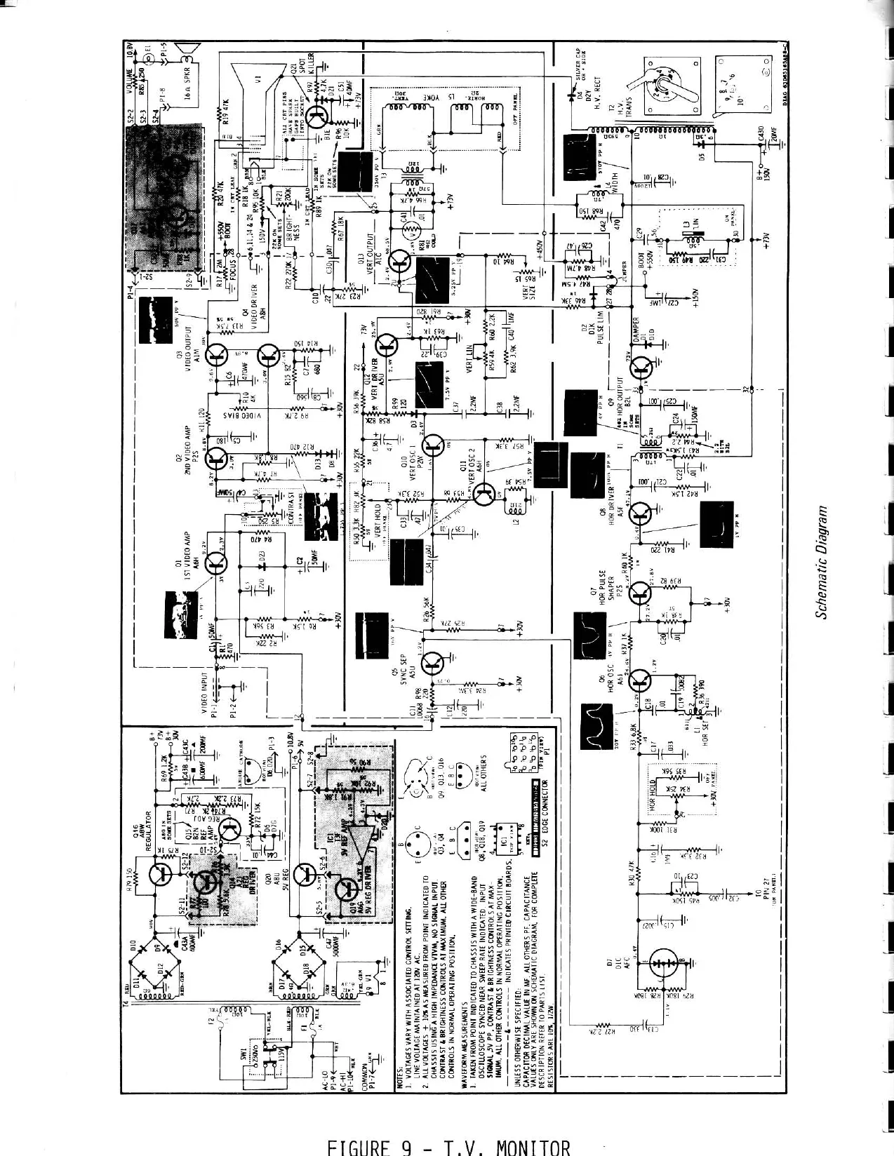
MONITOR
The monitor provides the video display of the signal from the logic
board. See Figure 9 for schematic.
SPEAKER
Provides the sound.
FLOURESCENT LIGHT
Provides header and general game illumination.
INCANDESCENT LIGHT ‘
Provides flash of light during the explosion.
INTERLOCK SWITCH
Disconnects AC power when the back door is removed.
COIN COUNTER
Counts the coins put in the game.
TROUBLE SHOOTING TECHNIQUES
The following diagrams are provided to assist in trouble shooting
the unit:
Figure 4 Rear View of Cabinet
Figure 5 Underview of Gun Control Panel
Figure 6 Logic Board
Figure 7 Interface Board
Figure 8 Power Supply
Make sure the power cord is plugged in the wall socket and the
interlock switch is ON. The interlock switch is on when it is fully
depressed -- this requires the back cover to maintain closure; or
when the switch is pulled fully out -- maintains self in this
position.
Check all four(4) fuses in the game -- the system power fuse located
on the transformer filter board and three(3) fuses mounted on the
T.V. monitor.
Check the brightness and contrast control on the monitor, and turn
them in the direction to give maximum brightness and contrast. Adjust
the Vertical and Horizontal Holds if necessary.
se ee ee ese ee ee Se ee Ss SS SE Ee
Disconnect P-7 and turn brightness and contrast up. Check to see
that screen lights up indicating the monitor is working properly.
If there is no sound associated with the game, check the volume
control located on the interface board. See Figure 7. Check the
+23V DC at (+)side of the 250uF capacitor directly below P-7.
Whenever the game malfunctions, the +5V, -5V and +12V DC supplies
should be checked. Use any standard voltmeter. The +5V can be
measured by using any two buss bars in rows three through seven.
The -5V can be measured from ground to S2-A. The +12Y can be
measured from ground to S3-A. Be careful not to short these
supplies when making measurements.
IN THE EVENT THE PROBLEM IS ASSOCIATED WITH THE LOGIC
OR INTERFACE BOARDS, RETURN BOTH BOARDS ALONG WITH THE
INTERCONNECTING CABLE FOR REPAIR,
(@) USING CARE NOT TO DAMAGE WIRING
HARNESS, REMOVE ‘GU ASSY." FROM SHIPPING POSITION BY LIFTING TO CLEAR CABINET.
REMOVE' WING NUTS'¢ WASHERS FROM
UIOEESIOE OF GUN! MTG BOARD REMOVE @ MAKE SURE WIRING HARNESS |S
CLEAZ AND POSITION 'GUN ASSY.’AS
SHOWN, WITH LEADING EDGE OF GUN MTG. BOARD UNDER LIP I) CABINET AND GEOOVE DOWN OVER TOP EDGE OF FRONT PANEL’, @ INSTALL WASHERS €'WING NUTS’ ON CARRIAGE BOLTS USING OPEN 'COIN DOOR! FOR ACCESS.
SECURLY !
CARRIAGE BOLT —
\ GUN ASSEMBLY GUM ASSEMBLY | (AS SHIPPED) (INSTALLED)
~CABINET~
UNPACKING AND SET-UP
OF GUN PANEL
FIGURE L
SC CABINGT ic =} WING SCREWS — ij SAVE) --REAR OF STEP
| SHIPPIIG & | HI | C | (AS SHIPPED) |
| cease
| Z OIA HOLES | 78) | sy | ay |
IM CABINET a l —— oT
| | | | | if | ||
| { | fine a | : | - | He |
IO" .
| wae we q eo ue SCRIBE MARK —
| STEP (EXTENDED) | _~ | ae Siar |
| CoM Roow — | TOP | VIEW |
(SECTION) TO EXTEND STEP: C) OPEL ‘con DOOR’ FoR Access. et
| @ REMOVE COIN BOX. | . | “LJ | | |
- REMOVE SHIPPING BLOCKS' FROM STEP.
@ PULL STEP OUT To TEN
(10") INCHES oR'SCRIBE MARK’, AS SHOWN,
- TO LOCK STEP iy
PLACE, INSTERT'WING
SCREWS’ THRU ¥%," FRONT VIEW DIA HOLES IN CABINET AND TIGHTEN,
PULL OUT SHELF
FIGURE be
ce ce JenvourpuT Gl Po ~ [ea-svoe 3) -5VDE _ v CB) EVDO CH +evoe () GND 6S) SND.
[ s) aio QD+EY URES COVES UNIRES oka
- +35v UNREG SO LNRES GHD | COrUNRES ENO | (S) GND
PS45UTSBVIONWR BIS Pe Pi O) GuN IK @) GUN @K ancrys oun on (B) GUN SA CIGUN 4K G) PYRE = IN 48 [oo -Ww unRee |
- GUN 35. @@) FIRE B encunie | ) Gun 5A | ©) coms (oO) START LEFT GUN
J 4a o e g es if
INTERFACE BOARD @2) oun 28
- SUK ZA eo«—«—v——_OOCO A) GUN A CD “NY UNRES G5) Gun 5B | 7) -1N unre |
- cow GND _@y TO. com Couns. | (or TT | (ABTS coms Coun,
Pw BOTS IONIZED Koo) Tut (S)_ GND kan Gun ie
© COIN los eun 38 a aad Gun 4 las) cum SB loc) FRE © Ko7) = UNRES.
CON COUNT] } CONN COUNT]
ES Nee 24 RIGHT GUN
ICI VIDEO GND. a (@NIDES OUT g
+5V 70 $5 REL
- WENT OUT (S)_ SPEAKER @) SPEAKER ey ] Ba on
Py 14 2eoNie
FIGURE 3 BLOCK DIAGRAM ko) WNR :G GND (OVUNE WS GD (2)435V UNRES OAV WWREG. ( 4NWV UN REG. Go) WY UNRES,
1246789 018 Jarrccom | cay Ke cova |
XFMR BOARD ASSEMBLY IS 1S 17 18 19 20 2! 22
wpuT INTERLOCK SWITCH
nS VAC SPE AKE} mR EXP! LOSION, LIGHT
~~ FLOURESCENT LAMP
INCANDESCENT BULB
LE fa ae TF a Z a
iL ae: | | _ I
1 C | me
A el a _-— INTERLOCK a _— 1 SHITCH
FUSES ——1— voLune | t HORTZONTAL Logic Se BORD = : VERTICLE a BRIGHT INTERFACE CONTRAST BOARD
TRANSFORMER ASSEMBLY
PEAR VIEW OF CARTNET
FIGURE 4
=] cH OC | \
A GUN ALIGNMENT : A | WITH GUNS APPROXIMATELY \ mmr ; Io PERPENDICULAR TO FRONT OF CONTROL PANEL AND AGAINST BUMPER STOP, ALIGN WIPER SWITCH MOUNTING PLATE SO THE OUTSIDE CONTACT IS APPROXIMATELY 1/16" FROM THE OUTSIDE PAD ON WIPER BOARD. THEN TIGHTEN CAP SCREW IN COLLAR (5/32 ALLEN WRENCH) .
WITH WIPER BOARD REMOVED, USE SPACER BLOCK TO SET WIPER BLADES 1/4" FROM CONTROL PANEL - CARE MUST BE TAKEN NOT TO INTERFERE WITH WIPER BLADE OR WIPER BLADE MOUNTING PLATE SETTING WHEN REINSTALLING WIPER BOARD.
\/ view A-A 4 (CARD REMOVED)
UNDERVIEW OF GUN CONTROL PANEL FIGURE 5 fl eh a a ee a ce Ey a ae -aaiaie ee [|
- ee SSS OS OTF EE eS EE LOGIC BOARD AS POSITIONED IN CARD CAGE
POWER CONNECTOR SIGNAL CONNECTOR
/ PROS 7 a
nf | ~ 4] ¢
w af (_ a
o fj] : a
© ] — [€PU8080] a
5 co \ _,
n 1
\-DIP SNITCH
LOGIC BOARD FIGURE 6 v e960 34 o\n roy oa WN du si HF \
5V REGULATOR SUB ASSEMBLY
i — | NOISE ADJUSTMENT ox (FACTORY
S SETTING)
S&S +5V ADJUSTMENT (FACTORY |____ SETTING) J
SOUND ADJUSTMENT
INTERFACE BOARD
FIGURE 7
TERMINAL STRI +23V & +12V RECTIFIER DIODES ; FUSE tT 3A SLO-SLO
/* & - SVOLT
- RECTIFIER
© TRANSFORMER
This page is a drawing, shown as the original scan.
This page reads as a drawing: its text was drawn rather than typeset, and comes out in fragments. See the original scan.
- }e— /00NS L_ PRESET TO COUNT © DURING EL 14 loli lzlslelslelzlelslel7ialolols Izi3 lel TL 71
I Le=J
AK ‘ ROW = eh SCREEN | access | REFRESH GG: VALID Sara)
TI i PL ome —
1 1 1 an
i ——#WR
LL yatip pata From 080 oe WE TO RAMS FER 2080 CYCLES WITH MEMORY WHEN THEY accor
E | pant No ee
UIST OF MATERIALS: [So NOT SCALE ORAWING SIGNATURES bate RAMTEK S541) T7MING DIAGRA. IS GAME BOARD [¥f-"19 Tz Some PWS NG. 55085! Sur or 8
This page reads as a drawing: its text was drawn rather than typeset, and comes out in fragments. See the original scan.
L128 (€P-i} ads7a4y sc r
2. =| x 4] 432. ‘ INTA: L ; + MEMRD. RST (SF-13) (cr)
SYNC(SE-8} PE! S511)
4+DZ, sours _3
-Et4 DESCRIPTION
TERIALS|
RAMTEK T@GIC_ DIAGRAM, GAME BD,| M- 719 SIGNATO nr WLESTED
This page reads as a drawing: its text was drawn rather than typeset, and comes out in fragments. See the original scan.
REVISIONS: oN) ee
LINE COUNTER
VBLANK
- #y SANK 7 #VBLANK
243) 415] 6 or dé 14 15 Is Leis iol, S36 cab lS “LP. ee oF oe 6 iValstilia ut L2 4 8 Lie U7 LK UB S06 #58 spa
VELENK 333
MYBLANK > LOAD (6 BIT VIDEO S/R SDIECIS LIDS, 5B3 'S 305, ¥H BUNK ==
CK 2. COMPOSITE = SYRIC 33! SRIZINTAL SYNC 3DS, E32 4HE32 4 roe L a iC
- 033 H SYN ale — ew 3C5,H BANK: e = ig >= YCOMPSYNG ,*AL
\ZRTKAL SYNC 322, ve.
303,16
POR
pur ~—s QI CLOCK TO 8080 JIL,
Piz 62 LLPCK TO 8080 JL, oe ee Ls ox | ShE, 545, S05 SMHE CLOCK . 4i2V
HW
RAMTEK
LEGIC DIAGRAM, GAME BD,
f7s
GAME SWITCH INPUTS
- IAN77 en Foe \ 53 #107 a; wal Ges
INTS
{75 1b ge 4 tie 13| 34
C@rETO >
Fl- 7
Pee
Es IN __| as 7 x psaT7 = EKcADIS 2
cee | Ine LTE 5 pros Gi | a rz Ne 4 EN 4102 5 | 36
Pl-} t— cS @ | ole pe #101 i GED INGO. -. 4 CPI-78) fos i [ajar #100 | zs, PORT © 2A3OI~ 4 scented 244 J eacre ADDRESS 8006 jus * x By
SS SHT «
ADDRESS 8005
30 3__¥I07 >
10S ie pervs © Fi Gs #105
[stn suT2 TOE 3 [oe pis 105~\ @ (‘Se po #102 [iv pee = INdO 12 Gem —— AR #4100 zs, ¥rorraq ‘i 205 #ReAolt 3 PEADPS ADDRESS 8004 SHUT 2?
a
2 16 sa 2cS, #PgRTO—dz ds 9_! 4B @L5, #wkITIO ADDRESS E¢
Li
al 4 4! S
V
75, 20S, 4 3C2. VAL SHT?
rE
205, ppoer2 “gaa 25, #renvid 12 $4
REVISIONS
i
GAME PULSE QUTPUTS GAME STATIC QUTPUTS
¥107. ——t. SOUND CONTEOL 302 | eu SES ese 74
| t1DG | mea 4 pets€7 | \ | #4053401 | Q| 2idurie |
~
| ) | i | #10441 v2 | ni Siem |
| — | #103 Il pz | Q 7 €4uTIO |
SMT ppp "| og 44 KGuT9 P
| By | #10) 3 os | of 242UT8 | ES, |
| i | #100 41 p6 | gseaur7 | easy | "3 |
CK =
| #1D3 | 2 | 17 | ad |
paz ¥ POR, 307
| «1D? — fe) 4 PULSER | | | LD PRTZ |
G\3amM i
| - | , | rs | 2¢5,8Pder2 2h 502~ 104 | ||
| «pi | Fol 0 puisez | 4 | welt | S| 3? | » |
| ; | lod se \ 10 FLLSEZ | : | 205, #wRITIG | ||
| - | 7 | , 3 | ADDRESS 8002 | ||
| #00, | 4302 13 purse! | | |
(4 3 fone ai
| swe | irene | , |
isl za Yo-#107 >) rs ps3
| SW? | 3 | = | #105 3_| ol | a |
| Dol co ye #106 | 1044 loz | 4 | ||
| _ | surg J #03 2403 | Qa | ||
| cy Y2-#105 | #02 14 D4 | Q |
#10! 3 | 95 4a @
| 8 | ' | CoN | “ylo | 3N |
| z | 2] en Ye-#04 | #1004 1D6 | @ |
$24
| i | SHTZ | 21K. | |||
| a | G | sw4 | 9 | > | R | |
| fife {e | 10 | Cp | pe #103 | 7 | SELF TEST | |
| 6G | 2 | #70R,307 | "1"= TURN EN LED | ||
| ‘ | 4 | tN | ane | (SELF TEST FAIL? | |
| 3 sw3 | ISiGS | a | LOPRT3 | 0" = TURN OFF LED | |
| 2 sw2 | 1 | 2 | : | . | |
| fies. | 2 | 273 | NOTE: | ||
| een | baler }=-#0! | 205, #edars ~* 508 | POWER dy FESET GR, RESETSWITCH | ||
| r | sw | 4 | 205, wRITIP | q | Wilt TURN OA pes i |
105 G "OQ WILL TURN IEF FAIL T@ INDICATE
| 5 [oF ye 4100 J | ; | ADDRESS 8003 | PASSING CONDITION. |
s, ep spesnid Sd 6 Jreaprep ADDFESS 8000 tig = [a7 pt +100
ITEM SeSCRIPTION Uist OF MATERIALS
RAMTEK @aiC DIAGKAM, GAME BD, M-79 Se Peano vs! 950851 cers a aa
REFRESH] 8080 ADDRESS SELECT
ADH Tale 663 TAU ADDRESS? iyo & BIT ADDRESS 1/2 A? SELECT (elze, lt REFRESH 4, J cea it ADDRESS uz 5] ae aml KADDS (ens) cv RADDS
(tHe 8080 aord Taz | ADDRESS * the H (tas ( ts REFRESH... | ta apps 1 ADDRESS *°~ ie os L a FADD |sintieve (sps) cyeoeo . i _sabee Lr = 4A SIG : i (144 cee 1134 7R h ; 080 40, J 103 Lot ADDRESS") 122 (2 (TAL 3 ( £128 = REFRESH. £64 ADDRESS*”°* 32 8 |24
(Gps) Cveoso >
383, CK7
EN BYTE ODD EYTE
| DRESSES | ; | SELECT | “area | = |
7 ADDRESSES S020 |NTERNAL DATA BUS SPard FAIS Eig 1a PAIAIZ RAM 12 KEMT RAG 1 | kAMS _&
| Rama ya, z | epaTd | 2 |
71 Ve O8N 2 #1 TAO ——— e420 dT Dar a 2 eam Bigg [te [alo? Ul xIDS RAM{o 10 }38 él, Rama —2\2B 7 RDATZ 9 37 iC: xamea 3.18 6/6 fol ee x8. 4102 | gam3 4 |aa 4 |? ”
| game _Ll3a 7H | EPATI | SEN. 6 ap? |
gami Slea 14 Aas ramo 2 lia sa EN 3 yep
| 2104 [2 m4 | 2_ pra | mo | —] }s | 23 |
BE |i4 2 rs) id L/4 gama = EN {i eamiz ebb, #FFG2080 ~ 2DS, #kEAD MEM areas 7 7104 | PIs 704 [2 283 BD [4 pam3 RAMI
7104 |e Pre BC |4_ game DIZ
RAMIO
2 Dl
i RAMI
|04 }2— pro BA |i4 pamo
UST OF MATERIALS
RAMTEK » LOGIC DIAGKAM,GAME BP, M-79 ats FAT $5085! len NOT ScaLE DRawing] SIGNATURES
This page reads as a drawing: its text was drawn rather than typeset, and comes out in fragments. See the original scan.
TES OPERATION
RAM
! aw
UMN ADDKESS STROBE 7 [2 p34 _88._ sans, 22 Cc
Ril
“S22)
VRITE ENABLE " 2, a> z ito yo FAS Lee AS, $8
<2) 2C7,1AO sey) 7¢7, 6K + Zn oN, tt *WEO, S87 (LOW BYTE)
This page reads as a drawing: its text was drawn rather than typeset, and comes out in fragments. See the original scan.
This page reads as a drawing: its text was drawn rather than typeset, and comes out in fragments. See the original scan.
This page reads as a drawing: its text was drawn rather than typeset, and comes out in fragments. See the original scan.
This page reads as a drawing: its text was drawn rather than typeset, and comes out in fragments. See the original scan.
This page reads as a drawing: its text was drawn rather than typeset, and comes out in fragments. See the original scan.
ci DESSmIPTION PROTO REV PER ECO 307439 wl
P/o
LIGHT #L INPUT
NOTES: UNLESS OTHERWISE SPECIFIED ND a 1. ALL RESISTANCE VALUES IN OHMS, I4WE5%.
- ALL CAPACITANCE VALUES IN MICROFARADS. f
3 REF DWGS5. FAB DWG 5503855 Cc ASSY DWG 550856
Tt -IIV UNREG +5V
cR5 cot Cod IN4O01 | 1.0 39 B lov
i
ITEM DESCRIPTION LIST OF MATERIALS 7 oO ROT SCALE a RAMTEK SIGNATURES — [DaTE SCHEMATIC DIAGRAM— INTER FACE wo NO. Rev Diene2| 350854 1B TOLERANCES
we Dwr | aE crs ye Meyute
IN@1S4 ‘ ace i Plo PA + 35V,
UNREGULATED
MC REV
INPUT
C37, 500 PF 1t F (latao C2av) id 14 Vv, N47. 42av
M,C, CONTROL
WHISTLE
“apa [23
s'wrut (24 WB ahs SIGNATURES loo NOT SCALE DRAWING|
ck =) RAMTEK SCHEMATIC DIAGRAM INTERFACE 550854 |B UIST OF MATERIALS ITEM DESCRIETION Treas zac] 4-1 ee \ov = Plo PT I sPeawer
| Tar *47 4700 470eRT.
"Tt He eas 2N3055 &
a-_ n
UNREGULATED
+IVGG To LUGHTS PA +i
\NPUT +5V0C OUTPUT GO OUTPUT
GNO OUTPAT
GND OUTPUT
TiN UNREG
HEATSINK, ulo Ta\2 ra +1OV UNREG t+12voc OUTPUT UNREG GNO UNREG GND -S5V0OC OUTPUT REVISIONS
This page reads as a drawing: its text was drawn rather than typeset, and comes out in fragments. See the original scan.
LOIN DICOR
COINS OUNTER
- SPEAKER (2)_ SPEAKER.
SPEAKER
@) VIDEO WUT [eacnor | @) Ae com
Lay) MAG RELAY ©) Guid ) GND UNREG, (BY GND UNREG WV ANREG | COUNRES GUD Qa35v UNRES SDHoV WREG, kon URES GND. CRS E «@) wy EXPLOSION. LIGHT
ri
g
7? g
INTERLOCK SWITCH
y i Ll 2 OF J AR : “) ap Ft Or i glad] el 38 =| €] | 8} 6] s\ 6 24 @ 7 BF 10M 1B 14 15 te 17 1B 9 20 2 22
XFMR BOARD ASSEMBLY WS VAC WPLT,
ITEM DESCRIPTION
TOLERANCES RAMTEK Dare Sct ff L079 Aimeese 7277 Etock OUCKAA ize SIGNATURES Own] Ko GASEIS Gener.