Mortal Kombat 4 25in Dedicated (16-40061-101 Final Sep 1997)
Mortal Kombat 4 (version 3.0) (Midway, 1997) · Manual · 55 pages · 46 sections · original scan
September 1997 MIDWAY 16-40061-101 FINAL
aiiatertoemael
OPERATION MANUAL
FOR 25” DEDICATED GAME Operation & Adjustments * Testing & Problem Diagnosis
Parts Information ¢ Wiring Diagrams
MIDWAY GAMES INC. 3401 NORTH CALIFORNIA AVENUE CHICAGO, ILLINOIS 60618
If a dollar bill validator is desired, the Mars up-stacker AE2411 is recommended.
DECLARATION OF CONFORMITY
MIDWAY GAMES INC.
3401 N. CALIFORNIA AVE. CHICAGO, IL 60618 U.S.A.
WE, HEREBY DECLARE UNDER SOLE RESPONSIBILITY THAT
THE MODEL: "MORTAL KOMBAT 4" - 25" 40261,40361,40461,40761, 40961,41061, 41461,41861, 42061,42261,42361, 46561 (VIDEO) TO WHICH THIS DECLARATION RELATES IS IN CONFORMITY WITH THE
FOLLOWING EUROPEAN PRODUCT SAFETY DIRECTIVES:
ELECTROMAGNETIC COMPATABILITY DIRECTIVE (89/336/EEC AND AMENDMENTS 91/C162/08, 92/31/EEC,93/68/EEC
ELECTRICAL EQUIPMENT DESIGNED FOR USE WITHIN
CERTAIN VOLTAGE LIMITS DIRECTIVE (73/336/EEC AND AMENDMENTS 88/C 168/02, 92/C210/01, 93/68/EEC,94/C199/03, 95/C214/02)
AS IS VERIFIED BY COMPLIANCE WITH THE FOLLOWING STANDARDS:
ENS55014: 1993 EN61000-4-2: 1995 IEC 801-3: 1984 (EN61000-4-3) EN61000-4-4: 1995 EN61000-4-5: 1995 EN60065: 1993
Date issued: AUGUST 7, 1997
DAN GALARDE
CORPORATE V.P. OF QUALITY
MORTAL KOMBAT
Dedicated 25” Game
If a dollar bill validator is desired, the Mars up-stacker AE2411 is recommended.
The information in this manual is current at time of its release.
Fill out and mail in the game Registration card. Be sure to include the game serial number. For your records, write the game serial in the manual.
Serial Number.
MIDWAY Games Inc. reserves the rights to make modifications and improvements to its products. The specifications and parts identified in this manual are subject to change without notice.
TABLE OF CONTENTS Section One - Operation and Troubleshooting Safety Notices. Set-up Procedure. Inspection at Location Requirements... Cabinet Assembly Diagrams. Servicing... Game Features.
Control Panel Diagram. Game Operation... Control Switche: Control Switch Location Menu System Operatio! Operation. Main Menu..
DIP Switch Table and Test System Test and Sound Test Monitor Patterns. Burn-in Test ... Mechanical Counter Test. Coin Bookkeeping. Game Audits... Game Adjustments..
Volume Adjust...
Section Two - Parts Information Cabinet Front - View 1 Cabinet Front - View 2 Cabinet Rear View. Rear Door Parts. Pushbutton, Joystick Detail Control Panel & Housing Parts.. Coin Door Parts Power Supply. CPU Board. Other Parts Necessary. Line Cord Application Chart, Coin Door Chart.
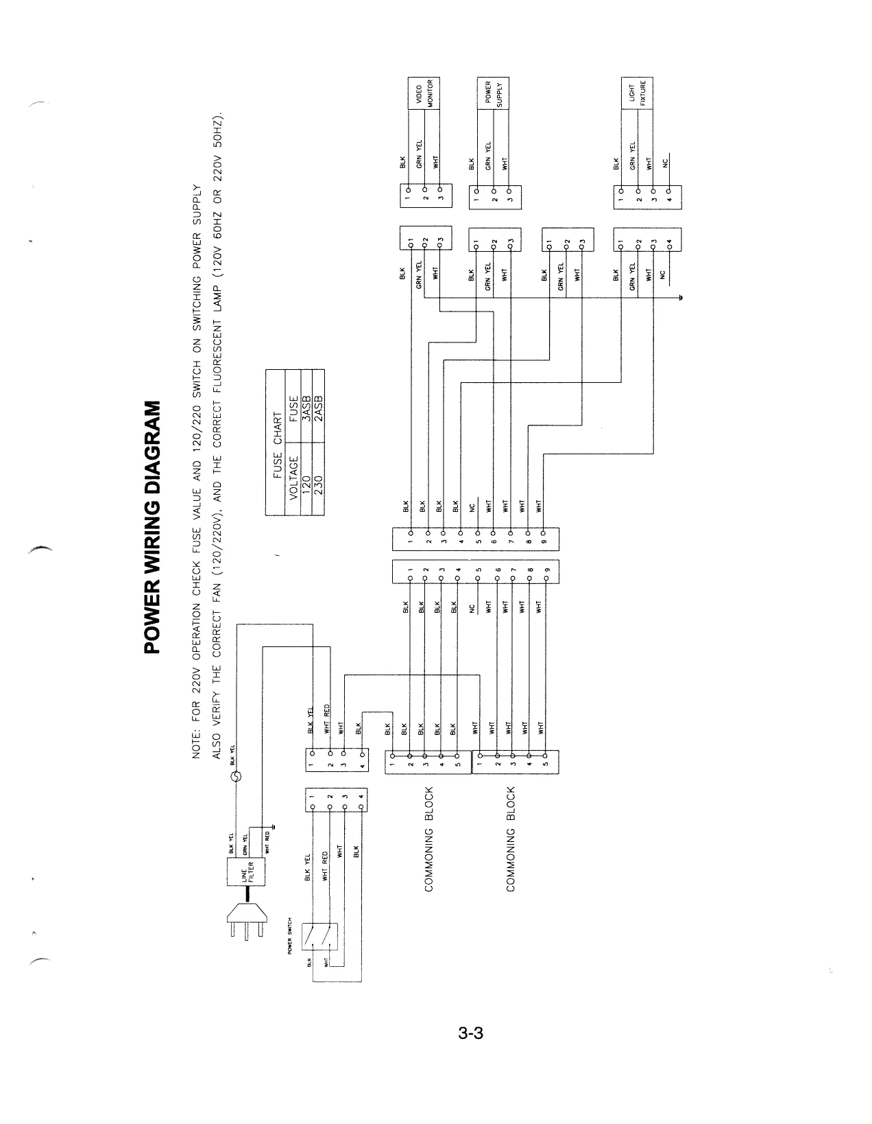
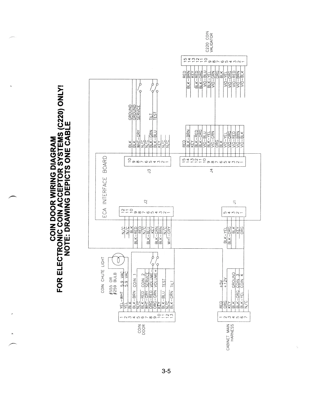
Section Three - Cabinet Wiring JAMMA Chart. Power Wiring. Cabinet Wiring Diagram. Coin Door Wiring for Elect ptor Sy: Section Four - Troubleshooting Game Appears Completely Non-functional Marquee Lamp is Non-functional. Monitor Appears Non-functional. Sound is Non-functional. Video Game Appears Non-functional. The Video Screen Exhibits Loss of Sync or Horizontal Tearing. The Audio Sounds Distorted, Muffled, or Missing Frequencies... The Game Enters Power-on Diagnostics, But Doesn't Enter Normal Game Pla\
© Copyright 1997 MIDWAY GAMES INC.
MORTAL KOMBAT
Dedicated 25” Game
SECTION
ONE
OPERATION
SAFETY NOTICES The following safety instructions apply to all game operators and service personnel. Specific warnings and cautions will be found throughout this manual where they apply. We recommend that you read this page before preparing your game for play. ZN CAUTION
HANDLING ELECTRONIC DEVICES: This product uses complex electronic components that are SENSITIVE to static electricity. The following precautions must be observed and followed prior to handling any of the electronics that make up this game.
- Discharge any static electricity build up in your body by touching the safety ground stud of the power supply chassis. This is to be done PRIOR to touching or handling the electronic assemblies.
- Store the electronic assemblies in an anti-static area. Anti-static bags are to be used to store the CPU assembly.
- DO NOT remove or connect any electronic assemblies when the cabinet power is turned on. Doing so will damage the electronic assemblies and void the warranty.
TRANSPORTING GAME: This game contains fragile electronic devices. Do not move this game with power turned on. Transport this game securely. Avoid rough handling.
ISOLATION TRANSFORMER: This video game system does not utilize an isolation transformer. No isolation exists between the cabinet AC system and the external AC line.
PROPERLY GROUND THE GAME: To avoid electrical shocks, do not plug in the game until it has been inspected and properly grounded. MIDWAY games should only be plugged into a grounded 3-wire outlet.
DISCONNECT POWER DURING REPAIRS: To avoid electrical shock, disconnect the game from the AC. power source before removing or repairing any part of the game.
USE THE PROPER FUSE: To avoid electrical shock, the replacement fuse must match the original fuse in fuse type, voltage rating, and current rating.
HANDLE FLUORESCENT TUBE AND CRT WITH CARE. If you drop a fluorescent tube or CRT and it breaks, it will implode! Shattered glass can fly eight feet or more from the implosion.
EPILEPSY WARNING A very small portion of the population has a condition which may cause them to experience epileptic seizures or have momentary loss of consciousness when viewing certain kinds of flashing lights or patterns that are present in our daily environment. These persons may experience seizures while watching some kinds of television pictures or playing certain video games. People who have not had any previous seizures may nonetheless have an undetected epileptic condition.
If you or anyone in your family has experienced symptoms linked to an epileptic condition (e.g. seizures or loss of awareness), immediately consult your physician before using any video games.
We recommend that parents observe their children while they play video games. If you or your child experience the following symptoms: dizziness, altered vision, eye or muscle twitching, involuntary movements, loss of awareness, disorientation, or convulsions, DISCONTINUE USE IMMEDIATELY and consult your physician.
ATTENTION PROPERLY ATTACH ALL CONNECTORS. Be sure that the connectors on each printed circuit board (PCB) are properly connected. If they do not slip on easily, do not force them. A reversed connector may damage your game and void the warranty._All connectors are keyed to fit specific pins on each board.
SETUP PROCEDURE
Game Location Requirements
Power Temperature Humidity
Domestic 120VAC @ 60Hz 3.0 Amps 32°F to 100°F Not to exceed 95% relative Foreign 230VAC @ 50Hz 2.0 Amps (0°C to 38°C) Japan 100VAC @ 50Hz 3.0 Amps
Cabinet Statistics Shipping Dimensions Shipping Weight Width 27" - Depth 41" - Height 73" Approx. 335 Lbs
INSTALLATION & INSPECTION
- Remove all items from the shipping containers and set them aside. Inspect the exterior of the cabinet and the control panel for any damage.
- The coin door keys are attached to one of the joysticks. Unlock and open the coin door and the cash box door. Remove the spare parts stored in the cash box.
- The rear door keys are located on a key hook inside the cabinet, to the left of the coin door. Remove the screws holding the rear door then unlock and remove the door. Inspect the cabinet interior for any signs of damage. Check all major assemblies to assure that they are mounted securely.
- Refer to the Cabinet Wiring Diagram (Section 3), and check to see that all cable connectors are correctly secured. Do not force connectors. Watch for damaged connectors and avoid making reversed connections.
- Unscrew the Monitor Controls board from the inside left wall of the cabinet. Stick it onto the Velcro strip located on a wood beam under the front of the monitor.
- To secure the rear door with a padlock, remove the two nuts from inside the cabinet, above the rear door opening, leave the bolts in place. Remove the hasp from the spare parts bag. Slide the hasp on the bolts so that it protrudes from the hole in back of the cabinet. Replace the nuts.
Remove the two nuts and bolts from the back of the rear door, holding the lock plate in place. Turn the lock around so that the slot in the plate is below the door. Reinstall the two nuts and bolts.
- Next, locate the four leg levelers among the spare parts in the cash box. There are four threaded holes on the bottom of the cabinet, one in each corner. Place one leg leveler (with its hex nut) in each of the threaded holes. Lower each leg leveler until the cabinet is stable and level.
10. To attach the line cord, remove the four Phillips-head screws that mount the line cord cover plate to the rear of the cabinet. Match the prongs on the plug with the holes in the receptacle and push the line cord securely into place. Be sure the cord aligns with the indentation of the plate, (indentation should point toward the bottom of the cabinet). Remount the line cord cover plate.
(Part of cabinet shown for reference only) _, Phillips—head Screw Receptacie
Line Cord & Plug
Tamper-resistont Screw
Replace the rear door and fasten securely to the cabinet using the four HWH screws. Lock the rear door and remove the key.
IF TAMPER RESISTANT REAR DOOR SCREWS ARE DESIRED, tamper resistant screws and matching wrench is provided with the game. The tamper resistant screws and wrench are located in the spare parts bag. Replace the HWH screws with the tamper resistant screws and tighten the screws with the T20 Torx wrench provided.
Move the cabinet to the desired area. Be sure it is level. Verify that the AC line voltage matches the game requirements. Plug the game into a grounded (3-terminal) AC wall outlet. Switch ON the game, using the ON/OFF switch located on the upper left rear of the cabinet. The game should begin the Start-up tests and then enter the Attract mode.
CABINET ASSEMBLY Front View FLUORESCENT BULB
JOYSTICK:
BUTTONS S
COIN DOOR cS ©
CASH 80x DOOR =
Rear View
vent cover 3)
CPU/SOUND BOARD. - SWITCHER POWER SUPPLY
1-5
SERVICING
@ Removal of the Marquee Switch off power to the game. Remove the hex-head screws from the black marquee retaining strip located on top of the header. Remove the strip and carefully lift the marquee and the marquee glass from the top of the header. Store the marquee carefully to prevent damage.
@ Removal of the Fluorescent Light Assembly Switch off power to the game. Remove the marquee glass and the marquee. The fluorescent bulb is now accessible for replacement. Remove the plastic lamp locks. Grasp the bulb, give it a quarter turn, and remove it from its socket. Carefully, place a new bulb into the socket, and turn to reinstall.
To remove the entire light fixture, disconnect the fluorescent light assembly from its power cable. Remove the screws that hold the assembly to the cabinet then lift out the assembly.
@ Removal of the Speakers Switch off power to the game. Remove the marquee and the marquee glass. The speakers come out from the front of the cabinet. Be sure to disconnect the cabling and remove the nuts on the mounting screws before attempting to remove the speakers from the enclosure. Carefully, reinstall the seals upon completing any task in the speaker enclosure.
@ Servicing the Control Panel Switch off power to the game and open the coin door. The control panel is held in place by two latches (located inside the cabinet) which provide constant pressure on the strikes. To release the latches, reach through the coin door opening toward the right and left sides of the cabinet. Lift the latch handle and unhook the wire fasteners. Grip the joysticks and carefully tilt the control panel back on its hinge.
To return the control panel to its normal position, carefully lean it forward until it rests on the cabinet. Be careful not to let the control panel slam down onto the cabinet, or to pinch any wires. Always reclasp the latches.
@ Removal of the Viewing Glass Switch off power to the game and open the control panel. Loosen the three Phillips head screws and slide the black metal strip from the bottom of the viewing glass. Carefully slide the glass from the side grooves and lift it clear of the cabinet.
¢@ Removal of the Monitor Bezel Switch off power to the game. Open the control panel and remove the viewing glass. Lift the bezel off of the monitor.
@ Monitor Replacement We recommend that you read the SAFETY NOTICES section thoroughly before beginning this procedure.
Switch off power to the game. Remove the viewing glass and the monitor bezel. Completely disconnect the monitor from all of its cabling. Remove the four flange nuts securing the monitor's mounting flanges to its mounting panel. Pull the monitor carefully from the cabinet.
AN CAUTION
The monitor does not require an isolation transformer. However, when servicing the monitor on a test bench, YOU MUST ISOLATE THE MONITOR FROM LINE VOLTAGE WITH AN ISOLATION TRANSFORMER. THE MONITOR IS HEAVY. BE SURE IT IS FIRMLY SUPPORTED IF IT MUST BE REMOVED FROM THE CABINET.
# Volume Control, Begin Test Switch, and Service Credit Switch Open the coin door. The game's volume control and diagnostic push-button switches are located on a small bracket on the coin door. The two center buttons controls the volume. Press the Volume Up or the Volume Down button until the desired sound level is reached. The Begin Test switch, on the right, activates the game's menu system. The Service Credit switch, on the left, allows credits to be allotted for service testing without affecting the game's bookkeeping total.
CONTROL SWITCH LOCATIONS seruce vouwe Down vowuwe cReoS ta B0n mest
SLAM TILT x
1-7
GAME FEATURES
STARTING UP Switch on the power and the game begins the Start-up tests. Several colors scroll across the screen, after which the System test begins and a “tone”, indicating that the sound circuits are operating, plays. After the Start-up tests have been successfully completed, the game enters the Attract mode.
Insert the desired amount of coins, bills or tokens. Select which player receives the credit by pressing the appropriate Start button. Use the joysticks to select an on-screen character, and any control panel button to confirm your choice. Game play starts automatically once the on-screen characters are chosen.
PLAYER CONTROLS ° Start Button Each player has a Start button. The Start buttons allow one or two players to begin or continue play.
Joysticks Each player has a joystick, which he uses to control an on-screen character. The player can make the on-screen character move, jump or duck.
High Kick/High Punch Buttons These buttons allow the on-screen character to kick or punch an opponent in the upper body.
Low Kick/Low Punch Buttons These buttons allow the on-screen character to kick or punch an opponent in the lower body.
Block Buttons These buttons allow the on-screen character to block an opponent's punch, kick, or special move.
Run Buttons These buttons speed up the on-screen character.
START (WHITE) START (WHITE)
vowe June rp | Fup WIGH PUNCH HIGH KICK (Re0) (eive) Move Move (@) Lock HIGH PUNCH HIGH KICK (RED) (@Lue) 7 Oso i
oucK (REO) (BLUE) buck (RED) (BLUE)
(reL08") (reLtow) |
Control Panel
GAME OPERATION The MORTAL KOMBAT 4 Control switches are located on a bracket, inside the coin door.
CONTROL SWITCHES
@ Slam Tilt Switch The Slam Tilt switch prevents pounding for free games. The coin switches are ignored for five seconds after the Slam Tilt switch is closed.
¢ Volume Down/Volume Up Buttons The Volume Down and Volume Up push-button switches increase or decrease the volume level of the music and speech. The volume level can be adjusted during the Attract Mode or during menu system operation. For greater profits, set your game's volume level at a nice loud setting.
+ Begin Test Button The Begin Test push-button switch enters the game's menu system. Press the Begin Test switch to access any of the menu system functions.
¢ Service Credit Button The Service Credit push-button switch is a special feature switch that allots credit without affecting the game's bookkeeping total.
| ‘service | VOLUME | VOLUME. == «BEGIN | |
| eReoS | WN | ve | rest |
O_O OO
| scare | © | &) | a |
SLAM TILT
Control Panel Switch Locations
MENU SYSTEM OPERATION
OPERATION All of the game audits, adjustments, and diagnostics are options of the Main Menu. Each option, in turn has its own menu that lists several choices that you may act upon as desired.
Press the Begin Test switch on the coin door to open the Main Menu (shown below). Game adjustments, bookkeeping and diagnostics are all accessible from this menu.
Use either joystick to move the cursor up and down the menu screen. Notice that the options are highlighted in sequence. Press any button on the control panel to open a highlighted option.
Mortal Kombat 4 Test Menu Game Code Version XXXX (compiled X/XX/97)
Diagnostic Tests Coin Bookkeeping (Monitor Patterns Game Audits Game Adjustments Burn-in Test
Utilities Coin Counter Test
System Info Return to Main Menu Volume Adjustment Exit to Game Over
MAIN MENU SCREEN
To exit the Main Menu and return to the Attract mode, use either joystick to select EXIT TO GAME OVER and press any button.
DIAGNOSTIC TESTS Use either joystick to select the Diagnostic Menu and any button to open it. Then, use either joystick to move the cursor up and down the menu and any button to open a highlighted option.
To exit the Diagnostic Menu, use either joystick to select RETURN TO MAIN MENU and press any button.
Scroll with Joystick Select with any Button
Switch t DIP Switch Test System Test Sound Test Monitor Patterns Burn-in Test Coin Counter Test Return to Main Menu
DIAGNOSTIC MENU
Switch Test The Switch Test allows the operator to test the switches on the control panel and in the coin door.
Use either joystick to highlight the Switch Test and any button to begin the test.
During the Switch Test the top of the screen shows the control panel switches while the bottom of the screen shows the coin door switches. Press a control panel or coin door switch and the switch location on the screen lights. Release the switch and the screen reverts to normal.
To exit the Switch Test, press both Start buttons together.
| . | ‘4 | OS 0650 | . | ‘ | x 6" So |
PrP P88
| O Coin 1 | O Coin 2 | (@) Coin 3 | O Coin 4 |
| O Vol + | (@) Vol - | oO Bills | (@) Door |
oO Credit Orit Oservice
Press Both Start Buttons to E:
DIP Switch Test The DIP Switch Test allows the operator to check or change the position of the DIP Switches on the CPU Board.
Use either joystick to select the DIP Switch Test. Press any button to access the DIP Switch Setting Tables. The screen displays the current settings. To change a setting, slide the switch to the desired position. Check the screen to verify the new setting. In some cases, setting a function to OFF actually enables the function. For example, setting DIP Switch Coinage to Off enables DIP Switch Coinage.
Press any button to return to the Diagnostic Menu.
DIP Switch 1 Setting Table sw. I sw.2 [Ssw.3 |[Sw.4 [Sw.5 |Sw.6 | Sw.7 |Sw.s | Fatalities Don’t Show Off* Show On Blood In Game Don’t Show Off* Show On Not Used Off On Not Used Off" On Not Used Off" On Not Used Off" On Not Used Off" On Not Used Off* On
Table SW.7 | SW.8 DIP Switch 2 Settin: sw.1 | sw. 3 | Coinage DIP Switch Off*
CMOS, On
Coin Settings
| USA 1 | Ger. 1 | Fr. |
| USA 2 | Ger. 2 | Fr.2 |
| USA 3. | Ger. 3 | Fr.3 |
El
| USA4 | Ger. | Fr4 |
| USAECA | Ger.ECA | Fr. ECA |
| USAQ | N/U | N/U |
| USA 11 | N/U | N/U |
| Free Play | Free Play | Free Pla) |
Country USA Germany
Off* Off*
On Off
France Off On
Not Used On On Not Used Off* On Test Switch Game Mode Off" Test Mode On
- Indicates factory setting.
System Test The System Test allows the operator to monitor the functions of the CPU board. Select this test with any joystick. Press any button to start the test.
System Test (Hit any button to exit.)
Time Date PIC PIC N/U RAM Clock Wave RAM Bank 1 Wave RAM Bank 0 Fast RAM CMOS Memory Display INT Zeus Chip Sound System Hit Any Button to Continue
SYSTEM TEST MENU
Sound Test This test allows the operator to listen to some of the sounds this game is capable of producing.
Use either joystick to select the test, then press any button to open the menu. The screen displays two test options. Use either joystick to select an option and any button to begin the test.
Scroll with Joystick Select with any Button
Sound System Play Sounds Return to Diags Menu
SOUND TEST MENU
Once the test is completed, select RETURN TO DIAGNOSTIC MENU and press any button.
Monitor Patterns The Monitor Patterns Test provides a menu for testing the monitor.
Select the test with either joystick. Press any button to open the test menu. Once the menu is open, use either joystick to select an option, and any button to begin it. Press any button again to return to the Monitor Patterns Menu. If any of the tests show a need for adjustment, use the proper knobs on the Monitor Controls board. The Monitor Controls board is located just inside the control panel opening, beneath the monitor.
Scroll with Joystick Select with any Button
Green Screen Blue Screen Color Bars Gray Scale Sizing Patterns Return to Diags Menu
MONITOR PATTERNS MENU
The RED, GREEN and BLUE SCREEN tests fill the screen with red, green or blue. Press any button to return to the Monitor Patterns Menu.
The COLOR BARS test fills the screen with 31shades of colors to help with red, green and blue level adjustments. Each color should appear sharp and clear. Press any button to return to the Monitor Patterns Menu.
The GRAY SCALE fills the screen with several shades of gray. Each shade should appear sharp and clear. Press any button to return to the Monitors Patterns Menu.
The SIZING PATTERNS test fills the screen with a grid and a series of dots. The grid and the dots should be clear. The dots should be round. Press any button to return to the Monitor Patterns Menu.
To exit this test, use either joystick to select RETURN TO DIAGNOSTIC MENU, and then press any button.
Burn-in Test The Burn-in Test will continuously exercise the appropriate sections of the game CPU.
Use any joystick to select the test, then press any action button to activate it. When the Burn-in Test detects an error, a message is displayed on the screen.
Burn-in Test (Press and hold any button to exit.) Total Cycles Completed: 1
E
Description Status
OK OK OK OK CMOS Memory OK Display INT OK Zeus Chip OK Sound System OK Wave RAM OK PQOL LOO 2S
BURN-IN TEST SCREEN
Once the test list is completed, the game begins playing sounds while the screen scrolls through several colors. Then the game displays the monitor tests: the color bars, the color screens and the sizing patterns. After completing the monitor portion, the test returns to the list display and the sequence starts over again.
Mechanical Counter Test The Coin Counter Test checks the function of the coin counters.
Use any joystick to select the test, then press any action button to activate it.
Joystick left/right selects meter. Press any button to click selected meter. Hit START to exit.
METER 1 METER 2 METER 3 METER 4
MECHANICAL COUNTER TEST MENU
COIN BOOKKEEPING The Coin Bookkeeping Table records the coin box totals and the game play counters.
Use either joystick to select the Coin Bookkeeping Menu, then press any button to open it.
Coin Bookkeeping
Left Slot Coins. Right Slot Coins. Center Slot Coin: Fourth Slot Coins.. Bill Validator Counts. Paid Credits.. Service Credits. Total Plays... eooooo0oco
R fa} 2. ° Total Collections...
Hit Any Button to Continue
COIN BOOKKEEPING
To exit Coin Bookkeeping simply, press any button.
GAME AUDITS Use any joystick to select the Audits Menu, then press any action button to open it. Page through the available audits by selecting NEXT PAGE or PREVIOUS PAGE.
Game audits cannot be set. They can only be cleared.
Scroll with Joystick Select with any Button
AUDITS MENU SCREEN
Display Audit Data
Scorpion Chosen Raiden Chosen Sonya Chosen Liu Kang Chosen Subzero Chosen Windgod Chosen Shinnok Chosen Noob Sailbot Chosen Quan Chi Chosen Tanya Chosen Maki Chosen Reptile Chosen oeoooocoooo0o000o
Next Page Previous Page
PAGE 1 OF AUDIT TABLE
Display Audit Data
Hours Game Was On Oo Hours Played With 1 Player Oo Hours Played With 2 Players (0) Total Plays (0) 1 Player Continues Taken 0 2 Player Continues Taken 0 Burn-in Loops Successfully Completed
Next Page Previous Page
PAGE 2 OF AUDIT TABLE
1-17
GAME ADJUSTMENTS The Game Adjustments allow the operator to customize the game.
Use either joystick to select the Game Adjustments Menu. Press any button to open the menu.
The Game Adjustments Menu offers several options. Each option has several choices. Use either joystick to select an option, then press any button to open the option. The next menu screen provides a setting value. Use either joystick to change the setting value and press any button to lock it in.
To exit the Adjustments Menu, use either joystick to select RETURN TO MAIN MENU, and press any button.
Scroll with Joystick Select with any Button
Mechanical Counters Bill Validator Free Play Game Difficulty Fatalities Attract Mode Sounds Return to Main Menu
ADJUSTMENTS MENU SCREEN
Standard Pricing Standard pricing allows the operator to choose any of the “standard” selections from the Standard Pricing Table.
Select Standard Pricing Mode
Move joystick up/down to select pricing mode. Hit any button to accept.
1 of 61 Pricing Mode: USA 1 2 to Start, 2 to Continue 1 CREDIT/1 COIN
Left Chute: Right Chute: Center Chute: = Extra Chute: = Bill Validator:$1.00
STANDARD PRICING SCREEN
STANDARD PRICING TABLE Name Setting - Coin/Credit
| USA1 | 1/25¢, 24/$5.00 | (2 to Start, 2 to Continue) |
| USA2 | 1/25¢, 24/$5.00 | (2 to Start, 1 to Continue) |
| USA3 | 1/25¢, 24/$5.00 | (1 to Start, 1 to Continue) |
| USA 4 | 1/50¢, 3/$1.00 | (1 to Start, 1 to Continue) |
| USA5 | 1/50¢, 4/$1.00 | (2 to Start, 1 to Continue) |
| USA6 | 1/50¢, 12/$5.00 | (1 to Start, 1 to Continue) |
| USA7 | 1/50¢, 3/$1.00 | (1 to Start, 1 to Continue) |
| USA8 | 1/50¢, 4/$1.00 | (1 to Start, 1 to Continue) |
| USA | 1/25¢, 24/$5.00 | (3 to Start, 2 to Continue) |
| USA 10 | 1/25¢, 24/$5.00 | (3 to Start, 3 to Continue) |
| USA 11 | 1/25¢, 24/$5.00 | (4 to Start, 4 to Continue) |
| USA 12 | 1/25¢, 24/$5.00 | (4 to Start, 3 to Continue) |
| USA ECA | 1/25¢, 4/$1.00, | (2 to Start, 2 to Continue) |
24/$5.00 German 1 1/1DM, 6/5DM German 2 1/1DM, 7/5DM German 3 1/1DM, 8/5DM German 4 1/1DM, 5/SDM German 5 1/1DM, 6/SDM German ECA 1/10M, 2/2DM, 6/50M France 1 2/5F, SOF France 2 25F, 4/10F France 3 1/SF, 3/10F France 4 SF, 2/10F France 5 2ISF, S/1OF, 11/2 x 10F France 6 2ISF, A/N0F, 9/2 x 10F France 7 SF, 3/10F, 7/2 x 10F France 8 1/5F, 2/10F, 5/2 x 10F France 9 1/3 x 1F, 2/5F France 10 1/2 x 1F, 3/5F France 11 1/3 x 1F, 2/5F, 5/2 x SF France 12 1/2 x 1F, 3/5F, 7/2 x SF France ECA 1/3 x 1F, 2/5F, 5/2 x SF ‘Canada 1/2 x 25¢, 3/$1.00 ‘Swiss 1 TAF, 6/5F Swiss 2 AMF, 7/5F Swiss 3 I/F, B/5E Ttaly 1/500 lire
| UK 1 ECA | 1/50P, 3/£1.00 | £1.00 | ||
| UK 2 ECA | 1/50P, 2/£1.00 | £1.00 | 50P | |
| UK 3 ECA | 1/30P, 2/50P, 5/£1.00 | £1.00 | 50P | |
| UK 4 | 1/50P, 3/£1.00 | £1.00 | 50P | |
| UK5 | 1/50P, 2/£1.00 | £1.00 | 50P | |
| UK 6 ECA | 1/30P, 2/50P, 4/£1.00 | £1.00 | 50P | |
| UK 7 ECA | 3/£1.00 | £1.00 | 50P. | |
| Spain 1 | 1/100 peseta, 6/500 peseta | 100 peseta__| | 500 peseta | |
| Spain 2 | 1/100 peseta, 5/500 peseta | 100 peseta_| | 500 peseta | |
| ‘Australia 1 | 1/3 x 20¢, 2/$1.00 | 20¢ | $1.00 | |
| Australia 2 | 115 x 20¢, 1/$1.00 | 20¢ | $1.00 | |
| Japan 1 | 1/100 yen | 100 yen | 100 yen | |
| Japan 2 | 2/100 yen | 100 yen | 100 yen | |
| ‘Austria 1 | 1/5 schilling, 2/10 schilling | 5 schilling | 10 schilling | |
| Austria 2 | 1/2 x5 | schilling, 3/2 x 10 schilling | 5 schilling | 10 schilling |
| Belgium 7 | 1/20F | 20F | 20F | |
| Belgium 2 | 3/20F | 20F | 20F | |
| Belgium 3 | 2/20F | 20F | 20F | |
| Belgium ECA | 1/20F | 50F | 20F | |
| ‘Sweden | 1/3 x1 krona , 2/5 krona | 1 krona | 5 krona | |
| NewZealand1 | | 1/3x20¢ | 20¢ | 20¢ | |
| NewZealand2 | 1/2 x 20¢ | 20¢ | 20¢ | ||
| Netherlands | 1/1 HEI, 3/2.5 HFI | THEI | 2.5 HFI | |
| Finland | 1/1 markka | 1 markka | 1 markka | |
| Norway | 1/2 x 1 krone, 3/5 x 1 krone | 1 krone. | 1 krone | |
| Denmark | 1/2 x1 krone, | 3/5 krone, 7/2 x 5 krone | 1 krone. | 5 krone |
| Antilles, | 1/25¢, 4/1 guilder | 25¢ | 1 guilder | |
| Hungai | 1/2 x 10 forint, 3/2 x 20 forint | 40 forint | 20 forint |
Custom Pricing Custom pricing allows the operator to install pricing other than that of the Standard Pricing Table. Custom pricing also allows the operator to select the maximum amount of credits per game, the amount of credits required to start a game, and the amount of credits required to continue a game. To use Custom Pricing, the Coinage DIP Switch must be set to ON (CMOS).
Custom Pricing Settings
Move joystick up/down to change value. Hit any button to accept.
Credits to Continue Maximum Credits Coins per Bill Show Credit Fractions Return to Menu
CUSTOM PRICING SCREEN
Left, Right, Center, and Extra Units; Coins inserted accumulate units. This adjustment specifies the number of units given for each coin in the fourth chute (see "Units per Credit").
Bill Validator Units; Coins inserted accumulate units. This adjustment specifies the number of units given for each bill validated (see "Units per Credits").
Units per Credit; This is the number of coin units required to buy one credit.
Units per Bonus; There is one bonus credit awarded after this many coin units have accumulated.
Minimum Units; This is the minimum number of units required before any credits are given.
Credits to Start; Each player needs this many credits to begin a game.
Credits to Continue; Each player needs this many credits to continue a game.
Maximum Credits; This is the limit for the credit counter. Additional coins inserted will be lost (factory setting: 50).
Coins per Bill; Total collections are based on this many coins per bill. Set to zero to disable the total collection display.
Show Credit Fractions; Whether or not to show fractional credits on the credit screen.
1-20
Mechanical Counters The “Mechanical Counters” adjustment lets the operator adjust the multiplier and counter output for each slot.
Mechanical Counters Settings
Use joystick to select item. Hit any button to change selected items. ft Multiplier
totalizer clicks leach coin through the left chute. ce)
Oo
(0) YE S Return to Menu
MECHANICAL COUNTERS SCREEN
There are five coin slots: the LEFT coin slot, the RIGHT coin slot, the CENTER coin slot, the EXTRA coin slot, and the BILL VALIDATOR.
The multiplier for each of these slots determines how many times the mechanical counter is strobed for each coin or bill through the slot.
There are two mechanical counter outputs to choose from; mechanical counter output 0 (left side) and mechanical counter output 1 (right side).
The default, most commonly used setting is referred to as the “totalizer mode”, and assigns all five slots to counter output 0.
Bill Validator This option determines whether or not the game recognizes that a bill validator is installed. The setting choices for this adjustment are:
- No
- Yes
- Factory Setting: No
Free Play This option selects free play. The setting choices for this adjustment are: -On
- Off
- Factory Setting: Off
1-21
Game Difficulty This option determines how tough the computer opponents are. The setting choices for this adjustment are:
- (1) Extra Easy
- (2) Easy
- (3) Medium
- (4) Hard
- (5) Extra Hard
- Factory Setting: Medium
Fatalities This option determines whether or not fatalities are shown during the game. The setting choices for this adjustment are:
- Don't Show
- Show
- Factory Setting: Don't Show
Attract Mode Sounds This option determines whether or not the game plays sounds during the Attract mode. The setting choices for this adjustment are: -On
- Off
- Factory Setting: Off
1-22
UTILITIES The Utilities Menu allows the operator to clear the game's bookkeeping memory.
Use any joystick to select the Utilities Menu, then press any action button. Use any joystick to select a utility. Press any action button to activate the selection.
Scroll with Joystick Select with any Button
Clear Credits Clear Coin Counters Clear Game Audits Reset High Scores Default Adjustments Factory Settings
Return to Main Menu
UTILITIES MENU SCREEN
Once the selection is made, a dialogue box appears, and the operator can choose to reset the utility.
For example:
Set Time and Date
Move joystick LEFT and RIGHT to select field to adjust. Move joystick UP and DOWN to change value. Hit Start button to set time. Any other button to cancel and exit.
Time: XX:XX:XX PM Date: Monday September 1, 1997
SET TIME & DATE SCREEN
1-23
SYSTEM INFORMATION The System Information screen gives the operator pertinent information concerning the individual game
System Information
Game Serial Number Game Type Date of Manufacture Game Code Version Game code Compiled Diagnostic Code Version Disk ASIC U11 Version System Date Error System Time Error
Hit Any Button to Continue
SYSTEM INFORMATION SCREEN
1-24
VOLUME ADJUSTMENT The Volume Adjust feature allows the operator to determine the sound and music level of the game.
The volume level can be adjusted from either the Attract Mode or the Menu System. Press the Volume Up button to raise the volume level and the Volume Down button to lower the volume level. Any joystick can also be used to raise or lower the volume level.
Scroll with Joystick Select with any Button
Master Volume Attract Mode Volume Minimum Volume Return to Main Menu
VOLUME ADJUSTMENT MENU SCREEN
The current volume level is shown with a red bar.
For example:
Adjust Master Volume
Adjust Volume with Joystick or Volume +/- Buttons Hit Any Other Button to Exit
MAX
Volume: 120
MASTER VOLUME SCREEN
1-25
NOTES
1-26
MORTAL KOMBAT
Dedicated 25” Game
SECTION
TWO
PARTS
MS, 8-32x3/8 PL-HWH (4) 4008-01113-06 rR Fluorescent Lamp Assembly ii Ss A-20277 ii Fluorescent Bulb, 15W 24-8809 Lamp Lock Monitor 25" 15.75 Khz _ wo 03-8327 5675-15215-01 Nut, 1/4-20 Flonge Grip 4420-0n41- 25" CRT Bezel 03-8497
Monitor Mounting Brackets (4)
2-2 CRI Gloss 08-7456-10
Nut, 1/4-20 Flange Grip 4420-01141-00 Cabinet Assembly 40061-C 40061-C Complete Cabinet Assembly CABINET FRONT -— VIEW 1
CABINET FRONT — VIEW 2
Marquee Retainer 03-8252-2
Channel Gloss Edge, 25” 03-9373-1 Screw, H—-F 48x11/16 PL-HWH \ 4608-01081-11 \
Blonk Marquee Glass 08-7456-4
Channel Gloss Edge 03-9373-1 8 Ohm Speaker 5555-15098-00
Nut, 6-32 KEPS Cabinet Assembly 4406-01128-00 40061-C
On/Off Switch 5642-14632-00 Nut, 8-32 KEPS 4408-01128-00
Serew, SSS 6—32x1-1/2 4506-O0n06-24B
Speoker Grille 01-1859
Screw, #8x5/8 TRX-TR 4108-01193-10B
Ww Bolt, 8-32x1— 4308-01123-.
CPU_Board A-21n3,
Coin Door—USA 09-74000-33
Blank Coin Door w/Lock 09-41000
Associated Parts Not Shown:
Glass Retainer Brkt 01-13943 Leg Adjuster 08-7377 Registration Card 16-9478.2
| DBV Instoliation Inst. | 16-9637 | Control Panel |
| Manual | 16-40061-101 | A-21862 |
| Key, T-20 Long Arm | 20-9620 | (see detaited diagram) |
Screened Marquee 31-2850-1 Glass Retain Brkt Screws 4008-O1105-32
CABINET REAR VIEW
Nut 1/4~20 Flange Grip 4420-01141-00
Handle Pull Vent 03-8326
Screw, H—-F #8x11/16 PL-HWH 4608-01081-11
Bolt, 1/4—20x1~1/4 CB 4320-01123-20B
Screw, SMS #8x1-1/4 PL-HWH-A 4108-01115-20B
Pad Lock Bracket 01-1286
Key Lock Bracket 01-1287
Line Cord Cover O1-10714
Screw MS 8-32x1 P—RH SEMS ~ Rear Door Assembly 4008-01003-16 A-20281 (see detailed diagram)
2-4
REAR DOOR PARTS
A-20281 Complete Rear Door Assembly
*Door Lock Com Upper Door Lock Cam 01-8989 Lock Retainer Plate 01-7264 Nut, 1/4-20 Flange Grip 4420-0141-00 H-F #8-32x11/16 PL-HWH 4608-01081-11 \ *Door Lock Cam
20" Vent Hole Cover 03-7602
o Nut, 1/4—20 Flange Grip '4420-01141-00 | Lock Plate O1-11285
“Door Lock Cam
Bolt, 1/4—20x1-1/4 CB 4320-01123-20B wae a eys
Rear Wood Door 04-10149.1 Door Bracket 01-1291
Bolt, 1/4-20x1-1/4 CB 4320-0123-20B
*Primary Door Cam Lock 20-10350
PUSHBUTTON
Mini D41 Replacement Gold Contacts 5647-12133-00
PART NUMBER BUTTON COLOR 20-10209-1 RED 20-10209-2 WHITE. 20-10209-3 BLUE 20-10209-5 YELLOW
JOYSTICK DETAIL
Knob & Shoft [PART NUMBER BUTTON COLOR [20-9978-1 RED
Spring
Mini D41 Replacement Gold Contacts 5647-12133-00 Actuator
2-6
CONTROL PANEL & HOUSING PARTS
A-21862 Complete Control Panel & Housing Assembly
Sh. Metol Screw, #8x5/8_ TRX-TR 4108-O1193-10B
Clear Control Panel Overlay 03-9707
Screened Control Panel Overloy 31-2849
Control Panel Plate 04-10822
White Pushbutton Red Pushbutton 20-10209-2 20-10209-1
8-Woy Joystick 20-9978-1 Blue Pushbutton 20-10209-3 White Pushbutton 20-10209-2
Yellow Pushbutton 20-10209-5 Control Panel Bracket O1-11996
Grounding Stud From For Left Side of Hinge. Red Pushbutton 20-10209-1
White Pushbutton 8-32 KEPS Nut 20-10209-2
Control Panel Assembly A-21863
Wood Control Panel 04-10805
Ground Strap Blue Pushbutton From Cabinet (Ref. Only) 20-10209-3
H Yellow Pushbutton ! 20-10209-5 Hi-Fost #8 x 11/16 PL-h 4608-01081-11 8-32 Wing Nut (Ref.)
Wire Harness Clip, 1/2” 03-7655-8
Bolt, 8~32x1~1/4 Corriage 4308-01123-208 Nut, 8-32 KEPS 4408-01128-00
Toggle Latch 20-9347
Wood Control Panel Housing 04-10804 Flat Head Carriage 4320-0n64-20B ¥ Bolt, \jectouya_
Nut, 1/4-20 Flange Grip 4420-01141-00
COIN DOOR PARTS
Chute Bracket 01-1334
Bolt 1/4~20x1-1/4 CB | 4320-0123-20B Mars Chute O1-11379
Bolt b/45 20x1-1/4 C8 4320-01123-20B
Coin Chute 01-12324
Wood Coin Vault 04-10150
Cover Plate O1-11275 Nut 1/4-20 Flange Grip 4420-01141-00
4004-01041-06
4110-01088~12
Meter Plate O1-11298-1
Coin Meter & Diode 5580-13476-00 a | Cosh Tub Za 03-8863
2-8 Screw MS 4~40x3/8 P-FLH
Screw SMS #10x3/4 SL—HWH
POWER SUPPLY
20-10167 Power Supply
Line Voltage Switch
Marquee Light Connector
0.C. Power Connector
Line Cord Connector
Internal 12VDC Fan
D.C. MAIN POWER CONNECTOR
| Connector | Pin | Designation | *Note: | Many computer grade | power |
| Pin # | Function | Wire Color | supplies use yellow for +12V, blue for -5V, | ||
| 1,2,3 | +5VDC. | Red | and white for -12V. This is acceptable as | ||
| 4,5,6 | Ground | Black | long as the pinout is correct. |
-5VDC Yellow* +12VDC Orange” -12VDC Blue* oon
PRINTED CIRCUIT BOARD
A-21113 CPU Board Assembly
us
us
ws
ve
2-10 _ ro] fl PI
Part Number Designator Description
| A-5343-40061-1 | U3 | EPROM Assembly |
| A-5343-40061-2 | U4 | EPROM Assembly |
| A-5343-40061-3 | US | EPROM Assembly |
| A-5343-40061-4 | ut2 | EPROM Assembly |
| A-5343-40061-5 | U13 | EPROM Assembly |
| A-5343-40061-6 | U14 | EPROM Assembly |
| A-5343-40061-7 | U15 | EPROM Assembly |
| A-5343-40061-8 | U16 | EPROM Assembly |
| A-5343-40061-9 | U17 | EPROM Assembly |
| A-5343-40061-10 | U2 | EPROM Assembly |
| A-5343-40061-11 | U10 | EPROM Assembly |
| A-5343-40061-12 | .U11 | EPROM Assembly |
| A-21854 | U76 | PIC Assembly |
| 5880-11056-00 | B1 | Lithium Battery 3V |
OTHER PARTS NECESSARY
Power & Protection
A.C. Distribution Assembly
A.C. Distribution Cable
A.C. Distribution Chassis
Switcher Power Supply
MS, 4-40 x 3/8 P-FLH
MS, 6-32 x 3/8 P-PH-S
Nut, 6-32 KEPS
Nut, 8-32 KEPS
Line Filter, 6A, 250V
Fuse, 3A, 250V, SB
Fuse Holder Panel
Line Voltage Cable
Dixie-Narco Cable
AC Distribution Cable
Main Harness Cable
Cabinet Speaker Cable
A.C. IDC Cable
Control Panel Cable A-20278
H-20279
04-10103.1
20-10167
4004-01041-06
4006-01003-06
4406-01128-00
4408-01128-00
5102-14240-00
5731-10356-00
5733-12869-00
A-20331
H-17019
H-20279
H-21901
H-19599
H-20353
H-20136
LINE CORD APPLICATION CHART
Part Number 5850-13272-00 5850-13273-00 5850-13275-00 5850-13276-00 5850-13277-00 5850-13278-00 +t England Italy Japan <-| 5850-13271-00
New Zealand Germany | Spain | Switzerland <4 Hungai Canada [ Austria France Australia Belgium <a] lee] MTT HH
COIN DOOR CHART
e—
Count J 09-72000-2 09-72000-6 09-72000-14 09-72000-15 09-72000-17 09-72000-20 09-72000-22 09-72000-23 09-72000-25 09-80000-10 09-96000-4 USA 2| 09-74000-33
England 09-72000-3
<4 Italy 09-74000-7
<| Japan <] New Zealand Germany Spain Switzerland Hungary Canada Austria France Australia Belgium
2-12
This page is a drawing, shown as the original scan.
JAMMA Chart
FUNCTION __| WIRE COLOR _ jwrecovon | om | rw | WIRE COLOR_| FUNCTION _ [Ground |
Red Red Yellow -5VDC Orange +12VDC Key +5VDC +5VDC. -5VDC, Yellow +12VDC Orange. Ke Coin Counter 2__| Brown-Red N/C
Speaker- Brown-Gray
N/C Video Green Green Video Sync White Service Credits _| White-Gray Slam Tilt Black-Green Coin 2 Black-Red 2 Start Violet-White 2Up Violet-Black 2 Down Violet-Brown 2 Left Violet-Red 2 Right Violet-Orange 2 High Punch Violet-Yellow 2 Block Violet-Green 2 High Kick Violet-Blue Not Used Violet N/C N/C Ground Black Ground SOLDER SIDE ; COMPONENT SIDE Coin Counter 1 HA N/C Red-Gray Speaker + N/C Red Video Red Brown Video Blue
Shield Video Ground
Black-Blue Test Black-Brown Coin 1 White White-Black White-Brown White-Red White-Orange
White-Yellow 1 High Punch White-Blue 1 High Kick
White-Green 1 Block
White-Violet Not Used
N/C —}0 alo |olm |N|-<|<|S|<|C}ajo| plo] Z}Z|-|a|e} xr] m|mjololwl>
3-2
This page is a drawing, shown as the original scan.
|o)-Naras-ogaix—wo tax
spess09 mt anomyd wear | oy to) | Liha
WVYSVIC ONIMIM LANISVS
This page is a drawing, shown as the original scan.
NOTES
3-6
MORTAL KOMBAT
Dedicated 25” Game
SECTION
FOUR
TROUBLESHOOTING
This game uses complex electronic components that are very SENSITIVE to static electricity. The following precautions must be observed and followed prior to handling any of the game electronics.
1. 2. Be sure that the A.C. power to the game is turned OFF prior to servicing the electronics. Discharge any static electricity build up in your body by touching the safety ground stud of the power supply chassis while the line cord is connected to a properly grounded outlet. This is to be done BEFORE touching or handling the electronic assemblies. Store the electronic assemblies in an anti-static area. Anti-static bags are to be used to store or transport the game CPU Board Assembly. DO NOT remove or connect any electronic assemblies when the cabinet power is ON. Doing so will damage the electronic assemblies and void the warranty. Always replace ground wires, shields, safety covers, etc. when maintenance or service is completed. Be sure that all ground and mounting screws are installed and tightened firmly.
4-4
1 - Game appears completely non-functional. A)
B)
Cc)
dD)
E) Verify that the game power switch located on the top left rear of the game cabinet is turned on.
Verify that I.E.C. line cord connector is firmly and correctly seated into I.E.C. power entry module of A.C. power chassis. If not, then gently but firmly insert the 1.E.C. power cable completely into the mating receptacle of the A.C. power chassis.
Check and verify A.C. line fuse of A.C. power chassis is not blown. If the fuse is blown, replace it with an identical fuse of the proper voltage and current rating. Note that a spare fuse is provided with the spare parts bag located in the cash box.
Check and verify that the correct A.C. line voltage is present at the outlet.
Ensure that cabinet A.C. cable 4 pin and 9-pin connectors are firmly and correctly mated with the corresponding connectors of the A.C. power chassis.
2 - Marquee lamp is non-functional. A)
B)
Cc)
D)
E) Check and verify that the fluorescent lamp is properly inserted into the lamp holders.
Check and verify that the lamp pins are making good contact with the mating pins of the lamp holders.
Check and verify that the proper A.C. voltage is present at the power connector of the lamp assembly. If no A.C. power is present, then check the cabinet A.C. wiring from the A.C. power chassis up to the fluorescent lamp itself.
Check and verify that the starter and lamp are functional by replacing them with known working units.
Check and verify that the fluorescent lamp ballast is correct for the local A.C. line voltage and frequency.
3 - Monitor appears non-functional A)
B)
Cc)
D) Check and verify that the cabinet A.C. line voltage cable is firmly and properly connected to mating A.C. connector on monitor.
Check and verify that the cabinet video signal cable connector is firmly and properly connected to the mating video signal input connector of the monitor.
Check and verify that the monitor remote adjustment board is properly installed and connected to the monitor chassis.
Verify monitor is operating correctly by replacing with a known good unit.
4 - Sound is non-functional A)
B) Check and verify the cabinet wiring is correct. Ensure that the speakers are properly connected to the audio out wires from the JAMMA connector. Refer to the cabinet wiring diagram for specific wiring information.
Check and verify that the power supply is providing: +5V___+/-0.25V 4+12V__+/-0.5V -5V +/- 0.25V.
4-2
Sound is non-functional continued... C) Check and verify that the above listed D.C. voltages are present at the correct JAMMA connector pins. Refer to the cabinet wiring diagram for specific wiring information.
D) Check and verify that the game volume has been turned up.
E) Verify proper operation of game PCB assembly by replacing it with a known good game PCB assembly.
5 - Video game appears non-functional A) Check and verify that the JAMMA wire harness connector is firmly and properly seated to the mating JAMMA PCB edge connector.
CAUTION: DO NOT REMOVE OR INSTALL
JAMMA CONNECTOR WHEN POWER IS TURNED ON. DOING SO WILL DAMAGE THE GAME CPU ASSEMBLY AND VOID THE WARRANTY.
B) Check and verify that the D.C. power supply voltages at the game CPU assembly are set as follows:
The above voltages should be set when the game CPU assembly is connected and the game is powered on.
C) Check and verify that the non-JAMMA connectors (Player 3/4 connectors, extra input/output connectors, etc.) are attached at the proper location and are firmly seated.
D) Verify that the game CPU assembly completes the power on self-test sequence. Note any errors and/or failures during power on self-test. The game CPU assembly should complete the power on diagnostics without error.
E) Check and verify that the game CPU DIP Switches are set properly. See page 1-12 for DIP Switch settings.
F) Enter the detailed game CPU diagnostics by pressing the Test button during the power on selftest sequence. Check and verify the different functions of the game CPU by executing the individual CPU diagnostics.
6 - The video screen exhibits complete loss of SYNC or consistent horizontal tearing. This game uses a LOW Resolution, 16Khz-scan rate monitor. Ensure that the monitor used is compatible with this requirement. Use of a video game MEDIUM resolution monitor will result in what appears to be horizontal tearing or complete loss of sync.
7 - The audio sounds distorted, muffled, or is missing frequencies. A) The game uses mono sound, with a separate audio amplifier for right and left speakers. The audio outputs from the video PCB assembly is run directly from the JAMMA connector up to the separate speakers. Ensure that the cabinet wiring provides separate wiring (and not a common return) for each speaker.
4-3
The audio sounds distorted, muffled, or is missing frequencies continued... B) The audio amplifiers are designed to drive full range speakers, and not discrete woofer and tweeter speakers. Ensure that the speakers are FULL RANGE response (100 to 10,000 Hz) and are rated at a minimum of 25 Watts.
8: The game enters the power-on diagnostics, but not normal game play. A) Check and verify that the D.C. power supply voltages are within specification. Use the 2-Volt A.C. setting on a digital V.O.M. and verify that the supply voltages are stable and do not contain any ripple or noise.
B) Check and verify that the video CPU assembly is correct for the game.
4-4
Control Panel Wire Color List
PLAYER ONE FUNCTION WIRE COLOR
Start White Start Violet-White
Up White-Black Up Violet-Black
PLAYER TWO FUNCTION WIRE COLOR
Left Violet-Red
Block White-Green High Kick White-Blue
Run Blue-Red
WARNINGS & NOTICES
- For safety and reliability, substitute parts and modifications are not recommended.
- Substitute parts or modifications may void FCC type acceptance.
- This game is protected by federal copyright, trademark and patent laws. Unauthorized modifications may be illegal under federal law. This also applies to MIDWAY logos, designs, publications and assemblies. Moreover, facsimiles of MIDWAY equipment (or any feature thereof) may be illegal under federal law, regardless of whether or not such facsimiles are manufactured with MIDWAY components.
NOTICE When MIDWAY ships a game, it is in compliance with FCC regulations. Your sticker is proof. If the sticker is missing or damaged, legal repercussions to the owner or distributor of the game may result. If your game does contain a FCC sticker, call MIDWAY immediately.
NOTICE No part of this publication may be reproduced by any mechanical, photographic, or electronic process, or in the form of a phonographic recording, nor may be transmitted, or otherwise copied for public or private use, without permission from the publisher.
Entire contents of this manual copyright © 1997 MIDWAY GAMES INC. All Rights Reserved.
FOR SERVICE: CALL YOUR AUTHORIZED MIDWAY DISTRIBUTOR.