Asteroids DP-143-1st-02A
Asteroids (rev 4) (Atari, 1979) · Drawing Package · 1 pages · original scan
FROM MICROCOMPUTER paeeraciee VECTOR GENERATOR
MEMORY ADDRESS SELECTOR
VECTOR GENERATOR DATA BUFFER
VECTOR GENERATOR RAM VECTOR GENERATOR
MEMORY
DATA LATCHES
VECTOR GENERATOR PROGRAM COUNTER TOIFROM
MPU DATA BUS SHEET 1, SIDE B,
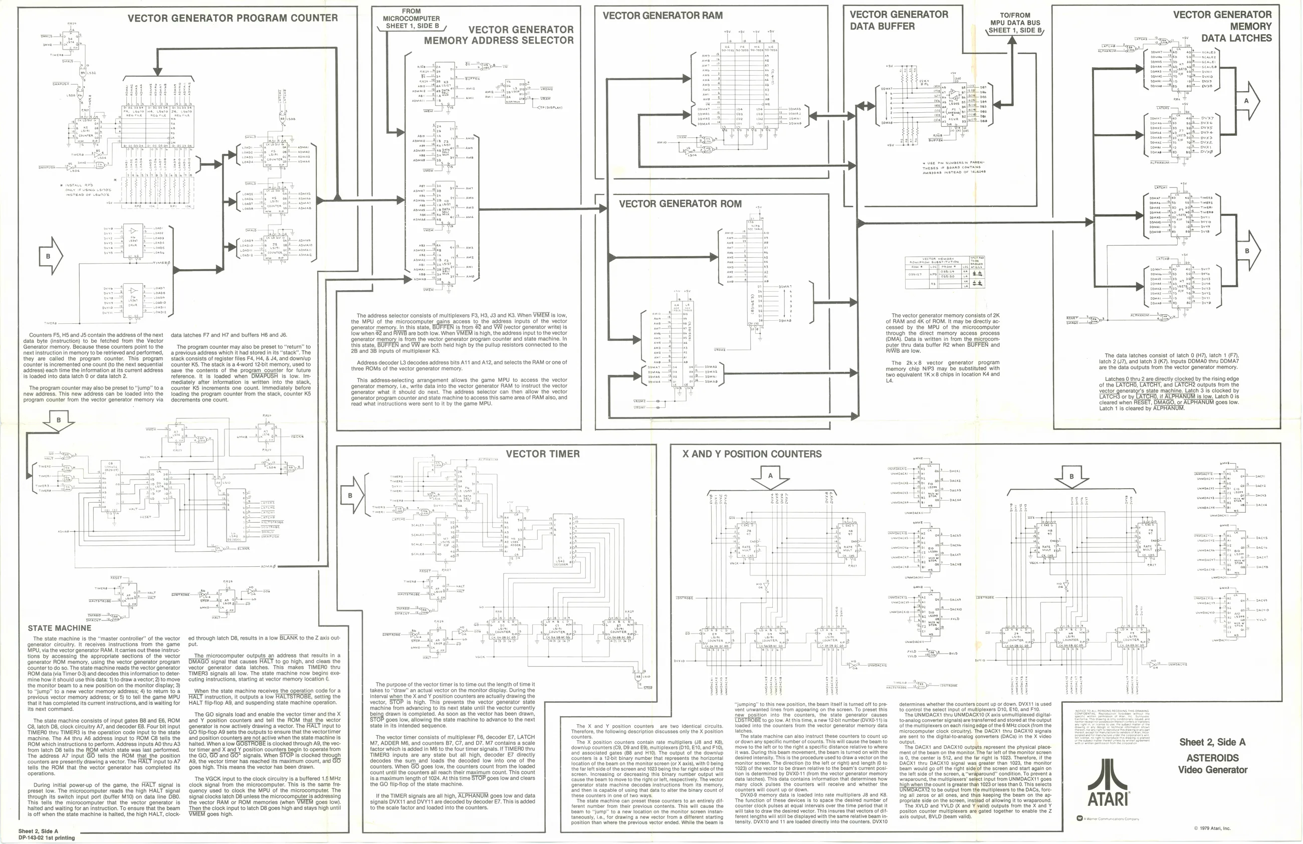
Counters F5, HS and JS contain the address of the next data byte (instruction) to be fetched from the Vector Generator memory. Because these counters point to the ‘ext instruction in memory to be retrieved and performed, they are called the program counter. This. program Counter is incremented one count (to the next sequential ‘address) each time the information at its current address 's loaded into data latch 0 or data latch 2. “The program counter may also be preset to “jump” toa new address. This new address can be loaded into the ‘program counter from the vector generator memory via data latches F7 and H7 and butters H6 and J6.
‘The program counter may also be preset to “return” to ‘previous address which it had stored in its stack”. The stack consists of register fles F4, H4, & J4, and downlup ‘counter KS, The stack is a 4word 126it memory, used to save the contents of the program counter for future reference. It is loaded when is Tow. Im mediately after information is written into the stack, Counter KS increments one count. Immediately before loading the program counter from the stack, counter KS decrements one count.
‘STATE MACHINE
‘The state machine Is the " ‘generator circuitry. MPU, via the vector aster controller" of the vector receives instructions from the game snerator RAM. It carries out these instruc: tone by accessing the appropiat.soctons af the vector generator BOM momory, ing the vetergoneatr program Scuntr todo to Tne stato machine reads Ns vector gnertor OM data ia Timer) and decodes thsinformation oder ‘ine how shoul use ths Gate) to raw a ecto 2} fo move the monitor beam to {4 through latch D8, results in a low BLANK to the Z axis outut
The microcomputer outputs_an address that results in a DMAGO signal that causes HALT to go high, and clears the vector generator data latches. This makes TIMERO thru ‘TIMERS signals all low. The state machine now begins exe- ‘outing Instructions, starting at vector memory location ( ‘The address selector consists of multiplexers F3, H9, J3 and KS. When VMEM is low, the MPU of the microcomputer_gains access to the address inputs of the vector generator memory. In this state, Is from &2 and VW (vector generator write) is, ow when 82 and FIWE are both low. When VMEM is high, the address input tothe vector, generator memory is from the vector generator program counter and state machine. In {his otato. BUFFEN and VW are both held nigh bythe pullup resistors connected to the 2B and 3B inputs of multiplexer K3.
Address decoder L3 decodes address bits A11 and A12, and selects the RAM or one of three ROMs of the vector generator memory.
This address-selecting arrangement allows the game MPU to access the vector ‘generator memory, Le., write data into the vector generator RAM to instruct the vector Generator what It'should do next. The address selector can then allow the vector ‘Generator program counter and state machine to access this same area of RAM also, and ead what instructions were sent to It by the game MPU.
VECTOR TIMER The vector ge of RAM and 4K of ROM. It may be directly accessed by the MPU of the microcomputer rator memory consists of 2K
through the direct memory access process (OMA, Data is written in from the microcompbuter thru data buffer R2 when BUFFEN and RIW are low.
The 2kx8 vector generator program memory chip NIP3 may be substituted with two equivalent 1K x8 chips in location K¢ and Us
X AND Y POSITION COUNTERS
its next command, ‘The state machine consists of input gates B8 and E6, ROM 8, latch D8, clock circuitry A7, and decoder E8. Four bit input TTIMERO thru TIMERG Is the operation code input to the state machine. The A4 thru AB address input to ROM C8 tells the ROM which instructions to perform. Address inputs AO thru A3 from latch 8 tells the ROM which state was last performed. ‘The address A7 input GO tells the ROM that the position ‘counters are presently drawing a vector. The HALT input to A7 tells the ROM that the vector generator has completed its ‘operations.
During initial power-up of the game, the HALT signal is preset low. The microcomputer reads the high HALT signal 'M10) on data line OBO. This tells. the microcomputer that the vector generator is halted and waiting for an instruction. To ensure that the beam Is off when the state machine is halted, the high HALT, clockthrough its switch input port (butt
Sheet 2, Side A 1DP-143.02 1st printing ‘position on the monitor display; 3) to “Jump” to a new vector memory address: 4) to return to a previous vector memory address; or 5) to tell the game MPU ‘that it has completed its current instructions, and is wating for When the state machine receives the operation code for a HALT instruction, it outputs a iow setting the HALT flip-flop A9, and suspending state machine operation ‘The GO signals toad and enable the vector timer and the X ‘and Y position counters and tell the ROM that the vector ‘Generator is now actively drawing a vector. The HALT input to GO fliptiop AG sets the outputs to ensure that the vectortimer {and position counters are not active when the state machine Is hhaltod. When a low GOSTROBE is clocked through AS, the vector timer and X and ¥ position counters begin to operate trom the GO, GO and GO* sionals, When STOP is clocked though ‘AG, the vector timer has reached its maximum count, ard {908s high. This means the vector has been drawn. ‘The VGCK input to the clock circuity is a buffered 1.5 MHz ‘clock signal from the microcomputer. This is the same fre- ‘quency used to clock the MPU of the microcomputer. The ‘signal Clocks latch D8 unless the microcomputers addressing the vector RAM or ROM memories (when ‘goes fow). ‘Then the clock input to latch D8 goes high and stays high until ‘9088 high. ‘The purpose of the vector timer s to time out the length of time it takes to “sraw” an actual vector on the monitor display. During the Interval when the X and Y position counters are actually drawing t vector, STOP is high. This prevents the vector generator state ‘machine from advancing to its next state until the vector currently being drawn is complete, As soon a the vector has boon drawn, ‘g0es low, allowing the state machine to advance to the next state In its intended sequence. The X and Y position counters are two Identical circuts. ‘Therotor, the following description discusses only the X position counters ‘The X postion counters contain rate multiplirs (J8 and KE), <downlup counters (69, D3 and E8), multiplexers (010, €10, and F10), ‘and associated gates (B8 and Hi), Tho output of the downlup ‘counters 1s a 121 binary number that represents the horizontal “The vector timer consists of multiplexer F6, decoder £7, LATCH M7, ADDER MB, and counters B7, C7, and O7. M7 contains a scale factor which is added in M6 to the four timer signals. if TIMERO thru TIMERS inputs are any state but all hgh, decoder €7 directly decodes the sum and loads the decoded’ low into one of tt location ofthe beam on the monitor screen (or X axis), with O being counters, When GO goes low, the counters count from the loaded tho ar ado ofthe saan and 23 beng to aright side of ne ‘count until the counters all reach thelr maximum count. This count RN ee a eee a Ele Marner ceo aa is a maximum length of 1024. At this time STOP goes low and clears ‘cause the beam to move to the right or left, respectively. The vector the GO flipflop of the state machine. ‘Generator state machine decodes Instructions trom lis memory, {and then is capable of using that data to alter the binary count of It the TIMER signals are all high, ALPHANUM goes low and data signals DVX11 and DVY11 are decoded by decoder E7. This is added tothe scale factor and loaded into the counters. ‘3 This wil cause the ‘beam to “jump” to a new location on the monitor screen instar taneously, ie, for drawing a new vector {rom a different stating position than where the previous vector ended. While the beam Is “jumping” to this new position, the beam i vent unwanted lines trom appearing on the screen. To preset th Into the ‘counters, the state ‘generator ‘causes Yo golow. At this timo, ariew 12-bit number (DVXO-1) 5 loaded into the counters from the vector generator memory data latches. "The state machine can also instruct these counters to count up ‘or down any specific numberof counts. This will cause the beam to ‘move to the lft orto the right a specific distance relative to where During this beam movement, he beam Is turned on withthe nsiy. This Is the procedure used to draw a vector onthe ‘monitor screen. The direction (to the
at ‘many clock pulses the counters will receive Counters wil Count up or down, BVXO9 memory ‘Tho function of th counter clock pulses at equal int Will take to draw the desired vector. This Insure t {erent lengths wil stl be cisplayed withthe same relative beam in- ‘BVK10 and 11 are loaded directly into the counters, DVX10 ‘The data latches consist of latch 0 (H7), latch 1 (F7), latch 2 (7), and latch 3 (K7). Inputs DDMAO thry DDMA7 ‘are the data outputs from the vector generator memory. Latches 0thru2 are directly locked by the rising edge of the LATCHO, LATCHT, and LATCH? outputs from the vector generatgr’s state machina. Latch 3 Is clocked by oF by_ it ALPRANUM is low. Latch 0 is Cleared when RESET, DMAGO, oes low, , OMAGO, or Latch 1 is cleared by ALPHANUM.
ee
{etormines whether the counters count up or down. DVX11 is used to control the select input of multiplexers D10, £10, and F10. ‘Te UNMOAGX' thru UNMDAGX10 0X axis unmultiplexed digital toanalog converter signals) are transferred and stored atthe output ‘ofthe multiplexers on each rising edge ofthe 6 MHz clock trom the ‘microcomputer clock cirulty). The DACK? thru DAGX10 signals are sent to the digitaltoanalog converters (DACs) in the X video output i ‘The DACX! and DACX10 outpets represent the physical place: ‘ment ofthe beam on the monitor. The fa elt of the monitor sereen {8.0, the center Is 512, and the far right Is 1023. Therefor, Ifthe ‘DAGXT thru DAGX10 signal was greater than 1023, the monitor ‘beam would go off the “ight sidgoot the screen and start again on {tho Tot side ofthe screen, ind" condition. To provent @ ‘wraparound, the multiplexers’ eect input from UNMOACXC1 goes hwhon the count is greater than 1023 or lees than O. Ths selects LUNMBACETD tobe output trom the multiplners tothe DACs, fore ing all zeros or all ones, and thus keeping the beam Dropriate side on the sereen, instead of allowing it to wraparound. ‘The XVLD and YVLD (X and ¥ vaig) outputs from the X and ¥ positon counter multiplexers are gated together to enable the Z axis output, BVLO (beam vali). ‘the ap-
(© 1979 Ata, ne.