Smokey Joe TM-116 1st Printing
Smokey Joe (Atari, Inc., 1978) · Technical Manual · 132 pages · 51 sections · original scan
Operation, Maintenance and Service Manual
Complete with Illustrated Parts Catalog
GAME SERIAL NUMBER LOCATION
Your game’s serial number is stamped on the circuit (back) side, bottom right corner, of the printed circuit board—see the illustration below. The same number is also stamped on the label located on the rear of the game cabinet. Please mention this number whenever calling your distributor for service. tee
Smokey Joe”
Operation, Maintenance and Service Manual
Complete with Illustrated Parts Catalog TARI INC. 1265 BORREGAS AVENUE P.O. BOX 9027 SUNNYVALE, CALIFORNIA 94086 408/745-2000 + TELEX 35-7488
A ATARI
A Warner Communications Company QD
Copyright © 1978 by Atari, Inc. All rights reserved Motorola and TEC service manuals reprinted by permission of Motorola Data Products and TEC Videoelectronics, Inc. No part of this publication may be reproduced by any mechanical, photographic, or electronic process, orin the form of a phonographic recording, nor may it be stored in a retrieval system, transmitted, or otherwise copied for public or private use, without permission from the publisher.
For permissions request, write:
ATARI INC 1265 Borregas Avenue P.O.Box 9027 Sunnyvale, California 94086
7G Lithographed in the U.S.A
ii Smokey Joe
TABLE OF CONTENTS
LOCATION SETUP INTRODUCTION GAME INSPECTION....... LOCATION OF SERIAL NUMBER INSTALLATION REQUIREMENTS. . cece eee Power Requirements and Line Voltage Selection bees Temperature Range. ............... ewe ek tees 7 Humidity Range . Location Space Requirements. . Type of Power Cord ............ INTERLOCK AND POWER ON/OFF SWITCHES . VOLUME CONTROL ........... ue eee en SELF-TEST PROCEDURE cece see OPERATOR OPTIONS bones sees DAOB>
xzOmM
GAME PLAY A. ATTRACT MODE |... 00.00.0000 eee voce BT B. READY-TO-PLAY MODE. err C. PLAYMODE «2.0.0 veces 22
MAINTENANCE AND ADJUSTMENTS A. CLEANING ..... Sei seis 6 tis wage eae © eee gee vr come B. COINMECHANISM ...... 0.0.0.0... 000000 fig gies sous aes Components on Coin Door....... ee ere ea Access to Coin Mechanism. . Cleaning of Coin Paths Lubrication . Adjustment of Coin Switch Trip Wire . : Mechanical Adjustments on Coin Mechanism : General Troubleshooting Hints . . C. FUSE REPLACEMENT D. TVMONITOR ADJUSTMENTS. £, TVMONITOR REMOVAL......... F. LAMPREPLACEMENT ........ nna G. SWITCH (LED) AND BUTTON REPLACEMENT. . eee eee BB H. STEERING PCB REPLACEMENT............... sues as ee BD
THEORY OF OPERATION A. GENERAL INFORMATION eee ee cece eee AT B. POWER SUPPLY ..... 00.00 2. 42 C. CRYSTAL-CONTROLLED OSCILLATOR AND TV SYNC GENERATOR....... 42 D. MICROCOMPUTER ee cb4 oes RE GA nt ee ge uaa ea 2 AS E, MICROPROCESSOR........... eee wie wins cme eee gene oi 45 F. MICROPROCESSOR CLOCK tte eee ee pues ce owes epee vere ory we AS G. MICROPROCESSOR WATCHDOG ............- fat eee eee « BB H. ALPHANUMERIC GENERATOR tgs F auet ems biases pews Be 45
- PLAYFIELD GENERATOR...... fee cence 46
Smokey Joe
TABLE OF CONTENTS
iv CAB VIDEO GENERATOR ... TAIL VIDEO GENERATOR STEERING CONTROL LOGIC ... . HORN AND BELL GENERATOR ....... MOTOR AND SIREN GENERATOR .... BANG AND SCREECH GENERATOR . .. AUDIO OUTPUT .................-5 ox SINGLE AUDIO AMPLIFIER... 00.0.0 eee 5 ILLUSTRATED PARTS CATALOG......................... 5-1
TV MONITOR SERVICING INFORMATION QRPOZErAD
MOTOROLA Service Manual A. GENERAL INFORMATION ............- boven eeee B. SERVICE NOTES . Circuit Tracing. ...... Component Removal .... CRT Replacement . . . Adjustments . bee wee an . . Regulator Adjustment ................. Lee e eee eee beeen eee Horizontal Hold/Oscillator Adjustment Vertical Height/Linearity Adjustment . Focus Adjustment ....... Monitor Servicing C. THEORY OF OPERATION ... Power Supply . +73 Volt Supply... oe Video Amplifiers and Output . beeen D. HORIZONTAL DEFLECTION CIRCUITS . Phase Detector ....... Horizontal Oscillator .. . veces Horizontal Pulse Shaper and Driver : oe bene . oe Horizontal Outpttt cs. ces cas cae pies pes ewe cw pet pen ces cwieetende Sync Circuits .... 20.00.00. e eee Vertical Oscillator and Output . . a beeen bene eee Spot Kill......... SI 39 7 Blanking Amplifier... 0.0.00. 0 0c eee cece eevee 610 QRSTSLLLLELL
A. GENERAL ..... 200.0202 0 cece ce eee cee ences 618 B. SPECIFICATIONS ............. eee eee 618
Smokey Joe
Power Supply Input. Power Consumption Picture Tube High Voltage . Horizontal Retrace Time Resolution
Figure 1-1 Figure 1-2 Figure 1-3 Figure 1-4 Figure 1-5 Figure 2-1 Figure 2-2 Figure 2-3 Figure 3-1 Figure 3-2 Figure 3-3 Figure 34 Figure 3-5 Figure 3-6 Figure 3-7 Figure 38 Figure 3-9 Figure 3-10 Figure 3-11 Figure 3-12 Figure 4-1 Figure 4-2 Figure 4-3a Figure 4-3b Figure 44 Figure 4-5 Figure 46 Figure 4.7 Figure 48 Figure 49 Scanning Frequency . Tone Burst Amplifier . Environment TABLE OF CONTENTS
-. 618
ee - 618 ht BEE 6-18
LIST OF ILLUSTRATIONS
Location of Voltage-Changing Plugs on the Power Supply bees Location Space Requirements Location of Interlock and Power On/Off Switches . Location of Volume Control and Self-Test Switch. . Option DIP Switches on Game PCB .... Attract Mode... ... Ready-to-Play-Mode Play Mode. : Coin Door Assembly . . Hinging Open the Magnet Gate Assembly Removal of Coin Mechanism . Surfaces to Clean Inside the Coin Mechanism Removal of Plate Covering Rear of Coin Slot . Close-Up View of Lubrication Point .... Detail View of Coin Switch and Trip Wire. . Coin Mechanism, Exploded View . . Locations of Adjustments on TV Chassis. . TV Monitor Removal... . . Fluorescent Lamp Replacement . : Switch and Button Replacement. . err Functional Block Diagram of Smokey Joe Game . Block Diagram of the Smokey Joe PCB. 1Mhz Timing Chart (Normal Operation) . . 750Khz Timing Chart (Self-test Only). . Steering Printed Circuit Assembly Output Pulses . Smokey Joe Harness Schematic Diagram (2 Sheets) . . Smokey Joe PCB Schematic (6 Sheets) Coin Door Schematic ..... . ; Type B Power Supply Schematic Diagram Single Audio Amplifier Schematic Diagram . . . 1-3
vee TS beeen we 18
Smokey Joe v
LIST OF ILLUSTRATIONS
Figure 5-1 Figure 5-2 Figure 5-3 Figure 5-4 Figure 5-5 Figure 5-6 Figure 5-7 Figure 5-8 Figure 5-9 Figure 5-10 Figure 5-11 Figure 5-12 Figure 5-13 Figure 5-14 Figure 5-15 Figure 5-16
Figure 6-1 Figure 6-2 Figure 6-3 Figure 6-4 Figure 6-5 Figure 66 Figure 6-7 Figure 6-8 Figure 6-9 Figure 6-10 Figure 6-11 Figure 6-12 Figure 6-13 Figure 6-14 Figure 6-15 Figure 6-16 Figure 6-17 Figure 6-18 Figure 6-19 Figure 6-20 Figure 6-21
vi Smokey Joe ILLUSTRATED PARTS CATALOG
Final Cabinet Assembly... . TV Monitor Assembly . Control Panel Assembly . . Coin Door Assembly . Front Bezel Assembly ... . Coin Lockout Assembly ... . Coin Switch Assembly... . . net fie . an Type B Power Supply Assembly ene ene cect e tenet eens 514 Fluorescent Lamp Assembly . . bee eee eee eee 5-16 RF Shield Board Assembly . . 5-18 Steering Wheel Assembly . 520 Foot Pedal Assembly. . fet bee beens vee 522 Start Button Assembly. ...............0055 beeen eee ee .. 524 Single Audio Amplifier Assembly 5-26 On/Off Switch Assembly. . 5-28 Smokey Joe PCB Assembly 5-31
TV MONITOR SERVICING INFORMATION
Motorola Monitor Circuit Board in Service Position................... 62 Motorola Monitor Block Diagram............ 63 +73 Volt Supply Circuit . . . 63 Motorola Monitor Vertical Drive Waveform. . 63 Motorola Monitor Video Amplifiers and Output Circuit becca 64 Motorola Monitor Horizontal Deflection Circuit ................... 65 Motorola Monitor Horizontal Deflection Waveforms .............. 66 Motorola Monitor Horizontal Output Circuit . . . . .. 66 Motorola Monitor Sync Circuit.............. eben eee eee .. 67 Motorola Monitor Vertical Oscillator Circuit . . . - 67 Motorola Monitor Spot Killer Circuit ...... bie ha ewe we 1 68 Motorola Monitor Blanking Amplifier Circuit......... veces 66 Motorola Monitor Chassis Rear View— Component Location : 69 Motorola Monitor Circuit Board Detail—Solder View ................ 610 Motorola Monitor Schematic Diagram .......-.-..-.-+ Motorola Monitor Circuit Board Detail— Component Location. TEC Monitor Chassis, Rear View . . . . eens TEC Monitor Chassis, Top View. . . . TEC Monitor Printed Circuit Board, Top View TEC Monitor Schematic Diagram ...............- TEC Monitor Wiring Diagram . . -. 623
LIST OF TABLES
Table 1-1 Self-Test Procedure ... Table 1-2 Operator Options Table 1-3 Points Required to Earn Extended Play . Table 4-1 Microprocessor Signal Descriptions. .
| Table 6-1 | Motorola Monitor Electrical Specifications . . . | Sean | Lee |
| Table 6-2. | Motorola Monitor Replacement Part Numbers ..................- | .. 615 | |
| Table 6-3 | TEC Monitor Replacement Part Numbers ..........0.00000 | 00000 | e ee 6-20 |
Smokey Joe vii
This page carries no recoverable text. It is a drawing or a photograph. See the original scan.
LOCATION SETUP
A, INTRODUCTION
SMOKEY JOE is a one-player driving game which is packaged in a distinctively styled upright cabinet that rests directly on the floor. A 23-inch TV monitor is mounted in the top front of the cabinet, with the monitor viewing screen slightly tilted from the vertical Player-operated controls are mounted directly below the TV monitor viewing screen on the front of the game cabinet. The controls consist of a steering wheel, an accelerator foot pedal, a pushbutton for track difficulty, a front start pushbutton, and a back start pushbutton.
Two identical coin mechanisms are mounted on the lower front center of the game cabinet, below the steering controls. Either of these two mechanisms can initiate play. The cash box is located behind a locked access door below the coin mechanisms.
Smokey Joe -
The player's objective is to manipulate the Smokey Joe firetruck along the track in a race against time. The player must avoid sliding in oil pools in the road, or dropping into sand pits, as well as avoiding other cars, while keeping the Smokey Joe firetruck within the boundaries of the road. The player has the option of driving either the cab or the tail
Acceleration is as in a real firetruck with cab to tail “cooperative” interaction. Accelerate slowly. If the firetruck goes into an oil slick or sand pit, it slides, with sound of sliding from the game cabinet speaker. If the firetruck drives into a track boundary, a tree, or another car, a crash sound will be heard from the game cabinet speaker and the TV monitor viewing screen will flash.
B. GAME INSPECTION Follow the procedures below to ensure that your game is in perfect condition.
- Examine all external parts of the game cabinet for dents, chips, or broken parts.
- After determining that the game has been received in good condition, unlock and open the rear access door. Carefully inspect the interior and verify that:
@ All plug-in connectors are firmly seated.
@ All integrated circuits in sockets on the game printed circuit board are firmly seated.
@ = The fuses are all seated in their holders.
@ No harness wires are disconnected.
@ No loose foreign objects are present, especially metal objects that could cause electrical problems.
Be sure all major assemblies are checked. Check the game printed circuit board (PCB), the transformer, the two coin mechanisms, the speaker, the fluorescent light, and the player controls. Also, be sure the TV monitor is secure in its mounting.
C. LOCATION OF SERIAL NUMBER The serial number for Smokey Joe is located on a metallic label in the upper left-hand corner on the back of the game cabinet. This serial number also appears in the corner (common to both edge connectors) on the back of the PCB, inside the game cabinet. See the illustration on the inside front cover of this manual.
1-2 Smokey Joe D. INSTALLATION REQUIREMENTS
Smokey Joe is shipped for operation at 110 VAC, 60 Hz. Power consumption is approximately 150 watts. However, if your local voltage is not 110 volts, follow this procedure. You must select one of four connectors at the power supply and plug it into the voltage selection socket. Figure 1-1 shows the four connectors with one of them plugged in. The plugs are identified by wire color as listed in this figure. Note that there are two basic operating voltages — 110 VAC, 60 Hz, and 220 VAC, 50 Hz, with provisions for low line voltage in each case. To insure proper operation, measure line voltage. If voltage is consistently below 100 V (for 110 VAC lines) or consistently below 210 V (for 220 VAC lines), use the low-voltage connections. Use the black plug for low 110 VAC lines and the green plug for low 220 lines.
Temperature Range
Location and storage should not be below 0 degrees Celsius (32 degrees Fahrenheit), and no higher than 49 degrees Celsius (120 degrees Fahrenheit).
Humidity Range
Relative humidity for location or storage should be no more than 95%
Location Space Requirements
The game requires a minimum of: @ 168 centimeters (66 inches) of vertical clearance
@ 65 centimeters (25.5 inches) of width space
@ 175 centimeters (69 inches) of depth space See Figure 1-2 for details.
Type of Power Cord
Atari has added a strain relief power cord to Smokey Joe. The advantage of this type of power cord is that, if pulled accidentally, the strain relief will hold the cord in place at the pedestal base. The plastic strain relief “cushions” the impact of the shock and prevents the cord from pulling the wires out of the harness connector. Check the power cord assembly periodically for damage.
LINE VOLTAGE-CHANGING VOLTAGE PLUG WIRE COLOR NOTE: [__95 VAC BLACK Power supply i ; jpply in your game may not 110 VAC ORANGE include fuses F3, F4, and F5. installed at factor: 210 VAC 220 VAC
8 Amp, 125V.
2.5 Amp. 125 V. Slow—blow ON/OFF AND C4 INTERLOCK SWITCH
3.amp, 250V. Slow - blow
Figure 1-1 Location of Voltage-Changing Plugs on the Power Supply
E. INTERLOCK AND POWER
| ON/OFF SWITCHES | 2. | Plug the AC power cord into a 110-volt source. (If |
To minimize the hazard of electrical shock while voltage is consistently less than 110 VAC, make sure you are working inside the game cabinet, two interlock that you use the black plug instead.) switches have been installed at the rear door assembly
| and at the coin door. These switches remove all power | 3. | Set the power on/off switch to the on position. |
from the game while the doors are open. To help you
| conserve energy, a power.on/off switch has been install- | 4. | Close both doors. Within approximately 30 seconds |
ed on the game so that it can be turned off during closed the TV monitor should display a picture. periods. This switch is located at the rear of the upright
| cabinet toward the top, as shown in Figure 1-3. | 5. | Slowly open each door until the TV monitor picture |
disappears. The picture should disappear when the Check for proper operation of the interlock swit- rear door is opened less than one inch from the top. ches by performing the following steps:
- If the results of Step 5 are satisfactory, the interlock
| 1. | Unlock and open the rear door assembly and the | switches are operating properly. If the picture does |
coin door. not disappear as described, check to see if the ap-
Smokey Joe 1-3
Figure 1-2 Location Space Requirements
1-4 Smokey Joe
SELF-TEST SWITCH
ON/OFF POWER SWITCH
INTERLOCK SWITCH
Figure 1-3 Location of Interlock and Power On/Off Switches
Smokey Joe 1-5
SELF-TEST SWITCH
VOLUME CONTROL
Figure 1-4 Location of Volume Control and Self-Test Switch
propriate switch is broken from its mounting or stuck in the on position.
- Close and lock both doors.
F. VOLUME CONTROL If volume is incorrect for your location, open the coin door and adjust the volume control. See Figure 1-4 for location of the volume control.
G. SELF-TEST PROCEDURE Smokey Joe will test itself and provide data to demonstrate that the game’s circuitry and controls are working properly. This procedure uses the TV monitor and the speakers; no additional equipment is required. SEE FIGURE 1-4 FOR LOCATION OF THE SELF-TEST SWITCH. To start the procedure over from the begin-
1-46 Smokey Joe ning, turn the switch off, then on again. This will return the test to Step 1 and can be done at any time during the procedure. See Table 1-1 for further details and instructions on the self-test. We suggest that you run the selftest procedure each time the coin box is emptied.
H. OPERATOR OPTIONS Options of the Smokey Joe game offer maximum player appeal for each game location. These options are listed in Table 1-2. They are preset for a certain game setup during production. To determine how the switches have been set for your game, compare the TV monitor viewing screen during the attract mode with the information in Table 1-2.
To change the toggle positions of the switch assembly and set the desired options, the printed circuit board (PCB) must be removed according to the following procedure.
- Unplug the game. Unlock and open the rear door assembly,
- Locate the radio frequency (RF) shield assembly immediately inside the cabinet on the right. See Figure 1-5. On one end of the box is a printed circuit board (PCB) with an edge connector coming from the edge of the board, (The RF shield assembly is an aluminum box with small holes.) Turn the three quarter-turn fasteners on the RF Shield assembly by turning the wing nuts % turn.
Carefully pull out the PCB and the RF shield board as one unit. These would not normally need to be separated when making option switch changes.
Set the switches for the desired options, as shown in Table 1-2.
Reinstall the PCB following steps 1 through 4 in reverse order. Do not force or bend the printed circuit board. Before reinstalling, always inspect the PCB for damage. Close and lock the rear access door.
Plug in the game and verify options functions by playing it.
8-TOGGLE DIP SWITCH 4-TOGGLE DIP switc bee’
Figure 1-5 Option DIP Switches on Game PCB
Smokey Joe 1-7
Table 1-1 Self-Test
TEST INSTRUCTION RESULTS IF TEST PASSES RESULTS IF TEST FAILS
| Unlock and open the coin | There are four ROM s pro- | 1, 2, 3 and/or 4 is displayed |
| door. Locate the self-test | grammed into Fire Truck. If | in the lower left corner of the |
| switch and turn to the | they all check satisfactorily, | TV screen. These numbers cor- |
| “on” position. | there is no visible change or | respond to the failing ROM or |
indication on the TY screen ROMs.
The ROM and RAM test Throughout the self-test, a set of will follow stationary graphics appear in a rainbow pattern (dark to light) from the left side to the right side of the screen.
ROM 1—ERROR ROM 4—ERROR
These examples represent two of the possible four ROM s which could be in error. If the zero-page RAM is bad, a0 is displayed in the lower left corner of the screen. A 5 is displayed if the screen RAM is bad
If the RAM s (zero-page and screen) check satisfactorily, there is no visible change on the TV screen.
Bad screen RAM_ Bad Zero-page RAM
The next phase of the selftest checks the LED switches and both steering wheels on each control panel Individually press the six LED switches. Turn each steering wneel The same pop sound occurs to the right, then back to. each time there is a change the left. Then reverse the in (the) direction in which the procedure wheel is being turned The LED's are on. An electronic “pop” sound occurs each time a switch is pressed, and again when the No sound indicates a stuck or switch is released broken switch, or an open or shorted harness
Trip the right and left “The pop sound occurs whenever coin switch wires. a coin switch wire is tripped
1-8 Smokey Joe
Table 1-2 Operator Options
OPTION
EXTENDED PLAY*
No Extended Play Liberal (Easy to Earn) Medium Conservative (Hard to Earn) 8-TOGGLE DIP SWITCH ON GAME PCB —TOGGLE NO:
ON ON ON OFF OFF ON OFF OFF
GAME TIME
60 Seconds 90 Seconds 120 Seconds 150 Seconds 4a0Z
omuc ON ON OFF OFF ON OFF ON OFF
GAME LANGUAGE
English ON ON Spanish OFF ON
French ON OFF
German OFF OFF
OPTION 4-TOGGLE DIP SWITCH ON GAME PCB —TOGGLE NO.: 3 4
N GAME COST O
T Free Play ON ON Two Plays Per Coin u OFF = ON One Coin Per Play 5 ON OFF
Two Coins Per Play 5 OFF OFF
*See Table 1-3 for point scores required to earn extended play.
Table 1-3 Points Required to Earn Extended Play
Game Length Setting
| 60 | 90 | 120 | 150 |
| seconds | seconds | seconds | seconds |
Extended Play Option Setting: Extended play granted for scoring.
| Liberal | 90 pts. | 140 pts. | 190 pts. | 240 pts. |
| Medium | 100 | 160 | 220 | 270 |
| Conservative | 120 | 180 | 240 | 300 |
Smokey Joe 1-9
This page carries no recoverable text. It is a drawing or a photograph. See the original scan.
GAME PLAY
Smokey Joe has three modes of operation:
@ Attract — power applied or at the end of a game @ Ready-to-Play — coins accepted @ Play — after one of the Start buttons is activated
A. ATTRACT MODE (See Figure 2-1) The attract mode begins when power is applied to the game and the power switch is turned on. (The power on/off switch is located at the back of the cabinet, as shown in Figure 1-2.) This mode also occurs at the end of every game. When the proper amount of coins clear the coin acceptor, the attract mode ends.
During the attract mode a firetruck is shown in the middle of the screen with the roadway scenery and hazards passing by. BONUS information and TOP SCORE information appear (alternately) at the top of the viewing screen. The previous game SCORE and driver rating message (SORRY, SO-SO, GOOD or ACE), appear alternately at the bottom of the screen. The player controls and game sounds are inactive during this mode.
Smokey Joe By
SCORE
Figure 2-1 Attract Mode /Ready-to-Play Mode
B. READY-TO-PLAY MODE (See Figure 2-1) When the correct amount of coins clear the coin acceptor, the ready-to-play mode is initiated. There is no change on the TV monitor from the attract mode. The Start buttons on the control panels flash on and off according to the amount of credit registered for the game. If there is sufficient credit for another game the front and back start button will flash. It is during the ready-to-play mode that players have the opportunity to select the “Hard” or “Easy” track. If the track select button is lit, the hard track will be displayed for the duration of one game. The button has to be reactivated (lit) at the beginning of each game for the hard track to be displayed
This mode also occurs at the end of game play if there are credits remaining.
Cc. PLAY MODE (See Figure 2-2) The play mode begins when one of the start buttons is pressed. The player steers either the cab or the tail
See Section H in Chapter 1 for various operator options (game time, cost, extended piay levels, etc.) It is possible to influence the direction of one part of the firetruck by radically steering the other. For ex-
2-2 Smokey Joe Figure 2-2 Play Mode
ample, if the cab is steered extremely to one side or the other, the tail steering will be hampered and a “static” noise will be heard over the game speakers.
The object of the game is to crash as little as possible, thereby obtaining a high point score. The front player operates the accelerator foot pedal.
Whenever any part of the firetruck comes in contact with the side of the road (sidewalk) or another obstacle, the TV monitor flashes, all motion freezes, a crash sound is heard over the speakers, and the word CRUNCH is displayed on the screen.
Points are awarded in increments of ten. Each time ten points are earned (by passing certain invisible points on the track), the sound of three ringing bells is heard over the game speakers. When extended play is earned, the track goes into a white video display for the re. mainder of such bonus time and the EXTENDED PLAY tone is heard. Other game sounds include the:
Engine sound Siren sound Screech sound Horn sound Crash sound
Due to its solid-state electronic circuitry, this Atari unit should require very little maintenance and only occasional adjustment. Information given in this chapter and elsewhere in this manual is intended to cover most servicing situations that may be encountered at a game site. The procedures given are in sufficient detail to be understood by a person with moderate technical background.
If reading through this manual does not lead to solving a specific maintenance problem, you can get help from the following two Atari Customer Service offices
AtariJNew Jersey Customer Service Office 46 Colonial Drive, Piscataway, NJ 08854 Telex 37-9347 (Monday-Friday, 8:30-5 pm Eastern time)
Dial toll-free from anywhere in the shaded area on map, below (800) 631-5374
From New Jersey and elsewhere in the US dial (201) 981-0490.
Atar/California Customer Service Office 1344 Bordeaux Drive, Sunnyvale, CA 94086 Telex 17-1103 (Monday-Friday, 7:30-4 pm Pacific time)
From California, Alaska and Hawaii dial (408} 745-2900, From the remaining 47 states, dial toll-free (800) 538-1611 MAINTENANCE AND
ADJUSTMENTS
Smokey Joe
A. CLEANING The exteriors of game cabinets and Plexiglas® panels may be cleaned with any non-abrasive household cleaner. If desired, special coin machine cleaners that leave no residue can be obtained from your distributor. Do not dry-wipe the acrylic plastic panels, because any dust can scratch the surface and result in fogging the plastic
B. COIN MECHANISM Components On Coin Door Figure 3-1 shows the back side of the coin door assembly where the game’s two coin mechanisms are mounted. Included is the lock-out coil assembly; the lock-out wires are connected to this assembly but are hidden behind the coin mechanisms. Powering the game causes the lock-out wires to retract far enough to allow genuine coins to reach the coin box. When AC power to the game has already been turned off, the lockout coil is de-energized, causing the lock-out wires to move out far enough to divert coins’to the return chute.
Directly below each coin mechanism is a secondary coin chute and a coin switch with a trip wire exten-
LOCK-OUT COIL LAMP HOLDER ding out to the front edge of the chute. When the trip wire is positioned correctly, a coin passing down the secondary chute and into the coin box will momentarily push the trip wire down and cause the switch contacts to close.
Also shown in the photograph is a slam switch assembly. It has been included to defeat any players who might try to obtain free game plays by violently pounding on the coin door to momentarily close the contacts on a coin switch. The slam switch contacts connect to the microcomputer system, which will ignore coin switch signals whenever the slam switch contacts are closed.
Access to Coin Mechanisms To remove jammed coins, and for maintenance cleaning, each magnet gate assembly can be hinged open without removing it from the door, as shown in Figure 3-2. Or, if necessary, each coin mechanism can be entirely removed from the door merely by pushing down on a release lever and simultaneously tilting the mechanism back, then lifting it up and out. This is shown in Figure 3-3.
Plexiglas® is a registered trademark of Rohm & Haas Company.
Figure 3-1 Coin Door Assembly
3-2. Smokey Joe Figure 3-2 Hinging Open the Magnet Gate Assembly
Figure 3-3 Removal of Coin Mechanism
Cleaning of Coin Paths
By talking to many operators, we have found that the best method of cleaning a coin mechanism is by using hot or boiling water and a mild detergent. A toothbrush may be used for those stubborn buildups of residue. After cleaning, flush thoroughly with hot or boiling water, then blow out all water with compressed air.
Figure 3-4 shows the surfaces to clean inside the coin mechanism. These include the inside surface of the
‘ ae (CLEAN BOTH SURFACES WHERE COIN ENTERS THE MECHANISM, AS WELL AS THE MAGNET)
Figure 3-4 Surfaces to Clean Inside the Coin Mechanism mainplate, and the corresponding surface of the gate assembly. There may also be metal particles clinging to the magnet itself. fo remove these you can guide the point of a screwdriver or similar tool along the edge of the magnet.
If coins are not traveling as far as the coin mechanisms, you will need to clean the channel beneath the coin slot. To gain access to this channel, use a 3/8-inch wrench and remove all three nuts that secure the cover plate (refer to Figure 3-5). Removing the plate will provide access to the entire channel.
Also clean the inside surfaces of the secondary coin chutes, but when doing this be careful not to damage or bend the trip wires on the coin switches.
Figure 3-5 Removal of Plate Covering Rear of Coin Slot
Lubrication Do not apply lubrication to the coin mechanisms. The only points that may need lubrication (and only rarely) are the shafts of the scavenger buttons (coin rejection buttons) where they pass through the coin door. Apply only one drop of light machine oil, and be positive that no oil drops down onto a coin mechanism. Figure 3-6 shows this lubrication point.
Adjustment of Ccin Switch Trip Wire In order for a coin switch to operate reliably when a coin travels down the secondary coin chute, the rest position of its trip wire should be as shown in Figure 3-7. Use extreme care when handling or touching these wires.
Smokey Joe 3-3
MANUALLY HOLD DOWN REJECTION BUTTON AND APPLY ONE DROP HERE
LOCK- OUT WIRE
Figure 3-6 Close-Up View of Lubrication Point
In Figure 3-7 you will note that the coin switch trip wire is oriented into the “V” of the secondary coin chute. The wire should extend to only about 1/8” beyond the chute.
A retaining clip holds the wire onto the switch actuating stud. If you should loose a retaining clip, all is not lost. Just crimp the switch actuating stud over the trip wire with a pair of pliers.
Mechanical Adjustments on Coin Mechanism Coin mechanisms are adjusted prior to shipment from the factory and normally will retain these adjustments for many months. If, due to wear or other causes, it becomes necessary to make new adjustments, remove the coin mechanism from the coin door. Then take it to a clean well-lighted area where it can be placed in a vertical position on a level surface (such as a bench top). Besides a screwdriver, you will need a set of several coins, including both new and old, worn ones. Figure 3-8 shows an exploded view of the mechanism and gives procedures for adjusting the kicker, separator, and the magnet gate. These adjustments should only be done by someone who has experienced in servicing coin mechanisms and who understands their operation.
3-4 Smokey Joe CORRECTLY ADJUSTED TRIP WIRE
Figure 3-7 Detail View of Coin Switch and Trip Wire
General Troubleshooting Hints The first action is to look for jammed coins. After these have been removed, examine the coin path for presence of foreign material or loose objects (such as chewing gum, small metallic objects, paper wads, etc). In cases where game usage is heavy, it may be necessary to clean the entire coin path periodically, in order to prevent build-up of contaminants that can hinder the movement of coins through the mechanisms. Also confirm that the trip wire on each coin switch is intact, and is properly adjusted. If troubles still persist, check the conditions and positions of the lock-out wires, and the mechanical adjustments on the coin mechanisms, before suspecting the electronics. If a coin mechanism
ITEM IDENTIFICATIONS Kicker and Separator Screws Washers Kicker Separator Gate Lever Spring Gate Pivot Pin inplate Assembly ‘C” washer Rail Gate Assembly Cradle Assembly
- Upper Gate Pivot Spring 14 Undersize Lever Assembly 15 Magnet Gate Assembly 16 Magnet Gate Adjuster 17 Retaining Screws 18 Coverplate Assembly 19 Return Coverplate 20 Coverplate 21 Mounting Studs 22 Lower Gate Pivot Spring 23 Coin Release Lever Kicker and separator 1, Set the acceptor with the back of the unit facing you in the test position.
- Loosen the kicker and separator screws (1) and move the kicker (3) and the separator (4) as far to the right as they will go. Lightly tighten the screws.
- Insert several test coins (both old and new) and note that some are returned by striking the separator.
- Loosen the separator screw and move the separator a slight amount to the left. Lightly retighten the screw.
- Insert the test coins again and, if some are still returned, repeat Step 4 until all the coins are accepted.
- Loosen the kicker screw and move the kicker as far to the left as it will go. Lightly retighten the screw.
- Insert the test coins and note that some are returned.
- Loosen the kicker screw and move the kicker a slight amount to the right. Lightly retighten the screw.
- Insert the test coins again and, if some are still returned, repeat Step 8 until all the coins are accepted.
- Be sure that both screws are tight after the adjustments have been made.
Magnet gate . Set the acceptor with the front of the unit facing you in the test position. . Turn the magnet gate adjusting screw (16) out or counterclockwise until none of the coins will fit through.
- With a coin resting in the acceptor entrance, turn the adjuster in or clockwise until the coin barely passes through the magnet gate.
- Test this adjustment using several other coins (both old and new) and, if any fail to pass through the magnet gate, repeat Step 3 until all the coins are accepted.
- Fix the magnet gate adjusting screw in this position with a drop of glue. va
Additional Cleaning
- Remove the transfer cradle (12) and the undersize lever (14).
- Use a pipe cleaner or similar effective cleaning tool to clean the bushings and pivot pins.
- Replace the transfer cradle and the undersize lever.
- To be certain the coin mechanism is completely free of any residue, place the mechanism in boiling water for several minutes. Caretully remove it and let it air-dry completely before reinstalling in the door.
Figure 3-8 Coin Mechanism, Exploded View Smokey Joe 3-5
rejects genuine coins, try to readjust it. If this is not successful, then replace it with a working mechanism.
Correct operation of the slam switch can be verified by putting the game into the test mode and performing the switch test (described in Table 1). Correct operation of the other switches and of the lock-out coil can also be checked by the switch test, or else merely by manually operating them and watching game responses as it changes from the attract mode to play mode, and then back to attract mode again.
Cc. FUSE REPLACEMENT Smokey Joe contains seven fuses, five on the power supply assembly in the lower part of the cabinet and two on the TV monitor assembly. Power supply fuses are accessible through the lower rear door assembly. TV fuses are accessible through the upper service panel door. Replace fuses only with the same type as follows:
TEC TM-600/623 Monitors: 3AG 2-amp and 0.5-amp quick-blow, 250 volts Motorola M5000/M7000 Monitors: 3AG 0.8-amp quick-blow, 250 volts Power Supply: Fuses F1 and F2—3AG 3-amp slow-blow, 250 volts Fuses F3 and F4—3AG 2.5-amp slow-blow, 125 volts Fuse F5—3AG 8-amp fast-blow, 125 volts TV MONITOR ADJUSTMENTS
The TV monitor should be adjusted only when the picture is distorted or if the contrast or brightness seem out of adjustment
The monitor's adjustments function like those of a conventional, home television set, except that the volume adjustment has no effect. Instead, the game produces its sound in circuits separate from the TV monitor. Figure 3-9 shows the location of the adjustments on both TV monitors used by Atari. Your game contains a TV monitor manufactured to Atari specifications by either Motorola or TEC.
When making adjustments, follow these general guidelines:
\\ cana Cyer Uvert un. BRIGHT! HEiGHT Honvz, no.o-t \_verr Hou VOLTAGE SWITCH {leave in right position)
TEC MODEL TM- 600/623 ‘SONTRAST — HoRIZ. o8c. 2 FUSES- REMOVE. COVER To REPLACE (both 0.8. quick Blow) BRIGHTNESS.
MOTOROLA MODEL M5000/M7000
Figure 3-9 Locations of Adjustments on TV Chassis
3-6 Smokey Joe
BRITE (Brightness)— Perform this adjustment before the contrast. Adjust so that the white lines covering the screen just barely disappear, when the brightness is turned up.
CONT (Contrast)—Adjust so that the images are as bright as possible against the dark background without being blurred.
HORIZ HOLD (Horizontal Hold) or HORIZ OSC (Horizontal Oscillator)—Adjust if the picture is slightly off-center horizontally, if the images appear warped, or if the picture is broken up into a series of diagonal lines. Adjust for a stable, centered picture.
VERT HOLD (Vertical Hold)—This needs adjustment only if the picture appears to be rolling up or down the screen. Adjust for a stable, centered picture. E. TV MONITOR REMOVAL (See Figure 3-10) If the TV Monitor proves to be at fault, remove the monitor as shown in Figure 3-10
UNPLUG MOLEX CONNECTOR FROM BACK OF MONITOR CHASSIS
Figure 3-10 TV Monitor Removal
Smokey Joe 3-7
F. LAMP REPLACEMENT (See Figure 3-11) Smokey Joe contains an 18-inch fluorescent lamp inside the top of the game cabinet assembly. To replace the lamp, remove the Plexiglas® retainer and screen as shown in Figure 3-11. SCREWS NYLON — WASHERS ——__ prof og PLEX RETAINER ; P PLEXIGLAS
FLUORESCENT
G. SWITCH (LED) AND BUTTON REPLACEMENT (See Figure 3-12) The player Start buttons and track select buttons on both control panels are LED (light-emitting diode) switches. The Horn and Bell buttons are actually start button assemblies. Figure 3-11 Fluorescent Lamp Removal
Unplug the power cord before working inside the game cabinet.
SQUEEZE TABS, THEN PUSH THROUGH
REMOVE SCREWS
#47 LAMPS START SWITCH
Figure 3-12 Switch and Button Replacement
3-8 Smokey Joe
To remove the switches and Horn button on the front control panel it is necessary first to remove the rear door assembly. Reach in through the back of the cabinet and remove two wing nuts securing the control panel assembly to the cabinet. It is possible at this point to partially remove the control panel. (The panel is hinged and can be moved outward in order to expose the underside.) The switches are now accessible for servicing.
To replace an LED switch:
@ Remove all wires from the suspected switch. @ = Turn.the switch counterclockwise while holding the cone-shaped nut on the outside of the game cabinet. @ — Instail a new switch using the reverse procedure. @ Reconnect the harness wires.
To replace the Horn or Bell button:
@ Remove all wires from the suspected switch. @ Remove four screws that secure the plates surrounding the button to the control panel. @ Squeeze both sides of the switch and pull out. @ Replace the switch using the reverse procedure (switch part number 62-020).
The LED switches and bell button on the back or seat control panel are accessible for servicing when the panel is removed. Unlock and open the coin door. Reach in through the coin door and remove the two wing nuts as shown in Figure 3-12. Remove the control panel and follow the same procedures as described for replacing the switches and button on the front control panel.
H. STEERING PCB REPLACEMENT If it becomes necessary to replace the steering PCB, use the following procedure:
- Unlock and remove the rear access door to the game cabinet.
- Unplug the 10-pin Molex connector from the steering board PCB.
- With a 7/16-inch wrench, remove the self-locking hexagonal nut and %-inch internal tooth starlock washer from the steering wheel axie screw, while a helper holds the steering wheel at the front of the cabinet. . Remove the black plastic edge-toothed wheel.
- Remove the steering PCB by removing two panhead #2-56 x %4-inch Phillips screws and lifting the board out.
- Before installing the replacement steering PCB, be sure there is a sufficient amount of silicone lubricant on the inner hole of the black plastic edgetoothed wheel.
- Install the replacement PCB by completing steps 1 through 5 in reverse order.
Smokey Joe 3-9
This page carries no recoverable text. It is a drawing or a photograph. See the original scan.
THEORY OF OPERATION
A. GENERAL INFORMATION The PCB block diagram of Figure 41 illustrates the major circuit blocks and their related controls either on the board or remote. The input/output lines are also shown. Figure 4-2 is a general overview of the Smokey Joe game.
The game has a solid-state, self-contained television monitor which produces a picture quite unlike that of your home television screen.
The composite video signal from the game PCB is comprised of only four video levels instead of the more or less continuous shades of grey seen on a home television screen. The background of the picture is black video and the game objects are grey and/or white video levels.
On the game PCB schematic diagram of Figure 4-4, the symbol “P” (appearing at various inputs of integrated circuit devices) indicates a connection of +5 volts DC through a pull-up resistor.
Smokey Joe
HORIZONTAL DEFLECTION
con MECHANISM
SELF-TEST ‘SWITCH power TRANSFORMER, w MONITOR ciacurray
VERTICAL DEFLECTION
Figure 4-1
For easy location reference, the board is divided into sections. These sections are identified by letters A through R (skipping letters G, 1, O, and Q because they may be easily confused with numbers 6, 1, and 0 respectively) across the short side of the PCB. Sections are identified along the long side of the PCB by numbers 1 through 11. The letters and numbers create a grid, and all ICs are located on the PCB along the grid lines
An LM323 regulator is mounted in a large black heatsink and next to it is a 4-ohm, 10-watt resistor. These components produce a great deal of heat during normal operation. The temperature is not éxtreme, but sensitive skin may burn to the touch.
The harness schematic of Figure 47 illustrates how all the electrical and electronic assemblies electrically connect.
42 Smokey Joe Functional Block Diagram of Smokey Joe Game
B. POWER SUPPLY (See Figure 4-6, Sheet 1 of 6) The PCB receives +10 volts unregulated from the type B power supply chassis. This raw +10 volts DC is then regulated by an LM323 threeterminal device to a stable +5 volts DC. The +5 volts DC is distributed throughout the board to power all of the Smokey Joe PCB logic. At the top of the PCB, most of the wide traces are DC ground. On the back of the board the wide trace along the long end of the PCB is 5 volts DC.
Cc. CRYSTAL-CONTROLLED OSCILLATOR AND TV SYNC GENERATOR (See Figure 4-6, Sheet 1 of 6) The crystal-controlled oscillator generates a 12-MHz clock frequency (specifically 12.096 MHz) that
mavrieto foe
Smokey Joe Figure 42 Block Diagram of the Smokey Joe PCB
ow | LILPLLU UU UU UU tm [ i
a
SO ! a a 2 ; 2 TOGGLES
Figure 43a 1MHz Timing Chart (Normal Operation)
e@— LL 2 TOGGLES
Figure 43b 750 KHz Timing Chart (Self-Test Only)
STEERING A1 — In RIGHT TURN STEERING B1 ee ee
STEERING At ee ee ee LEFT TURN STEERING B1 ee ee
ee | Figure 44 Steering Printed Circuit Assembly Output Pulses
4-4 Smokey Joe
is used to produce all of the operating frequencies required of the game PCB.
The oscillator output (12 MHz) is divided by the divide-by-two flip-flop to develop two 6-MHz signals (designated as 6 MHz and 6 MHz). The horizontal sync counters N9 and N10 are driven at 6 MHz, which provide the horizontal synchronizing pulses 1H through 256H. The signals HBLANK and HSYNC are developed in flipflop P9. HSYNC is the clock input for the vertical counters which provide the vertical synchronizing pulses 1V through 128V. VBLANK and VSYNC are developed by a special coded ROM (read-only memory) at R4.
The horizontal and vertical synchronization signals are used to produce a TV monitor raster made up of 262 horizontal lines at a frequency of 15,750 Hz (256H). Synchronized with line 240 is a vertical blanking pulse that occurs for the duration of 22 more horizontal scans, resulting in the total number of 262 lines per frame. Each frame is repeated 60 times per second.
D. MICROCOMPUTER The microcomputer consists of read-only memory (ROM), random-access memory (RAM), and a microprocessor. The microprocessor controls the microcomputer operations through a 16-bit address bus which addresses the program ROMs. Address lines BAO through BA7 are also multiplexed with data signals to address the playfield and alphanumerics RAM. An 8-bit bi-directional data bus provides a path for transferring data between the microprocessor and the various memories. A special watchdog circuit makes certain that the microcomputer functions properly.
Address lines (BAO-BA10) are buffered to eliminate signal loading. These buffered address lines address the program ROMs (1, J2, K1, K2, L1, L2, M1 and M2 for the -01 version and C1, D1, F1 and H1 for the -02 version). The direct non-buffered address lines from the microprocessor are A11-A15.
E. MICROPROCESSOR (See Figure 4-6, Sheet 2 of 6) The 6800 microprocessor (C3) is a bi-directional bus-oriented 8-bit parallel chip with 16 bits of address to select 65K bytes of memory.
To better understand the microprocessor (MPU), refer to Table 41 for a complete description of the data, address and control lines to the MPU. Only those control lines used are discussed. F. MICROPROCESSOR CLOCK (See Figure 4-6, Sheet 1 of 6) The microprocessor clocks (#1, 2) in this system run at 1 Mhz during normal operation and at 750Khz during a self-test sequence. Either of the two frequencies are enabled when the TEST signal changes logic state at pin 1 of Data Selector F7.
When the TEST signal is high, the trailing edge of the 2MHz B signal generated by flip-flop J8 (on sheet 1 of 6) is selected to clock the JK flip-flop D5. The game is in the normal operation as illustrated in timing diagram Figure 43a.
When the TEST signal goes low, the game is in the self-test mode which requires a 750Khz clock. This clock is generated by selecting the 2H input to F7; this input clocks the D5 flip-flop—dividing it down to 750Khz as illustrated in timing diagram Figure 4-3b.
G. MICROPROCESSOR WATCHDOG (See Figure 4-6, Sheet 2 of 6) Watchdog is an external monitoring system that resets the program execution back to its initial sequence. This is accomplished by a watchdog statement, incorporated in program memory, that results in a WATCHDOG RESET pulse at the output of the address decoder.
The watchdog circuit is a 5-bit shift register. In normal operation the circuit is pulsed once each TV picture frame by the VBLANK pulse. If five frames occur without a WATCHDOG RESET pulse, the counter resets the microprocessor. This prevents random electronic static from upsetting game operation. The power-on circuit or the hardware for reset presets the counter, which in turn initializes the microprocessor and starts the attract sequence.
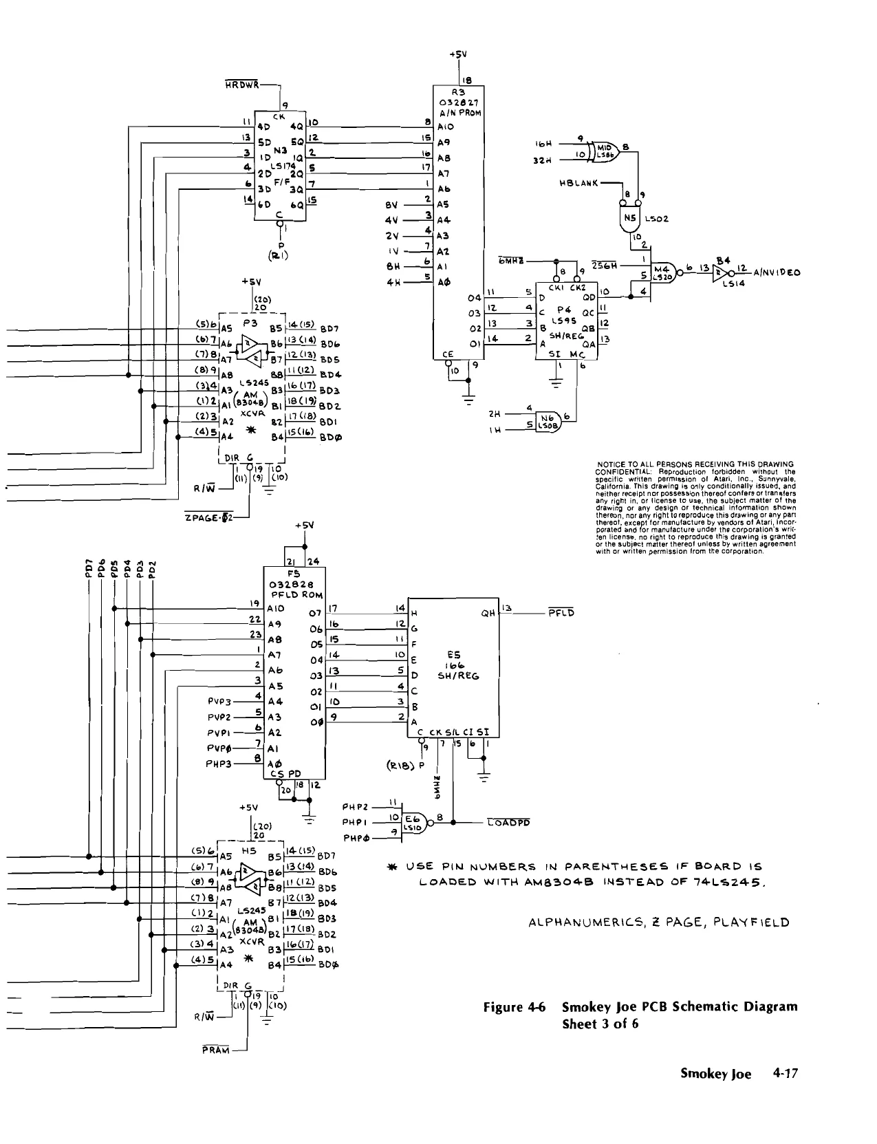
H. ALPHANUMERIC GENERATOR (See Figure 4-6, Sheet 3 of 6) Alpha and numeric characters are displayed as 16 by 16 objects, comprised of 16 lines ot 16 bits of video per line. These alphanumeric characters are stored in ROM R3 which is accessed by addressing data from RAMs N2 and P2. The microprocessor loads the alphanumeric location data into these RAMs. Specific times during the active video scan, as determined by the HRDWR signal at pin 8 of device L7, horizontal and vertical synchronization data address the alphanumeric location data stored in RAM. The RAM output data then addresses the actual video data stored in ROM R3.
Smokey Joe 4-5
Table 4-1 Microprocessor Signal Descriptions
Number Signal of Description/Function lines
| DO-D7 | 8 | These eight lines are bi-directional data bus lines. |
| A0-A15 | 16 | These sixteen lines are unilateral MPU address lines to |
supporting memory (i.e., ROMs, RAMs), and I/O.
| HALT | 1 | This input is permanently connected to a 1K-ohm pull- |
up resistor.
| RESET | 1 | This input line, when low, resets the MPU from either a |
power-down or on a QE output of the watchdog counter. During the reset sequence prior to RESET going high, the contents of the last two locations (FFFE, FFFF) in memory are loaded into the MPU program counter to point the start of a reset routine.
| IRQ | 1 | This input when low indicates an interrupt request to the |
MPU. After the MPU concludes its current sequence it will then proceed to the IRQ sequence.
| NMI | 1 | This input line while going low indicates a non-maskable |
interrupt sequence. After the MPU concludes its current sequence it will then proceed to the NMI sequence.
| DBE | 1 | This input line when high enables the MPU tri-state bus |
drivers. It is driven by the 2 clock
| 1, ©2 | 2 | Two-phase, non-overlapping MPU clock inputs. |
| TSC | 1 | This line is permanently tied to ground |
| R/iW | 1 | This output is the read and write signal line which in- |
dicates the direction of data transfers on MPU data bus.
The 4bit parallel output of the ROM is then converted into serial data by shift register P4 and summed into the “Video Out” circuit as the “A/N Video” signal.
I. PLAYFIELD GENERATOR (See Figure 4-6, Sheet 3 of 6) The playfield generator is similar in operation to the alphanumeric generator. Playfield ROM F5 contains the actual playfield video data. ROM data access is controlled by RAMs J4 and H4. As in the alphanumeric generator, the playfield location data is stored in these RAMs by the microprocessor. Then at specified times during active video scan, as determined by the PRAM
4-6 Smokey Joe signal at pin 2 of H2, the horizontal and vertical playfield position counters (E3, E4, F3 and F4) address the playfield location data stored in RAM. This data then addresses the playfield video ROM. The ROM’s parallel output data is converted into serial data by shift register E8 and summed into “video out” as the PFLD signal. J. CAB VIDEO GENERATOR (See Figure 4-6, Sheet 4 of 6) The cab video PROM (programmable read-onlymemory) P7 contains the cab video display data. This PROM specifically contains four distinct cab video rotation displays (0 degrees through 45 degrees). All 24 rota-
tions required to rotate the cab a full 360 degrees are simulated by exchanging the horizontal and vertical sync signals, controlled by the state of the INVTVH strobe to data selectors P8 and R7, and/or by inverting the horizontal and vertical sync pulses via exclusive OR gates R6, R8 and N8. The video Prom’s parallel output data is then converted to serial video data by data selector M7, and summed into the “Video Out” circuit as the “Cab Video” signal
K. TAIL VIDEO GENERATOR (See Figure 4-6, Sheet 4 of 6) The tail video ROMs J5 and L5 contain the tail video display data. The ROMs actually contain data for seven distinct rotation pictures. Signals TRO, TR1 and TR2 select the proper rotation.
These seven rotations can simulate all 24 rotations necessary to rotate the tail a full 360 degrees. This simulation is accomplished by controlli ng the up/down polarity of up-down sync counters L3, K3, L4, and K4 (via XINV and YINV). The ROM parrallel outout data is then latched (at M5) and converted to serial video data by data selector N6, and summed into the “Video Out” circuit as the “TAIL VIDEO” signal.
s L. STEERING CONTROL LOGIC (See Figure 4-6, Sheet 5 of 6) Steering (STEER 1A, 1B, 2A, 2B) information for both the cab and the tail is “looked” for by the microprocessor (C3) during the play mode. The steering PCB assembly consists of two light-emitting diodes that are optically aligned with two light-sensitive transistors. A toothed cylinder (turned by the steering wheel) is inserted between the light-emitting diodes and the transistors, and it interrupts the light from the diodes.
When the steering wheel is turned, two pulses appear at the output of the steering PCB assembly that differ in phase as illustrated in Figure 4-4. When the wheel is turned to the right, the A output pulse leads the B out: put pulse. When the wheel is turned to the left, the A output pulse lags the B output pulse. The inverse of the two pulses are applied to the D and clock inputs of the D-type flip-flops L10 and M11. The MPU recognizes that a steering maneuver has been made when a low appears on data line BD7. The MPU then looks at the data line BDO and determines from the logic level (high or low) whether the turn is left or right. Once the MPU has processed a steering maneuver, the MPU then outputs an address that is decoded by the address decoder and results in a low STEERING RESET signal. This signal resets the D-type flip-flop responsible for the STEER FLAG signal. M. HORN AND BELL GENERATOR (See Figure 4-6, Sheet 6 of 6) The horn is manually sounded by pressing the large pushbutton labeled HORN at the cab control panel.
The bell is also manually sounded by pressing another large pushbutton labeled BELL at the tail (trailer) control panel. This also occurs automatically when points are scored. The bell is disabled by the microprocessor if the game is in the “front player only” mode (trailer is controlled by computer).
N. MOTOR AND SIREN GENERATOR (See Figure 4-6, Sheet 6 of 6) The key to the motor generator is the operation of transistor Q1 in conjunction with timer B9. Timer B9 operates as an oscillator with its output frequency dependent upon the collector voltage of Q1. This voltage is the result of the base voltage selected at the MOTOR 1, 2, 3, or 4 input lines.
As the Q1 base voltage increases, so does the charging voltage at the collector across capacitor C25. This VCO control voltage sets the VCO circuit at a frequency selected by the buffered data lines; the voltage is adjustable by setting pot R27. The VCO output is divided into two separate frequencies by the divide-bytwelve device A9, and is then summed by resistors R73 and R74. This produces a realistic motor sound as the player shifts gears.
The siren generator is similar to the motor generator. The control voltage to the VCO is generated by voltage levels present at resistors R45, R46, R47, R48 that drives voltage follower E9. The output of E9 is the control voltage that controls the output frequency of timer B9.
- BANG AND SCREECH GENERATOR (See Figure 4-6, Sheet 6 of 6) The heart of the bang and screech generator is the noise generator comprised of 8-bit shift registers B8, C8. These two devices are connected in a manner to produce random noise at the QH (pin 13) output of B8.
The bang is the result of data {BD4-BD7) from the microcomputer; the data is used to gate varying amounts of random noise through to the audio amplifier. Starting with binary data code 1111, then radidly stepping the data code down to 0000 results in gating noise from noise generator B8, C8 through a
Smokey Joe 4-7
resistive value of 550 ohms (R34, R35, R36, R37 in parallel) to 8.2K ohms for a data code of 0001, and infinity for a data code of 0000. The result is an envelope from full “on” to full “off”.
The screech sound is produced by processing the output of the random noise generator with a type of hysterisis feedback loop, comprised of Schmidt-trigger inverter B4 (74LS14). This processed noise is gated to the audio summing network each time SKIDSND goes low and clears the B6 flip-flop.
48 Smokey Joe P. AUDIO OUTPUT (See Figure 4-6, Sheet 6 of 6) All the processed sounds (i.e. siren, motor, horn) are summed at the inverting input of op-amp E9. The output of E9 is then sent off the main PCB to be amplified by the “Single Audio Amplifier PCB.” Q. SINGLE AUDIO AMPLIFIER (See Figure 4-9) The single audio amplifier for Smokey Joe is the -01 version assembly which uses only one of the audio amplifier circuits. The audio output (pin 18 of the Smokey Joe PCB) from op-amp £9 is amplified and matched to an 8-ohm speaker. The audio level (volume) is adjustable by rotating the R2 potentiometer located on the Single Audio Amplifier PCB.
This page carries no recoverable text. It is a drawing or a photograph. See the original scan.
ae 7 sin rion | (2 3 | FoR POWER SUPPLY con[on |) sewemanee of os SEE 007197-01 _9R| ge
of 3? oe PowER SWITCH
84 gu es 432 sul oe alafal a> rete bette
44- POS EDGE CONNECTOR
- SV CT GRD 7 REN» 1e.5V CT GRD rgiscS +10V_UNREG 2 pass +10V UNREG te{avex | _ 3
¢
| COIN TNO. | 4 (OR | \ |
CON 2N.0. ok STEER IA s pwiey STEER IB ew «fe | 7 Foncorr sul Le lee
| START LAMP 3 [wn [WY | 7 | 4 | i |
START LAMP 1 [@ [os So TRACK SEL LAMP] 7 }SK/W eal ry
| GAS NO. | 5 SulBK | suiexf | [1 )su | |
| u | t | BK | 2 [ex |
| SLAM NO. | uw ay | GN | 3 |6N |
| TEST | ™ | | |
START INO. [iz peer
N START 3 NO, [ia bYOR
°
TRACK SEL ND, [R }w/SY
s +5V [ie |® = VIDEO OUT fia Vibes Gap u pew AUDIO OUT ie [WBN HORN NO. v we COIN CNTR 19 [oNR Lockout coi [w feNex —_{ __ 20 t _
| | x | | i, | T | |
| 2 | Ty | ey | |
| GRD (Sw.com) |22 | & | > | a S| el ala |
| AUDIO GRD | = a | 15% 13 %2 8 “10 9 eel oe 4 &a, °5 cet |
FOR COIN DOOR SCHEMATIC, SEE O30401-01
4-10 Smokey Joe
| lex
| aay | 7 len | 9 | | roaresceut |
| out | i. | LIGHT |
[2 fu eo ons
| vf | ot | oe] | ax |
WIGN, 2 od o® ol [> 38 59 o®
| o! | aK | MONITOR |
WSU ot t ouT
| 3 | [we | + | wi | te | aN |
, gy ) rp] | wiex SPEAKER i
+ =
; 7 x ry AUDIO BD
| al | 3 | &| |
| oh sh ye low
| 4 | ob | 8 | glo |
| of | 0 | 9 |
vot j
ye a3 8
[ureatock sl [wreavoce su] 0% 8 0% 8k
_ a -
+ |
CAB START wl we de 5 1
ile eft Ste orf fax 4
TRAILER START wil f+ le rs
+ 7 | f w | $e
NOTICE TO ALL PERSONS RECEIVING THIS DRAWING CONFIDENTIAL: Reproduction’ forbidden without the Specitle written pe California
this drawing or any part wengors of Aan ner 10 right to reproduce this drawing is grant ‘or the subject matter mereo! unless by written agreement ‘with oF written permission from the corporation:
Figure 45 Smokey Joe Harness Schematic Diagram
Smokey Joe 4-11
This page reads as a drawing: its text was drawn rather than typeset, and comes out in fragments. See the original scan.
(ee) (Rel) ° P
| 3 |4 is | F | 2 | is | |e is |
jae epee ms De —————er e 10] NIO. Na is ET isis CO ck BIN CNTR @A a8 aC ad ¢ ie fia fiz be @en
2H au 6H tow 32H eau eH
Tee >—+—25eH etn
FIF
| Stay | 4 | 2 | 3a |
33 30) a a|u (wey —]ae soft 2|* Re si
| eAy | as | 22/2 | S|, | zat |
tov —Saeey Peas ale —
| av | —4as ye ill | 1o 2 — |
av —Tardg Ae w—iar” ia sy Slag cel Ce2 cK_¢ e ye 9 a ° @s)
HOYNG
\
- IMME
(e30) ° du
| + 12 | 14] | * | 0 |
‘
- iss: 7 58 2 3]e Usiog rR rie emnz——2lex ay? TMA c ys stecex —J ° (230) K7 2h —"[So!2 78
VBUANK
NOTICE TO ALL PERSONS RECEIVING THIS DRAWING CONFIDENTIAL, Reproduction forbidden without the specitic writes, permission of Alar, inc... Sunnyvale Gaiifornia’ This drawing is only conditior paither receipt nor possession tnereo! cor any Srawing or any design or tec hereon. nor any rignt to reproduce this deawing or any part tnereet, except for manufacture by vendors of Atari Incorporated and for mariutacture under the corporation's wri rn igense, no night to reprod. forthe subject matter ther wwatn oF wr or transfers matter of the
SYNC, POWER
Figure 46 Smokey Joe PCB Schematic Diagram Sheet 1 of 6
Smokey Joe 4-13
This page reads as a drawing: its text was drawn rather than typeset, and comes out in fragments. See the original scan.
| a | +O | +Sv | +S |
ev 4
| ae | ul | — | - | ||
| 8 | a | BUF sco) | la |e | fas Jew | das la |
bas
| ‘FATURST (140) | Fi | D | cl. |
oszg2s [032824 | osza2s VOOR (1400) ies ig {Pani ratslenag Roma] paae tom | Orbe dams
| FPSB (1460) | We | i“ |
a FRIBENB (1440) saa] -——|a
| ce | CARSRINB (1420) | Aa | 4 | |
| use2, | MOTOREN (400) | San | al | |
| , | Decooe | one | —2 | 7 |
| BAIo | sas | —> | As |
at 33
| Ww | ri Ke | it | -WATTROOGRESET (1060) | BAR | 8 | Ay |
| BRB | Se | ‘aly | gaz | —* | ar | |
| 3 | aa | aL |
a7 lc BRROWOFF (100) A
| baw | 14, | Bag | — | ad |
| ‘S| | 7 | 7 | ||
| = | iN | STEER RESET (1 | ||
| STee RF ESET | (1040) | be | ie | ee |
| TREROT (1080) | 8 | os |
SKIDRESET (1060) bat a -——oa
| (ew | ipe— TRASRRESET (1040) | ps2 | cles |
| e | pe | 1 P*—- PHPLOAD (ioz0) | |
| L842 | 1 | PYPLOAB | (1000: |
f 10
8 09 D358
| K Ree | vo] BF | Be |
@ al cx 4 ©
| - | | | | | SP ee 41 |
FORT —_—
| p08 | — ware | “02 VERSION | ||||
| u | ae | 450 | 4sy | sy | SY | ayy |
i
| Te 4 | Pal | KL | ue | Mt | 32 | Kz | 2 | M2 | NOTICE TO ALL FERONS' REC ING THle DAA. | ||
| = | 93215 | o3zeie| 032917 | 032818] 032819 | 032820/03262: [oszeze, | SONFIDENTIAN Remedistion, laterite ale, | |||||||||
| = | AoE PxoM| BROT PROM | PROG Prou| PROG PROM PADS PROM] PROG PAou| paoG KOM | PADS PRM) | —PeRITIC | writen, PermIesor | Ol Mull, Ne. Muses | |||||||
| aie | al | 3 M56) | 2 mse) | | M58) | T'S Msg] | 3 USB | 2 LSB) | 1 LSB] | 58) | Felner | veceipt nor possession heveol conters ar ranaiers |
| eae | eT | ao | Gey ght nor Reense to use, tre subject matter of the | ||||||||
| Peed | x | el | toad | ‘drawing or any design or technical information shown | |||||||
| pag | —I¢ | fae | thereod. nor any rightso reproduce this drawing or any part | ||||||||
| Bar | — | = | lay | thereo!’ except formanviacture by vendors of Atari, ncor | |||||||
| a | Re | Rechcense, ne ight to seproduce this Sawing Vs granted | |||||||||
| el | ra | aa | with or written permission trom the corporation, |
eas —4 aa BAL nm
| Lad | u | of |
°7 D3.
| De | —e | 1252 |
| ps | —2 | 3B |
| Loar) | a | Oe |
ice ce rt if 7
| (Oma | - | = |
Rowe a omit +
| Rome | + | — |
MICROPROCESSOR, MEMORY ~Ol VERSION 4% USE PIN NUMBERS IN PARENTHESES IF BOARD CONTAINS AMS304B INSTEAD OF 74.5245.
Figure 46 Smokey Joe PCB Schematic Diagram Sheet 2 of 6
Smokey Joe 4-15
This page reads as a drawing: its text was drawn rather than typeset, and comes out in fragments. See the original scan.
This page is a drawing, shown as the original scan.
This page reads as a drawing: its text was drawn rather than typeset, and comes out in fragments. See the original scan.
NOTICE TO ALL PERSONS RECEIVING THIS DRAWING CONFIDENTIAL” Reproduction’ forbidden without the Specific waltan permission of Atari, Inc.” Sunnyvale California’ This drawing 18 only conditionally sued, and nether receipt nor possession thereo! conte’s or transfers any right in, oF license to use, the subject matter of the Grawing oF any design or technical information shown {eteon, or any right te reroduce this grawing or any pat thereof except for manulacture by vendors of Alar, incor porated and for manutacture under the corporation's wt. {en incense. no right 1o reproduce thus drawing 1s granted forthe subject matter thevea! Unless by writes agreement ‘wan oF written permission from the corporation
| crasdcope | ——? | 10 |
$ 4
| me) | ,2 | 8 |
- 850 rs “ > = x - PFLOWIDED Fr 49 v VBLANK “2 cua
| o | 2 | : |
ie ’
| SH | ng | new | |||
| vet | a | al | u | ||
| ri | a | « | Ap | al | Pewnoo |
| cd | 13)s20) | =a | |||
| 3] | usis3 | a | if | iste | sla |
| 1 | ‘on | 9 | an | caer |
Ole BATA Se face A B
| ze me | CABNIDEO | BLANK: |
2 oN whee. ‘Baca wo A Je [it
Lens
| cnovibto | TFB 3 | caw | arate |
TAILVIDES *
(@20) ° 5 PFLDVIDEO — = pect $ 2 4 _ P wa? (37 ey Ye" gl8 SABE TAIL Ad Ts
| 7 | PeLDVIDED | la |
t Peer
| @20) | FLasu | [> | ||||
| PEWNDO- | 2 $00, | ~ | ||||
| ax | A{NviDED | = | a | CRRSWRESET- | pleze) | = |
| | | VBUANR, | Se | du | |||
| week | PD | ee | ? | |||
| 910 ju | atte | 4a] | 1. | — | ||
| afe ee | 4 | Te | a | CRRSAIN | ||
| De | 5 | cRrasucone—“y | 13) | r509 | ||
| als, | v2 | raeviveo | sk ele |
at wp
| os | Me | PFLDVIDED | 3 |
sisi an [So
| ISloq DATA | $8 | emnz— | cage tar, ——{2°8) |
Pilea ps MUX
| Fee | Js | F | Tek |
| les | sjerarer | |, | |
| $33] | TORDPD —*qre | MRO | P(e) |
| i | peed | SKIDIN |
Peer Me Ragucope — SKIDLODE
- sKipcove
Figure 46 Smokey Joe PCB Schematic Diagram Sheet 4 of 6
Smokey Joe 4-19
+s) +8V¥ 9 de R18 SRT s 10K 910K wn? STEER FLAGI «1800) une
| sreerie [Ee | ah | crane 2 (1801) |
cre spare [K
| q | STEER FLAG | | L802) | |
| a | STEER RESET | STEER FLAG2 | (go) |
+8y
| (a0 | SRST | cia06) |
| eal | ° | TRESER [x LL8OD |
at 2? ale
| reer i [5] | a Dol2 | D8 | STEER DIRECTION) |
| LSié | by | ) | |
| cas, | tH) gta 8 | comano, [p | “808! | + |
ol cir res
| = | y | con No. [4] “80% | + |
(ete) e(2T6) bro e ]6 ee Dal STEER FLAG 2 uo
| —_ | were | 29% |
| steer 26 [F] | «8 | 10% |
chr Ey (1800) spare [UC \_ STEER RESET I os fie seen
| #0 | STEER DIRECTION | | (1802) |
(er) STEER DIRECTION 2 ©1803) “8o4a)
| 1S | ; | a | cigos) |
| loK | 4 | acam [xo | 7 |
| un | 2 | ToT | 4806) |
e [2 s
| steer 24 [o | D | a | STEER DIRECTION 2 | met fr ii20 | J |
isa = Cae — Ot
| = | +5v | .—+—+ |
ret | RIOT SRIOSS ios, 8-P0s NOK FIOK P1OK = IDie sw une 2L 18 ee le
| . | xtend 921 | le |
(aso)
| aranTt [apes | options | 2 |
START? [P oT
| is | 41802) | wpe spe | pus | 1 | —* |
| STARTS list | TIME | 8 | + |
_ 1803)
| TRACK SEL TR | , | S251 | XTEND | Ia J |
| spare | ig LUS2* | D4 DATA | rn | in | |
| aum | 8.05) | LJ |
cramner [5 82%? = saxenon bal ceo” +5¥ 9-9 —________
es) pio Sei | 4-P0s' 1OK C7 10K [DIP Sw | con Move | -SLo-~o 14 el EY COIN MoDE 2 6
| tH | lz | i |
ee 4
4-20 Smokey Joe
RBS > ROT S 2B—
| LOK | S1OK | Si0K |
NOTICE TO ALL PERSONS RECEIVING THIS DRAWING. CONFIDENTIAL “Reproduction” lorbidden without The Specilic writien permission of Alar, tne. Sunnyvale. Gattornia This drawing 's only conditionally issued, and either weceipt nar possession theres! conters or ransters ‘ny right on, oF license To use, the subject maltet of ine Srawing oF any design or technical information. shown thereon, nor any night to reproduce this Grawing o¢ any part Inereot except Yor manulacture by vendors of Atar incor porated and tor manulacture unde the corporation's wet en license, no right 19 vepreduce this drawing Is granted forthe subject matter thereo! uniess oy witten agreement wun oF written permission from the corporation
+
TI uu ow
| uo | | | c |
use t ATTY 9 cow couNTER : ' Bh ans. 2 Jeske Ly Lsi4 IN4901
E
b®&—_ soe
+5
| 4 | '5lyq DATA | vor | +5V | |||
| 16 | SEL/ | | | ||||
| + | ps | ‘ux | it | lao | 201 | ; |
rar BE — 4 -$ StaRT LAMP:
| 3 | ralZ | foo. | |||||
| Bro——S}1D | sa . | Reo | wl | ||||
| spr | 4D | 4Q| | AK | DR — MH -$START Lame a | |||
| all. | Kio | [5 | heey | ||||
| i | Be | 20 | FLASH | 230 | hb | ' | |
| iNT | aps | 3 ne] | {F} —- -$raack secect Lame | ||||
| oer | spa | —3)sp"'sa}!2 | —_arraact | oe | I | ||
| Zid Sai04 | $2102 | BAL | -BDS | a sp | gal'9 | ¥ | NH} — We -/ staat Lame 3 |
| 10K | Si0K | 10K | |, | Nop | wot | ad | |
| 1G | 307 | —4,> | a'® — settour | ein. | |||
| flo | a | arraact——3) | 5012 __ | aTTRRET | |||
| t | sic, FIO | v | 10 | Lso4 |
y
| + | Mice | id | ® |
| Pipe) | (R16) | vow |
10 |- 5 oaral co DATA LAM. @ Lockout
| woe aoe | arrRact 9 | 255 | ~ | f+ | + Pita |
| act | My | Bol | 83 | ob | Ly |
| 22 | MIJE3300 | IN@OO) |
Baca 26 A ig ie oF _ Bag
Ri2 Seid 10K 10K eC ee
| 4 | ol | abs |
4! Is BD4 21 SS 13 aps les 1 ' ‘ " ae Figure 46 Smokey Joe PCB Schema “-% Sheet 5 of 6
onr—
Smokey Joe 4-21
This page reads as a drawing: its text was drawn rather than typeset, and comes out in fragments. See the original scan.
+5N
Rm MOTOR | ——WA—# R27 SV
- iM ATTRACT ——o—
MoToR2 ——\WA—# +
Dis Zhi 87 Old MOTORS TH ese
ITR TIMER ev MoTor TORS 20K ANS 644 3
+]ee cas Cie
SIREN!
SIRENZ
SIRENS
SIRENG f Ol, TS os ieet
+5N
NOTICE TO ALL PERSONS RECEIVING THIS DRAWING CONFIDENTIAL: Reproduction’ forbidden. without the specitc written, permission of tar. Inc.” Sunnyvale, California” Ths drawing 18 only conditionally issued, and Neither receipt nor possession thereot confers or ransiers any right in, of license to use, the subject matter of Ine Grawing oF any design or technical information snown tnereoa, nor any right to reproduce this drawing oF any part thereo!. except for manufacture by vendors of Atari incor porated and for manuacture under the corporation's writ {en license, no right to reproduce this drawing is granted fortne subject matter hereot unless by writien agreement ‘wun or watien permission irom the corporation,
AUDIO, AUDIO OUT Reo +sv
ATTRACT —
SIREN
+5y MOTOR
18] AUDIO ouT Pal Ten 820 he
z5q C34 ¥TNDPLY —~WA—4E4 47K 22
RSS Cx HoRN WK 22
aeLL ————_—__4
R53 cas SCREECH ——Ww— 33K (.2t
R56 C33 BANG —-VWW-E# ioK 22
MOTOR—~WA——# 2K
eee cst SIREN SOK 22, 2 | Audio GND)
Figure 46 Smokey Joe PCB Schematic Diagram Sheet 6 of 6
Smokey Joe 4-23
SLAM SWITCH
ON 6
BU Buy .. BU BU 02
R | 63 on/R | 94 BKIOR| 45 OR/BK| Ob iS POS MOLEX
OR 1] PLUG + MALE
BKIY | (68) TERMINALS
COIN
COIN SWITCH
COUNTER #1
(RIGHT)
COIN *2. CLEFT)
COIN *1 CRIGHT) FRONT VIEW OF COIN DOOR
Figure 4-7 Coin Door Schematic 030401-01 4-24 Smokey Joe
This page carries no recoverable text. It is a drawing or a photograph. See the original scan.
aof Aayouws = 97-7 ANd NI DV a4 uw) a) LO NGI nat ud A Sot AINA yy NMOS 12 o : Wes ow S91 Asi | Ne | POT 3¢ yo BOVLION NOt};
Ad =! LS\L-2h WAaWwYOASNVYL Shunvse Sts SHInI9Oae SOs I Bea GD
PCB A0OL555-01
a (ex PLCs) | | 2,000.4 | @15V
se are MR750 \ e-|l-— r |
is RY
(e} in
TP TP INTERLOCK SWITCH Cra Wt} Ww BK | x | BK
Bk Pot BK
GW
- ON/OFF | SWITCH
Figure 4-8 Type B Power Supply Schematic Diagram 007197-01 Cc
Smokey Joe 4-27
Ri2 INPOT £ [4 OOK R2 loK
- ¢R2 CRB CRI CRIO CRU CRIZ Zsvac|s } x IN4ZO0O! x» S PL 7Lhes T 2200n
Z25VAC =
NOTICE TO ALL PERSONS RECEIVING THIS DRAWING CONFIDENTIAL” Reproduction, foriiden, witout ne mission ol Alar, Inc. Sunny eno [3 {7[9} 4
ticense, 00 ght 1 reptduce tn drawing ubjec reat uniess by writ ‘tno: witen'pertiosion tom ihe corporaion
test [eo/-—-
Figure 4-9 Single Audio Amplifier Schematic Diagram
4-28 Smokey Joe
ILLUSTRATED PARTS CATALOG
The purpose of this chapter is to provide you with the necessary information for ordering replacement parts for the Smokey Joe game.
When ordering parts trom your distributor, give the part number, part name, applicable figure number of this catalog, and the serial number of your Fire Truck game. This will help to avoid confusion and mistakes in your order. We hope the results will be less downtime and more profit from your game.
Smokey Joe
ARER
| TEMS: NOT SHOWN: ©) AB
iS) mo | 8 18 52) \C eEQD
e 3 4 REQ'O 4B) seaca : on (56.4 Crap
- ne 2a0 a eed
- tga, ‘a 7
SECTION AA
Figure 5-1 = Ea ; : 2 A Vv a oe fr 33 Ft i al 4 FR eA |
Smokey Joe 5-2
A ATARI’ Figure 5-1 final in Assembly Item| Part Number | Qty. Description 1 4032890-02 1 | Assembly, Cabinet W/Graphics 2 A032888-01 1 Control Panel W/Graphics 3 4009083-01 1 Coin Door 4a A008845-01, a Single Foot Pedal W/Harness 5 A006449-01 1 On-Off switch 6 A007902-01, 1 cash Sox 7 A008766-01 1 . TV. Tray 8 A005430-01 1 " Display 9 A033016-01 1 " Power Cord io} a007197-01 1 " Power Supply Type a1} a007299-01 1 * Rear Door W/Lock 13] a030867-01 1 R-P. Box Shield Assy 1a] a030928-01 1 " R.P. Shield P.c.8, 15] a030926-01 1 " P.C. Board (FIRETRUCK) is} a009424~xx 1 " Shipping Container 7 005419-01 1 | criti, speaker 18 0016 38-01 2 | Bracket, Panel mtg 19 009268-02 2 Switch Mtg 20 008870-01 1 Coin Box 21 006319-03 1 | Decal, Copyright 22 008767-61 1 | Bezel, Cardboard 23 008759-02 1 | Plex, Monitor (Smoke) 24 032895-01 1 | Plex, Monitor W/Graphics 25 003053-01 1 | Retainer, Upper Plex 26 908764-01 1 "" Plex 27 032894-01 1 | Plex Display W/Graphics 28 905233-01 1 | seal Rear Door 29 (007103-01 1 | Cover, on-off switen 30 006305~01 1 | Bag, Printed Poly a sT-116 1 | self Test Chart 32 M-116 1 | Tech. Manual § Illustrated Parts cat. 33 81-702 2 | TIP-N-TELL Indicator 34 78-24007 4 | Cable Tie, Heat Stablizea 35, 75-935 4 | Wing wut, #4-20 36 75-990505S 4 | Mut, Lock, Shallow Pattern #4-20 7 78-25001 1 | Tie Wrap, Screw Down 38 73-7015 4 | Pop Rivet, 3/16 0.D. x -68" Lg,= ort 39, 75-0158. 12 | Washer, Flat, &
Item |__Part Number _| Qty. Description 40 75-045 6 | Washer, split-Lock 4" 41 75-9155, a | nut, Hex, #-20 42 75-55168 4 | polt, Carriage #4-20 x 1.00" Lg, B1k 43 72-6610 a1 | Sexew, Sht. Met., Pan Hd, Phil, #6 x 5/8 Lo 4a 72-6812 12 ” " wow" 48 x 3/4 bg 45 66-002 2 | Switch, Ac Power Interlock 46 75-5532N 2 | Bolt, Carriage, #4-20 x 2.00 Lg 47 75-83090006 6 | Well-wut, Blind Hole Fastener, #10-32 4a 82-8016 6 | Serew, Button Ha, Socket Cap, #10-32 x 1.00" Lg. 43 92-1824 8 | Serew, Hood, Flat Ha, Phil, #8 x 1.50" Lg. 50 | A032839-02 1 | Assembly Main Harness
- 72-6808 1 + Pan Wa Phil #8 x 4" Lg 52 72-6608 12 2 * fe x kM Lg 53 46-201202 2 | Fuses, Slow Acting (2 AMP) sa | a009574-01 1 | Assembly, Audio-AMP PCB 55 72-14068 4 | screw, Mach., #4-40 x 3/8" Lg.
Smokey Joe
NOTICE TO ALL PERSONS RECEIVING THIS DRAWING CONFIDENTIAL’ Reproduction forbidden without the Specitic written permission of Alan, Inc.” Sunnyvale, Bivtornia’ This drawing 12 only conditionally issued, and srrecelpt nor possession thereat contars or ‘ny nght in, or license 10 use, the subject mater of the Grawing of any design or technical information. shown thereon, nor any ight to produce this drawing or any part thereat except tormanutacture by vendors of At Ineo porated and for manufacture under ine corporation's wit. fen license, no right to reproduce this drawing is granted ‘or the subject mater thereo! unless by written agreement win oF written permission from the corporation.
Figure 5-2. TV Tray Assembly A008766-01 Cc
5-4 Smokey Joe
Figure 5-2. TV Tray Assembly Parts List
ATARI’
Part Number Description
008755-01 T.V. Tray 72-6812 Screws, Self-Tapping, #8 x 3/4 Phil. Pan Hd. 005594 Monitor Tie Down 90-032 T.V. Motorola 23" (M7000-155)
© A drainer communications Company
Smokey Joe 5-5
NOTICE 70 ALL PERSONS RECEIVING THIS ORAWING CONFIDENTIAL: Fi
nO right 10 feproduce this drawing ts granted forthe subject matter thereo! uniess by written agreement ‘with of written permission trom the corporation
Figure 5-3 Control Panel Assembly A032888-01 B
5-6 Smokey Joe Z, BU (N.o.) wily
W/O@(N.C.) BK (NO) (6) BK / ZED (N.o.) () 2 ean
ATARI Figure 5-3 Control Panel Assembly Parts List
Description
tw) ‘A Warner Communications Company
| Item | Part Number | Qty. | |
| 1 | A000598-03 | 1 | |
| 2 | 032892-01 | 1 | |
| 3 | 032893-01 | 1 | |
| 4 | 85~22F112 | 6 | |
| 5 | 75-040 | 6 | |
| 6 | A009338-01 | 1 | |
| 7 | 000567 | 1 | Bow Washer |
| 8 | A032856-01 | 1 | |
| 9 | 001856-01 | 3 | |
| 10 | 62-002 | 3 | |
| ll | 72-6610 | 2 | |
| 12 | 75-5524B | 4 | |
| 13 | 75-015S | 4 | |
| 14 | 75-915S | 4 | |
| 15 | 75-045 | 4 |
Steering Wheel Assy Control Panel W/Graphics Control Panel Back-Up Mach. Screw, #10-24 x 3/4" Lg Pan Hd, Phil.Type "F" Washer, Split-Lock, #10 Start Button Assy
Control Panel Harness Assy Bezel, Switch Switch, Licon (LED) Screw, SM., Pan Hd, Phil, #6 x 5/8" Lg Bolt, Carriage, #4-20 x 14s" Lg, Blk Washer, Flat, 4" Nut, Hex, #%-20 Washer, Split-Lock, #%~20
Smokey Joe 5-7
CD) ! 244 © 2 PLCS (21) :
- 2 PLCS
- 2 PLCS
- 2 PLCS 2 PLCS @2)
° ©
@ 2 : BET ag Gi) 2 Pics
4 PLCS Qi)
YEL YEL/BK BK/YEL BKJOR (2)4 PLCS
NOTICE TO ALL PERSONS RECEIVING THIS CRAWING CONFIDENTIAL. Reproduction” forbidden specific written permission of Alar Inc. SBiiornia This arowing is ony conditionally ssued and {ceipt nor possession thereof confers or translers or iconsa 1
fen icense, no right to reproduce tis drawing s granted ‘rine subject matter thereo! Uniess by written agreement ‘with oF written permission from the corporation,
Figure 5-4 Coin Door Assembly A009083-01 Cc
5-8 Smokey Joe
Figure 5-4 Coin Door Assembly Parts List
A007637-01 Front Bezel Assy. - Used only or
| A007637-02 | Front Bezel Assy. | Used only | |
| A007637-03 | Front Bezel Assy. | Used only | |
| A007637-04 | Front Bezel Assy. | Used only | |
| A007637-05 | ; | Front Bezel Assy. | Used only |
| A007637-06 | Front Pezel Assy. | Used only |
A007637-07 Front Bezel Assy. - Used only See Figure 5-14 75-9165 Nut 6-32 A030362-01 Coin Lock-Out Assembly See Figure 5-15 007640-01 Coin Switch Assembly See Figure 5-16 A002465-01 Coin Counter Assembly 004320-01 Coin Door Weldment 004341-01 Secondary Coin Chute 004344-01 Key Loop 004340-01 Spring-Return 004337-01 Bracket, Wire Form 004338-01 Lock+ Out, Wire Form, R.H. 004336-01 Lock-Out, Wire Form, L.H. 004326-01 Button, Scavenger 75-046 Lock Washer, #6 006904-01 Spacer 007359-01 Lamp Socket 70-11-47 Lamp 73-3008 Retaining "C" Ring, Truarc #5103-25 75-9914001 Self-Threading Not, Timmerman #SR188006 75-026S Washer #6 75-00516 Kepnut, Style 842, Stl., 6-32 008629-01 y Spring 71-2118 Lock Assembly, Hudson Lock 71-1225CU Coin Mechanism for American Quarter only 71-125FB Coin Mechanism for Belgian 5 Francs Only 71-1205FF Coin Mechanism for German Mark only 71-1201MG Coin Mechanism for Swedish Krona Only 71-1201KS Coin Mechanism for Japanese 100 Yen Only 71-1210PE Coin Mechanism for English 10 Pence Only 71-1220CA Coin Mechanism for Australian 20-Cent Piece only 007753-01 Plate, Anti-Probe A007638-01 Switch Assembly - Slam A006921-01 Harness Assembly © 4 Warner Communications Company
Smokey Joe 5-9
- 2nc8
NOTICE TO ALL PERSONS RECEIVING THIS DRAWING. CONFIDENTIAL. ‘Reproduction forbiagen without the Specie wntten, permrasion of Atari, ine.” Sunnyvale ‘This drawing is only conditionally issued, and Feitherrecelbt nor possession here! confers a: ransters ny ngntin.or lcense to use, tne subrect matter of Me Sri" any dastgn 1 echlelnfornat'on shown thereon, or any Aghtto reproduce ths drawing or any pat Inereo! except focmanulacture by vendors of Afar, Inco Poveted and for manufacture uncer the corporation's wit Fenticense, no righ to reproduce ths drawing vs granted or the subject matter ihereor unioss by written agieement wth of wetten permission Irom the corporation,
Figure 5-5 Front Bezel Assembly A007637-01 thru -07
5-10 Smokey Joe 2Aacs
Figure 5-5 Front Bezel Assembly Parts List
ATARI
[item Part Number Description
| 1 | 004328-01 | Bezel |
| 2 | See Below | Ring |
| 3 | 004331-01 | Coin Shield |
| 4 | 004332-01 | Primary Coin Chute |
| 5 | 004327-01 | Bearing, Scavenger Button |
| 6 | 004329-01 | Clamp, Price Plate |
| 7 | See Below | Price Plate |
| 8 | 73-3009 | Retaining "C" Ring, Truarc #5103-37 |
| 9 | 72-1604S | Mach. Scr., 6-32 x &* Lg. Pan Hd., Phil |
| 10 | 75-046 | Washer, #6, Split-Lock |
| il | 75-9914001 | Self-Threading Nut, Tinnerman #SR188006 |
[OAsH Nol =TEM 2 STEM 7 [DENOMINATION] =o: [Sousso-o1 [sousGs-ci | e5¢ To2 [Co4ss0-O1 [cousts-oe | SFR =os [669153 =) [Oo4sts-04 [1 OM =Oy [Sousso-o1 [SoNsIs-o8 [1 KR TOS [S095 20-1 |OOGEIS-05 | 1ICOY =6G_ [SOTTSE=61 [OO4S8S-52] 10 F COTMTS2 -S1 JOS 4343-07 [20¢ AUST
© 4 warner Communications Company
Smokey Joe 5-11
3! O80 eee’ Benes Lise 2
15e (2er) 2 PLACES
NOTES DIMENSIONS SHOWN ARE O'S Eq D.70 INTERCHANGE 8 REPLACE EELAY WITH EXISTING EQUPMENT WW FIELD AND PRODUCTION. BEAU 4 DEGLRE ALL SHARE CORNERS DIMENSIONS TAKEN FROM TooveD Paer, ONENSIONS WITH (¥) Aes SPECIFIED BINS REQUKED IN TOOLING BY ENEENELENG TO WAVE PART |WTER CHANGE W/ Onion BR YOUT Parr. COWL DATA 10VDC +2 , Som ees, CURCENT 200 me May. S MPRICOW wach, INC. (vendor) www, RaDtye~
Buy com Paw RovIes2-01
be— 2.09 —— >} joe 4 288 some Duane on Ter L \ 3
NOTICE TO ALL PERSONS RECEIVING THIS DRAWING.
ing or any part except tor manutac ure By vendors of Atari, ricOr porated and for manulacture under tne corporation's wait. fen icense, no night to reproduce this crawing is granted Or the subject matte: thereat unless by written agreement ‘woin oF wetten permission from the corporation,
Detail of Relay Coil (A007639-01)
VOLTAGE CO\L DATA lIOvoC ED
SO CURRENIT | ZOOmq MAX
Figure 5-6 Coin Lockout Assembly A030362-01 A
5-12 Smokey Joe
epics NOTICE TO ALL PERSONS RECEIVING THIS ORAWING CONFIDENTIAL’ Reproduction forbiagen wiincul ihe wotten permission of Atari, Inc, Sunnyval ia" Ths dfawing te only conditionally Issued, Iner recelpt nor possession inereot contersor transters. any right so, oF licens to use, the subject matter of the Srawing or ‘any design cr technical informaiton shown thereon, nor any rigntto:eproduce tnis drawing or any part tesco! except Yor manulacture by vendors of Atal ncor porated and for manutacture under ine corporation's wr i fo righ! to reproduce thys drawing is granted ‘othe subject mailer theraal unless by written agreement wan oF written permission from the corporation
PART NO. DESCRIPTION QTY]
JOOSS52-OT SWITCH ATG PLATE
i244 16 [SuTCH GON C5GS-3 fr2-un al2
loosa2H-ol \ SCR, MS 4-40 HLOEE TAPE] 2
i WIREFORM CHERRY
Fi igure 5-7 Coin Switch Assembly A007640-01 D
Smokey Joe 5-13
NOTICE TO ALL PERSONS RECEIVING THIS DRAWING CONFIDENTIAL. Reproduction forbidden without the Specitic written permission of Altar, Inc, Sunnyvale, California’ ThIs arawing is only conditionally issued, and either receipt nor possession thereo! conters or transiers
fen license, no right to reproduce this drawing is granted orthe subject matter hereo! uniess by written agreement ‘sith or written permission trom the corporation,
© esoe0l)
Figure 5-8 Type B Power Supply Assembly A007197-01 J
5-14 Smokey Joe NOTES:
FUSES WILL BE LISTED ON THE FINAL ASSEMBLY PAGTS LIST OF EACH INDIVIOUAL GAME.
- SEE 001195-01 FoR POWER suUPPLY SCHEMATIC (TYPE 8)
Figure 5-8 Type B Power Supply Assembly A Parts List ATARI’
| Item | Part Number | Qty. | Description | |||||
| 1 | 009575-01 | 1 | P.C. Board | |||||
| 2 | 10-51P0 | 1 | Res, Carbon, 5%, 1/4W, 1 | Ohm | R3 | |||
| 3 | 10-5390 | 1 | 7 | = | . | "39 | " | RG |
| 4 | 11-52P7 | 1 | " | " | "1/2W, 2.7) " | R4 | ||
| 5 | 11-5121 | 1 | " | " | " | “120 " | RS | |
| 6 | 19-316103 | 1 | trimpot, 10K Ohm | R2 | ||||||
| 7 | 24-250106 | 1 | Cap, Electrolytic, 25V, l0uf | C12 | ||||
| 8 | 24-250477 | 1 | " | " | "— 470u£ | C2 | ||
| 9 | 24-250108 | 1 | " | " | " 1000uf | cl | ||
| 10 | 24-250228 | 1 | " | " | “ 2200uf | cS | |||
| 11 | 27-250103 | 1 | "Ceramic, | " -Oluf | C3 | ||||
| 12 | 27-250104 | 2 | " | “ luf | c4,11 | ||||
| 13 | 31-MR75O | 2 | Diode, MR750 | CRL,2 | |||||
| 14 | 31-1N4001 | 5 | " | 1N4001 | CR8-12 | ||||
| 15 | 37-TDA2002V | 1 | Audio Amp, TDA2002V | ul | |||||
| 16 | 69-004 | 1 | Switch, Slide | Ssw1 | |||||
| 17 :~| 78-58005 | 1 | Connector, 10-Position |
18 | 030184-01 1 | Heatsink
| 19 | 72-1604C | 3 | Screw, P.H., Phil, #6-32 x 1/4 lg , Cres |
| 20 | 75-056 | 3 | Washer, Lock, Int Star #6 |
| 21 | 78-16009 | 1 | Silpad |
| 22 | 10-5104 | 1 | Res, Carbon, 5%, kw, 100K OHM | R12 |
Smokey Joe 5-15
NOTICE TO ALL PERSONS RECEIVING THIS DRAWING CONFIDENTIAL Reproduction forbidden without the specific writen permission ol Alan, Inc., Sunnyvale. ci ‘This arawing vs only c
porated and for manutacture under the corporatien’s wnt {en ficense, no right to reproduce this drawing Is granted or tne subject matter tnereo! Unless by written agreement with OF written permission {com the corporation
Figure 5-9 Fluorescent Light Assembly A005495-01
5-16 Smokey Joe A b ane corp his draw thy weit "erpor
Pow
Figure 5-9 Fluorescent Light Assembly Parts List
ATARI
93-104 Gibson Fluorescent Fixture 18 inch 70-303 Fluorescent Tube 18 inch (or Equivalent) A005493 =Q1 Fluorescent Light Harness 78-2652 Grommet, Rubber 78-24001 Tie Wrap 79-561816 Wire Nut, Ideal 71-B
© A weamer communications Company
Smokey Joe 5-17
a io} z n
a zOD 3Q0
e ° fe) limos
oO alia an o 9 gf 8 mp - 8 9;
lo gor 80D = o—eap = (sap ¢ iO DOR OQ oor eetess z Sa vs sean » ea » \e—eap + \o——8aD « ot eaD = om z SO x Os <
Om
Figure 5-10 R.F. Shield PCB Assembly
5-18 A030928-01
Smokey Joe A NOTICE TO ALL PERSONS RECEIVING THIS DRAWING CONFIDENTIAL. Reproduction forbidden without the Specilic witten, permission of Al Sunnyvale Gaitornia” This dtawing 18 only con ssued, and ‘either receipt nor bossession tnereot confers or transiers, ny night in. oF license to use, the subject matter of the Srawing ar any design ‘or technical information shown thereon. nor any right to reproduce this drawing or any part thereat, except for manulacture by vendors of Atar, incor porated and for manutacture under the corporation's wit fen license, no “ght to reproduce this drawing is granted for tne subjéct matter thereol unless by writian agreement ‘with 9% wtten permission irom the corporation
PIN,_NO. JUMPER [CAPACITOR] caPacitoR|
1OO mH al
x nl x . x at x at
OOuH al 1oomH al
| 4 | 1OOmH | af |
| 5 | x | -l |
| @ | x | Al |
| Es | x | ll |
| 8 | Xx | aL |
| 10 | JOOuH | al |
!OOuH ol
| 2 | |WOOmH | A |
| 3) | 1OOuH | ll |
is
| ie | x | ot |
7 x mr) x
A.
ATARI’
Item
erarnaunhwone Figure 5-10 RF Shield PCB Assembly Parts List
Part Number
030835-01 2D-1016 41-3003 52-003 75-E6106081 75~992302 79-517222 030868-01 Qty.
we ww
© 4 warner Communications Company Description
P.C. Board Cap., Monolythic, 0.1luf, 50V Inductor, 100uH Jumper, .600 Centers Wing Screw, #6-32 x 1/2" LG Fastener, 1/4 Turn, #6-32, Nyton Connector, 44 Pin P.C. Mount Mount, Connector
Smokey Joe 5-19
KOTICE TO ALL PERSONS RECEIVING THIS DRAWING CONFIDENTIAL: Reproduction” forbidden without the Fs
Figure 5-11 Steering Wheel Assembly A000598-01 R
5-20 Smokey Joe
Figure 5-11 Steering Wheel Assembly A000598-01 R
Part Number
1 A000598-03 2 000599-02 3 000605 4 000606 5 85-22F206 6 72-7512 7 000607 8 75-07002 9 76-092020 10 76-091010 ll 78-40104 12 75-990505S 13 72-9580 14 000616 15 75-055 16 75-042
© 4 Warnes Communications Company DPPH PEE Hose DESCRIPTION Steering Wheel Assembly Cover, Atari Logo Housing Shaft Scr. Sht. Metal, #2-56 X 3/8 'F' Type Mach Scr, %-20 x 3/4 Lg, Fillister Hd Slotted Printed Circuit Assembly Washer, Fender, & Bearing, Thompson (20L20-FK) Bearing, Thompson (10L10-FX) Steering Wheel, 10" Nut, 4-20, Nylon Lock, Shallow Pattern Mach Scr, 4-20 x 5 Lg, Truss Hd, Slotted Hub Light Washer, %" Int. Tooth, Starlock Washer, Split Lock #2
Smokey Joe 5-21
TAB TO BE BENT AT SO? ANGLE WITH BASE, ACTING AS HINGE BRACKET FOR FOOT PEDAL. fal
SPRNS SHOULD HOOK VER TAD. ®
Figure 5-12 Foot Pedal Assembly A007183-01 Cc
5-22 Smokey Joe NOTICE TO ALL PERSONS RECEIVING THIS DRAWING. CONFIDENTIAL Reproduction’ forbidden without the Specitic. written permission of Atari, inc. California” This drawing 1s only conditionally Faithe’ receipt nor possession thereot confers {ny right in, of leense {o use, the subject matter of the Sawing oF any design oF technical information shown ‘Mereon, nor any rigntito reproduce Inis drawing or any part thereat, except for manutacture by vendors of Atari, incor nd for manulacture under the corporation's wrt
rine subject ‘sitn oF written permissior
Figure 5-12 Foot Pedal Assembly Parts List
ATARI’
‘iption Part Number
| 1 | A007184-01 | 1 | Weldment, Foot Pedal, Base |
| 2 | 000592 | 1 | spring | |
| 3 | 003546 | 1 | Washer, Rubber, (.50 ID x 1.25 OD x .12 Thk) |
| 4 | 75-07002 | 1 | Washer, Steel, (% x 1.250 Wide) |
| 5 | 72-1508S | 1 | Mach., Screw, 4-20 x .50 Pan Hd Phil |
| 6 | 75-045 | 1 | Washer, Lock, #% |
| 9 | A007136-01 | 1 | Weldment, Foot Pedal |
Smokey Joe 5-23
CONTROL PANEL
NOTICE TO ALL PERSONS RECEIVING THIS DRAWING
‘drawing or ‘any
OLDER AS REQUIRED
Figure 5-13 Start Button Assembly D A007357-01
Smokey Joe 5-24
Figure 5-13 Start Button Assembly Parts List
ATARI"
| Item | Part Number | Qty. | Description |
| 1 | 006530 -01 | 1 | Bezel |
| 2 | 006535 -01 | 1 | Button |
| 3 | 006532 -01 | 1 | Chassis | |
| 4 | A006533-01 | 1 | Switch Mtg. Plate Assembly |
| 5 | 79-4317 | 2 | Lamp Socket |
| 6 | 70-11-47 | 2 | Lamp | |
| 7 | 62-020 | 1 | Switch, Cherry, E68-50A |
| 8 | 72-1603 | 6 | Mach Screw, 6-32 x 3/16 Lg, Pan Hd, Phil. |
| 9 | 82-8808 | 4 | Screw, Button hd socket 8-32x "Ig. Black |
| 10 | 75-9188 | 4 | Nut, 3-32 |
| Ll | 75-048 | 4 | |Washer, #8, Split-Lock |
| 12 | 004577-19 | 2 | Jumper Wire, Black |
| 13 | 75-046 | 6 | Washer, Split-Lock #6 |
© 4 warner Communications Company
Smokey Joe 5-25
TRACES ARE ON
OPPOSITE SIbE
Figure 5-14 Single Audio Amplifier PCB Assembly A009574-01
5-26 Smokey Joe NOTICE TO ALL PERSONS RECEIVING THIS DRAWING CONFIDENTIAL: Reproduction forbidden without the specific written permission of Alar. Inc. Sunnyvale, California. This drawing Is only conditionally issuea, and jelther receipt nor possession thereat confers or ranslers ht in, oF Iieense tou ect
A, ATARI’ Figure 5-14 Single Audio Amp PCB Assembly Parts List
Description
| Item | Part Number | Qty. |
| 1 | A009266-01 | 1 |
| 2 | A006886-01 | 1 |
| 3 | 29-053 | iL |
| 4 | 78-70501SC | 1 |
| 5 | A006555-01 | 1 |
| 7 | 79-4411004 | ) |
| 8 | 41-2003 | 1 |
| :) | A006958-C1 | A/R |
| 10 | A006958-02 | . |
| 11 | A006958-03 | _ |
| 12 | A006958-04 | " |
| 13 | 78-2708 | 1 |
| 14 | 72-1810S | 9 |
| 16 | 75-048 | 9 |
| 17 | 75-9188 | 9 |
| 18 | 75-0188 | 8 |
| 19 | A007192-01 | Is |
| 20 | A007444-01 | 1 |
| 21 | 46-203801 | 1 |
| 22 | 46-201251 | 2 |
© 4 warner Communications Company Power Supply Base Weldment Assembly Transformer Termination Assembly "Type B" Cap., Sprague Electrolytic 26,000uf @ 15V Brkt., Cap. Mtg. Sprague #4586-48 P.C. Board Rectifier
Fuse Holder, Panel Mounting Filter, Power Line, 5 AMP Volt Sel Block 95V Volt Sel Block 110V Volt Sel Block 205V Volt Sel Block 220V Grommet ,Plastic Screw Pan Hd., #8-32 x 5/8"Lg.
Washer, Split-Lock #8 Nut Hex #8 Washer Flat #8 Power Switch Termination Power In Harness Fuse, 8 AMP, 125V, 3 AG Fast Acting Fuse, 24 AMP, 125V, Slow Acting
Smokey Joe 5-27
NOTICE TO ALL PERSONS RECEIVING THIS DRAWING speci water Dermission ol Alar. Inc. Sunnyvale, iornia. This drawing [8 only conditionally issued, and einer receipt nor possession iereol confers o Wandters any right in, oF license to use, the subject matter of the {drawing or any design or technical information shown thereon, nor any right to reproduce this drawing or any part Uereot excep for manlacture by vendors of Ata, Incr porated and for manutacture e corporation's wit. Tontconse, oo ight fe reproduce ins deawing s granted forthe subject mater thereof uniess by written agreement ‘with OF welten permission trom the corporation
Figure 5-15 On/Off Switch Assembly A006449-01 A
5-28 Smokey Joe NOTES JN POSITION HEX NUT APPROX. AS SHOWN.
- HARDWARE FOR MOUNTING SWIG] 45 TAICLUDED ITH
SWITCH
Figure 5-15 On/Off Switch Assembly Parts List
61-0624 Z Toggle Switch, DPST Carling Switch #2GK54 006450-01 MTG Plate, On - Off Switch
Smokey Joe 5-29
SEE DETAIL
TYPICAL aT £2,P3 4 HS
usi7e lo32831 “ eD us74 Ls74 v
apisies|, fisrex
aun jog) 2L z bp o~ : : a IN 24 fosze30 eo 7 — 20 032829 = af — sf. — ? —
—t Im 032824
8 3 ° . fsgssa53t + So ERE 5 a sO . Ei
ra 8 SPARE @ roy an
a WU
Smokey Joe 5-30
NOTICE TO ALL PERSONS RECEIVING THIS DRAWING CONFIDENTIAL” Reproduction forbidden without the Specific written permission of Alan, lnc. Sunnyvale. California’ This rawing Is only conditionally issued, and either receipt nor possession thereo! conters of transfers ny night in, oF license 10 use, the subject matter of the Grawing or any design oF lechnica. Information shown thereon, nor any right fo reproduce this drawing or any part thereo!excup! for manutactura by vendors of Alan, Incor porated and for manutacture under the corporation's wnt Ten license, no “ght to reproduce this drawing is granted or the subject raiter thereat unless by whiten ag ‘with oF written permission from the corporation rent
USE THIS SET OF 20 PADS AS OUTLINED IF USING 7415245
USE THIS SET OF ZO PADS AS. OUTLINED IF USING AMB304B,
DETAIL, TyP: £2,P3, HS
Figure 5-16 Smokey Joe PCB Assembly A030926-01 and -02 A
Smokey Joe 5-31
5-32 Smokey Joe ‘ursuog svoweaursauoy ouemy
= . se Cee ia 19 5910 n00L favian favo | 1 rotiot-tz | tee | oe sto 5910" not fwvian favo | 1 covtot-iz | ce ze
Iestu-ce | 18 Swot o - 7 tt wo y ‘MoU Sonnonmura ‘esau | 1 oammgoe-6t | Te Smustmimee | 08 128 WHO WOS2 ‘LoanTux | 1 ‘yszste-6l | o€ Telstu-ce | 6c 0 a2 selstm-ce | ae 1 <2 wy "4S ‘anod “ayo &* 7 serereaeee | oe ov yee W2°Z Mh SES SAHOO vay ‘+sau sees-o1 | 22 cot Ln eee e . sots-ot | 92 gotrnce | 92 sotezu ners-or | Sz yotstmnee | se at secs-ot | 9% colstre-ce | oe wots neze-ot | ez za nsts-ot | 22 ore yots-ot | 1 Ste e89s-ot | 02 2L-04' Zou CLvs-Ol | 6t 99" CH eees-ot | et esx eces-ol | et sestw-ze | 99 sstery €2zs-ol | 9t costy-ee | 19 os ests-ot | st
testL-Le | 99 OLL col~265ee=cz gestyL-Le | So “ores 69°69! 29° 6S *os*92 "eT EL-Ol'L-€8 mustve-ee | 79 ey ersin-ue | £9 Se tcnenee | 29 see ecst-ue | 19 ostyet ecu cestni-ce | 09 on'eee oesty-cc | 6s. pUrzTT OL gol’ 9 viste-ce | 9s *yytcat 19°Ls 6 ye otstye-“e | es ‘ocfuc-el'st *2*ta gostr~“e | 95 la nmostyi~ue | ss 9x zosiv-ee | 9S et oosin-ce | cs cetietgta as Lr'otey Ole fr ooeeark-ve | 1s leuk WHO UOT & ‘Zs ‘awOD *xVO f*Smy progne-ve | 0s quvos *0°d
soscne-me | 67 smoene-ce | 87 uondyxosaq slent-te | oy ae
cotlet lv LOESTPL oly a's ELST olg €S2STyL ” ” otr‘otn' ols Iststye ” ” suiea‘?a Svestye c .
oot “oat oatentem (2'C8 Testy " ence se IStye o ga‘9T' CHEN ML ISTHL a sa 99TtL of ee s9ISTHL OIN* ON‘ Zu‘ TS. toIsty wd’ Le “ont ca*ectcHt Lan Lststm rs eSISia Sh IstsT9 sa’er'sa eOLsTye
- 967 od SOSTYL ola costyl ov 2OSTyL OK ee ens Lo‘ Ou‘ EK 98STyL
Tin‘ ota‘ OTT ‘ea’ Sk’ 81‘ SV‘ 9G PLSTIL ga'go'ZH testy ta is7e ictss*sa tESTIL 90 lest w en a ozsty a“ ie Istyl 19a Osta ex‘ ON’ Sa gOST?L OTe ox Sof oN OSTIL BHLO‘L VS SN‘ SY ZOSTEL ” if ia‘ ox' ov’ OOSIr ‘ZINDID CILVAOBINT en rene estste-ee | €e eSTstyd-Le Z Istswe-we | eotstr-Le | OL gerne | 69 REN ENERO Pee
Or i cols-ol | vt L zews-Ol | eT 1 Zens-Ol | at L zees-ol | 1 t zzzs-ol | Ot é esis-ol | 6 zors-ol |v lees-ol | igsys-01 | 9 lews-01 | 6 ” t z
COMER NNN UR UE teescol Lecs-0n LOIs-O1 iorezeuco
sd UOCEaoN WOLSISNYUL 9 709NZ, ed SOSENZ ” faa) YSCNZ ‘ ¥OLSISNVAL sTdo leNT ‘agora Beer e wee sequen weg [waa
to 380 AQZ.HIVIVENWE ‘ravo Tp ojagee AOL "Woawanva ‘avo zstce-dea ZZ" AST tosTa “UBD ‘raVO,
leu tsfos'sy “9° On! of 62797 feergif0l'6ti-1o «ATT. -ASZ *OSIG “WROD fav estormso'ny ‘96D LOT.—-ASZ *OSTG “BRO ‘TaVO gno-ez |S” ol-62 | 7 wezos7-lz ) t7 MOTOSZ~LZ én COTOSZ-LZ Iv tzzose~ne | 6¢ gOlOse~"2 Bt Szzosenne | Le UOoIsIaA LO- yS!] Speg sotosz-ne | 9 Aiquiassy gd eof Aaqouls 94-5 aund1y ldVWLV¥ @ sequan wea | waar my 9
S19 MOE ASZ OLLATONLOTIE ‘avo
octez> ROT eo anete Ty «MLAS OLERTO“LOITS avo. Su pare [2
uoRdrrosed
Item
ug Figure 5-16 Smokey Joe PCB Assembly Parts List -01 Version
Part Number Description
| 374556 | 7 | TIMER, 556 | 89 |
| 37-1M323 | 1 | REGULATOR, LM323 | |
| 37-LM3246 | 1. || INTEGRATED CIRCUIT, LM324 | 9 | |
| 37-9316 | 1 | INTEGRATED CIRCUIT, 9316 | He |
62-001 1 || swrrcH, sPsT, MoM.
| 66-114P1T | 1 | SWITCH, SPST, X4, DIP | B3 |
| 66-118P1T | 1 | SWITCH, SPST, X8, DIP | Ell |
72=1608C 2 || SCREW, PAN HD. PH, #6-32x5 LG, CRES 75-016 2, || WASHER, FLAT, 06 75-056 2 || WASHER, LOCK, INT. STAR, 6 75-916C 2 || NUT, #6-32, CRES
| 78~-06001 | 1 | HEATSINK, LM323 | |
| 78-16005 | 1 | SILPAD, LM323 | |
| 020670-01 | 6 | TERMINAL, TEST POINT | ‘TP1-6 |
030868-01 2 || Mounr, CONNECTOR
| 7942040 | 1 || socker, so-PIN, MED. INSERTION | 2, | ||
| 99-102 | 1 | CRYSTAL, 12.096 MHZ | Y1 | |
| 90-6001 | 1 || wrcropRocessor | c2 | ||
| 90-7019 | 4 | RAM, 21114-4 | N2,P2,H4,J4 | |
| 009114-01 | 1 |{ syne PROM | RA | ||
| 032827-01 | 1 | PROM, ALPHA-NUMERICS | R3 | |
| 032828-01 | 1 || ROM, PLAYFIELD | #5 | ||
| 032829-01 | 1 | TAIL ROM 1 | JS | |
| 032830-01 | 1 | TAIL ROM 2 | LS | |
| 032831-01 | 1 | CAB PROM | By | |
| 032823-01 | 1 | PROGRAM ROM 0 | cL | |
| 032824-01 | 1 | sil | “a. | DL |
| 032825-01 | 1 | bal | "2 | FL |
| 032826-01 | 1 | re | a |
Smokey Joe 5-33
5-34 Smokey Joe Aueduiog suoneounuan auemy
cofle ‘tv ola gash ots oir‘otn‘oLd sntcatza oun tyatyatertentcatca eat se gator cuter Sa got vat UN‘ oN 2ut Te atl Montca*er*cu* Ta‘ TN i OW satertca ta ola ev ot wu‘ en' co" ou‘ cH Ln‘ota‘olt “od ant eT‘ avt od ga‘got 2H £a urtoa'sa or Gai Liat ma it'oa oxton' sa oat ext soto aut zatcv'Gntsy tatoxtov' va va fant s-L0 és*st-aco wi-Zi Ls 0S" Sy “coton* 6 *6c-9e “2-9 LO 68 £- 19, es‘ er-9u'7 = *9f9. sp oft 722, #9 wo LoesTHL " 7 tzstvL ow “ esis ow "
Tszs17L svestye Wetstz ow ‘a sLIst ow o mist ou in
99Tye yaIsTL egIsTy isist ow “ esist i
Isis colstz ow . ge ”
sos cestyd ostve OBST. mesTHl cyst Lov, “ zesty Last Oeste vist olstyt a0sTyt Ost 20st OOSTH, “LINOXID GELYWOSLNT OOLEATH YOLSISNVEL ‘rV09NZ ie S9SENE 5 yYOENZ ‘YOLSTSNVAL yLeNL facora 3901 AG2)RATWENVE ‘tavo 3ne"% AOL ROIVENVE J9ZZ" AGE *OSIG “9D ‘*aVO 38L'0 ASZ tOSTa "HAD f*AVO 49l0" —ASZ “OSKq "HID ‘av 3807 AST OTLATOULIITA 370L ow IZ 391 ASZ OTLATOWLOTTE ‘avo LoesTve-Le eLzsTHL-Ue eszsTMe-Le Uses tweet snestye-ct TelstHd-Le SeIStrd-Le meISTHL-LE golmenue yoTstye-ct egUstyd-Ut ty IstyL-Le eStstye-ue TSIsTyL-LE eulsty.-Le 96vL-LE SOSTHL-LE CosTM~Le ostv.~LE 9BsTHd-Le nestyEnLe eystye-Ut LELLE eEsTHL-Le Les THLnLe oestye-ct aISTre-Lt Glstrd-Le BOSTHL-LE OSTHL~LE eos te -ue oostML-Le
SERVES SN UU ooeearn-ne ‘pm09NC~TE S9SENC~9E ‘HOENe-CE Pienieatd
Henne 1 990762 1 olon6z 9 weeuse-Le of mulose-Le t colose-uz, 1 Leeose-ne z 9oLOSz-Hz 1 S220se-ne i SOLOSe~92 a Ww on ae ue0 seo. TUS cau otros eaten erteze svtaza Coaced ore zu ze-o1 eve 99'tsu asa ster 0st OUT LOT~26*L8-LL *c1-€1" 69°59" 29° 6S ‘gstozt cette t-ot'c-ce ue 9s see 09'9eS6zu on'eca pUcrt! eT BOLL “ust19' TLS oC ve ‘octoz-wt'st ‘2*te ee ee TeSys Tr‘ 6'ee Terese HHC 3PT"0 AOL ‘AVIAN ‘*avo 3910" AQT ‘xWTAR ‘*avO WHO 7 ‘HOT ‘aNnOMmIM "say WHO HOSZ ‘LogKTUL W2"Z My ‘us ‘aNOD "BVO ‘*saH
RL OL HO6E WORE ww ST wow ow wow
HOOT HEE M2 xOL Mwy Here Bard 3e°T Mow www ” OB ow ou ow ow ”
089, ov Off ow Olt ow ar) a QUT My ‘US ‘aHOD “¥VO ‘ "sm aavoa *ord RENE REE Ee wTLOI- Tz, COLTOI-1z oadvngog- 6 seste-oL. sezs-ol SoIs-ot 7L9S-O1 76€S~OT neesol WSIS“OL n0TS-OT £89S-01 ELyS-OL EEES-OL £L26-01, €2zS-o1 ESTS-O1 cols-oL zees-oT 2L9S-Ol Zecs-ol zees-ol 2eTS-OT zots-ot Tess-ol Te9s-O1 Leys OL lees-ot 1es-ol 101S-OL 10126060 se € it ia Ie of rr ot se w ez ze w oz 6L el ra st at €L zu u ot earn
woRd;t0s0q Bee nwuer 12 FOUN Bed waa
woRT HOBO +B | toquinn sed welt uolssaA Z0- Ajquiassy @Dd 20f Aaqows 91S aandi4 ®
ysl] SHEd lIVLV V
Figure 5-16 Smokey Joe PCB Assembly Parts List -02 Version
Item | Part Number —_| Qty. Description
| a5 | 37-556 | 1 |) TimeR, 556 | 89 |
a6 | 37-1M323 1 |] REGULATOR, LM323
| 87 | 37-1N324 | 1 || antecraTED crRcurT, LM32% | E9 |
| a8 | 37-9316 | 1 || INnrecRaTED crRcuIT, 9316 | 16 |
91 | 62-001 1 || swrrcn, sest, MoM.
| 92 | 66-114PIT | 1 || swrrcn, spst, x4, DIP | 33 |
| 93. | 66-118P1T | 1 |] SWITCH, SPST, XR, DIP | EL |
9% 95 | 72-1608¢ 2 |] SCREW, PAN HD. PH, #6-32x% LO, CRES 96 | 75-016 2 || WASHER, FLAT, #6 37 | 75.056 2 || WASHER, LOCK, INT. sTAR, #6 98 | 75-9160 2 || NUT, #5-32, CRES 100} 78-0600 1 |] HeATSINK, LM323 rol | 78-16005 1 |} siueap, L323
| 103 | 020670-01 | 6 || TERMINAL, TEST POINT | TP1-6 |
Jos | 030868-01 2 |} Mount, CONNECTOR
| 106 | 79442060 | 1 || SockET, 40-PIN, MED. INSERTION | ¢? |
| 107 | 90-102 | 1 || crystal, 12.096 mz | 1 |
| 109 | 90-6001 | 1 || microprocessor | 2 |
| 110 | 90-7019 | 4 |] aM, 21118-6 | N2,P2,14,J4 |
| m1 | 00911401 | 1 |] S¥NC PROM | RA |
| 112 | 032827-01 | 1 || PROM, ALPHA-NUMERICS | R3 |
| 113 | 032828-01 | 1 |] Rom, PLAYFIELD | FS |
| 14 | 032829-01 | 1 |) TAIL RoW 1 | Is |
| us | 032830-01 | 1 || TAIL Rom 2 | Ls |
| a6 | 032831-01 | 1 || CaB PROM | P7 |
u7
| a | 032815-01 | 1 || PRocRAM PROM 3 NSB | a | |||
| 119 | 032816-01 | 1 | " | wae | KI | |
| i20 | 032817-01 | 1 | . | "1s | Ll | |
| 121 | 932818-01 | 1 | . | "ow | MI | |
| 122 | 032819-01 | 1 | . | "3 1se | 2 | |
| 123 | 032820-01 | 1 | " | "a0 | x2 | |
| 124 | 032821-01 | 1 | " | an | i | 12 |
| 125 | 032822-01 | 1 | “ | "oe | M2 |
Smokey Joe 5-35
This page carries no recoverable text. It is a drawing or a photograph. See the original scan.
TV MONITOR SERVICING
INFORMATION
This chapter provides servicing information taken from the Motorola and TEC service manuals. Each manual has been reprinted by permission of the respective monitor manufacturer.
Your game will include either the Motorola or TEC monitor, depending on their availability during production.
Smokey Joe
Msdooiss M7000-155
MOTOROLA Service Manual
A. GENERAL INFORMATION
This manual contains information on the M5000/M7000 monitor series and the +5 volt logic power supply. The M5000 uses a 19-inch CRT and the M7000 uses a 23-inch CRT. All CRTs are of the magnetic deflection type with integral implosion protection.
All monitor power supplies are capable of producing both +73 and +12 volts regulated from either 115-volt or 230-volt AC input to the transformer primary. All monitor variations described herein require a composite video input signal.
6-2 SAFETY
. Safety procedures should be developed by habit so that technicians rushed with repair work automatically take precautions.
. A good practice, when working on any unit, is to first ground the chassis and to use only one hand when testing circuitry. This will avoid the possibility of carelessly putting one hand on chassis or ground and the other on an electrical connection which could cause a severe electrical shock.
. Extreme care should be used in handling the picture tube as rough handling may cause it to implode due to atmospheric pressure (14.7 lbs. per sq. in.). Do not nick or scratch glass or subject it to any undue pressure in removal or installation. Model Video Input 19" CRT 23” CRT|
IM5000-155 Composite x
IM7000-155, Composite xX {____|
. An isolation transformer should always be used Input and output connections for the monitors are made through a 12-pin connector plug located at the rear of the chassis. Inputs consist of composite video, audio, and 115/220 volt AC three-wire.
All monitors employ: four stages of video amplification, a two-stage sync separator, a two-stage vertical integrator, a four-stage horizontal sweep circuit, a three-stage vertical sweep circuit, a one-stage spot kill, a one stage blanking amplifier; and a regulated, full-wave bridge power supply.
Model Breakdown Chart
When handling, safety goggles and heavy gloves should be worn for protection. Discharge picture tube by shorting the anode connection to chassis ground (not cabinet or other mounting parts). When discharging, go from ground to anode or use a well-insulated piece of wire. When servicing or repairing the monitor, if the cathode ray tube is replaced by a type of tube other than that specified under the Motorola Part Number as original equipment in this Service Manual, then avoid prolonged exposure at close range to unshielded areas of the cathode ray tube. Possible danger of personal injury from unnecessary exposure to X-ray radiation may result.
during the servicing of a unit whose chassis is connected to one side of the power line. Use a transformer of adequate power rating as this protects the serviceman from accidents resulting in personal injury from electrical shocks. It will also protect the chassis and its components from being
(Sy MOTOROLA Data Products _ carot stream, iL.inois 60187 PART NO. 68P25253A47 COPYRIGHT 1977 BY MOTOROLA, INC. PRINTED INUS.A,
damaged by accidental shorts of the circuitry that may be inadvertently introduced during the service operation.
. Always replace protective devices, such as fishpaper, isolation resistors and capacitors and shields after working on the unit.
. Before returning a serviced unit, the service technician must thoroughly test the unit to be certain that itis completely safe to operate without danger of electrical shock. Do not use a line isolation transformer when making this test. ee 1000-0 MVOLT (OR HIGHER) AC VOLTMETER, NOTES: 1 REPEAT EACH CHECK WITH 7HE LINE CORD. REVERSEO IN THE POWER OUTLET.
- METER READING MUST NOT EXCEED. 7 VOLTS Ac, HOT” LEAD OF METER TO EACH EXPOSED PART OF CABINET, AS WELL AS THE CABINET GROUND LEAD OF METER TO ANY EARTH GROUND SUCH AS A COLD WATER PIPE “Ng.
Voltmeter Hook-up for Safety Check In addition to practicing the basic and fundamental electrical safety rules, the following test, which is related to the minimum safety requirements of the Underwriters Laboratories, should be performed by the service technician before any unit which has been serviced is installed in a game again.
A 1000-ohm-per-volt AC voltmeter is prepared by shunting it with a 1500-ohm, 16-watt resistor. The safety test is made by contacting one meter probe to any portion of the unit exposed to the operator such as the cabinet trim, hardware, controls, knobs, etc., while the other probe is held in contact with a good “earth” ground such as a cold water pipe.
The AC voltage indicated by the meter must not exceed 7% volts. A reading exceeding 7% volts indicates that a potentially dangerous leakage path exists between the exposed portion of the unit and earth ground. Such a unit represents a potentially serious shock hazard to the operator.
The above test should be repeated with the power plug reversed, when applicable.
Never reinstall a monitor which does not pass the safety test until the fault has been located and corrected.
Table 6-1 Motorola Monitor Electrical Specifications
MODEL M5000-155 MODEL M7000-155 “we PICTURE TUBE
114° deflection angle; integral
standard 19” measured diagonally (48.2 cm); 184 sq. inch viewing area (1188 sq. cm);
implosion protection; P4 phosphor 23” measured diagonally (58.4 cm); 282 sq. inch viewing area (1820 sq. cm); 110° deflection angle; integral implosion protection; P4 phosphor standard
POWER INPUT
FUSES M5000-155, M7000-155—0.8A. 115/230 VAC, 110 Watts (nominal); 60 Hz provision for 230 VAC, 50 Hz
+73 VOLT SUPPLY Electronically regulated over AC inputs from 103 VAC to 130 VAC, or 260 VAC to 260 VAC
VIDEO INPUT 0.5 Volts to 2.5 Volts P/P maximum, composite for 50V at CRT
RESOLUTION 500 lines at picture center
LINEARITY Within 3%, measured with standard EIA ball chart and dot pattern
Smokey Joe 6-3
Table 6-1
HIGH VOLTAGE 17KV (nominal) Motorola Monitor Electrical Specifications
HORIZONTAL BLANKING INTERVAL 11 microseconds typical (includes retrace and delay)
SCANNING FREQUENCY Horizontal: 15,750 Hz+500 Hz; Vertical: 50/60 Hz
ENVIRONMENT Operating temperature: 10°C to 55°C (ambient) Storage Temperature: —40°C to +65°C Operating Altitude: 10,000 ft. maximum (3048 meters) Designed to comply with applicable DHEW rules on X-Radiation CSA certified for use in coin-operated amusements in a combustible enclosure UL listed under specification 1410 (electronic components)
TYPICAL DIMENSIONS (35.8 x 46 x 37.6 cm) 14.11" H, 18.18" W, 14.83” D 16.72” H, 21.56" W, 16.18” D (42.4 x 54.7 x 41 cm)
Specifications subject to change without notice.
B. SERVICE NOTES
Circuit Tracing Component reference numbers are printed on the top and bottom of the three circuit cards to facilitate circuit tracing. In addition, control names are also shown and referenced on the schematic diagram in this manual.
Transistor elements are identified as follows: E—Emitter, B—Base, C—Collector.
Component Removal Removing components from an etched circuit card is facilitated by the fact that the circuitry (copper foil) appears on one side of the circuit card only and the component leads are inserted straight through the holes and are not bent or crimped.
It is recommended that a solder extracting gun be used to aid in component removal. An iron with a temperature-controlled heating element would be desirable since it would reduce the possibility of damaging the circuit card foil due to over-heating.
The nozzle of the solder extracting gun is inserted directly over the component lead and when sufficiently heated, the solder is drawn away, leaving the lead free from the copper foil. This method is particularly suitable in removing multi-terminal components.
6-4 Smokey Joe CRT Replacement Use extreme care in handling the CRT, as rough handling may cause it to implode due to high vacuum pressure. Do not nick or scratch glass or subject it to any undue pressure in removal or installation. Use goggles and heavy gloves for protection. In addition, be sure to disconnect the monitor from all external voltage sources.
- Discharge CRT by shorting 2nd anode to ground; then remove the CRT socket, deflection yoke and 2nd anode lead.
- Remove CRT from the front of the chassis by loosening and removing four screws, one in each corner of the CRT.
Adjustments A non-metallic tool is recommended when performing the following adjustments.
Regulator Adjustment
- Connect the monitor to an AC line supply; then adjust supply to 120 volts (240 volts in some applications).
- Apply test signal to proper input. Signal should be of same amplitude and sync rate as when monitor is in service.
- Adjust HOR. SET coil L1 until display is stable.
- Connect a OC digital voltmeter or equivalent precision voltmeter to the emitter of the regulator output transistor, Q17, orany +73 volt test point.
- Adjust the 73V ADJUST. control, R93, ior an output of +73 volts. Do not rotate the control through its entire range; damage to the monitor may result.
- When adjustment is complete, the AC line supply can be varied between 103 and 130 volts AC to check for proper regulator operation. With the regulator operating properly, changes in display size should be negligible.
Horizontal Hold/Oscillator Adjustment Adjust the core of HOR. SET coil L1 until the horizontal blanking lines are vertical or the CRT display is stable (synced).
Vertical Height/Lincarity Adjustment
- Connect a test generator whose output is similar to the display signal normally used.
Motorola Monitor Circuit Board in Service Position Figure 6-1
- Rotate the vertical size control, R60, until the smallest display is obtained.
- Adjust the vertical linearity control, R64, until the top and bottom of the test pattern is equally spaced.
- Readjust R60 until the desired display height is obtained.
- Readjust R64, if necessary, as in Step 2 above.
Focus Adjustment The best overall focus of the display is obtained by adjusting the focus control, R42, for best focus ata point which is near the center and approximately 1/3 down from the top of the display.
Monitor Servicing The monitor circuit board may be installed in a service position to provide easier access to the circuit foil when servicing the monitor (see Figure 6-1).
C. THEORY OF OPERATION Power Supply The power supplies are transformer-operated, full-wave, regulated supplies which maintain constant output voltages for input line variations of 103 volts AC to 130 volts AC, or 206 volts AC to 260 volts AC. Regulation of the output voltages is accomplished by using positive feedback through the integrated circuit reference amplifier.
+73 Volt Supply (See Figures 6-3,6-4) When the +73 volt supply attempts to increase, the voltage at pin 3 of IC1 will increase, while the voitage at pin 2 remains constant due to D20. The increasing voltage at pin 3 will cause the output voltage of the reference amplifier (pin 6) to increase the forward bias of Q19. The collector voltage of Q19, forward bias of Q18, and the base current of Q17 will all decrease. The resultant proportional increase of Q17 collector-to-emitter voltage will cancel the attempted output voltage increase.
When the +73 volt supply bus attempts to decrease; the voltage at pin 3 of 1C1 will decrease while the voltage at pin 2 remains constant. The decreasing voltage at pin 3 will cause the reference amplifier output voltage at pin 6 to decrease the forward bias of Q19. The collector voltage of Q19, the forward bias of Q18 and the base current of Q17 will increase. The collector-to-emitter voltage of Q17, which is in series
Smokey Joe 6-5
ComPosITE VIDEO INPUT
woo oN 4 EMITTER FOLLOWER
15/230 | —] REGULATED +7 3¥4 VOLTS Ac POWER +1 ineuT | | _supPLy
sync SEPARATOR
Figure 6-2. Motorola Monitor Block Diagram woe ; Pry nl RT otra '
YOKE
TED coe a
HORE
| | | Frenz | noni | none | won |
| Fs | See | Buse | one | oe |
spor ch
VERT veer
| sen | ver. | ven, |
$e se
| auPl. | INTEGRATOR | AMPL. | Ose. | ‘ORIVER: |
eq 150
Tow Qi ABW REGULATOR
Ao . i) eae TBA tet z —_ wom ||] = sm ss er E =a A
Figure 6-3 +73 Volt Supply Circuit with the output, will decrease proportionally to the attempted decrease in the outbut bus.
Resistor R84 shunts a portion of the output current around Q17 so less power is dissipated within the device. Resistor R82 is the current-limiting resistor for Q18, and R86 controls the leakage current of Q17. Resistors R83 and R85 are the collector load for Q19, and R88 and R87 provide an emitter voltage for Q19 within the range of IC1’s output voltage variations. Capacitor C45 filters high frequency variations from the voltage at pin 7 of IC1, and C49 is a Miller-effect capacitor which eliminates instability.
6-6 Smokey Joe , PARABOLA FROM EMITTER OF Q17
EXISTING VERTICAL SAWTOOTH WITHOUT VERT.PARABOLA ADDED
PARABOLA PULSE AND VERTICAL SAWTOOTH ADDED TOGETHER, HENCE PRODUCING THE REQUIRED VERT.
DRIVING SIGNAL,
Figure 6-4 Motorola Monitor Vertical Drive Waveform
+73V +150V 1 te R14 oY 9 win
= Ql ASH EMITTER Mi aOR ane wet FOLLOWER VIDEO 1 INPUT
CONTRAST _|_
0.033 02 PREAMP bd Poe tie 1K as
| Viggo | oe | fas | | = |
LC R17 12K 3.9K
| 105 | a | ow | |
| a | ~ | aay | cio |
env Qs
| hav | Ble | 0.22 | ||
| Q3 | azz | 05] | 03 | VIDEO |
| pos | 6.8K | = 6.2 | ouTPuT | ||
| ae | i | usta | Pm |
7 tok pig | 04 22 Ay = Video.
| 1.2K | sey} | wigeo. | |
| 02 | o | cB | |
| x | fo.209 | ‘ | |
| 048 | AB | 220PF | |
| ais 330PF | 4,022 | VIDEO | |
| Taree | 56 | ‘All | TO PIN 7 |
| + | pies | == | (CATHODED |
| = | @ | VIA R78 |
y naier
TO Q10 To Qu EMITTER courctor
Figure 6-5 Motorola Monitor Video Amplifiers and Output Circuit
Capacitor C32A filters horizontal frequency variations from the output bus.
Resistor R91 provides bias current for D20, and the value of R99 presents an impedance from pin 2 of IC1 to AC ground (through D20). Capacitor C46 couples high frequency voltage variations, which occur at the output bus, back to pin 3—preventing oscillations for proper operation of the reference amplifier. Resistors R92, R93, and R% provide voltage division such that the adjustment of R93 can be set equal to the voltage of pin 2 of IC1. Resistor R95 provides bias current for D21 and also provides the +12 volt output. Diode D23 is necessary to temperature-compensate for variations within D21. Capacitor C32B filters AC variations from the output of the full-wave bridge.
Video Amplifiers and Output (See Figure 6-5) The composite video signal is coupled to the emitter-follower Q1 through the input connector P1 and capacitor C1. Transistor Q1 is a buffer stage which matches the impedance of the signal source to the video preamplifer and the sync separator stages. Resistor R1 is a terminating resistor for the video signal source, and resistors R2, R3, R4, and R5 form the biasing network for the stage. Capacitor C2 bypasses higher video frequencies to ground. The composite video signal is coupled from the emitter of Q1 to the sync separator Q10 through C33 and to the contrast control R6 through C47.
The contrast contro! varies the amplitude and couples the composite video signal to the base of Q2 through capacitor C3. Transistors Q2 and Q3 are complimentary, direct-coupled, common emitter amplifiers. The voltage gain (approximately 12) of the preamplifier stage is controlled by the feedback arrangement of R9, R10, R11, and R12. Resistors R7 and R8 provide the base bias voltage for Q2. Capacitor C48 is used for high-frequency peaking.
The output of the video preamplifier stage is coupled to the video output stage through capacitor C4. Diode D2 clamps the video signal to approximately +0.7 volts (DC restoration) when a sync pulse turns on the sync amplifier Q11. The video output stage is connected in a cascade configuration. Transistor Q4 is a common emitter amplifier and Q5 is connected in a common base arrangement. Capacitors C7, C8, and resistor R16 are used for highfrequency compensation, and resistor R18 controls the gain of the stage to approximately 47. Diode D3 maintains the base of Q5 at +6.2 volts, while capacitor C5 filters the video signal variations from the base voltage. Resistor R13 provides a DC bias path for D2, and R19 and D4 are used to limit the current through the CRT.
Smokey Joe 6-7
gr pes HoRIZ PULSE HAPER 5 e R32 ag ASE HORIZ ORIVER ist sasy, HORIZ DRIVER 5,
3.3K yum
+73V
Figure 6-6 Motorola Monitor Horizontal Deflection Circuit
Capacitor C10 AC-couples the video from the collector of Q5 to the cathode of the CRT if D4 turns off due to high beam currents. Resistor R17 is the collector load for Q5, and R15 provides the bias current for the zener diode D3. Capacitors C9 and C6 filter video frequencies from the +150 volt and +12 volt supplies. Resistor R14 and zener diode D1 are used to supply +12 volts for Q1, Q2, and Q3.
D. HORIZONTAL DEFLECTION CIRCUITS (See Figure 6-6) Phase Detector (See Figure 6-7) The phase detector consists of two diodes (D5 and D6) in a keyed clamp circuit. Two inputs are required to generate the required output, one from the horizontal sync amplifier, Q11, and one from the horizontal output circuit, Q9. The required output must be of the proper polarity and amplitude to correct phase differences between the input horizontal sync pulses and the horizontal time base.
The horizontal output (Q9) collector pulse is integrated into a sawtooth by R24 and C12. During horizontal sync time, diodes D5 and D6 conduct, which shorts C12 to ground. This effectively clamps the sawtooth on C12 to ground at sync time. If the horizontal time base is in phase with the sync (waveform A), the sync pulse will occur when the sawtooth is passing through its AC axis, and the net charge On C12 will be zero (waveform B). if the horizontal time base is lagging the sync, the sawtooth on C12 will be clamped to ground at a point negative from the AC axis. This will result in a positive DC charge on C12 (waveform C). The positive polarity
6-8 Smokey Joe causes the horizontal oscillator to speed up and correct the phase lag. Likewise, if the horizontal time base is leading the sync, the sawtooth on C12 will be clamped at a point positive from its AC axis. This results in a net negative charge on C12 which is the required polarity to slow the horizontal oscillator (waveform D).
Components R23, C15, R25 and C17 comprise the phase detector filter. The bandpass of this filter is chosen to provide correction of horizontal oscillator phase without ringing or hunting. Capacitor C13 times the phase detector for correct centering of the picture on the raster.
Horizontal Oscillator The horizontal oscillator employs the principles of the Hartley-type oscillator. Its operating frequency is sensitive to its DC base input voltage, thus permitting the frequency of the oscillator to be varied by the output voltage of the phase detector. The main frequency-determining components are L1, C19, and R28. The oscillator operates as a switch being biased alternately into saturation and cut-off. The initial forward starting bias is supplied via R26.
Horizontal Pulse Shaper and Driver The horizontal pulse shaper Q7 serves as a buffer stage between the horizontal oscillator and driver. Capacitor C20 and resistor R30 combine to shape the input waveform to the required duty cycle of 50%, which is necessary to drive the horizontal output stage.
REFERENCE HORIZ. SYNC
OSC,ON FREQ NO CORRECTION VOLTAGE DEVELOPED
OSC,SLOWS, POS. CORRECTION VOLTAGE
OSC, FAST, NEG. CORRECTION VOLTAGE
Figure 6-7 Motorola Monitor Horizontal Deflection Waveforms
The horizontal driver Q8 operates as a switch to driving horizontal output transistor Q9 through 11. Because of the low impedance drive and fast switching times, very little power is dissipated in Q8.
Resistor R35 and capacitor C21 provide damping to suppress ringing in the primary of T1 when Q8 goes into cut-off. Resistor R36 is used for limiting currentin the collector of Q8, and C22 filters the horizontal frequency variations from the DC side of the transformer primary. Horizontal Output (See Figure 6-8)
The secondary of T1 provides the required low drive impedance for Q9. Resistor R37 limits current in the base of Q9, while capacitor C23 provides additional reverse bias to keep Q9 turned off during the horizontal retrace pulse. Transistor Q9 operates as a switch which once each horizontal time period connects the supply voltage across the parallel combination of the horizontal deflection yoke and the primary of T2. The required sawtooth deflection current through the horizontal yoke is formed by the L-R time constant of the yoke and output transformer primary. The horizontal retrace pulse charges C27 through D8 to provide operating voltage for G2 of the CRT. Momentary transients at the collector of Q9, should they occur, are limited to the voltage on C27, since D8 will conduct if the collector voltage exceeds this value.
The damper diode D7 conducts during the period between retrace and turn-on of Q9 to reduce retrace overshoot; capacitor C28 is the retrace tuning capacitor. Capacitor C25 blocks DC from deflection yoke. Components R38 and C26 are damping components for the width and linearity coils. Capacitor C32D is charged through D10, developing the video output supply voltage.
B HORIZ LIN VEO Lan HORIZ YOKE on o2y aap C26 - >t on Have RECT. n Qs 7696 + HORI2 OUTPUT — py a HOR ORVER TT 0 NOT MEASURE WITH METER 2% To Pine couzcror : HEATER VOLTAGE aa? Re FOR Vi ex[, 247 on Bae ag® 10 PIW 1
Focus Have Ww TRANS. 10 10 car 34 ‘ 2nd ANODE +1V Wve be Toc R792 SRD See S56 wecar |. [atest weno Teaoe reo few ry
TOCRT
Figure 6-8 Motorola Monitor Horizontal Output Circuit
Smokey Joe 6-9
TO Q1 EMITTER
L +1
10 C36
Figure 6-9 Motorola Monitor Sync Circuit Sync Circuits (See Figure 6-9)
The video signal is coupled from the emitter of Q1 to the base of Q10 through C33. The negativegoing sync tips turn on Q10 and are clamped to the value of the base voltage due to the base-emitter diode junction. The video information within the composite video signal, however, is less negative and Q10 remains off between each sync tip. Therefore, the waveform at the collector of Q10 will contain only the composite sync pulse information.
Resistors R45 and R46 provide base bias for Q11. The composite sync pulses are amplified and inverted by Q11 where they are coupled to the vertical sync integrator Q12, the horizontal phase detector, and the video clamp diode D2. Resistors R47, R48, and R49, are the collector load for Q11, and also provide base bias for Q12. Resistor R50 limits current through the base-emitter junction of Q12, and R51 is its collector load. Components R52, C34, R53, C35, and R54 form a double integrator which removes the horizontal pulses from the composite sync signal, leaving the vertical pulses to be amplified by Q13 and coupled to the vertical oscillator.
Vertical Oscillator and Output (See Figure 6-10) The vertical oscillator is a relaxation oscillator and operates at a free-running frequency that is set by
470K:
R57. R62 343K:
39K +73
us VERT. CHOKE
Qua MPS-A13 Vv) R66 VERT. DRIVER |22v oad 041 [> To Ros 100 | 0.1 Qis R64 82V iil VERT. LINe VERT. 100K OUTPUT L4B VERT. YOKE 039 67 0.22 aK a ve
Figure 6-10 Motorola Monitor Vertical Oscillator Circuit
6-10 Smokey Joe
the value of resistors R56 and R57. The series combination of C37 and C38 charges through D14, R61, and R60, until D12 turns on. This occurs when the anode voltage of D12 exceeds the gate voltage by approximately 1.0 volt. When D12 conducts, C37 and C38 are discharged to nearly zero volts; then D12 turns off and the cycle repeats. The value of R61 and the setting of R60 determines the amplitude of the waveform.
Diode D14 provides a small incremental voltage above ground to overcome the forward base-emitter drop of Q14; D13 provides temperature compensation for the output stage. Resistor R96 provides a constant oscillator load for variations in input impedance of Q14. Transistor Q14 is an emitter-follower used to transform the high impedance drive sawtooth to a low impedance drive for Q15.
The vertical choke L5 acts as a current source during linear scan time and provides a high-voltage pulse to aid retrace when Q15 shuts off. To limit this pulse to a safe value, a varistor, R66, is connected across the choke.
Since the impedance of the choke decreases when the collector current of Q15 increases, severe vertical non-linearity will result unless some compensation is employed.
Resistors R64 and R62 couple the emitter voltage of Q15 to the junction of C37 and C38. This path is resistive, and the waveform coupled back will be integrated by C38. This results in a pre-distortion of the drive sawtooth. This is done to compensate for the non-linear charging of C37, C38 and the changing impedance of C5. An additional feedback path through R63 and C39 serves to optimize the drive waveshape for best linearity. Capacitor C40 couples the signal to the vertical yoke winding and blocks DC.
Spot Kill (See Figure 6-11) The spot kill circuitry is used to reduce the effect of the electron beam concentrating on one area of the CRT after the monitor is turned off. The circuitry is accomplished by raising the arm of potentiometer R73 to the +150 volt level and, therefore, increasing the brightness to maximum to dissipate the highvoltage charge that normally remains in the CRT.
When the monitor is operating, transistor Q20is on and its collector is near zero volts. Capacitor C44 charges through the base-emitter junction of Q20 and R97, Resistor R72 provides the base bias voltage required to keep Q20 on. When the monitor is turned +73V
ve R73
TORT? CRT, PIN2
Figure 6-11 Motorola Monitor Spot Killer Circuit
off, the falling +73 volts is coupled to the base of Q20 to turn off the transistor causing its collector voltage to rise to approximately +150 volts. Diode D24 prevents the negative voltage swing at the base of Q20 from exceeding the reverse voltage rating of the transistor.
Blanking Amplifier (see Figure 6-12) The blanking amplifier combines both the vertical and horizontal retrace pulses to turn off the electron beam in the CRT once every horizontal line and once every vertical field. Capacitor C41 couples the vertical retrace pulses and capacitor C31 couples the horizontal retrace pulses to the blanking amplifier. Resistor R68 determines the amplitude of the vertical pulses, while R69 determines the amplitude of the horizontal pulses. Capacitor C42 bypasses R69 to couple the leading and trailing edges of the horizontal retrace pulses to the amplifier, Resistor R70 allows C41 to discharge when the retrace pulses swing below zero volts. Diode D15 prevents the retrace overshoot from exceeding the reverse voltage rating of Q20. Resistor R71 permits Q20 to turn off between retrace pulses, while R75 and R76 provide the collector voltage for Q20. Capacitor C43 couples the blanking pulses to the control grid of the CRT.
BLANKING “[o,22 AMPL
Figure 6-12 Motorola Monitor Blanking Amplifier Circuit
Smokey Joe 6-11
AG (conTRasT)
(HORIZ. OSC.) R73 12 Raz (BRIGHT) (Focus) 12
Figure 6-13 Motorola Monitor Chassis Rear View —Component Location
6-12 Smokey Joe
| en es eS
Figure 6-14 Motorola Monitor Circuit Board Detail—Solder View Smokey Joe 6-13
Figure 6-15 Motorola Monitor Schematic Diagram
6-14 Smokey Joe
R64
VERT,
B12) (Q13 LIN. D5/DE (NOT
SHOWN)
<< pg ~~ |
SHOWN) (NOT Pi Q1 P5 CONTRAST
RED VERT.
SIZE
D23 018 = 1C1
R73
BRIGHT
Qi
Figure 6-16 Motorola Monitor Circuit Board Detail—Component Location
Smokey Joe 6-15
Table 6-2 Motorola Replacement Part Numbers
| REF. | PART | REF. | PART | ||
| NO. | NUMBER | DESCRIPTION | NO. | NUMBER | DESCRIPTION |
| Capacitors: | cu | 8S10191B98 ——.01, 10%, 250V; Poly. | |||
| All values are in Microfarads unless otherwise noted. | C32 | 23S10255B73 | 20/200, 400/125, 600/100, | ||
| cl | 23$10255A27 | 47, 50V; Lytic | 200/50; Lytic | ||
| Q | 218135660 | 05, +80-20, Z5V, 50V; | 33 | 8S10191A51 | 033, 10%, 160V; Poly. |
| Cer. Disc. | C34,C35 | 8S10191A32_—-.047, 10%, 250V; Poly. | |||
| C3,C4 | ——-23S187A26 | 22, 25V; Lytic | C36 | 21$180E60 | .01, +80-20, Z5V, 50V; |
| cS | 21S180E60 | .01, +80-20; Z5V, 50V; | Cer. Disc. | ||
| Cer. Disc. | C37, 38,39 8S10191B67 | 0.22, 10%, 250V; Poly. | |||
| co | 218135660 | .05, +80-20, Z5V, 50V; | C40 | 23510255A60 | 100, 63V; Lytic |
| Cer. Disc. | C41 | 8510212B16 | 0.1, 20%, 400; Mtlz. | ||
| C7 | 218131625, | 330pf, 10%, XSF, 500V; | Poly. | ||
| Cer. Disc. | c42 | 21$180C82 | 0.33, 10%, N150, 500V: | ||
| C8 | 21$180B87 | 220pf, 10%, X5F, 500V; | Cer. Disc. | ||
| Cer. Disc. | C43 | 8S10191B67 | 0.22, 10%, 250V; Poly. | ||
| c9 | 8S10191B99 | —-.015, 10%, 250V; Poly. | oa | 23510255B28 | 4.7, 100V; Lytic |
| C10 | 8510212B18 | 0.22, 10%, 400V; | C45 | 8S10191B90 | -033, 10%, 250V; Poly. |
| Mtlz. Poly. | C46 | 218132492 | .01, +80-20, Z5V, 100V; | ||
| cu | 218131625 | 330pf, 10%, X5F, 500V; | Cer. Disc. | ||
| Cer. Disc. | C47 | 23510255B63 | 100, 10V; Lytic | ||
| c12 | 21$180C41 | .0027, 10%, Z5F, 500V; | C48 | 218180D56 | 47pf, 10%, N750, 100V; |
Cer. Disc. Cer. Disc.
| cB | 21$180C02 | 10pf, 10%, N150, S00V; | C49 | 21$180B51 | .001, 10%, X5F, 500V; |
Cer. Disc. Cer. Disc.
| C14 | 21$180D34 | .005, 20%, Z5F, 1KV; |
Cer. Disc. Diodes:
| cis | 23510229A32 | 1.0, 16V; Lytic | D1 | 48510813A03 | Diode, Silicon, Zener; |
| Ci7 | 8510191B90 | —.033, 10%, 250V; Poly. | IN5242 | ||
| C18 | 8510299B28 | —.01, 10%, 100V; Polycarb. | D2 | 48D67120A13_ | Diode; A13 | |
| C19 | 8S10299B29 | .0082, 10%, 100V; | D3 | 48510813A01 | Diode, Silicon, Zener; |
Polycarb. IN5234B
| C20 | 8510191B98 | .01, 10%, 250V; Poly. | D4 | 48S191A02 | Rectifier, Silicon; 91A02 |
| cu | 21S180B51 | .001, 10%, XSF, 500V; | D5,D6 = 48D67120A11_— | Diode; A11 | |
| Cer. Disc. | D7 | 485134921 | Diode, Damper; D1D | ||
| C22 | 8S10191B98 | .01, 10%, 250V; Poly. | D8 | 485134978 | Diode, Pulse Lim; D1K |
| O23 | 23510255B50 | 150, 10V; Lytic | D10 | 48S191A05 | Rectifier, Silicon; 91A05 |
| C24 | 21S180B51 | 001, 10%, X5F, 500V; | D1 | 488137114 | Rectifier, H.V., D2Y |
| Cer. Disc. | D12 | 485137638 | Vert. Osc.; MPU6027 | ||
| os | 8510299827 | _0.82, 10%, 200V; Mtlz. | D13,D14 | 48S191A05 | Rectifier, Silicon; 91A05 |
| Polycarb. | D15 | 48D67120A11 | Diode; A11 | ||
| (26 | 218131625 | sont gO: XSF, 500V; | oe Dig’ 488191805 | Rectifier, Silicon; 91405 | |
| C27 | 8510212A11_ | 1.0, 10%, 630V; Mtlz. | D20 | 48S10813A02 | Diode, Silicon, Zener; |
Poly. 1N5231B
| C28 | 8S10571A06 | .01, 5%, 1200V; | D21 | 48510813A03 | Diode, Silicon, Zener; |
Polyprop. Foil 1N5242
| C29 | 8S10212B53 | 0.47, 10%, 630V; Mtlz. | 022 | 48D67120A11 | Diode; A11 |
| D23,D24 | 48S191A05 | Rectifier, Silicon; 91A05 |
Poly.
6-16 Smokey Joe
Table 6-2 Motorola Replacement Part Numbers
_ | Part No. Description
| Fuses: | R60 | 18D25245A29 | ||
| F1,F2 | 658138269 | Fuse, 0.8A-250V | Red | 18D25245A31 |
. R66 6510201A04
| Integrated Circuits: | R73 | 18D25245A28 | ||
| 1c1 | 51S10732A01 | Ref. Ampl.; T3F | R84 | 178135589 |
R93 18D25245A21 Coils/Chokes:
| u1 | 24C25448A01 — Coil, Horiz. Osc. | ROS | 10731A03 |
L2 24D25603A09 = Coil, Horiz. Width
| B | 24D25248A14 | Coil, Horiz. Lin. | Switches: | |
| “4 | 24D25261A09 | Coil, Defl, (5000-155, | swt | 40S10624A07 |
M5010-155)
| “4 | 24D25261A10 | Coil, Defl. (M7000-155, | Transformers: | |
| Mz010- 15>) | T | 25D25221A05, | ||
| us | 25D25221C12_— | Choke, Vertical | T2 | 24D25240B23 |
A T3 25D25239B20 Transistors:
| Qi | 485137171 | Emitter Follower; A6H | B | 25D25239B30 |
| Q2 | 488137172 | Video Pre-Ampl.; A6J | ||
| Q3 | 485137127 | Video Pre-Ampl.; P2S | ||
| Qa | 485134952 | Video Driver; A2) | Misc. Electrical Parts: | |
| Qs | 485137476 | Video Output; BIE | V1 | 96524101 |
| Q6 | 48S137172 | Horiz. Osc.; A6J | ||
| Q7 | 488137127 | Horiz. Pulse Shaper; P2S | V1 | 96S10848A01 |
| Q8 | 485137093 | Horiz. Driver; A5F | ||
| Q9 | 485137570 | Horiz. Output; B2L | ||
| Q10 | 488137173 | Sync Separator; P2W | ||
| Qu | 485137172 | Sync Ampl.; A6J | Mechanical Parts: | |
| Q12 | 488137172 | Vert. Sync Integrator; A6} | 9B25456A01 | |
| Q13 | 488137172 | Vert. Sync Ampl.; A6) | 42D25158C01 | |
| Qu | 485137639 | Vert. Driver; MPS A13 | 26S10251A08 | |
| Q15 | 485137596 | Vert. Output; B2V | P1 | 15510183A69 |
| Q16 | 485137172 | Blanking Ampl.; A6) | ||
| QI7 | 485137368 | Regulator; ABW | ||
| Q18 | 485134952 | Reg. Driver; A2J | 39510184A67 | |
| Q19 | 488137476 | Reg. Buffer; BIE | ||
| Q20 | 485137476 | Spot Kill; BIE |
P2 15S10183A82 Resistors /Controls:
| the description when ordering standard values of | p2 | 45$10183A81 |
fixed resistors up to 2 watts.
| R6 | 18D25245A27 | Control, Contrast; 500 | ||
| R14 | 178135204 | 100, 10%, SW | 39S10184A67 | |
| R17 | 17810731A01 | 3.9K, 5%, SW | ||
| R36 | 17S10130B07 | 1.5K, 10%, 3W | P3, | 28S10586A35 |
| R42 | 18D25218A14_—- | Control, Focus; 2M |
Ref. No. Part No. Description
Vert. Size; 250K Vert. Lin.; 100K Varistor, 1 ma, 120V, 0.5' Control, Brightness; 200K] 150, 10%, 1OW Control, +73V out Adj.; 2.5K 1.5K, 10%, 5W
Switch, Slide; D.P. D.T.
Horiz.Driver H.V. Transformer Transformer, Power (M5010-155, M7010-155) Transformer, Power (M5000-155, M7000-155)
19”-CRT; Type 19VARP4 (M5090/M5010) 23"-CRT; Type M22VATP4 (M7000/ M7010)
Block, Fuse (F1, 2) Clamp, Defl. Coil Heat Sink (Q5) Housing, Connector; Female (12-Contact, Less Contacts) Contact, Plug; 5 Req'd M5000/M7000, 9 Req'd; M5010/M7010 Housing, Connector; Male (3-Contact, Less Contacts), M5000/M7006 Housing, Connector; Female (3-Contact, Less Contacts), M5010/M7010 Contact, Plug; 3 Req'd for P2 Header, Connector; 2-Contact
Smokey Joe 6-17
Table 6-2. Motorola Replacement Part Numbers
6-18 Smokey Joe PART REF. PART
NUMBER DESCRIPTION NO. NUMBER DESCRIPTION
| 15$10183B12 | Housing, Connector; | 14B25459A01' | Insulator, Fuse Cover |
Female (3-Contact, Less (F1, 2)
| Contacts) M5010/ | 14A562353 | Insulator, Mica (Q9, |
M7010 Q15, Q17)
| 39S10184A84 | Contact, Plug; 3 ea. | 14C25230A01 | ‘Insulator, Molded (On |
Req'd for P5, M5010/ D11 Body)
| M7010 | 14S10157A30 | Insulator, Nylon (2- |
| $2 | 15810183481 — Housing, Connector; | Req’d.); Mtg. P.C. Board |
Female (3-Contact, Less 14$10550A02 —_— Insulator, Transistor Contacts), M5000/M7000 Cover (Q9, Q15, Q17)
| $2 | 15510183A82_ | Housing, Connector; | 35136050 | Screw, Tpg; 6-20x¥2 CLU |
Male (3-Contact, Less Pan (Mtg. Q9, Q15, Q17 Contacts), M5010/M7010 and D11 Socket)
| 39S10184A64 | Contact, Receptacle; | 9D25470A01 | Socket, CRT; Incl’s. |
3 Req'd. for S2 R77, R78, R79, R80
| 83 | 15$10183A94_ —- Housing, Connector; | 9D25201A01 | Socket, H.V. and CRT |
Female (2-Contact, Less Anode
Contacts) 9C63825A03 Socket, Power Transistor
| 39810184A72 | Contact, Receptacle; | Q9, Q15, Q17) |
3 Req'd. for $3 41D65987A01 — Spring Special; CRT Aquadag Gnd.
A. GENERAL
TM-600 and TM-623 is a television monitor for video games. It is designed for operation either from a power supply of 115 volts/50-60 Hz AC or 230 volts/ 50-60 Hz AC. The complete monitor incorporates a picture tube, an integrated circuit, 20 silicon transistors, 18 silicon diodes, 2 germanium diodes, anda high-voltage selenium diode.
This model is equipped with 5V/3A power supply for the operation of the TTL control board and operation of double-pulse-type AFC circuit to obtain a stable picture.
B. SPECIFICATIONS Power Supply Input 115 volts/230 volts 50-60 Hz +10%
Power Consumption 60 watts
Video input 0.5 volts composite P/P for 100 volts 2.5 volts P/P maximum Sync negative at input TEC VIDEOELECTRONICS INC. SERVICE MANUAL
Picture Tube 19" (500 mm), 114° deflection for Model TM-600 23" (584.2 mm), 114° deflection for Model TM-623 Integral implosion protection
High Voltage 18 KV nominal at 0 microamperes beam current
Horizontal Retrace Time 12 microseconds maximum
Resolution 500 lines minimum at picture center
Scanning Frequency Horizontal: 15.750 Hz +500 Hz Vertical: 50-60 Hz
Tone Burst Amplifier 5 watts peak output with TTL drive at nominal line, fully adjustable. 4 watts peak output at low line.
Environment Operation: Maximum ambient temperature 50°C (122°F) Storage: Temperature range from —40°C to +65°C
Model TM-600 and TM-623 Monitors
TEC Videoelectronics Inc. (TVI) 3010 Scott Boulevard Smokey Joe Santa Clara, CA 95050 6-19
HORUZ, LIN,
Hy reer.
HV TRANS.
9 . UNE 902 ‘SWITCH (F903, SMP. By 2 AMP. 05 AMP CONNECTOR
Figure 6-17 TEC Monitor Chassis, Rear View
SvnecutaTor ohoensen 90 B+ REGULATOR ee
e
VERT. our ‘TRANSISTOR
2305 VERT. OUT TRANSISTOR
VERT. LIN.
POWER TRANS, VERT. HEIGHT R901 RESISTOR eRIGHT VERT. HOLD
Figure 6-18 TEC Monitor Chassis, Top View
6-20 Smokey Joe
viogo output
vert. BALANCE
conTRAST HORIZ, DRIYER TRANS. Focus HonIz. osc. [— Hoaiz. oureur con
hv RECT
HY TRANS
wioTH com
VERT. BRIGHT VERT HOLD HEIGHT] a TO DEFLECTION YOKE
Figure 6-19 TEC Monitor Printed Circuit Board, Top View
Table 6-3 TEC Monitor Replacement Parts Numbers
a Ref.
Re PartNo. Description No, Part No. Description
| Electrical Parts: | 303 | 5300500201 | MPS9700U_ | Vert Amp | ||
| PCB1 | 2215303600 | Main PCB | Or: MpSB34 | |||
| A801 | 485TM60003 | «CRT PCB | 304 | 4310400030 | = 2SC 1106 | _~—-Vert Output |
305 or 2N6307
| Transistor and IC: | Q400 | 5310500202» | MPS9700T | Phase Inv |
| Q200 | 5310500202 | MPS9700T | 1st Video Amp | or MPS834 |
| or MPS834 | Q401 | 5310500202 | MPS9700T —Horiz Osc | |
| Q201 | 5310500261 | MPS9750T | 2nd Video Amp | or MPS834 |
ee Q402 5310500410 =. 2N6558_—Horiz Amp
| Q202 | 5310500410 | -2N6558.~—:Video Output | or MJE9742 |
or MPSU-10 or 2N4354
| Q301 | 5310500261 | MPS9750T | Sync Separator | Q403 | 5310400040 =. 2SC1875.—-Horiz Output |
or MPS4356 or MJ205
| 302 | 5310500201 | MPS9700U | Vert Osc | *Q901 | 5310400030 = 2SC 1106 ~— Power Regulator |
or MPS834 or MJ3430
Smokey Joe 6-21
Table 6-3 TEC Monitor Replacement Parts Numbers
i Part No. Description Ret Part No. Description
| ~~ Pieonare | ag | Regulator Amp | T401 | 589514015 | TLN-506BX Horiz Osc | |
| Q903 5310500280 | LM1796 | Reference Amp | T402 © 589518012 | TLN-519 | Horiz Drive | |
| cor MPS-D01 | * 7403 | 589517017 | TFB-1006AS_ F.B.T. | |||
| Q904 5310500450 | —«-MJ2955. | «BV Regulator | * 7901 | 589519021 | TPW-600 | Power Trans |
CRT and Diode: Resistors
| * vao1 | 5380000060 | -«500SB4. «Ss CRT: | R201 | RD-4L471 | 470 ohm) %4 W | |
| D203 5340200280 | MR9712__ | Silicon Diode | R202 | RD-4L223) | 22 Kohm J % W | |
| or IN4004 | L. V. Rectifier | R203 = RD-4L563) | 56K ohm) % W | |||
| D204 5340200430 | -——«IN4148_— | Silicon Diode | R204 | RD-4L471) | 470. ohmJ %W | |
| or IN4002 | Blanking Clip | R205 | RD-4L332J | 3.3 KohmJ % W | ||
| Pee TO | Nieee | Bluckang Cie | R206 | RD-2L823) | 82 K ohm) % W | |
| D206 5340200430 | —«IN4148._—_—_ | Silicon Diode | ner | ee | oe | |
| or IN4002 | Blanking Clip | R208 | RD-4L102) | 1 Kiohmi) | Ww | |
| D207 534020280 | MR9712_—-200V Rect | R210 | RS-029562) | 5.6 K ohm J 2W | ||
| or IN4004 | R215 | RD-42101) | 1Kohm J %W | |||
| D301 | 5340200260 | MR-9701 | Rectifier Silicon | * R216 | RD-4L101J | 100 ohmJ % W |
| Diode | * R217 | RD-4L470) | 47 ohmJ %#W | |||
| D401 | 5340100040 | AA143 | Phase Det | R218 | RD-41223) | 22 Kohm J % W |
| D402 5340100040 | AA143 | Phase Det | R219 | RD-AL563) | 56 Kohm J %& W | |
| D403 5340200300 | MR9722 | Damper | R220 | RD-4L102) | 1KohmJ %W | |
| *D404 sa4osoor20 | Tw202K00) HV. Rectifier | 271 | RD-ALAOD| | + Kohm J %W | ||
| D801 | 5340200290 | MR9713.~—«400V Rectifier | Razz: | RD'2L:102) | TSohm) evi | |
| D901 | 5340200270 | MR9704-_—éRectifier | eS | Rpt) | Tobi ) Yai | |
| or IN4005 _ Silicon Diode | R224 | RD-21.122) | 12 Kohm) %W | |||
| D902 5340200270 | MR9704_—séRectifier | * R226 | RSOIPION | 100 ohmj 1W | ||
| or IN4005._ | Silicon Diode | R227 | RD-21123) | 12K ohm J % W | ||
| D903 5340200270 | MR9704._—&Reectifier | R228 | RD-2L105) | 1.5K ohm J %W | ||
| or IN4005 | Silicon Diode | R229 | -RD-AM6BI} | «680. ohm J % W | ||
| Foe Saao2une7t on face | Scent de | R302 | RD-4M331) | «330. ohm % W | ||
| D906 5340300220 | —-«IN5858A_—Zener Diode | ns | Eee | pot ohm) 4 W | ||
| or 5340300310: | IN6002A | R304 | RD-4M102) | TK ohm] | Ww | |
| — | R308. | RD-4M104). | 100 Kohm J % W | |||
| Dope )5340200690 — MDA970-1_ | Rectifier | R309 | RD-AMIS5T | 1.5 Mohm % W | ||
| D910. | R310 | RD-4M332}. | «3.3 KohmJ % W | |||
| R311 | RD-4M563} | 56 K ohm) % W |
Coils and Trans:
| *L401 | 589515015 | TDY1005 | —_D.Y. Coil | R312 | RD-4L182) | 1.8K ohm J %W |
| L402 | 589512015 | HCH1005 — Horiz Choke | R313 | RD-4L153) | 15K ohm J 4 W | |
| Coil | R314. | RD-4L183) | 18 K ohm J % W | |||
| L403. | 589512012 | HC2-085 | Choke Coil | R315 | RD-41203) | 20K ohm J %4W |
| L404 | 589512012 | HC2-035 | Choke Coil | R316 | RS-2P333) | 33 Kohm) % W |
| 1405 | 589514013 | AZ-9177DM _ Width Coil | R327 | RD-4L104J | 100 KohmJ % W | |
| 1406 | 589514016 | LH-15)54 | Lin Coil | R320 | RD-4L124) | 120 KohmJ % W |
6-22 Smokey Joe
Table 6-3 TEC Monitor Replacement Parts Numbers
Ret Part No. Description i Part No. Description
| R322 | RD-41224) | 220K ohm | % W | R904 | RD-21123) | 12 Kohm J %W |
| R323 | RD-41433) | 43 Kohm J % W | R905 | RD-21223) | "2 KohmJ % W |
| R324 | RD-4L471) | 470 ohm] % W | R906 | RD-21563) | 56 K ohm J 4 W |
| R326 | RD-4L152) | 1.5K ohm] % W | R907 | RD-2L563) | 56K ohm J % W |
| R339 | RD-4L101) | 100 ohm) % W | R909 | RD-2682 | 6.8K ohm] %W |
| R331 | RD-4M331) | 330 ohmj % W | |||
| Ra | RDA | meen) ave | art s3102005¢ | 1K ohm Contrast | |
| SS | puke) | 68k chen | TW | R319 | 553104005B | 100K ohm Vert. Hold |
| Aeeninien | 18 Kebm) we W | R321 | 5531240088 = 220 Kohm__Vert. Height | ||
| sein | arses | 220, ohm) 4 W | R327 | 553472008B | «4.7K ohm_Vert. Linearity |
R337 5160122901 2.2. ohmj %W
| ise | RS-2P150) | 15 ohm) &W | R335 | 5531020078 | 1K ohm Vert. Balance | |
| R539. | s1g0r12901 | 12 ohm) | “W | R427 | 553303005B | 30 K ohm Horiz Hold |
| R340 | RSO1P220T | 22 ohmj1W | R803 | 553254005B | 250K ohm Bright | |
| R402 | RD-4L821 | 820 ohm) % W | ||||
| R403 | RD-4M561) | 560 ohm) % W | Capacitors: | |||
| R404 | RD-4M103) | 10K ohm J %W | 201 | CE2G1C470 | 47 mF | 16V |
| R405 | RD-4M103J | 10 Kohm J % W | 202 | CE2G1F101 | 100 mF | 25V |
| R406 | RD-41272) | 2.7 KohmJ % W | C203 | CE2G1C220 | 22 mF | 16v |
| R407 | RD-4L681) | 680 ohm) %W | C204 CE2G1H101 | 100 mF_— | 35 | |
| R408 | RS02P682j | 4.7 Kohm J %2W | C205 CE2G1C220. | 22 mF | 16V | |
| R419 | RD-41270) | 27. ohmJ %W | 206 CISLIH561K | 560 pFK | —-50V | |
| R410 | RD-4L182) | 1.8K ohm) %W | 207 CE2G0)221 | 220 mF | 63V | |
| R411 | RD-4L151) | 150 ohmj % W | 208 5270322401 | 0.22 mF M_ 400V | ||
| R412 | RD-4L561) | 560 ohm %W | 209 CE2G2F229. | 2.2 mF | 315V | |
| R413 | RSO1P682) | 6.8 K ohm J 1W | C210 CE2G1H220 | 22 mF | 35V | |
| R414 | RD-2L221) | 220 ohm) % W | C21 | CE2G1H339 | 3.3 mF | 50V |
| R415 | 5160122903 | 2.2 ohm) | 1W | C213. CKIF2H102K | 0.001 mF. | -500V. |
| R416 | RD-2L569) | 5.6 ohm) %W | 220 CE2G2F220 | «2.2 mF | 250V | |
| R417 | RSO2P182) | 1.8 K ohm J 2W | 301 | CQIM1H473K 0.047 mF K_ SOV | ||
| R418 | RSO1P123) | 12 K ohm) 1W | 304. CKIBIH391K | 470 pF K | —-50V | |
| R420 | RX05P226) | 22 ohm) 5W | 305 CE2G1H478. = 0.47 mF | 50V. | ||
| *R421— | RD-2L569) | 5.6 ohm) %2W | €306 56405333 | 0.033 mF K 50V | ||
| R422 | RD-4L153) | 47 ohmj 1W | 307 CQIM1H562K 0.0056 mF K 50V | |||
| R425 | RD-4L153) | 15 Kohm) %W | C308 =CQIM1H273K 0.027 mF K_50V | |||
| R426 55337153 | 15 Kohm J %W | 309 CQIM1H123K 0.012 mF K_50V | ||||
| R802 | RD-2L154) | 150 Kohm J %2 W | C311 | CQIMIH124K 0.12 mF K | —50V | |
| R804 | RD-2L474) | 470K ohm J %2 W | C372 CQIM1H392K | 0.0039 mF K 50V | ||
| R811 | RD-2L561) | 2MQ) % W | C313 | DS5D1C229M_— | 2.2 mF | 16V |
| R901 | RX20P251) | 250 ohm) 20 W | 314. CQIM1H474) | 0.47 mF | 50 | |
| R902 | RD-2L101J | 1K ohm) %W | 315 | CQIM1H333K 0.033 mF K_50V | ||
| R903 | RD-2L123) | 12K ohm J %2W | C316 CF2G1A470. | 47 mF |
10V |
Smokey Joe 6-23
Table 6-3 TEC Monitor Replacement Parts Numbers
[ke |
a Part No. Description Ret Part No. Description
| 317 | CE2G2A101 | 100 mF | 100V | Fuses: | ||
| C318 | CKIE2H103K | 0.01 mF_— | 500 | *F902 | 6990620011 | 250V 2 Amp. |
| C319 | 5270310301 | «0.01 mF_——«630V | *F903 | 5990610013 | 250V 0.5 Amp. | |
| C401 | =CQIM1H103K | 0.01 mF K | 50 | F904 | 5990630010 | 30V 5 Amp. |
| C402. | CQIMIH103K | 0.01 mF K | Sov | |||
| aA | Ceti) | point | s00v | 60085005 | Edge Collector (Molex) | |
| Gs | CHGIRED | 33 me | ld | S-A3915 | Transistor Socket (SMK) | |
| 406 | CQIMTHI04K | 0.1 mFK | —50V | sTiagoodsod! | Fuse Holder | |
| 407 | CQIM1H223K | 0.022 mF_ J SOV | or "TM60085001 | Fuse Holder | ||
| C408 | CQIM1H683K = 0.068 mF J. | 50 V | Ko05 | —1-380826-0 | Stand-Off Fastener (AMP) | |
| C409 | CE2G1F470 | 47 mF | 25V | Pa401 | —PE19-1569 | 4P Plug Assy. (Yoke Line) |
| C410 | CK1B2H681K | 680 pF K | 500 | P402—-PE19-1570 | 4F Recep Assy (Yoke Line) | |
| C411 | CK1B2H222K | 0.0022 mF K_500V | P403 | PEI91571 | 3P Connector Assy. (Video | |
| C412 | CK1BIH152K | 0.0015 mF K 50V | Input) | |||
| C413. | CK1B1H102K | 0.001 mF K 50V | A621 | PE19-1572 | 4P Connector Assy. | |
| *C414. | CK1B3D471K | 470 pF KK. | 2KV | (Q901 Line) | ||
| C415. | CQIMZA104K | O.1mEK | —100V | A631 | PE19-1573 | 6P Connector Assy. |
| *C416 | 5270333201 | 0.0033 mF_—_1.5KV | €Q3041Q305 Line) | |||
| C417 | CE2G2C100 | 410 mE | 160V | P406 | —-PE19-1574 | 2P Plug Assy. (Heater Line} |
P407—-PE19-1575 2P Recep Assy. (Heater Line!
| ene | 5270383401 | 0.33 mF K | 200V | TE901 PE19-1576 | Terminator, 6 Pin | |
| EAI | 26655107 | 10imE | cag | E001 | 135431015 | Ground Plate |
| C420 | 56625471 | 470 mF | 25V | Foor | 22-164001 | Frame |
| C801 | 5270356302 | 0.056 mF K 630V | H003 5432001-1 | Plate Heat Sink A | ||
| C901 | 5240700400 | 450 mF | 200v | Q403D 54320011 | Plate Heat Sink C | |
| 902 | 100 mF | 160 V | ||||
| C904 | F2G2C229 | 2.2 mF | 160V | |||
| C905 | CKIF2H102K | 0.001 mF_—-S00V | ||||
| C911 | 56625105 | 10000 mF | -25V | |||
| C912 | 56616018 | 1mF | 16V |
oe Gaps: 1. Design and specifications are subject to change
without notice a2 | 599030001 EGP-H751A, 2803
Switches: *SW-1 — PE13-1567 115V/230V Power Line Slide Switch J—Indicates + 5% tolerance K—Indicates +10% tolerance
M—Indicates +20% tolerance
6-24 Smokey Joe
This page carries no recoverable text. It is a drawing or a photograph. See the original scan.
F psornsoe gg, MRo704 al
P90R 2a [| v = Pra PI 10 PLT
IN pur an .
- ce
Le He _,1201, row-e23 | TPw-600,
TR, IC, and Connector Lines
ey bey ee MES VIO LMI7S6MPS 9417 INowSEA MPS. 9750 MPS 9700 1w6OO2 A woriz Hoo |, tnesse
ece eos mues20 ME 108 Mc 7e0sce = MuES742
Msz955 2sci 106 2sc 1875,
6-26 Smokey Joe
- Unless otherwise specified, all resistance values are in ohms.
- Unless otherwise specified, in the schematic diagram all capacitor values less than 1 are expressed in mfd, and values more than 1 are in pfd.
- Voltage readings are taken with VTVM from point indicated on chassis to ground. NOTES
- All waveforms are measured with strong signal input and contrast set to give normal picture.
- This schematic diagram covers basic or representative chassis only. There may be some differences between actual components on chassisand the schematic diagram.
2201 CONTRAST mes s7s0r
2208,
BY con aor yDY-1008
Ao! aaiad Mh paoz a1a9
Figure 6-20 TEC Monitor Schematic Diagram
Smokey Joe 6-27
CRT P.C.B.
6-28 Smokey Joe
4y
D901-304
BOTTOM VIEW
Figure 6-21 TEC Monitor Wiring Diagram
Smokey Joe 6-29
This page carries no recoverable text. It is a drawing or a photograph. See the original scan.
This page carries no recoverable text. It is a drawing or a photograph. See the original scan.
This page carries no recoverable text. It is a drawing or a photograph. See the original scan.
First Fold
Attn.: Publications Group, Coin-Op Engineering +
First Class | Permit #1004 Sunnyvale, CA
!
I lg le {= Atari, Inc. I 2 P.O. Box 9027 1s Sunnyvale, California 94086 \3
DT ENT Second Fold sSs—<“—SsSsSsSSSSCStsi‘“SsSSS |
980%6 VO ‘ajeahuuns 24206 X0g ‘O'd “oul ‘uery
26p3 siys dey
Cut along this line
TM-116 1st Printing
YOUR COMMENTS, PLEASE!
Your comments will assist Atari in improving the usefulness of our publications. They are an important part of preparing for revisions of manuals and parts catalogs. No postage stamp is necessary if mailed in the U.S.A. If you have any technical questions about certain Atari or Kee Games products, or are requesting additional publications, we will immediately forward your note to the appropriate person.
Page: Comments:
Fill in if you wish a reply:
Name Firm — 0 Distributor O Operator
Address OD Other City State Zip
Seller warrants that its printed circuit boards and parts thereon are free from defects in material and workmanship under normal use and service for a period of ninety (90) days from date of shipment. Seller warrants that its television monitors (in games supplied with monitors) are free from defects in material and workmanship under normal use and service for a period of thirty (30) days from date of shipment. None of the Seller's other products or parts thereof are warranted.
If the products described in this manual fail to conform to this warranty, Sellers’ sole liability shall be, at its option, to repair, replace, or credit Buyer’s account for such products which are returned to Seller during said warranty period, provided:
- Seller is promptly notified in writing upon discovery by Buyer that said products are defective;
- Such products are returned prepaid to Sellers’ plant; and
- Seller's examination of said products discloses to Seller's satisfaction that such alleged defects existed and were not caused by accident, misuse, neglect, alteration, improper repair, installation Or improper testing.
In no event shail Seller be liable for loss of profits, loss of use, incidental or consequential damages.
EXCEPT FOR ANY EXPRESS WARRANTY SET FORTH IN A WRITTEN CONTRACT BE- TWEEN SELLER AND BUYER WHICH CONTRACT SUPERSEDES THE TERMS OF THIS ORDER, THIS WARRANTY IS EXPRESSED IN LIEU OF ALL OTHER WARRANTIES EX- PRESSED OR IMPLIED, INCLUDING THE IMPLIED WARRANTIES OF MERCHANTA- BILITY AND FITNESS FOR A PARTICULAR PURPOSE, AND OF ALL OTHER OBLIGA- TIONS OR LIABILITIES ON THE SELLER'S PART, AND IT NEITHER ASSUMES NOR AUTHORIZES ANY OTHER PERSON TO ASSUME FOR THE SELLER ANY OTHER LIABILITIES IN CONNECTION WITH THE SALE OF PRODUCTS UNDER THIS OR- DER.
This document is and contains confidential trade secret information of Atari, Inc.
This document is loaned under confidential custody for the sole purpose of operation, maintenance or repair of Atari equipment and may noi be used by or disclosed to any person for any other purpose whatever, and remains the property of Atari, Inc.
Neither it nor the information it contains may be reproduced, used, or disclosed to persons not having a need to know consistent with the purpose of the loan, without written consent of Atari, Inc.
a __ A er SES ATAR) ATARI INC 1265 BORREGAS AVENUE P.O. BOX 9027 SUNNYVALE, CA 94086 408/745-2000 TELEX 35-7488
‘A Warner Communications Company