Total Carnage Operations Manual (16-40010 101) Jan 1992 (BAD SCAN)
Total Carnage (rev LA1 03/10/92) (Midway, 1992) · Manual · 68 pages · 59 sections · original scan
MIDWAY January 1992 16-40010-101
Operations Manual
eGame Operation & Adjustments
Game Testing & Problem Diagnosis
¢Parts Information eWiring Diagrams & Schematics
After the war in the year 1999,
reporters and other civilians are missing in the
war zone.
The United States Government sends in the
doomsday squad to rescue the hostages and to capture the evil dictator who is holding them
capture the evil dictator who is holding them.
In addition, the evil dictator, General Akhboob,
is creating mutant life forms at his bio-nuclear
research facility.
It must be destroyed!
TOTAL CARNAGE GAME RULES: Guide Captain Carnage and Major Mayhem
through Total Carnage in pursuit of General Akhboob.
Left joystick moves player/Right joystick fires weapons.
Pick up icons for weapon upgrade and bonus points.
Rescue all military and civilian hostages.
Use Start/Bomb button to drop time bombs or to call in an air to surface missile strike.
Table of Contents
Section 1 - Operation Salaty NORCOS. ....:cscscsisiercassevescressesssnecsesnesiorscesstensenononssctasenviatsedersaion Set-Up Procedure Location Requirements.. Installation & Inspection. Cabinet Assembly Diagram... SOPVICIAG 0... eceeccseccsteesseeessesesseees Game Features Starting-Up oe eseeceecsecsessssesessesesessessessnessesuecssessesssussussnesesseseeasssesneeseseeseesceseases 1 Player Controls. : Control Panel Game Operation Control Switches. Control Switch Location Diagram: Menu System Operation Operation.. Main Menu.. Diagnostic Tests.. Switch Test..... DIP Switch Test & Table.. CPU & Sound Tests.. Monitor Patterns.. Coin Bookkeeping Game Audits...... Game Adjustments Standard Pricing Table.. Custom Pricing Table. Utilites...0.0 Troubleshooting i)
ereareereers ©0 b&b HAOW
ON=|-OCAMRMNAWN=]=00
Section 2 - Parts Information Cabinet, Speakers. Manuals, PC Boards, Control Panel, Cables.. Power Supply.. CPU Board... Sound Board
Section 3 - Schematics and Diagrams Cabinet Wiring Diagram Power Wiring Diagram & Transformer Chart JAMMA Chart & Interboard Wiring Diagram. CPU Board Schematics.. Sound Board
©Copyright 1991 MIDWAY Manufacturing Company
NOTES
a
TOTAL CARNAGE
Operation
Safety Notices
The following safety instructions apply to all game operators and service personnel. Specific warnings and cautions will be found throughout this manual where they apply. We recommend that you read this page before preparing your game for play.
oe : SS. A\caution AC POWER CONNECTION. Before connecting the game to the AC power source, verify that the "line voltage selection chart" jumper wires are installed correctly for the line voltage in your area. For details, refer to Section 3.
PROPERLY GROUND THE GAME. To avoid electrical shocks, do not plug in the game until it has been inspected and properly grounded. MIDWAY games should only be plugged into a grounded 3-wire outlet. Shocks will also result, if the control panel is not properly grounded! After servicing any parts on the panel, be sure that the ground wires are secure. Only then should you lock up the game.
DISCONNECT POWER DURING REPAIRS. To avoid electrical shock, disconnect the game from the AC power source before removing or repairing any part of the game.
USE THE PROPER FUSE. To avoid electrical shock, use the replacement fuse which is specified in the parts list for this game. The replacement fuse must match the original fuse in fuse type, voltage rating, and current rating.
MONITOR PRECAUTIONS. When removing or repairing the monitor, extra precautions must be taken to avoid electrical shock. High voltages may exist within the monitor circuitry and cathode ray tube (CRT) even after power has been disconnected. Do not touch intemal parts of the monitor with your hands or metal objects! Always discharge the CRT by the following method: Attach one end of a large, well-insulated, 20-kv jumper to ground. Momentarily touch the free end of the grounded jumper to the anode by sliding it under the anode cap. Wait two minutes and discharge the anode again.
HANDLE FLUORESCENT TUBE AND CRT WITH CARE. If you drop a fluorescent tube or CRT and it breaks, it will implode! Shattered glass can fly eight feet or more from the implosion.
ATTENTION! PROPERLY ATTACH ALL CONNECTORS. Make sure that the connectors on each printed circuit board (PCB) are properly connected. If the connectors do not slip on easily, do not force them. A reversed connector may damage your game and void the warranty. All connectors are keyed to fit specific pins on each board.
Setup Procedure
Game Location Requirements
Power: Domestic 115V @ 60 Hz Dimensions: Width: 37" Foreign 230V @ 60 Hz Depth: 41 1/2" Temp: 32°F to 100° F Height: 73" (0° C to 38° C) Humidity: Not to exceed 95% relative. Weight: Approx. 375 Lbs.
Installation And Inspection
- Remove all items from shipping container and set them aside. Inspect the exterior of the cabinet for any signs of damage. Remove the shipping cleats from the bottom of the cabinet.
- Remove keys from the taped coin return slot (or attached to Joystick). Unlock and open the coin and cash box doors. (Leg levelers and spare parts are stored in the cash box).
- Tilt or lay the cabinet down. Locate the four threaded holes on the bottom of the cabinet (one in each comer) and install one leg leveler (with its hex nut) in each hole.
- Stand the cabinet upright and make certain that it is in a stable position. Level the cabinet.
- Remove the rear door of the cabinet. Inspect the interior for any signs of damage. Check all major assemblies to assure that they are mounted securely.
- Refer to the games Cabinet Wiring Diagram (section 3), and check to see that all cable connectors are correctly secured. DO NOT FORCE CONNECTIONS. Watch for damaged connectors and avoid making reversed connections.
- Install the control panel housing. Follow instruction sheet packed with control panel and housing.)
- Determine the value of your line voltage with a meter. Then, check the power input wires to the main power supply transformer on your game to be sure they are connected to taps which correspond to your local line voltage value. If necessary, reconnect the power input wires to the transformer in accordance with the Transformer Chart in Section 3.
If the line voltage in your area falls outside the upper or lower limits of the range of voltage inputs covered by the main power supply transformer, DO NOT PLUG YOUR GAME IN until you have contacted your distributor or the MIDWAY Service Department and obtained a solution to the problem. Otherwise, you could damage your game.
- Lay the line cord (connected to the Power Chassis) in the slot along the bottom edge of the rear cabinet door. Replace the rear cabinet door and screw (lock) it securely. Close and lock the front coin and cash box doors.
- Connect the line cord to a grounded (3-terminal) AC wall outlet.
- Switch ON the game using the ON/OFF switch located on the upper left rear of the cabinet, to verify proper operation. 1-3
31-1644-40010 Screened Marquee
A-15276 ‘Speaker Panel Assy.
5675-12787-00 25" Monitor
20-9687-1 Push Button, Red (2)
20-9694-1 8-Way Joystick, Red (4)
A-15505 Control Panel Assy.
A-14975, Coin Door Assy. TOTAL CARNAGE Assembly (Front View)
03-8497 Bezel (25” CRT)
31-1606-40010 Instruction Decal (On Bezel)
31-1680-40010 Screened Overlay
Latch To Release Control Panel
Front Service Door Latch
11-990 PCB Mounting Bd.
1-4
TOTAL CARNAGE Assembly
(Rear View)
5640-10932-00 On/Off Switch
03-8326 Pull/Vent Cover
Upper Access Door
A-14732-40010 Audio Sound Board
A-13234-40010 CPU Assembly A-15202 Power Switcher Supply
A-13771 Power Transformer 20-9627 Caster Wheel Assy.
A-13340 Line Cord Assy.
Servicing
i Control Panel Switch OFF power to the game. The control panel is held in place by four latches (located inside the cabinet, on the left and right sides of the control panel) which provide constant pressure on the strikes. The latches can be reached through the coin door opening. To release the latches, lift the latch handle and unhook the wire fasteners. Carefully use the joysticks to lift the control panel. Tilt the control panel back until it rests on its support brackets. To reinstall the control panel, check for proper cable connections, including the ground strap and use the joysticks to lower it into position, avoiding pinched wires. Re-clamp the latches.
I Remove Viewing Glass Switch OFF power to the game and open the control panel. Carefully lift the glass from its bottom grooved edge and lift it clear of cabinet.
@ Remove Monitor Bezel Switch OFF power to the game and remove the viewing glass. Remove the bezel securing screws to free the monitor bezel.
@ Monitor Replacement We recommend that you read the WARNINGS section thoroughly before beginning this procedure. Switch OFF power to the game. Remove the viewing glass and the monitor bezel. Completely disconnect the monitor from all of its cabling, including its chassis ground strap. Remove the four bolts securing the monitors mounting flanges to its mounting panel. Pull the monitor carefully from the cabinet front.
Z\caution While removing the four bolts, firmly support the monitor from the front of the CRT so that it will not slip.
A\caution The monitor DOES NOT contain an isolation transformer in its chassis. It is mounted instead in the Power Chassis Assembly locate on the floor of the Cabinet. When servicing the monitor on a test bench, YOU MUST ISOLATE THE MONITOR FROM THE LINE VOLTAGE WITH AN ISOLATION TRANSFORMER.
1-6
Hi Remove Marquee Glass Switch OFF power to the game. Remove the screws in the back plastic strip on top of the cabinet. Remove the strip and carefully lift the glass. Store the glass carefully to prevent damage.
The fluorescent tube is now accessible for replacement. Grasp the tube, give it a quarter turn and remove it from its socket. Carefully place a new tube into the socket and turn to reinstall.
um
ce
Mi Remove Fluorescent Light Assembly Switch OFF power to the game. Remove the marquee glass. Disconnect the fluorescent light assembly from its power cable. Remove the screws fastening the assembly to the cabinet and lift out the assembly.
Mi Remove Speakers Switch OFF power to the game. Remove the steel speaker screen. Remove the baffle, taking care not to damage the speaker enclosure seals. The speakers pull out from the front of the cabinet. Be sure to disconnect the cabling and remove the nuts on the mounting bolts before attempting to pull the speakers out of their enclosure. The speakers are mounted in an acoustical enclosure, carefully reinstall the seals upon completing any task in the speaker enclosure.
Hi Volume Control, Test/Diagnostics Switch, and Service Credit Switch Open the coin door to locate the games volume control and diagnostic switches on the small panel atop the cash box cover. The Volume Control is the white knob on the left end of the panel. Turning the knob clockwise increases the volume. The upper right switch on the bracket is the Test/Diagnostics Switch that enables activating the games test mode. The lower right switch is the Service Credit Switch, which allows adding credits to a game for service testing without affecting the games bookkeeping total.
Game Features
Total Carnage is a one or two player game.
Starting Up Switch ON power to the game. A “rug” pattern appears on the CRT screen. When the "rug" pattern ends, the screen shows CHECKING SCRATCH RAMS, and then CHECKING ROMS. The next screen shows TOTAL CARNAGE REVISION LEVEL, CMOS TEST OK, and the COIN SETTING. The game then moves to the Attract Mode.
Insert the desired amount of coins or tokens. Select which player receives the credit by pressing the appropriate Player Start Button.
Player Controls
|| Start/Bomb Button Each Start/Bomb Button allows the corresponding player to begin game play, and during play, that same button will allow a player to set down a time bomb.
| Left Joystick Each players Left Joystick controls the eight-way movement of their on screen player.
| Right Joystick Each players Right Joystick fires the current weapon, held by their on the screen player, in any of eight directions.
Start/Bomb Button Start/Bomb Button
eo 6© @ @ Move Fire Move Fire
Control Panel 1-8
Game Operation
The TOTAL CARNAGE Control Switches are located inside the coin door. These switches allow the operator to customize some features of the game.
CONTROL SWITCHES The COIN DOOR SLAM TILT SWITCH detects any forceful vibrations against the Coin Door. This eliminates pounding for free games.
The VOLUME CONTROL allows increasing or decreasing the volume level of the game music and speech. For greater profits, set your games volume level at its maximum.
The TEST/DIAGNOSTICS SWITCH allows you to activate the games Menu System. Move the Test Switch to access the Main Menu. To exit the Menu System, select EXIT TO GAME OVER from the Main Menu, then press any control panel button.
The SERVICE CREDIT SWITCH is a special feature switch that allots credit without affecting the games bookkeeping total.
Slam Tilt Switch Volume Control
Test/Diagnostics Switch
Service Credit Switch
Cash Box Enclosure
Control Switch Location
Menu System Operation
OPERATION All TOTAL CARNAGE Game Audits, Adjustments, and Diagnostics are options of the Main Menu. Each option, in turn, has its own menu, listing several choices that you may act upon as desired.
Move the Test Switch (on the cashbox lid panel) to activate the Main Menu (shown below). Game adjustments, bookkeeping, and diagnostics are all accessible from this menu.
Move any joystick up or down to cycle through the menu options. Notice that the options are highlighted in sequence. Press any button to activate a highlighted option.
SELECT WITH ANY STICK ACTIVATE WITH ANY BUTTON
ia y
DIAGNOSTIC TESTS
COIN BOOKKEEPING
GAME AUDITS
GAME ADJUSTMENT —
"UTILITIES
EXIT TO GAME OVER
Main Test Menu
1-10
DIAGNOSTIC TESTS To enter the Diagnostic Tests from the Main Menu, move any joystick to select (highlight) the Diagnostic Test option, and press any control panel button to activate the option.
SELECT WITH ANY STICK
ACTIVATE WITH ANY BUTTON
(_ SWITCH TEST )
__ DIP SWITCH TEST
CPU BOARD TEST
SOUND BOARD TEST
MONITOR PATTERNS
RUN BURN-IN TEST
\__ RETURN TO MAINMENU ) Diagnostic Test Menu
Switch Test The Switch Test allows the operator to test the switches on the control panel and the coin door.
Select the Switch Test by using any joystick to highlight the Switch Test option; then, press any control panel button to activate it. The top of the screen shows a layout of the control panel and the bottom of the screen lists the coin door switches. Pressing a switch causes the corresponding switch location on the screen to light. Release the switch and the screen returns to normal.
Press the Player 1 & 2 Start Buttons together to return to the Diagnostic Menu.
DIP SWITCH TEST The DIP Switch Test allows the operator to check the position of the two 8-position DIP switches on the CPU Board. The operator can also change the setting of each position of each DIP Switch during this mode. Use any joystick to select the DIP Switch Test and any control panel button to activate it. The screen displays a layout of their current settings. To change a DIP Switch setting, press the switch to the desired setting, then check the screen to verify that the switch now shows the new setting.
Press any control panel button to return to the Diagnostic Menu.
Ds1
| COUNTRY | COIN MODE | SW3| SW4| SW5| SW6| SW7| SW8 | ||
| USA1 | [=1/.25 R=1/.25 1 Credit to start, 1 credit to continue | OFF | OFF | OFF | OFF | OFF | OFF | ||
| USA2 | L=1/25 R=1/.25 2 Credits to start, 1 credit to continue | OFF | OFF | OFF | OFF | OFF | ON | ||
| USA3 | L, R=1/2X.25; 2/3X.25, 3/4X.25 | OFF | OFF | OFF | OFF | ON | OFF | ||
| GERMANY 1 | L=1/1DM, R=6/5DM, (3)=2/2DM | OFF | OFF | OFF | OFF | ON | ON | ||
| GERMANY 2 | L=1/1DM, | /5DM, (3)=2/2DM | OFF | ON | OFF | ON | OFF | OFF | |
| GERMANY 3 | L=6/5DM, R=2/2DM, (3)=1/1DM | OFF | OFF | OFF | ON | OFF | ON | ||
| FRENCH 1 | L=2/5F, R=5/10F | OFF | OFF | OFF | ON | ON | OFF | ||
| FRENCH 2 | L=2/5F, R=4/10F | OFF | OFF | OFF | ON | ON_ | ON | ||
| FRENCH 3 | L=1/3X1F, R=2/5F, (3)=5/10F | OFF | OFF | ON | OFF | OFF | OFF | ||
| SWISS 1 | L=1/1F, R=6/5F | OFF | OFF | ON | OFF | OFF | ON | |
| ITALY | L, R=1/500 LIRE | OFF | OFF | ON | OFF | ON | OFF | |
| UK1 | L=1/20P, R=3/50P | OFF | OFF | ON | OFF | ON | ON | ||
| UK2 | L=2/20P, R=5/50P | OFF | OFF | ON | ON | OFF | OFF |
| UK ELEC. | L=4/L1.00, R=2/50P, (3)=1/30P, (4)=1/3X10P | OFF | OFF | ON | ON | OFF | ON |
| SPAIN 1 | L=1/25 PESETA, R=5/100 PESETA | OFF | OFF | ON | ON | ON | OFF | ||
| AUSTRALIA1 | L=1/3X.20, R=2/1.00 | OFF | OFF | |ON | ON | ON | ON | ||
| JAPAN 1 | L, R, (3)=1/100 YEN | OFF | ON | OFF | OFF | OFF | OFF | ||
| JAPAN 2 | L, R, (3)=2/100 YEN | OFF | ON | OFF | OFF | OFF | ON | ||
| AUSTRIA 1 | L=1/2X5 SCHILLING, R=3/2X10 SCHILLING | OFF | ON | OFF | OFF | ON | OFF | ||
| BELGIUM 1 | L=7/50F, R=3/20F, (3)=1/2X5F | OFF | ON | OFF | OFF | ON | ON | ||
| BELGIUM 2 | L=3/20F, R=3/20F | OFF | ON | OFF | ON | OFF | OFF | ||
| SWEDEN | L=1/3X1 KRONA, R=2/5 KRONA | OFF | ON | OFF | ON | OFF | ON |
NEW ZEALAND | L, R=1/3X.20 OFF | ON | OFF | ON | ON | OFF NETHERLANDS | L=1/1HFL, R=3/2.SHFL OFF | ON | OFF | ON | ON_ | ON
| FINLAND | L=1/2X1 MARKKA, 3/5X1 MARKKA | OFF | ON | ON | OFF | OFF | OFF | ||
| NORWAY | L=1/2X1 KRONE, R=3/5X1 KRONE | OFF | ON | ON | OFF | OFF | ON |
| DENMARK | L=1/2X1 KRONE, R=3/5X1 KRONE, | OFF | ON | ON | OFF | ON | OFF |
| 7/2X5 KRONE | ON | ON | ON | _|ON | ON | ON |
CPU Board Test The CPU Board Test (much like the Start-up Test) allows the operator to check the RAMs and ROMs.
Select the CPU Board Test with any joystick; then, press any control panel button to activate the automatic test of the CPU Board's RAMs and ROMs. When this test is activated, a "rug" pattern appears on the screen. The screen then changes to show the layout of the RAMs and ROMs on the CPU. Any chip that is shown as black with a white outline is part of the CPU and should turn either red or green during the CPU Test. Any chip that is shown as gray with a white outline is not installed in the game. During the test, chips are good, if they turn green; they are faulty, if they turn red.
Sound Board Test The Sound Test allows listening to some of the sounds that TOTAL CARNAGE is capable of producing. This test also emits a tone for each fault that is detected. After completion of this test, the main menu will be automatically returned to the veiwing screen.
Monitor Patterns The Monitor Patterns Test provides a menu for testing the monitor. Select the test with any joystick and activate with any control panel button. Once the Monitor Test is activated, move any joystick to select a Monitor Test option; press any control panel button to activate the option.
SELECT WITH ANY STICK
ACTIVATE WITH ANY BUTTON
(RED SCREEN )
GREEN SCREEN
BLUE SCREEN
COLOR BARS
CROSSHATCH PATTERNS BACK TO DIAGNOSTICS MENU
RE TUBR TO MAIN MENU Monitor Pattern Menu vy
The RED, GREEN, and BLUE SCREEN tests fill the screen with either red, green or blue. The COLOR BARS test fills the screen with several gradated colors to help with red, green and blue level adjustments Each color should appear sharp and clear.
The CROSSHATCH PATTERNS test fills the screen with a grid and a series of
dots. The grid and the dots should be clear. The dots should appear round.
If any of the Monitor Pattern Tests shows a need for adjustment, use the proper white knobs on the Monitor Board.
Use any joystick to select RETURN TO MAIN MENU or BACK TO DIAGNOSTIC MENU and activate with any control panel button.
Run Burn-in Test The Burn-in Test continually repeats the CPU Board Test. Move any joystick to select the Burn-in Test; then, press any control panel button to activate the test. When the Burn-in Test detects an error, the test stops and displays an error message on the screen. Use this test to find intermittent CPU problems.
To exit this test, switch the game OFF then ON again.
1-14
COIN BOOKKEEPING To enter Coin Bookkeeping from the Main Menu, move any joystick to select the Coin Bookkeeping option; then, press any control panel button to activate it.
The Coin Bookkeeping Table records the coinbox totals and game play counters. The left side of the table names the bookkeeping item; the right side shows the number of coins, credits or plays for each item.
To exit Coin Bookkeeping, move any joystick to select RETURN TO MAIN MENU; then, press any control panel button to activate it.
LEFT SLOT COINS
RIGHT SLOT COINS
ATTRACT MODE STARTS
MID GAME STARTS
_ GAMES CONTINUED
PAID CREDITS
- — 8 Oo & GC oo
TOTAL COLLECTION
SERVICE CREDITS
TOTAL PLAYS
PLAYS UNTIL HIGH SCORE RESET 5000
: CLEAR COIN COUNTERS
RETURN TO MAIN MENU y
Coin Bookkeeping Table L
GAME AUDITS To enter Game Audits from the Main Menu, move any joystick to select the Game Audits option; then, press any control panel button to activate it. To advance to the next (or return to the previous) page of the Game Audit Table, move any joystick to select either "Next Audit Page" or "Previous Audit Page"; then, press any control panel button to change the page.
The Game Audits Table records the game play statistics. The left side of the table names the Audit item; the right side shows the amount of play.
fe a
ATTRACT MODE STARTS.
MID GAME STARTS
GAMES CONTINUED
EXTRA MEN COLLECTED/EARNED
HOURS OF SINGLE PLAY
HOURS OF DUAL PLAY
TOTAL HOURS OF PLAY
AVG. "PLAYER" GAME TIME (MIN)
AVE, ELAPSED TIME/PLAY
PASSWORD WARPS STEPPED ON
PASSWORD WARPS SUCCESSFUL
WARPS APPEARED
WAAPS TAKEN
WARPS COMPLETED
PLACED IN ELECTRIC CHAIR
SURVIVED ELECTRIC CHAIR ‘ S S&S & S & a —rr— CC
NEXT AUDIT PAGE RETURN TO MAIN MENU Ve D Page 1 of Audit Table
1-16
GAME AUDITS Continued
a
TOTAL DEATHS
ATTRACT MODE STARTS
REACHED TAUNT 1 J
REACHED ORCUS
STARTS /CONTINUES DURING ORCUS
AEACHED ROAD 1
STARTS /CONTINUES DURING ROAD 1
REACHED AIRPORT eo 8 ¢ S&S © © & 8
REACHED ROAD 2
REACHED REACTOR
REACHED LAST BOSS.
REACHED PLEASURE DOME
NUMBER OF FULL GAMES 56 eo 8
a
AVERAGE # KEYS COLLECTED
ENTERED PLEASURE DOME/FINISHED GAME
LOCKUPS oO: BB of 5
PRIVIOUS AUDIT PAGE RETURN TO MAIN MENU
Page 2 of Audit Table
To exit the Game Audit Table, move any joystick to select RETURN TO MAIN MENU; then, press any control panel button to activate your selection.
GAME ADJUSTMENTS
Move any joystick to select the Game Adjustment option on the Main Menu; then, press any control panel button to activate it.
The Game Adjustments option allows the owner/operator to change the Game Pricing and Game Difficulty.
The Game Adjustments Menu offer several options. Each option has its own menu. Move any joystick to select an option; then, press any control panel button to activate that option. On the next menu screen, move any joystick to select the item you wish to modify; then, press any control panel button to activate that item. The activated item provides a setting choice. Move any joystick to change the current setting value; then, press any control panel button to lock in the new setting value. Moving the joystick up increases the setting value, moving the joystick down decreases the setting value.
SELECT WITH ANY STICK PRESS A BUTTON TO MODIFY
fe y
RETURN TO MAIN MENU
STANDARD PRICING
CUSTOM PRICING
COIN COUNTER MODE
GAME DIFFICULTY
LIVES PER PLAY
ATTRACT-MODE SOUND
AUTO HIGH SCORE RESET
VIOLENCE LEVEL
Game Adjustment Menu To exit the Adjustments Menu, use any joystick to select RETURN TO MAIN MENU; then, use any control panel button to activate your selection.
1-18
Standard Pricing Standard Pricing allows the operator to choose any of the "Standard" selections for the Standard Pricing Table.
Custom Pricing Custom Pricing allows the operator to install pricing other than that of the Standard Pricing Table. Custom Pricing also allows the operator to select the amount of credits required to start a game and the amount of credits required to continue a game. This option is adjusted from the Dip Switch Settings.
Coin Counter Mode This controls the mechanical coin counter mode.
Game Difficulty Game Difficulty allows the operator to select the difficulty level of the game. The settings for the adjustment are: -Easiest Setting: 1 -Hardest Setting: 10 -Factory Setting: 3
Lives Per Play This option allows the operator to set the number of Lives a player receives each time he starts or continues a game. NOTE: If game is set to 2 credits to start, 4 lives are awarded, and 3 lives are awarded for continue. -Factory Setting: 3 Lives
Attract-Mode Sounds Determines whether the game will make sounds in the attract mode. The settings for the adjustment are: -On (factory) -Off
Auto High Score Reset The all time High Score Table will be reset to factory values each time this many plays occurs. -Factory Setting: 5000
Violence Level This allows the graphic violence shown on the screen to be adjusted. -Factory Setting: | Normal
Standard Pricing Table
1725¢ 1Credit to Start, 1 Credit to Continue 1/25¢ 2 Credits to Start, 1 Credit to Continue 11508, 3/8100 1508, 4/$1.00 1125¢, 4/81,00 1150¢, 2/$1.00 1/508, 3/81.00 1150¢, 4/$1.00 1/259, 4/$1 00,
German 1 1/1DM, 6/50M German 2 1/1M, 7/50M German 3 1/10M, 8/SDM German 4 1/10M, 5/5DM German ECA 1/1DM, 2/2DM, 6/5DM.
France 1 205F, SIMOF France 2 205F, 4NOF France 3 15F, 310F France 4 1/5F, 2N0F France 5 2ISF, SINOF, 11/2 x 10F France 6 2ISF, 4N1OF, 9/2 x 10F France 7 AISF, SOF, 7/2 x 10F France 8 ASF, 20F, 5/2 x 10F France ® 18x 1F, 26F France 10 12x 1F, SF France 11 1/3 x 1F, 206F, 5/2 x SF France 12 172 x 1F, SSF, 7/2 x SF France ECA. 1/3 X 1F, 25F, 5/2 x SF Canada 1/2 x 25¢, 3/81.00. Swiss 1 1A, SF A/F, 745F A/F, BF 1/500 Lire, 500 Lire,
1/20P, 3/50P 50P 2120P. 5IS0P 50P 1/80P, 2/50P, 4/81.00 50P 1/30P, 2/50P, 4/€1.00
1/25 Peseta, 5/100 Peseta 100 Peseta 1/25 Peseta, 4/100 Peseta 100 Peseta
Australia 1 1/3 x 20¢, 2781.00 $1.00 Australia 2 1/5 x 206, 1/81.00, $2.00 $1.00
1/100 Yen 100 Yen 2/100 Yen 100 Yen
4/5Sch, 2/10Sch 1/2 x SSch, 3/2 x 10Sch
1/20F Belgium 2 320F Belgium 3 2R0F A25F, 4/100F
13x 1Kr, 25K New Zealand 1 | 13x 20¢ New Zealand2 | 1/2 x 20¢ Netherlands AHfi, 372 SHti Finland, 1/1 Mka 4/2 x 1K¢, 3/5 x 1Kr tk. 472 x 1Ks, B/5Ks, 7/2 x SKr 5Kr
1/25¢, 4/1 Guilder 1 Guilder
Custom Pricing fo a SELECT WITH ANY STICK
PRESS A BUTTON TO MODIFY
/
(RETURN TO ADJUSTMENTS MENU )
(1) LEFT CHUTE (1) UNITS
- RIGHT CHUTE (2) UNITS
- CHUTE (9) UNITS
- CHUTE (4) UNITS
Q)UNITSiCREDIT
(@ UNITeeonus
- MINIMUM UNITS REQUIRED
(6) CREDITS To START
- CREDITS TO CONTINUE
(7) COIN PAGE HELP
- SHOW CREDIT FRACTIONS
- COINS PER DOLLAR
- FREE PLAY
- MAXIMUM CREDITS
Coins inserted accumulate units. This adjustment specifies the number of units given for each coin in the fourth chute (see “units/credit") This is the number of coin units required to buy one credit. One bonus credit is awarded after this many coin units have accumulated. No credits will be awarded until this many coin units have accumulated. Each player needs this many credits to begin a game. Each player needs this many credits to continue a game. Whenever standard pricing is used, a corresponding message is displayed on the credits screen. Setting this to no disables the message. When set to yes, fractional credits will be seen on the credits screen. The detailed bookkeeping screen shows total collections based on this many coins per dollar. (Set to zero to disable the display of money totals.)
- Setting Free Play to "Yes" allows unlimited play without inserting any coins. Factory setting is No.
- This is the limit for the credits counter. Additional coins inserted will be lost. Factory setting is 30. 1-21
UTILITIES
Move any joystick to select the Utilities option on the Main Menu; then, press any control panel button to activate it.
The Utilities Menu allows the owner/operator to clear the games bookkeeping memory and to install a custom message.
Cc SELECT WITH ANY STICK _
ACTIVATE WITH ANY BUTTON
X
a : y
CLEAR CREDITS
CLEAR COIN COUNTERS
CLEAR GAME AUDITS
RESET HIGH SCORE
DEFAULT ADJUSTMENTS
FULL FACTORY RESTORE
RETURN TO MAIN MENU
u D Utilities Menu
Move any joystick to select an item from the Utilities Menu; then, press any control panel button to activate that item. After an item has been activated, you are given the option of resetting that item or not. For example:
CLEAR CREDITS? ARE YOU SURE?
ENO |
Move any joystick to choose YES or NO; then, press any control panel button to lock your choice and to return to the Utilities Menu.
To exit the Utilities Menu, move any joystick to select RETURN TO MAIN MENU; then, press any control panel button to activate your selection.
1-22
Troubleshooting
PROBLEM
NO PICTURE OR DISTORTED PICTURE.
TURN GAME ON & NOTHING HAPPENS.
NO SOUND.
NO GENERAL ILLUMINATION.
MOVE JOYSTICK, BUT PLAYER DOES NOT MOVE.
PRESS START BUTTON AND NOTHING HAPPENS.
NO CREDIT GIVEN WHEN COINS ARE INSERTED.
TOO MANY CREDITS FOR NUMBER OF COINS INSERTED.
GAME STAYS IN THE TEST MODE. POSSIBLE SOLUTION
Check for faulty video board or monitor. Check for disconnected video signal cable.
Check line fuse. Check for +5Vdc at pins C, D, 3, and 4 of the JAMMA Connector.
Check the speaker and speaker connection to pins L and 10 on the JAMMA Connector. Check volume control setting. Check for +12Vde at pins F and 6 on the JAMMA Connector. Check interboard wiring from CPU Board to the Sound Board.
Check the 1A., S.B. fuse on the floor, left of the front slide out door.
Check for open wires between the Joystick and CPU Board. Check for contamination on joystick switch contacts and CPU Board pins. Check for proper ground.
Check for open wires between the button and CPU Board. Check for contamination on CPU Board pins or the button switch blade contacts. Check for proper ground.
Check for contamination on coin switch contacts. Check for an open wire between Coin Switch 1 and pin 16 on the JAMMA Connector or Coin Switch 2 and pin T of the JAMMA Connector.
Check Game Pricing setting. Check fora Short between pins T & 16 on the JAMMA Connector.
Check that the Test Switch in the coin door and the Test Switch (Position 8) on DIP Switch 2 are set to Off.
1-23
NOTES
TOTAL CARNAGE
Parts Information
ES
Cabinet Hardware
Cabinet Assembly A-14638-40010 Wheel Bracket 01-9359 Caster Wheel 20-9627 Caster Shaft 02-4404 Leg Leveler Plate 01-9155 Leg Adjuster, 3.0" 08-7377
Front Door Assembly A-14267 Latch Bracket 01-6994
Bezel & Instruction Card Set A-14374-2 25" CRT Bezel 03-8497 Instruction Card 31-1606-40010
Coin Door Assembly A-14975 Test Switch A-13115 Coin Door Cable H-14923 Coin Door, U.S.A. 09-20000-V-1
Line Voltage Cable Assembly A-14201 Glass Retainer Bracket 01-9607 20" Vent Hole Cover 03-7602 Marquee Retainer 03-8252-2 Plastic Pull Vent 03-8326 Lamp Lock 03-8327 Glass Edge Channel 03-8358 Clear Glass 08-7456-10 Rear Door 11-1014 TAG Special Wrench 16-9074 Toggle Latch 20-9347 Long Arm Key 20-9620 Long Arm Key 20-9680 #555 Bulb, 6.3V 24-8768 Marquee 31-1644-40010 Fuse 1 Amp, S.B. 250V 5731-06569-00 Fuse 3 Amp, S.B. 250V 5731-10356-00
SS
Speakers
Speaker Panel Assembly A-15276 Speaker Cable H-14202 Piezo Speaker Cable H-14922 Speaker Grille 31-1651 6" Speaker, 25W, 4 Ohm 5555-12929-00 4" Speaker, 15W, 4 Ohm 5555-12924-00
Manuals
Monitor Manual Instruction Manual
PC Boards
Chassis Panel Assembly Power Supply Switcher As: Sound Board Assembly Y-Unit CPU Assembly sy.
Sound Power Speaker Cable Main Harness Cable
Transformer Assembly
Power Pack Assembly Line Cord Assembly Power Transformer Power Pack Chassis Assy. Power Pack Jumper Cable Line Filter Jumper Cable Transformer Jumper Cable Varistor, 130V, 10J Line Filter, 5 Amp Fuse, SB, 3A, 250V Fuse Holder, Panel 20 Pin Ribbon Cable
Florescent Lamp Parts
Florescent Housing & Bracket Housing Mounting Brkt. Light Fixture 18" Fluorescent Bulb, 15W
Monitor
25" Monitor
2-3 16-3000-103 16-40010-101
A-14157-2 A-15202 A-14732-40010 A-13234-40010 H-14925 H-15092
D-13252 A-13340 A-13771 C-13251 H-13265 H-13344 H-13378 5017-09044-00 5102-08895-00 5731-10356-00 5733-10358-00 5795-10937-06
C-12679 01-9146 20-9590 24-8809
5675-12787-00
aaa
Control Panel
Housing & Control Panel Assembly A-15504 Control Panel Assembly A-15505 Wood Control Panel 11-1071 Screened Overlay 31-1680-40010 Latch Bracket 01-6994 Control Panel Bracket 01-9651 Latch Bracket 01-9605 Red Pushbutton 20-9687-1 8-Way Red Joystick 20-9694-1 Control Panel Cable H-15093 Control Plate Assy. A-15503 Wood Housing 11-984-40110 Toggle Latch 20-9347 3/16" T-Molding (Red) RM-25-03
Cables
Video Extension Cable H-14924 General Illumination Cable H-14926
A-15202 Power Supply Switcher Assembly
Part Number Description
H-15203 Switch/Power Cable 01-10573 Shield 20-9700 Power Supply 16-8587-701 High Voltage Cable H-15206 Ground Jumper Cable 01-10500 Mounting Bracket
| fo) | i | > | > | c | x. | > | fo) |
——— i) —— i! ———— SS
| c | _—— | c | > C | > | |
| Ss | a | c | > C | > | |
| c | D | 5 | c | > | > |
—_——— —o——d
| — | i: | > | c | > c | > |
—a —o———
° © ia © ° GRAY. VIOLET
BLACK BLACK GREEN
GRAY/GREEN —' GRAY/YELLOW
a <|a4
Aaa
GH VOLTAGE. PRESENT WHEN GAME IS PLUGGED Taos
2-5
This page reads as a drawing: its text was drawn rather than typeset, and comes out in fragments. See the original scan.
Part Number
5281-09737-00
§317-12211-00
§317-12212-00
5317-12208-00
§340-12840-00 5700-12047-00 5340-12213-00 8621-10421-00 5621-10318-00 5283-10468-00 5019-10849-00 5286-13209-00 5700-12253-00 5280-09300-00 5281-09487-00 6434-12255-00 5700-09915-00 §311-12287-00
5700-10176-00
5311-12285-00 5340-12014-00 '5283-10552-00
§370-12602-00
6317-12023-00
5700-12088-00
700-12254-00
5317-12024-00 '5700-08085-00
5010-08991-00 5010-10204-00 5010-10205-00 5010-10000-00 5010-09219-00 5010-08772-00 5010-09001-00 5010-09036-00 5010-00416-00 '5010-08997-00 5010-09534-00
'5043-08980-00 '5040-08086-00 5043-09845-00 5041-09243-00 5043-08996-00 Part Dosignator
U2, U20, U24, U43, U6, U62,U70 U3, U6, U7, U21, U25, U50, USB, U63, U64, U71, U72, U74, U79, U84, UBS U4, U22, US4-U57, U59, U60, U75-U78, U8, UB1, Usa, U110_ Us, U23 UB, US2, US3, U65 U10-U15, U28-U33 u16 ut7 U19, U45, U27, U34, U44, U4 U3 U3 u37 u38 us9 Udo, U41, U42 U46, U47, U87, U100, Ut01, U103, U104 uaa
Us1, U73, UB2 U66-U69 uss
ues
uss
(Ua9-U93, U95-U98, U105- Ut09, U114-U114 U99
ure utts
Ri, Rea, R27 R2, A7, R12 3, 8, RIS Ra, AO R14 RS, R10, RIS: RG, ANT, RIG R23, ROB R26, A29-R34, ASO, AS1 A95-R97, R4-RAB R38-A45 ‘we, Wa, Wit, Wi2, W14, wei, W22, W24, W27, Wao, W31, W32, W34, W36, W39, W41, W42, w45, W47, W48, WSO, W52, W55, W57, W58, W60, W62, W66, W683, We9, W71, W73, W75, W77, W80
C1, C2, C5, C10 63, C4 ceca en A-13234-40010 CPU Board Parts
D scription
“Bare PC Board
IC, 74L886
IC, 74AL8541
IC, 74aL8574
IC, 74AL8245
IC, 8K X8S RAM 24 Pin Socket IC, 4461 VRAM 48 MHZ Xtal 24 MHZ Xtal IC, 74174 1000 DIP Res. IC, 74aS00 68 Pin Socket Ic, 7407 IC, 74.874 MAX601 20 Pin Socket IC, 74HC541
28 Pin Socket
IC< 74573 IC, 4464 DRAM IC, 74F04
IC, ULN20648
IC, 74ALS138
32 Pin Socket
144 Pin Socket
IC, 74ALS139 40 Pin Socket
Res. 4.7K0.5% 1/4W Res. 1K2 2% 1/4W Res. 2K 2% 1/4W Res. 3.9K 5% 1/4W. Res. 8.2K25% 1/4W Res. 15K 5% 1/4W Res. 3300 5% 1/4W. Res. 1000 5% 1/4W. Res. 4700 5% 1/4W. Res. 2.705% 1/4W Res. 02,
Cap. O1utd 10V Cap. 100utd 10V Cap. 001utd 10v Cap. 10uld 10V Cap. 1 uld Part Number
5019-12611-00
5019-09362-00
5010-10143-00
5060-10396-00
5671-09019-00
§551-09822-00 5645-09025-00 5641-12551-00 5881-12315-00 5791-10862-08 5791-12461-12 5791-10850-00 5791-09437-00 5791-12461-10 5700-12252-00 5791-12461-05 5410-12239-00 8791-12461-20 5791-12461-04
8701-12461-05
‘A-5346-40010-1 5400-12220-00 ‘A-5346-40010-2
A-5346-40010-3
A-5346-40010-4
5340-12558-00
‘A-5346-40010-5
A-5346-40010-6 A-5346-40010-7
A-5343-40010-1 A-5343-40010-2 A-5343-40010-3 A-5343-40010-4 A-5343-40010-5, A-5343-40010-6 A-5343-40010-7 A-5343-40010-8 A-5343-40010-9 5410-12239-00 A-5343-40010-10
‘A-5343-40010-11 A-5343-40010-12 ‘A-6343-40010-13 A-5343-40010-14 A-5343-40010-15 ‘A-6343-40010-16 ‘A-6343-40010-17 ‘A-5343-40010-18 A-5346-40010-8 5880-1 1056-00 03-8338-1 5340-12213-00 Part Designator
SRI, SRS, SRB, SAG, SAI2, SAI3, SRB SRS, SAA, SRE, SA7, SR11, SAIS, SR17, SR19, SA20, SR21, SR22, SR23, SR24, SACI, SRC2. SRC3 SRS
SRC4, SACS, SRC10, SRC14, SACI6 LED, LED2
u Ds1, Ds2 swt Bt
6, J7
Ji2 Ut2, U5, J13)
JOA, JOB
J18
we
uao
uat
uae
if B
uss
ESSSSRESSE8
ut06 u107 u108 U109 uit unt una una unis
ur2.U15 Description
SIP, 47095 Res
SIP, 47KQ
SIP, 4702.9 Res.
SIP, 4.7KQ 470pt
LED, Red
Inductor, 4.7UH DIP Sw. 16 Pin Pushbutton Sw. Battery Holder 8 Pin Connector 12 Pin Connector 26 Pin Ribbon Conn 20 Pin Ribbon Conn 10 Pin Connector 24 Pin Socket 50 Pin Connector CPU Sub-assembly IC, PLD Color RAM IC, TMS34010-50
IC, PLD Address Decoder IC, PLD Color RAM IC, TMS34010-50 IC, PLD Address Decoder IC, PLDC, PLD Video RAM IC, PLD Local Control IC, BKx" Static RAM 150nx IC, PLD Video RAM ‘Sequencer IC, PLO Image ROM IC, PLD Miscellaneous IC, Game EPROM IC Game EPROM IC Game EPROM IC Game EPROM IC Game EPROM IC, Game EPROM IC, Game EPROM. IC Game EPROM IC, Game EPROM IC, Custom ASIC IC, Game EPROM
1C, Game EPROM IC, Game EPROM IC. Game EPROM IC, Game EPROM IC, Game EPROM IC, Game EPROM IC, Game EPROM IC, Game EPROM IC. PLD Autoerase Battery, Lithium 3V 4/4" Spacer IC< 4461 VRAM, 64KX5 150n8
2-8 A-14732-40010 Sound Board Assembly
cs
cas oy TPL ely {r73+ jot !
aa
eo # O00 loo oo oO
Part Number
5340-12058-00 5340-12059-00 5281-00850-00 5281-09215-00 5281-09851-00 5281-00487-00 5281-00745.00 5281-00246-00 5281-00733-00 5281-00486-00 5340-12278-00 5370-12260-00 5460-12743-00 5370-12960-00 5370-12730-00 5371-12727-00 5370-12963-00 5521-10931-00 5820-09020-00 5010-09534-00 5010-12061-00 5010-09039-00 5010-10170-00 5010-09036-00 5010-09187-00 5010-09160-00 5010-09416-00 5010-09358-00 5010-08098-00 5010-08983-00 5010-10000-00 '5010-08001-00
5010-09219-00 5010-09034-00 5010-09269-00 5010-00324-00 '5010-09325-00 5010-09035-00 5010-10987-00 5010-10650-00 5010-08776-00 5010-10257-00 5010-12927-00 5010-09162-00
5010-12065-00 5010-09134-00 5010-12064-00 5048-11027-00 5043-10264-00 5043-09492.00 5048-12748-00 5048-11030-00 '5048-12506-00 5048-11031-00 5048-11065-00 5048-12967-00 5048-11072-00 5048-12066-00 '5043-08080-00
5045-12926-00 5043-08996-00 5048-12036-00 5040-00365-00 5040-08343-00
5040-09332-00 5040-09421-00 5040-09506-00 5040-12670-00 5070-08919-00 5160-12801-00 5851-09822-00 5700-09006-00 5700-09915-00 5700-09004-00 '5700-08985-00 5700-12088-00 5791-10862-04 Part Designator
U7, U11, U24 U6, U10, U25 ute U26 vat U9, U2, U23 we U20 ur Us, U16 iv uso VAi uz Us2, U33 uss. ust Y2 v1 We, WS, W5, W7, WB R72-R74 Reo Rit-Rat Ra, R30, REO Rov Res R32, R43, R41, RBZ a3, RB R22-R24, R26, R59, AG Ree Re? AI1-R3, RS-A10, R25, Res Rae, Rot Reo Re2, R63, R67, R70, REO Res R58 R36 R29, R53, AB1 R77, R78. Ai38, R45, AS1 R31, AI RIB R70 R33, R48, AS4, ASS, REO, Res Rao R40, Rad, R46, REZ AS7, a2 C59, CBO C50, Cé2 C35-C45, C47, C49, COB C54, C61, C96 crt C78 C48, C55, C76 cea cs 651, C56 cs2) C2-C26, C28, C29,C31- C33, 097, CBg C90-c92 C72, C74, CBB, C89 ces cea C46, C53, C57, C64, C87, C73, C75, CB1C100, C102 C63, C66, C80 C70, C85-C87, C103 C79, C83, C84 C95 CRY at L1.l2 U28 ue ua Us U3, U12, U13, PS, P7
Notes: 1. See Section 3 For Schematic
- * = Not for individual sale, A-14732-40010 Sound Board Parts
Description
IC, 26.831 IC, 261832 IC, 74LS11 IC, 74.804 IC, 74.814 IC. 74.874 Ic, 74LS138 IC, 74.8139 IC. 7aLs174 IC. 74.8374 IC. Static RAM IC, 3340 Attenuator IC; 7809 Regulator IC, LM324 OP Amp IC, TLoBa OP Amp ‘AD7524 DAC HA13116 Pwr. Amp 8Mhz Oscillator 3.58Mhz Crystal 00 Resistor 3.30 Res, 5%, 1/2W 100 Res, 5%. 1/4W 470 Res. 5%, 1/4W 1000 Res. 5%, 1/4W 1500 Res., 5%, 1/4W 2200 Res. 5%, 1/4W 4700 Res. 5%, 1/4W 1KQ Res., 5%, 1/4W 2.2K0 Res., 5%, 1/4W 3.3KO Res., 5%, 1/4W 3.9KO Res., 5%, 1/4W 4.7KQ. Res. 5%, 1/4W
8.2KQi Res., 5%, 1/4W 10KQ Res. 5%, 1/4W 12KQ Res. 5%, 1/4W 27KQ Res, 5%, 1/4W 39KQ Res. 5%, 1/4W. 47KQ Res., 5%, 1/4W SEK Res., 5%, 1/4W 62KQ Res., 5%, 1/4W 68KO Res, 5%, 1/4W 75KQ Res. 5%, 1/4W B2KQ Res. 5%, 1/4W. 100K Res. 5%1/4
130KQ Res., 5%, 1/4W 150KQ Res., 5%, 1/4W 820K0 Res , 5%, 1/4W 33pF Cap., 10% 68pF Cap., 10% 100pF Cap., 10% 220pF Cap., 10% ATOpF Cap. 10% B20pF Cap. 10% 1000pF Cap, 10% 2200pF Cap. 10% 2700pF Cap., 10% ‘3300pF Cap. 10% ‘3@00PFCap., 10% ‘OtmF Cap, 1mF Cap., 10% AmF Cap., 20% 2emF Cap., 10% Am, Cap., 4OmF Cap), 16V, 20% 47mF Cap. 25V 100mF Cap, 25V 220mF Cap. 16V 2200mF Cap., 16V 1N4148 Diode MPS3646 Trans. 4.7uH Inductor, 3A 16-pin Socket 20-pin Socket 24-pin Socket 40-pin Socket ‘32-pin Socket 4-pin Header Part Number
5701-10862-06 5791-09437-00 01-10516 4406-01 128-00 4006-01 003-06 20-9690-18
A-5343-40010-19 '5400-10320-00 A-5343-40010-20 A-5343-40010-21 5370-11086-00 A-5346-40010-0 5971-1 1087-00 03-8338-1 Part Designator
Pe Py Heat Sink 6-32 Hex Nut 6-32 x 98 P-PH.S Spacer, 1-1/8 "Bare PCB us Ut ure uss ure ure 2B Mig. Spacer 1/4" Description
6-pin Socket 20-pin Header
IC, EPROM Assy IC. 68B09E MPU IC, EPROM Assy IC, EPROM Assy IC, YM2151 Sd Gen IC, PLD Sound IC, YM3012 DAC
NOTES
2-10
TOTAL CARNAGE
Schematics & Diagrams
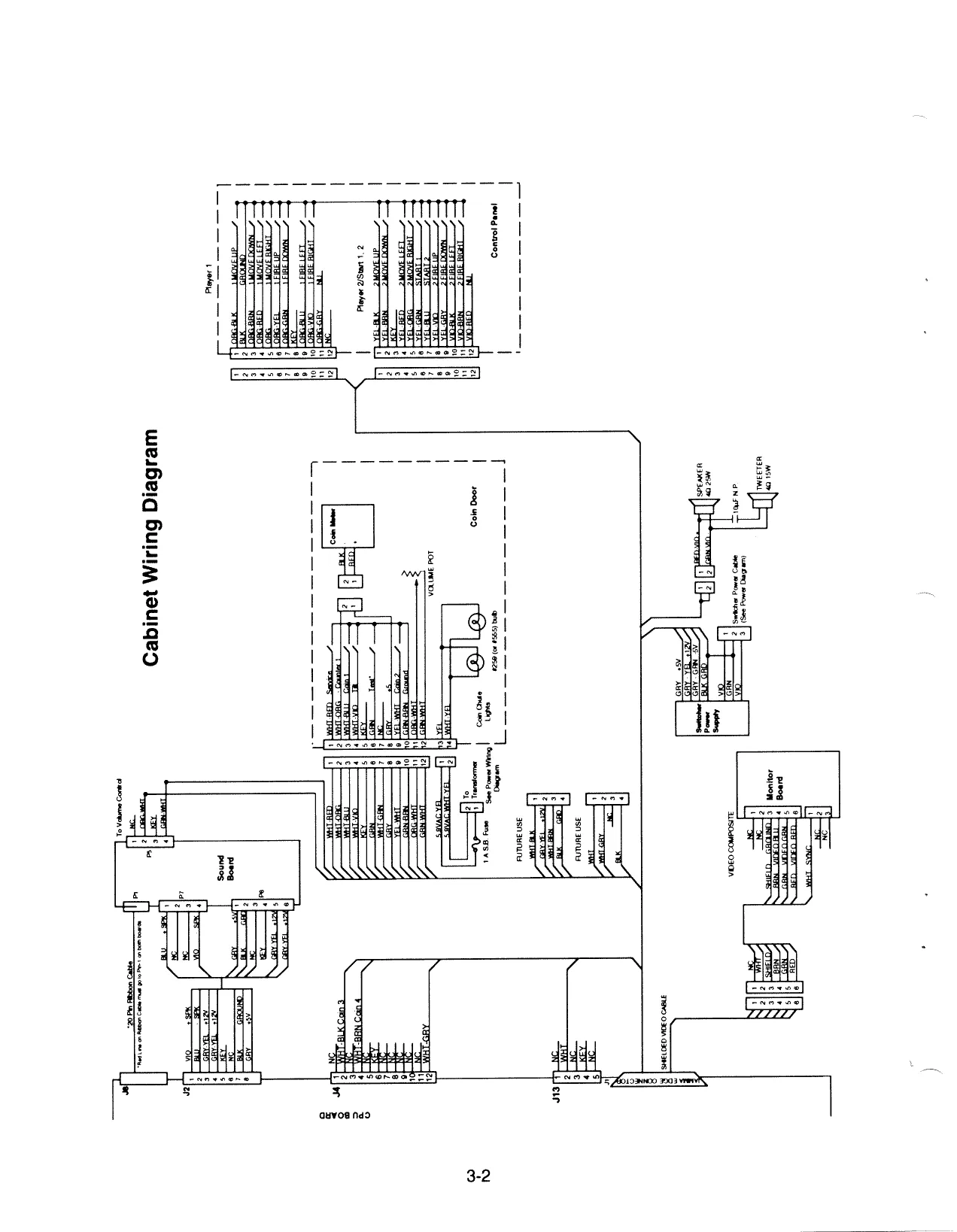
This page is a drawing, shown as the original scan.
Power Wiring Diagram |. BLK tif To ON/OFF #]2||2|)GBN___LiGHT FIXTURE
| SWITCH | 3) | (9) WHT | gone |
4|[4Ca SA.8LO BLK-YEL J. = 50Hz
| Nf | au fy | 1] | [7 Lwoa | 4 | 1) | i ve | To |
| : | 2all2 | . | ={2||2 [SBN Power suprty | ||||
| | | 31/3 [vos | “|3 || 3 [wo | |||||
| | | = | 41/4) vio. vet a | Lj | ||||
| Jo Py | 4 | vELWHT | 1 | {1 es | To | ||
| 4 | YE | wh | sovat | *¥}2||2 -SBN=YEL- | monitor | ||
| WHT-RED. | SEE | alle | TO | 3] | | 3 WHT |
AC TRANSFORMER ave COIN DOOR PLUG CHART 1A, 8B.
Transformer Chart
FROM POWER
| SWITCHES, | 15 PIN CONNECTOR | 4 PIN CONNECTOR | |
| YEL | _ | 3 | WHT. |
| Zl 6 | So | war | my |
~ $< | 120V ISOLATED FOR
| — | ° | 2A | MONITOR AND POWER |
>
| je |12| | 2 | ayer | 4 |. | SUPPLY | |
| NOTE: | 15 | RED | 13; | ~YFl 2. |
| |SHOWN AS | SEE | >| 5] | 5 | etu- war | Q |
JUMPERED | VOLTAGE m|
| FOR | SereeTiON | 8 | AIU-RRN | 103 | WHT |
tisvo.t | tape = [11] fee 5.9 FOR COW DOOR = UGH
| OPERATION | XFMR 5610 - 12559 - 00 | is |
| 7 | BLK | 2PIN |
nal FA CONNECTOR fm ae} = =| 13 BL
TO POWER WHT - RED le | 2 Fi ‘ROM LINE “BL Yel SWITCHES >|! FILTER
Voltage Selection Table
VOLTAGE __JUMPER PIN: 103.5 5-6,7-8,10-9
| ‘i | 115 | 5-6,7-11,10-12 |
132, 5-67-14, 10-15 207, 5-9,10-8 218.5 5-9, 10-11
| . | 230 | 5-12, 10-11 |
247 §- 12,10 -14
JAMMA CHART
| Function | Wire Color | Pin | Pin | Wire Color | Function |
| Ground | Black | 4 | A | Black | Ground, |
| Ground | Green-Brown | 2 | |B | Black | Ground | |
| +5 Volts DC | Gray | 3c | Gray | +5 Volts DC__| | |
| +5 Volts DC | ray | 4 | D | ray | +5 Volts DC |
| -5 Volts DC | Gray-Green, | 5 | E | Gray-Green | -5 Volts DC |
| +12 Volts DC_| Gray-Yellow | 6 | F | Gray-Yellow | +12 Volts DC | ||
| ey | 7H | ey | |||
| Counter 1 | ‘White-Orange_| | 8 | J | White-Green | [Counter 2 | ||
| NC. | E] | K | NC. | ||
| Speaker (+) | Red-Violet | 10_|_L| | Green-Violet__| | Speaker () | ||
| NC | 11 | [mM _| NC | |||
| Video Red | Red | 412 | N | Green | Video Green | |
| Video Blue | Brown. | 13_[ | P| | White | Video Sync | |
| Video Ground | Shield | 14 | _[_R_| | White-Red | Service Credit | |
| [Test | Green | 15_|_S__| | White-Violet | Slam Tit | |
| 1 Coin, | White-Blue_ | 16 | T | Yellow-White | [2 Coin | ||
| 1 Start | Yellow-Green_ | 17 [ U | Yellow-Blue | 2 Start | |
| 1 Up Move | Orange-Black | 18 | V | Yellow-Black | 2 Up Move | |
| 1 Down Move | Orange-Brown_| | 19 | W_| | Yellow-Brown | "2 Down Move | |||
| Left Move | Orange-Red | 20 | |x | Yellow-Red | 2 Left Move |
1 Right Move | Orange” 21_|_Y _| Yellow-Orange | 2 Right Move
| 1 Up Fire | Orange-Yellow | 22 [| Z | Yellow-Violet | 2 Up Fire | ||
| Down Fire] | Orange-Green_| | 23 | a__| | Yellow-Gray | —|"2 Down Fire | |
| 1 Left Fire | Orange-Blue | 24 | b | Violet-Black | 2 Left Fire | |
| 1 Ri | i | | Orange-Violet | 25 | | — | |
| NU. | Orange-Gray | 26 | d | Violet-Red | NU. | |
| NC | 27 | |e | NC | |||
| Ground, | Black | 28 | f | Black | Ground |
INTERBOARD WIRING DIAGRAM i
‘1 Fa
| JAMMA Edge Connector see | ee | a (8 | E |
| basauabehceil | Ses use | sllset | |
| Wolueed | u | 12345678 | 423456789 1011 12] |
a7 2 ve
Power To Sound
rape ne 3 wey —f}e|_ NC olf 2 weet el? § wet] 8 Y-UNIT CPU BOARD
Fem Pt On Sound Board
| SSA | OB | a | 6 |
| Not Ueed | —_—a | rated | Neves |
BR) | (lal ae BECEEE es43et
| PY | 6 | nc |
3 yo FIBBON CABLE ee =
| 5 x | Fei | TOCPU | coe | ws |S | caswit 3 |
| 3 aol | |” | 2 | Fferamr §* |
SOUND BOARD
3-4
HOA CK 1097. £UK boc CPU Sheet 1 of 16
CPU Sheet 2 of 16
LOCAL ADDR BUS "xt VIDEO OATA AU
3-7 vay YVRAMCTL aT
uae eo. s
YADDROES rae Sas V2T =n 199. CPU Sheet 3 of 16
3-8 as 3ST PPePeeeel 9b 40 y 18S
Ndd
3-9 __Locat_ aon aus CPU Sheet 5 of 16
( =] Se waa Ww5OT
wet wey a j Pray o1-eeus, or-vaus: 9140.9 100US
Ndd
3-10
91 40 2380US
3-11
9140 8 380US Ndd
3-12
91 $0 6 04S Ndd
AMON JOWH
3-13
3-14 CPU Sheet 10 of 16
9b JO LL 80S
Ndd Sno vied Wins
og xe 30H arr) wwe Lay 19 Jour TEs oie woo OTaTA
3-15
3-16 us YeRAMCTE CPU Sheet 12 of 16
cP600 Loot
Cis!
qATIIIT Ty
pio cL Le wot [b- oar a am _ — RESO,
us2 ‘YRAMSEO cP 600
LOCAL DATA aus 08). PALLEN
QL JO EL 390US
Ndd
3-17
oor ‘sie woo 109 i i cpu (a3sn Lon)
Sie vive wows 9b 40 HL e0US
Ndd
3-18
3-19 LOCAL ADDR AUS CPU Sheet 15 of 16
3-20 CPU Sheet 16 of 16
wgive cue zswczterurs>Fnrneavves iT T tO IN
mass
ssoreweex ‘
MIGHOLE MIGHOLE MTGHOLE [Cures — [Qytce Tot oS ae
v7
ui
a
OD
oH
ts be doe a Be Tsay
Tas
u2t ee "ost
Kane ] v2t ry E | aad onkIN aw a we] Kav rep | SBE te es = Sew re FE ten Spot «ve he } zit ie eam ioe Seah ees He ete = SSRoah by ares omy bal + a
Sound Board sheet 1 of 4 (Speech Synthesis)
ee ee 3-21
1C
B
A
Sound Board sheet 2 of 4 (Music Synthesis)
| 7 | 3-22
yyy) |
st |
Sound Board sheet 3 of 4 (Amplifier)
3-23
Sound Board sheet 4 of 4 (Interface)
3-24
rane
Ke
vagrant ohne ae
wissen
Jumper Charts
Sound Board
W2, W3, W5, W7, W8
CPU Board
W2, W8, W11, W12, W14, W21, W22, W24, W27, W29, W31, W32, W34, W36, W39, W41, W42, W45, W47, W48, W50, W52, W55, W57, W58, W60, W62, W66, W68, W69, W71, W73, W75, W77, W80
WARNINGS & NOTICES
- For safety and reliability, substitute parts and modifications are not recommended.
- Substitute parts or modifications may void FCG type acceptance.
- This game is protected by Federal Copyright, trademark and patent laws. Unauthorized modifications may be illegal under Federal law. This also applies to MIDWAY logos, designs, publications and assemblies. Moreover, facsimiles of MIDWAY equipment (or any feature thereof) may be illegal under federal law, regardless of whether or not such facsimiles are manufactured with MIDWAY components.
Notice When MIDWAY ships a game, it is in compliance with FCC regulations. Your sticker is proof. If the sticker is missing or damaged, legal repercussions to the owner or distributor of the game may result. If your game does not contain an FCC sticker, call MIDWAY immediately.
Notice No part of this publication may be reproduced by any mechanical , photographic, or electronic process, or in the form of a phonographic recording, nor may be transmitted, or otherwise copied for public or private use, without permission from the publisher.
Entire contents of this manual copyright ©1991 MIDWAY Manufacturing Company. All rights reserved
For Service: Call your Authorized MIDWAY Distributor.
MIDWAY Manufacturing Company
3401 N. CALIFORNIA AVE. CHICAGO, ILLINOIS 60618