Smash TV 25in (16-3044-U1-101) Apr 1990
Smash T.V. (rev 8.00) (Williams, 1990) · Manual · 58 pages · 53 sections · original scan
NCATE eu W : Sr OPERATIONS MANUAL. including: A ;
Game Operation & Adjustment
Game Testing & Problem Diagnosis
Parts Information __ L
Reference Diagrams & Schematics
WILLIAMS ELECTRONICS GAMES. INC.
3401 N. California Avenue
Chicago, IL 60618
‘The year is 1999
Television has adapted to the more violent nature of man.
The most popular form of television remains the game show.
One show in particular has dominated the ratings. That show is SMASH TV. The most violent game show of all time
SMASH TV. The most violent game show of all time.
Two lucky contestants compete for cash and prizes. Each contestant is armed with an assortment of powerful weapons and sent into a closed
arena.
‘The action takes place in front of a studio audience and is. broadcast live
via satellite around the world.
Be prepared.
The future is now.
You are the next lucky contestant!
- Move with LEFT joystick to avoid enemies and gather prizes (cash and game show gifts).
- Fire weapons with RIGHT joystick and collect power-up icons for increased firepower.
- Advance to next game arena when enemies are gone.
TABLE OF CONTENTS
Section 1 Operation and Troubleshooting
SOBEL. ecsseccseresetesseesssees ave igevnbent aac vase achegneenavansacesrensranmeasion eurvvieishuunseate cégcaivotanenarteas 1-2 Set-up Procedure Installation & Inspection. 3 Location Requirements. Cabinet Assembly Diagram. Servicing........... iiteavenasennan eave Game Features Starting-up. Player Control.. Control Panel Diagra Game Operation Control Switches Control Switch Location Diagram, Game Adjustment & Diagnostics Starting-up.. Main Test Menu.
DIP Switch Test & Chart. CPU & Sound Tests. Monitor Patterns & Bum-in Coin Bookkeepin: Game Audis... Game Adjustments. Standard Pricing Chai Utilities, Troubleshooting.
Section 2 Parts Information
Cabinet, Speaker, & Lamp Parts. PC Boards, Transformer, Control Panel, & ‘Monitor. Cables, & Manuals. Audio Board.
Section 3 Diagrams and Schematics
Audio Board Schematic. CPU Schematl......... JAMMA Edge Connector Chart. Cabinet/Contro! Panel Wirlng Diagra Power Wiring Diagram. Interboard Wiring Diagram. Control Panel Wire Colors...
SMASH TV
Operation and Troubleshooting
Safety Notices
The following safety hints apply to all game operators and service personnel. Specific warnings and cautions will be found throughout this manual where they apply. We recommend that youread this page, and also all of Section 1, before preparing your game for play.
WARNINGS AC POWER CONNECTION. Before connecting the game to the AC power source, verify that the "line voltage selection chart’ jumper wires are Installed correctly for the line voltage In your area. For defalls, refer to Section 3.
PROPERLY GROUND THE GAME. To avoid electrical shocks, do not plug In the game until it has been Inspected and properly grounded. WILLIAMS games should only be plugged Into a grounded 3-wire outlet. Shocks wit also result, If the control panel Is not properly grounded! Afterservicing any parts on the panel, assure that the ground wires are secure. Only then should you lock up the game.
DISCONNECT POWER DURING REPAIRS. To avold electrical shock, disconnect the game from the AC power source before removing or repairing any part of the game. When removing or repairing the monitor, extra precautionsmust be taken to avoidelectricalshock because high voltagesmay exist within the monitor circuitry and cathode ray tube (crt) even after power has been disconnected. Do not touch intemal parts of the display with yourhandsor metal objects! Always discharge the crt: attach one end of a large, wellinsulated, 20-kV Jumper to ground. Momentarlly touch the free end ofthe groundedjumperto the anode byslidingit underthe anode cap. Walttwo minutes and discharge the anode again.
USE THE PROPER FUSE. To avoid electrical shock, use the replacement fuse which Is specified In the parts list for this game. The replacement fuse must match the original fuse in fuse type, voltage rating, and current rating.
HANDLE FLUORESCENT TUBE AND CRT WITH CARE. If you drop a fluorescent tube or CRT and It breaks, it will implode! Shattered glass can fly elght feet or more from the implosion.
PROPERLY ATTACH ALL CONNECTORS. Make sure that the connectors on each printed circult board (pcb) are properly connected. If they do not slip on easily, do not force them. Areversed connectormay damage your game and vold the warranty. All connectors are keyed to fit specific pins oneachboard.
Setup Procedure
Installation and Inspection
1, Remove the game from Its shipping carton, and inspect the exterlor of the cabinet for any signs of damage. Remove the shipping cleats from the bottom of the cabinet.
- Remove keys from the taped coin retum slot (or attached to Joystick). Unlock and open the coin and cash box doors. (Leg levellers and spare parts are stored In the cash box.)
- Locate the four threaded holes on the bottom of the cabinet (one In each corner),and install one leg leveller (with Its hex nut) in each hole.
4, Stand the cabinet upright and make certain that it isin a stable position. Level the cabinet.
- Unscrew (or unlock) and remove the rear doors/panels of the cabinet. Inspect the Interlor for any signs of damage. Check all major assemblies to assure that they are mounted securely.
- Refer to the game's cabinet wiring diagram (Section 3), and check tosee that all cable connectors are correctly secured and firmly seated. DO NOT FORCE CONNECTORS. Watch for damaged connectors and avoid making reversed connections.
7, Line Voltage Selection. Your game is designed to work properly on the line voltage where you are located. Determine the value of your line voltage with a meter. Then, check the power Input wires to the main power supply transformer on your game to be sure they are connected to taps which correspond to your local line voltage value. Ifnecessary, reconnect the power input wires to the transformer In accordance with the Tranformer Chart in Secton 3,
If the line voltage in your area falls outside the upper or lower limits of the range of voltage Inputs covered by the main powe supply transformer, DO NOT PLUG YOUR GAME IN until you have contacted your distributor or the WILLIAMS Service Department and obtained asolution to the problem. Otherwise, you could damage your game.
- Lay the line cord (connected to the Power Chassis) In the slot along the bottom edge of the lower rear cabinet door/panel. Install the rear cabinet doors/panels and screw (lock) them securely. Close and lock the front coin and cash box doors.
- Connect the line cord to a grounded (3-terminal) AC wall outlet.
- Switch ON the game, using the ON/OFF switch located on the upper left rear of the cabinet, to verify proper operation.
1-3 GAME LOCATION REQUIREMENTS
Power Domestic 115V @ 60 Hz Foreign 230V @ 50 Hz
Temp. 32° F to 100° F (0° C to 38° C)
Humidity Not to exceed 95% relative.
25" Cabinet (Front View)
Marquee Glass
Viewing Glass
Monitor Screen
Credit Buttons
Joystick
Servicing
@ Servicing the Control Panel Switch OFF power to the game. The control panel is held In place by fourlatches (located on the left and right sides of the cabinet) which provide constant pressure on the strikes. The latches can be reached through the coin door opening. To release the latches, lift the latch handle and unhookthe wire fasteners. Carefully use the Joysticks to lift the control panel. Rest the panel on its support bracket, while working on It. To reinstall the contro! panel, check forpropercable connections, including the ground strap, and use the Joysticks to lower tt into position, avoiding pinched wires. Reclamp the latches.
Removal of Viewing Glass
Switch off power to the game, and open the control panel. Unscrew the four nuts at the bottom of the glass and remove the protective black plastic strip. Carefully lift the glass from its bottom groove and lift it clear of the cabinet.
Removal of Monitor Bezel Switch off power to the game, and remove the viewing glass. Remove the bezel securing screws to free the monitor bezel.
Monitor Replacement
We recommend that you read the WARNINGS section thoroughly before beginning this procedure. Switch off powertothe game. Open the upper rear door/ panel. Remove the viewing glass and the monitor bezel. Completely disconnect the monitor from alll of its cabling, Including its chassis ground strap. Remove the four bolts securing the monitor's mounting flanges to its mounting panel. Pull the monitor carefully from the cabinetfront. The monitor DOES NOT contain an isolation transformer in its chassis (it is mounted instead in the Power Chassis Assembly located on the floor of the cabinet). Whenservicing the monitor on a test bench, YOU MUST ISO- LATETHE MONITORFROM THE LINE VOLTAGE WITH AN ISOLATION TRANSFORMER.
While removing the four bolts, firmly support the monitor from the front of the crt so that it will not slip.
The fluorescent tube is now accessible for replacement. Grasp the tube, give it a quarter turn, and remove it from itssocket. Carefully place anewtube intothe socket, and turn to reinstall.
@ Removal of the Fluorescent Light
Assembly
Switch off power to the game. Remove the marquee glass. Disconnect the fluorescent light assembly from its power cable. Remove the screws fastening the assembly to the cabinet and lift out the assembly.
@ Removal of the Speakers Switch off power to the game. Remove the upper rear cabinet door/panel, taking care to not damage the speaker enclosure seals. Disconnect the speakers from their cabling. Remove the nuts on the speaker mounting bolts. Remove the speakers. Because the speakers are mounted inan acoustical enclosure, carefully reinstall the seals upon completing any task in the speaker enclosure.
Volume Control, Test/Diagnostics Switch, and Service Credit Switch Open the coin door to locate the game's volume control and Diagnostic switches on the smail panel atop the cash box cover. The Volume Control is the white knob on left end of the panel. Tuming the knob clockwise increases the volume. The upper right switch on the bracket is the Test/Diagnostics Switch that enables activating the game's test mode. The lower right switch is the Service Credit Switch, which allows adding credits to a game for service testing without affecting the game's bookkeeping total.
1-6
Game Features
Starting Up
Switch onpowerto the game. A ‘rug’ pattern appearson the SMASH TV is a one or two crt screen. When the ‘rug’ pattem ends, the screen shows player game. CHECKING SCRATCH RAMS, and then CHECKING ROMS. The next screen shows SMASH TV REVISION LEVEL, CMOS TEST OK and the COIN SETTING. The game then moves fo the attract mode, After the proper coinage has been inserted, the game exits the attract mode and enters the play mode.
Player Controls
SMASH TV will operate in the Test Each Credit button allows (1 or 2) players Mode, when the Test Switch (on to begin play or continue play. ne heptane Neca he closed.
Left Joysticks enable players to move When an error Is detected during through arenas Start-up Tests, game start-up
ig . does not progress, and an error
message appears on the screen.
§4 Right Joysticks enable players to fire on enemies in arenas.
SMASH TV PLAYER CONTROL BOARD
One Player -~ Two Player
Credit Button (@) ©) Credit Button
Move Fire Move Fire
Game Operation
SMASH TV is a one or two player video game with a color monitor. From the player's perspective, the game has two modes of operation: Ready-to-Play and Play. Forthe owner/ operator, the game has an additional mode of operation called Game Diagnostics and Adjustments.
Control Switches
—@ The COIN DOOR SLAM TILT SWITCH detects any forceful vibrations against the Coin Door. This eliminates pounding for free games.
—™ The VOLUME CONTROL allows increasing or decreasing the volume level of the game music and speech. For greater profits, set your game's volume level at its maximum.
—@_ The TEST/DIAGNOSTICS SWITCH allows you to enter into the game's Diagnostic mode. Move the Test Switch to the left, then back to the right to enter the Diagnostics Mode. To exit this mode, select EXIT TO GAME OVER from the Diagnostics main menu.
—Z_ The SERVICE CREDIT SWITCH Is a special feature switch that allots credit without affecting the game's bookkeep- Ing total.
E— The POWER INTERLOCK SWITCH Is a safety switch that ensures power to the game is turned off during servicing. This switch is located inside the lower rear door/panel.
Slam Tilt Switch
Volume Control
Test/Diagnostics Switch
Control Switch Locations
1-8
Game Audits, Adjustments & Diagnostics
Operation
AIlISMASH TV Game Audits, Adjustments, and Diagnostics are options of the Main Test Menu. Each option, in tum, has Its own menu. listing several choices that you may act upon as desired.
Move the Test Switch (on the cashbox lid panel) left, then back to the right to activate the SMASH TV Adjustments and Diagnostics. Main Test Menu (shown below) then appears. Game adjustments, bookkeeping, and diagnostics are all accessible from this menu,
Move the left joystick up or down to cycle through the menu options. Notice that the options are highlighted insequence. Selecting a desired option requires It to be highlighted. To activate the selected option.move the right joystick.
The Main Test Menu lists six options.
__EXITTO GAME OVER
Main Test Menu
DIAGNOSTIC TESTS To enter the Diagnostic Tests from the Main Test Menu, move the left joystick to select (highlight) the Diagnostic Test option, and move the right joystick to activate the option. The Diagnostic Tests Menu lists seven options.
RETURN TO MAIN MENU
Diagnostic Test Menu
Switch Test The Switch Test allows the operator to test the switches onthe control panel and the coin door.
Select the Switch Test by using the leftjoystick to highlight the Switch Test option: then, move the right joystick to activate it. The top of the screen shows a layout of the control panel and the bottom of the screen lists the coin doorswitches. Pressing a switch causes the corresponding switch location on the screen to light. Release the switch and the screen returns to normal.
Select the RETURN TO MAIN MENU option to return to the DIagnostic Test Menu.
1-10
DIP SWITCH TEST
Please Note: Dip Switch information will be provided when available.
1-11
As soon as a faulty chip is detected, the CPU Test stops. The remaining chips are not tested. CPU Board Test The CPU Board Test (much like the Start-up Test) allows the operator to check the RAMs and ROMs.
Move any joystick to select the CPU Board Test; then, press any control panel button to activate the automatic test of the CPU Board's RAMs and ROMs. When this fest is activated, a "rug" pattern appears on the screen. The screen then changes to show the layout of the RAMs, and ROMs on the CPU. Any chip that is shown as black with a white outline is part of the CPU and should turn either red or green during the CPU Test. Any chip that is shown as gray with a white outline is not installed in the game. During the test, chips are good, if they turn green; they are faulty, if they turn red.
Press any control panel button to retum tothe Diagnostic Test Menu.
Sound Board Test The Sound Test allows listening to some of the sounds that SMASH TV is capable of producing. This test also emits atone for each fault that is detected.
Move any joystick to select the Sound Board Test; then, press any control panel button to activate the test.
1-12
Monitor Patterns The Monitor Patterns Test provides a menu for testing the monitor.
Move the left joystick to select a test; move the right joystick to activate the test.
(Select wih EFT STICK») | ACTIVATE WiTd RIGHT STICK ) (as | GREEN SCREEN _ BLUE SCREEN COLORBARS CROSSHATCH PATTERNS
BACK TO DIAGNOSTICS MENU RETURN TO MAIN MENU
y
Monitor Pattem Menu
The RED, GREEN, and BLUE SCREEN tests fill the screen with either red, green or blue. Tne COLOR BARS test fills the screen with several gradiated colors to help with red, green and, blue level adjustments. Each color should appear sharp and clear. Tne CROSSHATCH PATTERNS test fills the screen with a grid and a series of dots. The grid and the dots should be clear. The dots should appear round.
if any of the Monitor Pattern Tests shows a need for adjust-. SMASH TV provides front-mounted ment, use the proper white knobs on the Monitor Board. Monitor Board controls. These controls are accessible within the Move right joystick to retum to the Monitor Patterns Menu. Control panel opening beneath From this menu, select RETURN TO MAIN MENU with left the monitor. Joystick and activate with right joystick.
Burn-in Test The Burn-in Test continually repeats the CPU Board Test. Move any joystick to select the Bum-in Test; then, press any button to activate the test. When the Burin Test detects an error, the test stops and displays an error message on the screen. The third page of the Audit Table specifies the number of Burn-in cycles successfully completed. Use this test to find intermittent CPU problems.
To exit this test, switch off the game; then, switch it on again.
1-13
COIN BOOKKEEPING To enter the Coin Bookkeeping from the Main Test Menu, move the left joystickto select the Coin Bookkeeping option; then, move the right joystick to activate it.
The Coin Bookkeeping Table records the coinbox totals and game play counters. The left side of the table names the bookkeeping item; the right side shows the number of coins, credits, or plays for each item.
Coin Bookkeeping Table
To exit Coin Bookkeeping, move the left joystick to select RETURN TO MAIN MENU; then, move right joystick to activate it.
GAME AUDITS To enter Game Audits from the Main Test Menu, move the left joystick to select the Game Audits option; then, move the right joystick to activate tt. To advance to the next (or return to the previous) page of the Game Audit Table, move any joystick to select either "Next Audit Page", or “Previous Audit Page": then, press any control panel button to change the page.
The Game Audits Table records the game play statistics. The left side of the table names the Audit item: the right side shows the amount of play. 1-14
“NEXTAUDITPAGE | RETURN TO MAIN MENU _
PAGE 1 OF AUDIT TABLE
_ GAMES STARTED (ALWAYS FROM WAVE 1) __ REACHED WAVE 2
ey) PAGE 2 OF AUDIT TABLE
To exit the Game Audit Table , move the left joystick to select RETURN TO MAIN MENU; then, move right joystick to activate it.
GAME ADJUSTMENTS Move the left joystick to select the Game Adjustment option on the Main Test Menu; then,move the right joystick to activate it.
The Game Adjustments option allows the owner/operator to change the Game Pricing and Game Difficutty.
The Game Adjustment Menu offers several choices. Each choice hasitsownmenu. Move the left joystick toselect your choice to be changed from the Game Adjustments Menu; then, move right joystick to activate that choice. Onthe next menuscreen,move theleft joystick to select the item you wish tomodify; then, move the right to activate that item. Ifthe activated item only provides a setting choice, move the left Joystick to change the current setting to the desired value; then, move the right joystick to lock In the desired value. Moving the Joystick up increases the setting value shown on the screen. Moving the Joystick down causes the value shown on the screen to decrease.
Game Adjustment Menu
1-16
Standard Pricing
Standard Pricing allows the operator to choose any of the “Standard” selections for the Standard Pricing Table. Standard Pricing cannot be Installed when either Custom or DIP Switch Pricing Is in effect.
The SMASH TV Standard Pricing Table is on page 1-19.
Move the right Joystick to return to the Game Adjustments Menu.
Custom Pricing
Custom Pricing allows the operator to install pricing other than that of the Standard Pricing Table. Custom Pricing also allows the operator to selectthe maximum amount of credits per game, the amount of credits required to start a game, and the amount or credits required to continue a game. Custom Pricing cannot be installed when DIP Switch Pricing is in effect.
Move the right joystick to return to the Game Adjustments Menu.
Game Difficulty
Game Difficulty allows the operator to select the difficulty level of the game. The range of this setting is Easiest (1) to Hardest (10).
Move the right joystick to return to the Game Adjustments Menu.
Lives per Play Lives perPlay allows the operatorto select the number of lives aplayer receives each time a game is started or continued.
Move the right joystick to return to the Game Adjustments Menu.
Attract Mode Sound Attract Mode Sounds allows the operator to determine if the game has sound during ihe Attract Mode.
Move the right joystick to retum to the Game Adjustments Menu.
Auto High Score Reset
Auto High Score Reset allows the operator to determine how many plays must occur before the all time high scores are automatically reset to factory settings.
Move the right Joystick to retum to the Game Adjustments Menu.
Violence Level Allows the operator to determine the Volence Level of the game.
Move the right Joystick to retum to the Game Adjustments Menu.
To retum to the Main Test Menu, move the left joystick to select RETURN TO MAIN MENU; then, move the right joystick to activate,
1-18
SMASH TV STANDARD PRICING TABLE
SETTING
FRANCE 1 2/5 F 5/10 F
UTILITIES On the MainTest Menu, move the left joystick to select the Utilities option; then, move the right joystick to activate it,
The Utilities option allows the owner/operator to clear the game's bookkeeping memory and to install a custom message. (SELECT WiTH LEFT STICK
ACTIVATE WITH RIGHT STICK
(Ga. CREDITS
J
Move the left joystick to select an item from the Utilities Menu; then, move the tight joystick to activate that item. After an item has been activated, you are given the option of resetting the item or not. For example;
CLEAR CREDITS ARE YOU SURE ?
[NO |
Move the left joystick to choose YES or NO; then, move the tight joystick to lock in your choice and to retum to the Utilities Menu.
To exit Utilities, move the left joystick to select RETURN TO MAIN MENU; then.move the right joystick to activate it.
1-20
Troubleshooting
Problem Possible Solution
NO PICTURE Check for faulty video board or OR DISTORTED monitor. Check for disconnected PICTURE. video signal cable.
TURN GAME ON & Check line fuse. Check for +5V de NOTHING HAPPENS at pins C, D, 3, and 4 of the JAMMA Connector.
NO SOUND Check the speaker and speaker connection to pins L and 10 on JAMMA Connector. Check volume control setting. Check for +12V de at pins F and 6 on the JAMMA Connector. Check interboard wiring from CPU Board to Sound Board.
NO GENERAL Check the 1A., S-B fuse on the ILLUMINATION cabinet wall above the coin box.
MOVE JOYSTICK, Check for open wires between BUT PLAYER DOES Joystick and CPU Board. Check for NOT MOVE OR FIRE — contamination on joystick switch contacts and CPU Board pins. Check for proper ground.
PRESS START Check for open wires between BUTTON AND button and CPU Board. Check for NOTHING contamination on CPU Board pins HAPPENS or button switch blade contacts. Check for proper ground.
NO CREDIT GIVEN Check DIP switch coin setting. WHEN COINS ARE Check for contamination on coin INSERTED switch contacts. Check for an open wire between Coin Switch 1 and pin 16 on JAMMA Connector or Coin Switch 2 and pin T of JAMMA Connector.
TOO MANY CREDITS Check Game Pricing setting. Check FOR NUMBER OF for a short between pins T & 16 on COINS INSERTED JAMMA Connector.
GAME STAYS INTHE — Check that the Test Switch in the coin
TEST MODE. door and the Test Switch (Position 8) on DIP Switch 2 are set to Off.
1-21 SEE NOTE
SMASH TV
SECTION
two
Parts Information
2-1
Cabinet Hardware
Cabinet Assembly A-11-948-3044-U1 Caster Wheel Assembly B-13086 Control Panel Assembly D-13570 Leg Leveler Plate 01-9155 Leg Adjuster 08-7377 Wood Cabinet 11-948
Back Door Assembly B-13574 Lock Retainer 01-7264 Upper Door Cam Lock 01-8989 Rear Wood Door 11-934 Door Cam Lock 20-6542-TB
Line Voltage Cable Assembly C-12773-4 Mtg Pit Toggle Assembly A-9958 interlock Spring Brkt. Assy B-12907 Line Voltage Cable H-13555 Protective Cap 17-1038-2 Toggle Switch, 227V,15A. 5640-10932-00 Interlock Cheat Switch 5643-09556-00
Over/Under Coin Door D-13250 Test Switch A-13115 Coin Door Cable H-13215 Coin Door USA 09-20000-V-1 12 pin "Z* Header 579 1-12235-12
Speaker Grille 31-1554-3044-U Test Switch Bracket 01-9383 Marquee Retainer 03-8252-2 Lock Lamp 03-8327 Glass Edge Channel 03-8358 Wood Speaker Door 11-935 Wood Control Panel 11-950 Toggle Latch 20-9347 SMASH TV Marquee 31-1551-3044-U1 Glass CRT Cover 31-1552-3044-U1
Speakers
Piezo Speaker Assembly B-13587-1 4" Piezo Speaker, SOW 5555-12068-00 6" Round Speaker, 8ohm, 20W 5655-12015-00
Fluorescent Lamp Parts
Fluorescent Housing & Bracket C-12679 Housing Mounting Brkt 01-9146 Light Fixture 20-9590. 18" Fluorescent Bulb, 15 W =. 24-8809 2-2
PC Boards
Y-Unit CPU Assembly C-13234-3044 Power Supply Assembly C-13253-1 Audio Sound Board Assembly D-11581-3044
Transformer Assembly
Power Pack Assembly D-13252 Line Cord Assembly A-13340 Power Transformer A-13771 Power Pack Chassi Assy C-13251 Power Pack Jumper Cable H-13265 Line Fitter Jumper Cable H-13344 Transformer Jumper Cable H-13378 Varistor, 130V, 10J 5017-09044-00 Line Fitter, 5Amp 5102-08895-00 Fuse, SB3A, 125V 5731-08633-00 Fuse Holder, Panel 5733-10358-00
Control Panel
Control Panel Assembly D-13570 Control Panel Plate Assy C-13560 White Button Assembly C-9214-5 Control Panel Bracket 01-9651 Wood Control Panel 11-950 5/8 Palinut 20-9222 8 Way Red Joystick 20-9319-1 Screened Overlay 31-1547-3044
Monitor
Monttor 25" 5675-12621-00
Cables
Video Sound/Power Cable H-10217-4 Sound Board Jumper Cable H-12758 Speaker Cable H-13213 Coin Door Cable H-13215 Power Pack Jumper Cable H-13265 Line Fitter Jumper Cable H-13344 Transformer Jumper Cable H-13378 Main Hamess Cable H-13583 Line Voltage Cable H-13555 Control Panel Cable H-13584 Sound/ Power Speaker Cable H-13257 20 pin Ribbon Cable 5795-10937-18
Manuals
Monitor Manual 16-3000-103 Instruction Manual 16-3044-U1-101
2-4
ure
| pepezosees 22.00.9001
PartNumber Ckt Dealgnator
6768-12130-00 6371-11087-00 U1
- 6700-09008-00 6370-11086-00 U3
- 5700-10176-00 6371-09162-00 U11 ui2 Us ure urs 6430-10322-00 6340-10139-00
u2 ut4 U1s vet U9, U10, U17, U16 IC, Op Audio Board Assembly p/n D-11581-3044
Description
Bare P. C, Board 1G, D/A Conv, YM3012 Socket, IC, 18-pin (U1) IC, Sound Processor, YM2151 Socket, IC, 24-pin (U3) IC, uProcessor, MC88BO9E Socket, 1C, 40-pin (U8) IC, Audio ROM 1 IC, Audio ROM 2 IC, Audio ROM 3 Socket, !C, 28-pin (U4, U19) IC, D/A Convtr, MC1408 1C, PIA, MC8sB21 IC, RAM/S 6516-2 2Kxe IC, Dual D Flipflop, 741874 IC, 7418175 IC, Triple NAND, 741510 ‘Amp, MG1458. IC, Hex Inv, 74804 1c, 2-4 Deo, 7418139 1C, Dual Mux, 7418138 Uz2, U23 {C, Audio Amp, TDA2002
- 5705-09199-00 Heatsink, #6030B
- 4006-01003-06 Mach. Screw, 6.32 x 3/8 ¢) 4408-01117-00 Nut, 6-32 Hex. @) 4703-00007-00 Lockwasher, #6 Ext.
| 5160-10269-00 | Q1 | Transistor, 2N3904, NPN. |
| 5080-10396-00 | SP1 | SIP 4.7K & 470ptd, 8REC. |
| 5010-09181-00 | A44, Ras | Resistor, 1.00, 1/2w, 6% |
| 6010-09161-00 | R35, R45 | Resistor, 2.28, 1/4w, 5% |
| 6010-09361-00 | A43,A46,A47 | Resistor, 220, 1/2w, 6% |
| 5010-09958-00 | A41, R42 | Resistor, 1K, 1/4w, 5% |
| 5010-08908-00 | 2, R3, | Resistor, 2.2K, 1/4w, 6% |
| 5010-06963-00 | A7-R9 | Resistor, 3.9K, 1/4w, 5% |
| 5010-08991-00 | At, R4, 5, 11, | Resistor, 4.7K, 1/4w, 5% |
R26 - R28, R36, R37, R49, R50
“17 capacitors (shown on diagram with “B" symbol) provide +5VDC fitering for ICs, All capacttors are ceramic, 50v, axial, unless otherwise noted. All resistors are 6%, 1/4w, Carbon Film, unless otherwise noted. Notes: PertNumber Ckt Designator
6010-10985-00 R14, R16 6010-09034-00 R22-Fi24, R17, R34 5019-09324-00 Re, R19, R20, A21 6010-09162-00 R39 6010-09331-00 R16 6010-08772-00 R18. 6010-08824-00 R32 6010-08846-00 R31 6010-08991-00 R12 5010-09219.00 R38 6010-10258-00 R40 6010-09179-00 R10 6010-09333-00 R29 6010-09342-00 R30 5010-09534.00 Wo 5040-08343-00 C1, C3, C4, C8 5040-10974-00 012, C19, C24. 5040-09776-00 C26, C30 6040-12006-00 C29, C32 6041-09243-00 C25, C28 5043-08980-00 C5, B (17)* 5043-08996-00 C31, C33 5043-09085-00 C13 - C16 6043-09492-00 C2, C34 6043-09644-00 C8 5043-09845-00 C16, C18, C20-
6520-09020-00 X1 6521-10931-00 CAI 6551-00822-00 L1-L3 6791-09437-00 J4 6791-10862-04 J1, J2, J5 8791-10862-08 J3 16-8850-250 20-9229 Description
Resistor, 20K, 1/4w, 5% Resistor, 10K, 1/4w, 6% Resistor, 27K, 1/4w, 6% Resistor, 100K, 1/4w, 5% Resistor, 13K, 1/4W, 5% Resistor, 16KQ, 1/4W, 6% Resistor, 49KQ, 1/4W, 6% Resistor, 220KQ2, 1/4W, 5% Resistor, 4.7KQ, 1/4W, 6% Resistor, 8.2K, 1/4W, 6% Resistor, 1M, 1/4w, 6% Resistor, 3.3M, 1/4w, 5% Resistor, 160K, 1/4W, 5% Resistor, 36KQ, 1/4W, 6% Rexistor, 00, 1/4w, 6% Capacitor, 10pfd, 20v, 420%
Capacitor, 47 pid, 50v, +20% Capacitor, 1000 pfd, 60v, #20% 623, C27 Crystal, 3.68 MHz Osellator, 8 MHz Inductor, 4.7 wH, 3A Connector, 20 pin, (Hdr), Rib, Cbl Connector, 4 pin (Hdr) Connector, 6 pin (Hd) P.C.B.1.D. Label ‘Thermal Compound
9% &_26n ° 1] 0% ter is eZn ip zen br ean i= hom feo io accom . tale 23 , a a a] sae bs ra kal ee PES — Zan ip ain §s eon —)77 fy : H Ez aE re 59 i aavod fd LINN-A
Part No.
5770-12655-00
5281-09737-00 §8317-12211-00
§317-12212-00
5317-12208-00
5340-12242-00 5700-12047-00 5340-12213-00 §521-12604-00 §521-10318-00 5283-10468-00
5019-10849-00 §317-12305-00 §700-12253-00 5280-09309-00 5281-09487-00
8434-12255-00 5700-09915-00 §311-12287-00
5700-101 76-00 5311-12285-00 5340-12014-00 5283-10552-00 5370-12602-00 5317-12023-00
- 8700-12088-00
5700-12254-00 §317-12024-00 5700-08985-00 5010--08991-00 6010-10204-00 5010-10205-00 5010-10000-00 5010-09219-00 5010-08772-00 5010-09001-00 5010-09036-00 5010-09416-00 5010-08997-00 5010-09534-00
5043-08980-00 5040-08986-00 5043-09845-00 5041-09243-00 5043-8996-00 5019-12611-00 Cht.Designator
U4, U22, US4-US7 US9, U60, U75-U78 Uso, Ust, U94, Ut10 Us, U23 Us, US2, US3, U65 Uto, UI1, U28-U33 ute ui7 U19, U45,
U27, U34, U44, U48 U35 U36 U37 u38
U39 U40-U42 U47, U46, U87, U100 U101, U103, U104 U49 US1, U73, U82 U66-t
U89-U93, U95-U98 U106-U109, U111-U114 ‘U99 u102 Us R1,R24, R27 Re, R7, R12 RS, R8, RIS 4, RO, R14 PS, R10, R15 Ré, R11, R16 R23, R25 R26, R29-F34 R35-R37, R46-R48 F38-R45, ‘W2, W8, W11, W12 W14, W2o, W22, W24 'W27, W28, W31, W32, W35, W39, W41, W43- W44, W48, W48, WSO, WS52, W54, W56, W58- W60, W62, W66, W68, W69, W72, W74, W76- ‘W78, W80 B C1, C2, C5, C10 C3, C4 cé-Co cn SRI, SR2, SRE SRO, SR12, SR13, SRIE Y-UNIT CPU ASSEMBLY p/n C-13234-3044
Description
Bare PC Brd.
IC, 74LS 86
{C, 74ALS541 T4ALSS74
Ic, 8K x8 SRAM 24 pin Socket IC, 4461 VRAM 40 MHZ Xtal 24 MHZ Xtal IC, 74°74
1002 DIF Res. IC, 74ALS00 68 pin Socket \c, 7407 10, 74LS74
Ic, MAX691 20 pin Socket Ic, 7410541
28 pin Socket Ic, 74HC573 IC, 4484 DRAM Ic, 74F04 Ic, ULN2064B IC, 74AL8138 32 pin Socket
144 pin Socket IC, 74ALS139 40 pin Socket Res. 4.7KQ 5% 1/4W Res, 1KQ 2% 1/4W Res, 2K0 2% 1/4W Res. 3.9KQ 5% 1/4W Res. 8.2KQ 5% 1/4W Res. 15KQ 5%1/4W Res. 3302 5% 1/4W Res. 1002 5% 1/4W Res. 4700 5% 1/4W Res, 2.72 5% 1/4W Res. 02
Cap. .01 ytd 10V Cap. 100ufd 10V Cap. .001pid 10V Cap. 10,id 10V Cap. pid SIP, 47025 Res. Part No.
5019-09362-00
5019-10143-00 5060-10396-00
5671-09019-00 5551-09822-00 5645-09025-00 5641-12551-00 5681-12315-00 5791-10862-00 5791-12461-00 5791-10850-00 5791-09437-00 8791-12461-10
A-5346-3044-4 A-5346-3044-5 A-5346-3044-6 A-5346-3044.7
5340-12558-00 5400-12220-00 8410-12239-00 5880-11056-00 Cht.Designator
SR3, SR4, SRE
‘SR7, SRI1, SRIS ‘SRI7, SRI9-SR24 ‘SRC1-SRC3 ‘SRS SRC4, SRCS SRC10, SRC14
Ckt. Designator Description
‘SIP, 4.7KQ.
SIP, 4700 9 Res. SIP. 4.7KQ 470pt
Description CPU Subassembly (Includes all parts except the following Ist)
iC, Game EPROM IC, Game EPROM IC, Game EPROM IC, Game EPROM IC, Game EPROM IC, Game EPROM IC, Game EPROM. IC, Game EPROM IC, Game EPROM IC, Game EPROM iC, Game EPROM 1C, Game EPROM IC, Game EPROM IC, Game EPROM IC, Game EPROM IC, Game EPROM IC, Game EPROM IC, Game EPROM IC, PLD Color RAM Control IC, PLD Address Decode IC, PLD Video RAM Control! {C, PLD Local Control IC, PLD Video RAM Sequencer IC, PLD Image ROM Control IC, PLD Miscellanaous Control IC, PLD Autoerase Controller IC, 8K x 8 Statle RAM 150ns Low Power IC, TMS34010-50 GSP IC, Custom Asic Battery, Lithium 3V
POWER SUPPLY SWITCHER ASSEMBLY p/n C-13253 Part Number Description 20-9633 Power Supply, 85W 01-9254 Shield 16-8587-701 High Voltage Label!
= er + ,3© ” niggse t VIOLET hi BeEaEBSER {| GRAVIGREEN : Lit} ||] u user fa} a SIKH Caad KGa GA KoA fea) |) 1 Q (1) GRAY/YELLOW
GREEN GRAY BLACK BLACK
SMASH TV
SECTION
THREE
Diagrams & Schematics
3-1
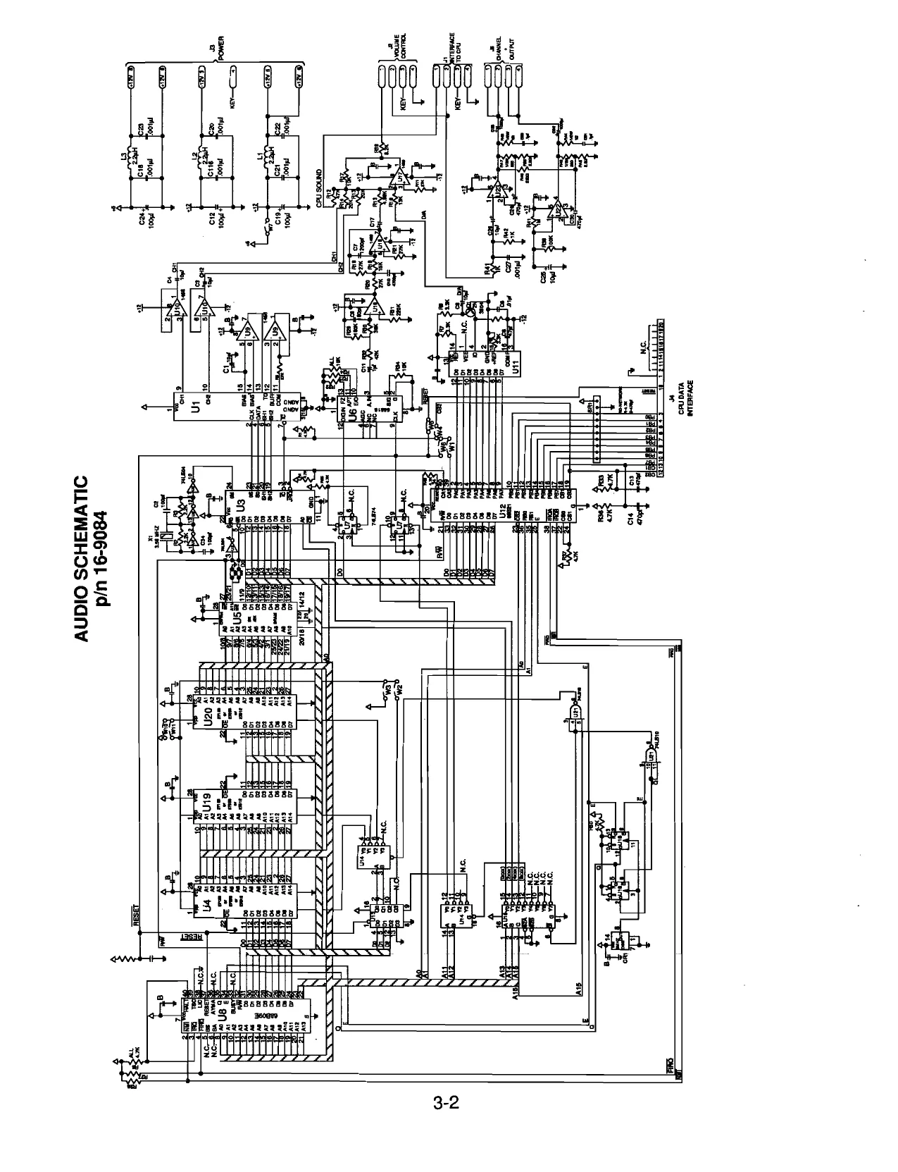
This page is a drawing, shown as the original scan.
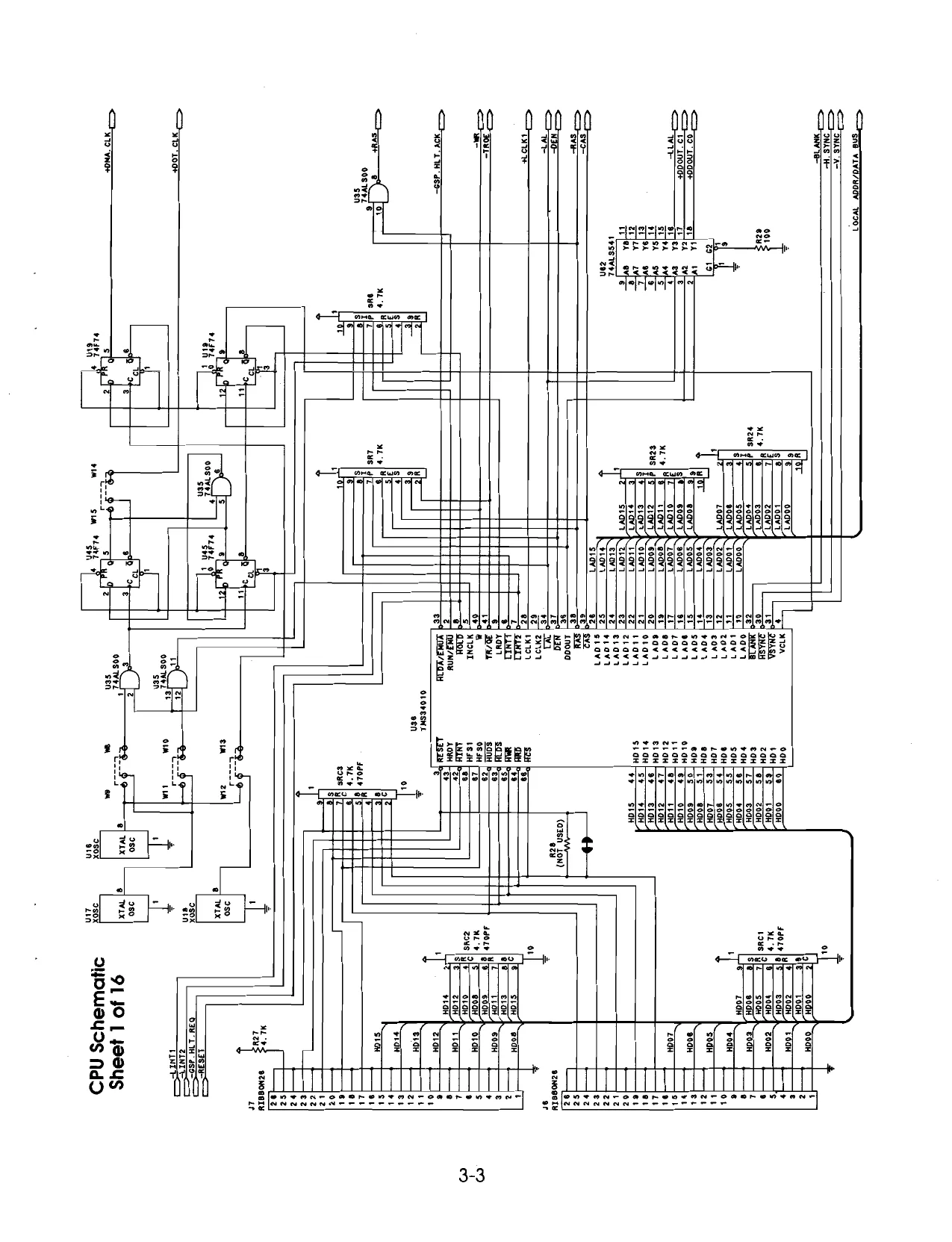
This page is a drawing, shown as the original scan.
CPU Schematic = st—ebr ADEE a0
Sheet 2 of 16 Aas
Ana tAeax war ti Loss. Love A07X. LAvex LAOSX, LA04X, LAgsx, ‘02x tAoix. r
cL RAS. roa lao. nas 1/041 Icas 1703 VW 1/02 1701 Lagex LAOSX ‘A04x LA03X, LAO2X, LAOS 99x. vee ae8 las tas tao. As 1/04 if
Looe Dos. L094 g g
= CAS. I
err SL ROE uss ancs73
use ‘TAALs245. ur TanLo24s. veo TAMLS245 j18_vors vey T4aus243
As 887 ora
‘AT lfie——vora
roomorsr 3) Gg
s0D0UT.co. =VDEN.H. en
This page reads as a drawing: its text was drawn rather than typeset, and comes out in fragments. See the original scan.
3-6 91 10 yeeus oyoueyss dd
3-7
CPU Schematic
Sheet 5 of 16 PROGRAN MEMORY
LOCAL_ADOR BUS LOCAL DATA BUS
LOCAL _ADDR/DATA BUS Lae AIT LANG! AIS LAY Lara LAY? LAM RAD 1 COIN. CNTR
ak vas. i 2064 q
3-8
CPU Schematic
Sheet 6 of 16 SRS uns. AUTOE RASE,
cc
t a +}
SONA SE SR24—10 9829-10 i . 4.7K i" 4.7K VIDEO pata BUS
3-9 LOCAL_DATA BUS.
CPU Schematic
Sheet 7 of 16 use vrs. uss ure TAALS245 _ TALS245 TaaLs24s T4as245
un TAALSSTS vss T4ALs245
fap =1ROE. TAL =IROE.T2L SIROE.TIL =IROE_TOL IDEN. =IDEN.L —
This page reads as a drawing: its text was drawn rather than typeset, and comes out in fragments. See the original scan.
This page reads as a drawing: its text was drawn rather than typeset, and comes out in fragments. See the original scan.
sors 798 sors bors 110% tors 198] ae Pros | aaa zors ae Fees z0spr qeae Yeois _“308bre4 reas —zz]tors, Wp feors sas ——z4) cos ers —zz]e0IS 0/UL by Hee——Frfrots at > ors eos #2] 9018 ease] vOrs AL Sean tort YA Lon “ara 1077 FER S]07E SYP a eS zon Tm —|zont Seah —a|207T Zeon ere YT xr ovn @4on Er] COT EAKKAN ean er]8OL Vanover Bean eT]8OE | Var ve Seanez] Ler xcovn Trane] 707" EE tan sqrot XEve Taner ava | eter ieove HEE iy xEovA a xEova Sire ova 90K FOV Ne xvovee NTT xsova XS0VA XSOVA Nir xsova. PM EOWA. ‘ XO0¥A XBOVA Mis ECOL ye LL xcova XLOVA XLOVA whe XLOVA ihe] —xaown ihe —xaove XaOvA Lhe} —“xeovne very Tory Tere een zen een
vO EEMLLLS X19 B¥OAS | a we tors bors tors Ce 3 cots S008 Fl pos ou0s ez] e018 ~ zz] e0rs ‘Side zz] O18 Tras ez] 9018 Ez] rors Tras ez] 9078 =| S07t {4071 3 1070 600, 3] 2071 9200 7600 3] 2071 000 ———#T] 807E EAXIAN ar] E071 EGY ‘zoo——61] 80/1 EIN OW $009 Bz] #071 X20VR Bz} 9071 ECON ‘e007 #071 KZOvA KEOWA
XEOvA XEOWA EOWA XEOVA q EGAN FOUN EUAN IS0VA SOV XSOVA XS0¥K EOUN FOUN SOK ECUZN EEN XLOVR XLOVR XLOWA aoe XG0VK Keon xa0vR
91 JO OL J9EUS OHOWSYSS NdD
3-12
This page reads as a drawing: its text was drawn rather than typeset, and comes out in fragments. See the original scan.
3-14 ry YoRAMCTL
: =SDEN CRW on : ODEN, DEN. EPeoo an
1B re Le
F ALINT2 4, z :
CPU Schematic
Sheet 12 of 16 Jans
#007. CLK. LOcAL_pAr,
CPU Schematic
Sheet 13 of 16 ves TSALSS74
3-15 we TSALS245,
cee spout. ct
3-16
CPU Schematic
Sheet 14 of 16 <v. SYNC =H. SYNC
COLOR DATA BUS
COLOR ADDR BUS __" “Be us ooo 6225664 RED. GUN
e444 (NOT USED) GAN, GUN
gegeeses ace ctor. cK. ws Syl ANK.X tt BL ANK.X iN2 spay 7407
97. 7407 aN 4 3407
q407 | a7 vay, 7407 {NOT USED) (NOT useD) R21 (Wor useD)
9L JO SL 4e0US SHOWIBUSS NdD ars]e1-1919]
3-17
om ke 2031 a7) snuvis 0K
ad ome 5; moor Ll mol wool mon m1 007 La 109° Te s9Te) Te Te +9 2
om ks sax at read WT DRS
a Danse oanse 7 * : Hi wre "aR 4 7 wn “Nu 4 tT — . [nee
- am 5 [arr : H WAS. 0x30 10x70 mi OF ne st * d H= f oa : mS 7
: ezingnts 52 rer Ur 4 ean
2 Faw , Z 7 weinawts : ‘veingnt— z 7 1 ‘ Eeinant L Seinaty : EaINS WOT ¢ int {orm { Me ezingnte : einai H 1 . 7 beinant & aeinaw ts IF WOO" 7 Teinawt— ‘eeingNT— s0x370" zux70N o1x370H cre v PEDTEESSS + ue rn z ae Singur WeorLtoay
, * nl ba a Per + + e .
aA z sa L 4 WE DaAS A _ [=]
0x370" Trans [tr HDW345/UIOd ONNOS a a )
9L 30 91 JeauS WIE TIES lanes SHOWAYDS Ndd DORE TR TOR ‘3ans= cP WE 2aAs% 1 —$_<rresans
Ey oznogery Bars ¥3: 3018 AN3NOdO2 er te i ‘SOVINTINE GwVOe GNNOS SOVHUINT WE
3-18
SMASH TV
Jamma Chart
| Function | Wire Color | i | i | Wire Color | Function |
GROUND BLK
| | | GROUND | GRN-BRN E- |
+5 VOLTS DC GRY
| _s8VOLISDC | | | GRY. |
- 5 VOLTS DC GRY-GRN 42 VOLTS DC GRYYEL BLK pe Bay SROUN GRY +5 VOLTS DC GRY 45 VOLTSDC -
GRY-GRN - 5 VOLTS DC
(oo GRV-YEL [> He VOLTS De KEY WHT-GRN COUNTERS NC GRAN-ViO | SPEAKER) NC GAN | VIDEOGRN WHT VIDEO SYNC eWHERED SEAVICE
WHT-VIO TILT
| YEL-BLU | : | 2 START |
YEL-BLK UP MOVE YEL-BRN DOWN MOVE
| ALERT MOVE | oO | ORGRED | °VEURED® | | | 2 LEET MOVE” | |
| 1 RIGHT MOVE | ORG > | ~ YEL-ORG | 2 RIGHT MOVE | |||
| OYUPFIRE | = ) oRGYeL | | 22 | LOO NELVIO | 2 | UP FIRE | |
| 1DOWNFIRE | =| | ORG-GRN | | : | YEL-GRY | 2 DOWN FIRE | |
| TLERTRIRE | oo | CORGEBLUD 8) | 2a | lb | VIO-BLK™ | OC RLERT FIRES |
1 RIGHT FIRE ORG-VIO VIO-BRN 2 RIGHT FIRE
| Ne | eee | | | oMORED | NOR |
NC NC
| BLK | copa | ppl | GROUND |
COUNTERS © t
_ SPEAKER (4) -
VIDEO RED | VIDEO BLU © NIDEO GND: SHIELD TEST GRN CONT WHreBLU
START 1 YEL-GRN
“UP MOVE: ORG-BLK © 1 DOWN MOVE ORG-BRN <xeccueavzerxesamooa>
3-19
This page carries no recoverable text. It is a drawing or a photograph. See the original scan.
SMASH TV POWER WIRING DIAGRAM 1 | [1 } BLK To ON/OFF = BACK DOOR 1/2 ||2-GBN —___—LigHT FIXTURE
| Cablepin: H- 19555 SWITCH | SWITCH | ‘ | ‘ | Wwe | > 60 Hz |
| fof BLY ir | Lwioa | 71/1 Lwioa | alfa |
| ViO-YELA |2||/2) ViO-YELA | 12 || 2
| | | | | | VIO B | 31/3| von | ails |
| o-ve.p |4||4|vio-vera
| u | 1 | 1 | TO | ||||
| “vel | t | EL WHT | =|2||2}GBN-YEL_ — MontTor | ||||
| SEE | Yet | 1] | /4 | 69 NACI | “13 | )]3 | Lwur |
TRANSFORMER 2||2 eon oor CHART 4
TRANSFORMER CHART
FROM POWER
| SWITCHES | 15 PIN CONNECTOR | 4 PIN CONNECTOR |
YEL 3 WHT
| =| 6 | WHT | 4 | 0 | Ogvio | 3 |
| € | ‘fivio | 11 $ | 120v isoLaTeD FOR | |||
| 3} | yl | 2A | MONITOR AND POWER | ||
| 12 | 15. | ¢ | -YEL 4 |, | SUPPLY | ||
| neve: | at | Heb — tae | p) | Sio= ver 2 1$ | |
| SHOWN AS | SEE | »|5 | BLU - WHT | 0 |
JUMPERED TAGE
| FOR | SELECTION | | 8 | BLU-BRN | 103.5 | YEL-WHT | 1 |
| 118VOLT | TABLE | " | BLU ELK | 116 | sev | 5.9V FOR COIN DOOR |
14] 5 Vea. Yel 2! ¢ | LIGHTS
| OPERATION) | XFMR 5610 - 12550 - 00 | < |
| II, | }7 | 2PIN |
| [>| 10] 3 | au | CONNECTOR |
| = | >| 13 | BLK |
TOPOWER WHT-BED |, | 2 WHT - RED
| SWITCHES _BLK- YEL | | 4 | LK - YEL | EROM LINE |
Voltage Selection Teble
5-6,7-8,10-9 5, §-6,7-11, 10-12 | 132 5-6,7-14, 10-15 207 §-9,10-8 218.5 5-9,10-11 230 5-12, 10-11 247 5-12, 10-14
3-21
do vo zr oL,
3-22 Bake beey (POST ON Pest) ION (Pes ION a * an preg puns uo w wats server a 38 H & eg ; fi auvog annos QUVO Ndd LINN-A «fz
o = ais qi AaRLELY E eps ne ol AWD AS bad [23 ion S12) 7eF
= aig r er Sm ce ra
ne ret) [vez biinoeezosvezi (@sasvect | Pr 1 oeen wee Qaee a zo 2 Els LYVHO WAYS B53 ee ! e Bp 29s sojauuog o8P3 YE veduine Rd ! i panes tne im
re) ‘=: poor 3 01 anoa
punoge mad puneg wed ONIYIM GuVvOdHyaINI AL HSVINS
Control Panel Wire Colors
PLAYER ONE
START/CONTINUE
Yellow-Green Black Black
MOVE & FIRE
Red Violet Orange-Brown Brown Black
PLAYER TWO
START/CONTINUE
Yellow-Blue Black Black
MOVE & FIRE
Red Violet Orange-Brown Brown Black
3-23
Smash TV Inserted Jumpers
AUDIO BOARD P/N D-11581-3044
CPU BOARD P/N C-13234-3044
NOTES:
~ WARNINGS & NOTICES
_ Warning ~ USE OF NON-WILLIAMS' PARTS OR CIRCUIT MODIFICATIONS MAY CAUSE SERIOUS INJURY OR EQUIPMENT DAMMAGE! USE ONLY WILLIAMS’ AUTHORIZED PARTS.
- For safety ond reliability, substitute parts and modifications are not recommended. oe
- Substitute parts or modifications may void FCC type acceptance. 3 |
- This game ls protected by federal copyright, trademark and patent laws, Unauthorized modifica 4 tlons may be illegal under Federal aw. This also applies to WILLIAMS’ logos, designs, publications and assermbiles, Moreover, facimiles of WILLIAMS equipment (or any feature thereof) may be illegal under federal law, regardless of whether or not such facimilies are manufactured with WILLIAMS’ components.
Warning
This equipment generates, uses and can emit radio frequency. energy and, if not installed properly and used according to the directions in this manual, may cause interference to radio communications. I has been tested and found to comply with the limits fora Class A computing device pursuant to Subpart J of part 15 of FCC rules which are designed to provide reasonable protection against such interference when operated in a commercial enviroment. Operation of this equipment in aresidential area is likely fo cause interference to radio communications, in which the user, ai his or her Own expense, will be required to take whatever measures may be needed to correct the interference.
“Waring Prevent shock hazard and:assure proper game operation, Only plug this game into 4 properly grounded outlet. Do not use a cheater plug to defeat the power cords grounding pin: Do not cut off the ground pin,
Notice _ No part of this publication may be reproduced by any mechanical , photographic, or electronic process, or in the form of a phonographic recording, nor may be transmited, or otherwise copied for public or private use, without permission from the publisher,
Entite contents of this manual copyright © 1990 WILLIAMS ELECTRONICS GAMES, INC, All tights. reserved
WILLIAMS ELECTRONICS GAMES, INC, ©
2 3401 N. CALIFORNIA AVE. 3 CHICAGO, ILLINOIS 60618