Asteroids Caberat DP-155-1st-01A
Asteroids (rev 4) (Atari, 1979) · Drawing Package · 1 pages · original scan
VIDEO POWER SUPPLY WIRING DIAGRAM (034633-01 © B)
ch | eee Moos test ber) solse7 es
_teaved oxy o3v00)
Drawing Package Supplement
to
ASTEROIDS/CABARET
Operation, Maintenance, and Service Manual
Contents of this Drawing Package
Game Wiring Diagram, Coin Door and Power Supply Sheet 1, Side A Microprocessor Sheet 1, Side B Video Generator Sheet 2, Side A ‘Switch Inputs, Coin Counter, LED and Audio Outputs: Sheet 2, Side B
A. ATARI
(© 1979 Ata ne.
Sheet 1, Side A DP-155.01 tat printing © Geitnen covone he racows! oie Buned Wee foc}, Gnd Seen one 2aniS), Avo Sue twiTe Wie (neue
TERE ois crore yin revion REGULATORIAUDIO PCB SCHEMATIC (034485-01 D)
Regulator/Audlo PCB 02448601 A
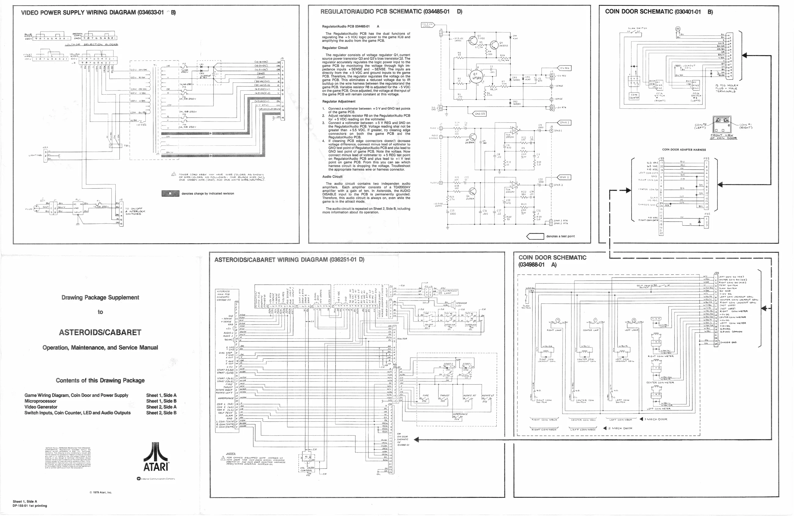
The RegulatoriAudio PCB has the dual functons of regulating the +5 VOG logic power to the game FB and lying the audio from the game PCB.
Regulator Circuit The regulator consists of voltage regulator Q1, current ‘source power transistor QS and Q2's bias transisto’22. The regulator accurately regulates the logic power inpu to the ‘game PCB by monitoring the voltage through tigh im Pedance inputs +SENSE and —SENSE, The inputs are ‘itectly from the +5 VDC and ground Inputs to tte game PCB. Therefore, the regulator regulates the voltage on the ‘game PCB. This eliminates a reduced voltage die to IR. buildup on the wire hamess between the regulatorand the ‘game PCB, Variable resistor PB is adjusted for the -5 VOC. ‘on the game PCB. Once adjusted, the voltage at the nput of the game PCB will remain constant at this voltage.
Regulator Adjustment
- Connect avoltmeter between +5 V and GND tet points ‘of the game PCB.
- Adjust variable resistor R8 on the Regulator/Autlo PCB for +5 VDC reading on the voltmeter.
- Connect a voltmeter between +5 V REG and 3ND on the RegulatoriAudio PCB. Voltage reading shal not be greater than +55 VOC, If greater, try cleaniig edge Connectors on both the game PCB aid the RegulatorAudio PCB, I cleaning PCB edge connectors doesn't cecrease voltage difference, connect minus lead of voltneter to GND test point of Regulator/Audio PCB and plu: lead to GND test point of game PCB. Note the voltaye. Now Connect minus lead of voltmeter to +5 REG tet point fon Regulator/Audio POB and plus lead to +! V test point on game PCB. From this you can sei which harness circuit is dropping the voltage. Troutleshoot the appropriate hamess wire or harness connestr. ‘Audio Circuit
The audio_circuit contains two Independen audio amplifiers. Each amplifier consists of a TD/2002AV amplifier with again of ten. In Asteroids, the AUDIO DISABLE Input to the PCB is permanentiy gounded Therefore, this audio circuit is always on, even vile the ‘game isin the attract mode, ‘The audio circuit is repeated on Sheet 2, Side B, licluding ‘more information about its operation.
ASTEROIDS/CABARET WIRING DIAGRAM (036251-01 D)
| szaar deo) | Gar vaca, sraar 1940} Sinan shea
frome teer
cow e ene)
Sonn (nes
| e'Sem fen) ES eur) < onotes a test point COIN DOOR SCHEMATIC (030401-01 B)
[eon] koa)
Icom *, eau)