Asteroids Deluxe DP-165-2nd-02A
Asteroids Deluxe (rev 3) (Atari, 1980) · Drawing Package · 1 pages · original scan
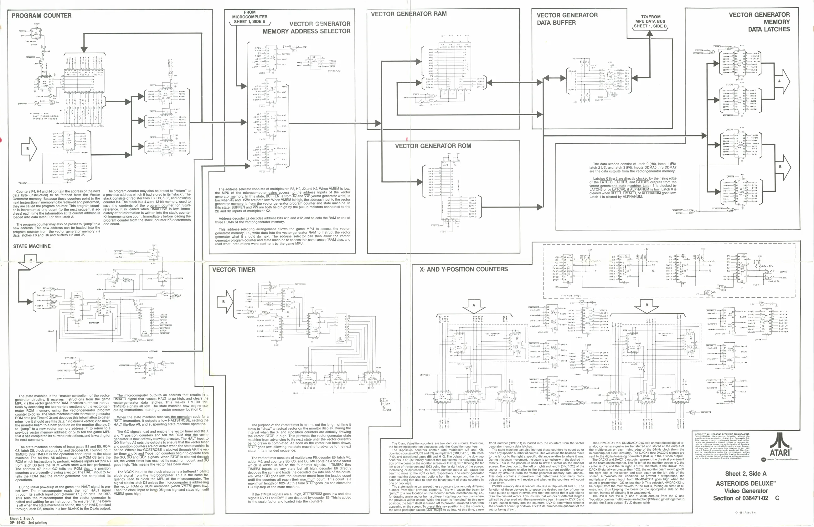
FROM MICROCOMPUTER sane VECTOR GENERATOR MEMORY ADDRESS SELECTOR PROGRAM COUNTER VECTOR GENERATOR RAM VECTOR GENERATOR DATA BUFFER VECTOR GENERATOR MEMORY DATA LATCHES TO/FROM MPU DATA BUS SHEET 1, SIDE B
The data letches consist of latch 0H), latch 1 (F8), = latch 2 (J6), and latch 3 (K6). Inputs DDMAG thru DDMA7 are the data cutputs from the vector generator memory. J
Latches 0 thru 2 are directly clocked by the rising edge of the LATCHO, LATCH, and LATCH? outputs trom vector generators state machine. Latch 3 Is clocked by ‘or by LATCHO, if ALPHANUM is low. Latch 0 is cleared when RESET, DMAGO, or ALPHANUM goes low. Late 1 is cleared by ALPHANUM, ‘The address selector consists of multiplexers F2, H2, J2 and K2. When VHEM is low,
| the MPU of the microcomputer | gains | access | to the | address inputs of the vector |
‘generator memory. n this state, is from ®2 and VW (vector generator write) is this state, ‘and VW are both held high by the pullup resistors connected to the
Tow when 82 and RAW are both iow. When VMEM is high, the address input to the vector {generator memory is from the vector generator program counter and state machine. In
2B and 38 inputs of multiplexer K2. Counters F4, H4 and J4 contain the address of the next ‘The program counter may also be preset to “return” to ‘data byte (insiruction) to be fetched from the Vector a previous address which it had stored in its “stack”. The ‘Generator memory. Because these counters point to the stack consists of register files F3, HS, & J3, and downlup ‘next instruction in memory to be rettioved and performed, counter KA. The stack is a 4word 12-bit memory, used 10 they are called the program counter. Thi ‘save the contents of the program counter for future eripinoremented one-eount to the next soguontial ad reference. tis loaded when OMAPUSA ts low. Immo. ress) each time the information at its current address is diately after information is written into the stack, counter loaded into data latch 0 or data latch 2 é increments one count. Immediately before loading the
program counter from the stack, counter KS decrements
The program counter may also be preset to “jump” toa one count. new address. This new address can be loaded into the ‘program counter from the vector generator memory via ‘ata latches FS and H6 and buffers HS and JS. sopl—= ‘Address decoder L2 decodes address bits A11 and A12, and selects the RAM or one of, three ROMS of the vector-generator memory. ‘This address-selecting arrangement allows the game MPU to access the vector: ‘generator memory, Le., write data into the vectorgenerator RAM to instruct the vector Generator what it/should do next. The address selector can then allow the vector ‘enerator program counter and state machine to access this same area of RAM also, and ‘ead what instructions were sent to it by the game MPU. ‘STATE MACHINE
VECTOR TIMER
ieee sn nee i
‘The state machine is the “master controller” of the vector- The microcomputer outputs _an address that results i) a ‘generator circuitry. it receives instructions from the game OMAGO signal that causes HALT to go high, and clears the MPU, via the vector generator RAM. It carries out these instruc- vector-generator data latches. This makes TIMERO thru tions by accessing the appropriate sections of the vectorgen- TIMERS signals all low. The state machine now begins cxeerator ROM memory, using the vectorgenerator program cuting instructions, starting at vector memory location 0.
‘counter to do 0. The state machine reads the vector-generator
FIOM data via Timer0-3) and decodes this information to deter- _When the state machine receives the operation code for a ‘mine how it should use this data: 1) to draw avector,2)t move HALT instruction, it outputs a low setting the {the monitor beam to a new position on the monitor display; 3) HALT tlipop A9, and suspending state machine operation. to “Jump” to a new vector memory address; 4) to return to a previous vector memory address; or 6) to tell the game MPU _The GO signals load and enable the vactor timer and the X {hat it has completed its current instructions, and is waiting for and Y position counters and tell the ROM that the vector Its next command. ‘Generator is now actively drawing a vector. The HALT input to Go fipslop A9 sets the outputs to ensure that the vector tiner ‘The state machine consists of input gates B8 and ES, ROM and position counters are not active when the state machine is ‘The purpose of the vector timer is to time out the length of time | takes to “draw” an actual vector on the monitor display. During the interval when the X- and Yposition counters are actually drawing the vector, STOP is high. This prevents the vector generator state machine from advancing to its next state until the vector currently being drawn is completed. As soon as the vector has been drawn, ‘900s fow, allowing the state machine to advance to the next
| ‘The X-and positon counters are two identical circuits Therefore, | 12bit number (OVXO-T) Is loaded into the counters from the vector | __The UNMDAGXT they UNMDACX10 (X-axis unmultiplexed digita-o- | ||||||||
| following description discusses only the X-position counters. | generator memory daa latches. | analog converter signals) are tansterted and stored atthe output of | ||||||||
| C8, latch D8, clock circuitry A6, and decoder E8. Four-bit input halted. When alow GOSTROBE is clocked through A9, the vec | tate in its. | ded | edge | odes | ||||||
| State | inte | intended | sequence. | “a Xeon cours conan io uplee C8 and KB, | Tho sat machine can sie act these counters to count up or | te mulipexs | each a | cock | from | pone |
| Tino Vv TIERS she operate apt ote sate torte and an Y oston enue | bai operate fn | Ie ee ee a | ee eae, | erat | enn carn actosaee | | | ee cee | omea ee | ATARI" | ||
| Imachine, The Ad thu AB address input To | ROM C2 tals the the GO, GO and GO” Signals. When STOP sciocked | though | The vector timer consists of multiplexer F5, decoder E6, latch M6, | (Foy and astociaod gates (68 and Hi), The output of the Cownlsp | tothe let orto the right a speciic distance relate to where it was, | sent to the cigiato-anaiog converters (OACa) in the X vdeo output | cetreaeons | |||
| {counters Is a 120i binary number that represents the horizontal loca- | During this beam movement, th beam Is turned on withthe desired | The OAGX1 and DAGX10 outputs represent the physical placement | “hin | sm | fet ei | [eee | |||||
| tion of the beam on the monitor screen (or Xaxish with being the far | tensity. Ths isthe procedure used to draw a vector on the monitor | of the beam on the monitor. The fr lft ofthe monitor sere 0, the | ||||||||
| loft side of th Soreen and 1023 being the fa right side of the screen, | Screen, The direction (tothe lll or right) and length (to 1025) of the | center is S12, and the far right is 1023, Therefore, ifthe DACKS thru | ||||||||
| Increasing or dscreasing tis binary number output wil cause tho | vector to be dawn rolative to the bear's current position is deter. | DACXI0 signal was greater than 1023, the monitor beam would go off | ||||||||
| ‘beam to hows to the right or lel, respectively. The vector generator | mined by OVXO-1T (rom the vector gonerator memory data latches). | the right side of the | screen and start again on the lft side ofthe | |||||||
| sig | met | cecodes sce om eam | andthe i-ca | Ti aa coven ioatn iat Gains Raw many cok | stem a “wpa | conn, To pet | wraparound |
feof using (oa ROM which instructions to perform. Address inputs AO thru A3 AQ, the vector timer has reached its maximum count, and {rom latch 08 tells the ROM which state was last performed. goes high. This means the vector has been drawn. ‘The address A7 input GO tells the ROM that the position ‘counters are presently drawing a vector. The HALT input to A7 The VGCK input to the clock circuitry isa buttered 1.5.MHz {ells the ROM that the vector generator has completed its clock signal from the microcomputer. This is the same tre- ‘operations. ‘quency used to clock the MPU of the microcomputer. The ladder MS, and counters B6, C8, and D6. M6 contains a scale factor Which is added in M5 to the four timer signals. If TIMERO thru TIMERS inputs are any state but all high, decoder E6 directly {decodes the sum and loads the decoded low into one of the count fers. When GO goes iow, the counters count from the loaded count Until the counters all reach their maximum count. This count is a Sheet 2, Side A
| sree uate atch OS unless the mlorosomputarta ekeeaog | Me | esa an | a ee | aes | Tae ee | ; | ne binary COUN | ofthese countrs im pues tho countors wl cae and whether he counts wil Sount | multiplexers select input trom UNMDAGXTT goes igh when the | ||
| 5 | imum | length | o | ist | oes low and cl | ne of two wi. | tpordown | ‘Counts gear han 1029 or ess | than O- | This aolcte ONMDRCRTD | ™ |
| During inital powerup of the game, the HALT signal is pre- the vector RAM or ROM memories (when VMEM goes lw) | GO tiptop ofthe state machine | “ia sia mcine an preset hase counters to | anentisy diternt | “POVA09 memory dala loaded it ae multipin | J8 and KB. hoe culpa | tne mulpexe tothe OA, | cng al anos o | ASTEROIDS DELUXE’ |
set low. The microcomputer reads’ the high HALT signal Then the clock input to latch D8 goes high and stays high unt through ite switch input por (selmux L10) on data line O87. VMEM goes high ‘This tells the microcomputer that the vector generator Is halted and wating for an instruction. To ensure thatthe beam is off when the state machina Is halted, the high HALT, clocked through latch D8, results in alow BLANK to the Z-axis output. ‘number trom their previous contents. This wil cause the Beam to 30 devices isto space the desied number of counter ones, and thus Keeping the beam on the appropriate side on the “jump” toa relocation on the monitor sereen instantaneously, Le, ‘over the time period that will take to Screen, instoad of allowing it to wraparound. {or drawing anew vector rom a diferent starting position than wire inures that vectors of ciferant lengths The XVLD and YVLD and Y vald) Outputs from the X- and
| the previous restor | ended, While | the beam fs “jumping to this new | willstilbe displayed with he same relative boam intensity | OVX10 and | position counter multiplexers are latched (F 10) and gated together to |
| positon, the eam itself tured of to prevent Unwanted lines from | 11 are loaded directly into the counters. DVX10 determines whether | enable the Z a's output, BVLD (beam vali. |
‘Sppearing onthe screen, To preset ihisnew postion Into the counters, the counters count up or down, OVX determines the Quadrant ofthe the state goarator causes (ago ow. At this tine, anew vector being drawn Video Generator Section of 03647102 C It the TIMER signals are all high, ACPHANUW goes low and data signals DVX11 and DVY11 are decoded by decoder E6. This is added to the scale factor and loaded into the counters.
(©1801 Aan, ne ‘Sheet 2, Side A DP-165-02 2nd printing