10 Yard Fight (72-00049-001)
10-Yard Fight (World, set 1) (Irem, 1983) · Manual · 45 pages · 7 sections · original scan
oj © 1984 Trade Marks of Taito America Corporation 72-00049-001
r © 1984 Trade Marks of Taito America Corporation 72-00049-001
This page carries no recoverable text. It is a drawing or a photograph. See the original scan.
“10-—YARD FIGHT”™ TABLE OF CONTENTS
- “TEN—YARD FIGHT”™ A. GAME FEATURES ............. 000 cece eee teens 1 B. INTRODUCTION ..... 2.0... cece cee eee 1 C. GAME INSTALLATION .......... 00 0c cece eee eee eee 1 D. DIP SWITCH AND VOLUME CONTROL SETTINGS ........... 1-3
- MAINTENANCE A. CLEANING ... 0.2. 3 B. FUSE REPLACMENT ........... 06. c cece eee eee 3 C. VIDEO MONITOR REMOVAL .........-. 006 cece cece eee eens 3 D. PRE GAME INSTALLATION .... 0.2.0.0 0c c eee cence eens 4 E. COVERGLASS REMOVAL .......... 0.6 cece cece eee eens 4 F. PRINTED CIRCUIT BOARD REPLACEMENT .................. 4
- DIAGNOSTIC PROCEDURE ................. 0... cece eee e eens 5-6
- ILLUSTRATION & PARTS LISTS INCANDESCENT PANEL ........00.-000ccee eee eeees 7 8-WAY JOYSTICK ..00. 0.00 cece ccc cece cence canes 8 CONTROL PANEL... 1.2.0... 0 cece cence eee e cence 9 DOOR ASSEMBLY SUC-3 20.0... . ccc cece cece eens 10 COIN DOOR 0.0... cece cece cece nee e eee e nn ees 11-12 COIN DOOR 0... 0c cece cece cece eee e eee e ee ees 13-14 COIN DOOR 20... ccc c cece ccc cece eect en eens 15-16 CABINET ASSEMBLY REAR VIEW ............... 17-18 CABINET ASSEMBLY FRONT VIEW .............- 19-20 POWER SUPPLY COMPONENT LAYOUT .......... 21-23 POWER SUPPLY SCHEMATIC 1 of 1............05. 24 FILTER BOARD ......00. 000 c ccc cece e eee eee enees 25 TOP PCB (M52-Sound) ........... ccc cece eee e eens 26 TOP PCB (M52-Sound G) ........ 00 ccc ee eee eee ee 27 TOP PCB (M58-A-A) 0.2.00. cece cece eee eee e eens 28 CENTER PCB (M58-A-A) 4 BOARD SYSTEM ...... 29-32 BOTTOM PCB (M58-B-A) ...0...0 00. cece eee eee e eee 33 BOTTOM PCB (M58-B-A) 5 BOARD SYSTEM ...... 34-38
- WIRING DIAGRAM FOLDOUT
“10-YARD FIGHT”™ UPRIGHT
- GAME SET-UP
A. GAME FEATURES TAITO AMERICA CORPORATION’S “10-YARD FIGHT”™ upright game is housed in a compact and highly serviceable cabinet with many added features. A larger designed cash box has been incorporated into the design of this cabinet. By putting wheels on the cabinet, moving the game from one location to another is made much easier. The Control Panel has a polycarbonate overlay, so cigarette marks and mars can easily be wiped clean. This overlay can be replaced if necessary. The Marquee and Coverglass are made of fully Tempered Glass to minimize breakage. The Back Service Door houses all the P.C. Boards for the system making servicing of the game, if needed, much easier. Lighted instructions are provided to further enhance the game and attract players, by making the instructions easier to read. B. INTRODUCTION “10-YARD FIGHT™” is a fast moving football game licensed by Irem Corporation exclusively to Taito America Corporation. “10-YARD FIGHT™" can be played by one or two players. “10-YARD FIGHT™” lets all the armchair quarterbacks take the field, take the ball and take as much action as they can handle. The player must score a touchdown in the time allotted to go from high school and college ball all the way to the Pros and the Super Bow! with cheerleaders marking his progress in-between. Each level begins with the player carrying the ball on the kick-off as far up the field as he can before being tackled. Then he’s in control as quarterback, running with the ball or throwing a forward pass to or lateral to a receiver who lets him know he’s open by waving his arms. An intercept pass means a 20 yard penalty, points after can be scored by kicking the ball or running with it into the end zone and the clock is stopped when the player runs out of bounds. “10-YARD FIGHT™” has a continuous play feature whereby the player can continue to play where he left off by inserting an additional coin. So be the next All American Footbal Hero - Play “10-YARD FIGHT™". Good Luck! C. GAME INSTALLATION TAITO AMERICA CORPORATION'S “10-YARD FIGHT”™ upright game is shipped ready for operation, but a last visual check should be made to insure the game is in good condition. Please verify the following before turning the game on. Check the exterior of the game for shipping damage, chips, dents, or broken parts.
- Open the Rear Service Door and check for any interior damage.
- Make sure there isn’t any damage to the wiring.
- Check the Printed Circuit Boards, making sure there is no damage to the components.
- Check fuses to make sure they are firmly in their holders.
- Check for loose foreign objects, especially metal objects which may cause electrical problems.
- Check Plug-in Connectors making sure they are firmly in their sockets.
- Check Switches making sure they are not damaged. The Video Monitor is properly adjusted before shipping. If there are any adjustments necessary, refer to our Video Monitor Manual (72- 00025-001). This manual contains all the manufacturers recommendations for adjusting the video monitor. POWER REQUIREMENTS TAITO AMERICA CORPORATION'S “10-YARD FIGHT”™ upright game is shipped ready for operation at 120VAC, 60Hz with a power consumption of approximately 250 Watts.
CAUTIGN For safe operation it is recommended the cabinet be grounded. This game is equipped with a three conductor power cable. The third conductor is the ground conductor and when the cable is plugged into an appropriate receptacle the game is grounded. The offset pin on the power cable's three-prong connector is the ground connection.
LOCATION SPACE Depth 35” (87.5cm) Width 24” (61cm) Height 68” (171cm) Weight 300 Ibs. (Packaged Weight) D. DIP SWITCH AND VOLUME CONTROL SETTINGS
DIP SWITCHES TAITO AMERICA CORPORATION'S “10-YARD FIGHT"™ game provides the following option switches. See Figure 1. These option switches can be found on the Game Board (99-AA017808).
VR-MAIN ]
_t 2 1 i frame) fund = | pPsw = = = !
“10-YARD FIGHT” DIP SWITCH ADJUSTMENTS
DIP SWITCH 1
| OPTIONS | SWITCHES | 1 | 2 | 3 | 4 | 5 | 6 | 7 | 8 |
| TIMER | NORMAL | OFF | OFF | |||||||
| SPEED | X13 | ON | OFF | |||||||
| BETWEEN | X15 | oFF | ON | |||||||
| PLAYS | X18 | ON | [ON | ||||||
| eo | 1COIN/1 PLAY | OFF | OFF | |||||||
| MODE 2 | in 2 | 2 COINS/1 PLAY | ON | OFF | ||||||
| Dip‘switeH 2 | 3 | 3 COINS/1 PLAY | oFF | ON | ||||||
| posirion3 | |= | FREE PLAY | on | ON | ||||||
| ON | ERS | 1 COIN/2 PLAYS | OFF | OFF | ||||||
| a2 | 1 COIN/3 PLAYS | ON | OFF | |||||||
| S | 1 COIN/5 PLAYS | ie | OFF | ON | ||||||
| o | cy | 1 COIN/6 PLAYS | Ways | ON | ON | |||||
| S | 1 COIN/1 PLAY | OFF | OFF | OFF | OFF | |||||||
| = | 2 COINS/I PLAY | OFF | ON | OFF | OFF | OFF | ||||||
| g| | MODEL | 3 COINS/1 PLAY | orF | ON | OFF | OFF | ||||||
| @|_ | DIP SWITCH2 | 4 COINS/1 PLAY | ON | ON | OFF | OFF | ||||||
| Fr | POSTION 3 | 5 COINS/1 PLAY | OFF | OFF | ON | OFF | |||||||
| S| | OFF | 6 COINS/1 PLAY | ON | OFF | ON | OFF | ||||||
| ba | 1 COIN/2 PLAYS | OFF | OFF | OFF | ON |
1 COIN/3 PLAYS ON | oFF | oFF | ON 1 COIN/4 PLAYS OFF | ON | OFF | ON 1 COIN/5 PLAYS ON | ON | OFF | ON 1 COIN/6 PLAYS OFF | OFF | ON | ON FREE PLAY on | on | on | ON CONTINUED PLAY ves 7 NO OFF
DIP SWITCH 2
| OPTIONS | SWITCHES | 1 | 2 | 3 | 4 | 5 | 6 | 7 | 8 |
PLAYER 2 OFF SCREEN INVERSION PLAYER 1 ON
| CABINET TYPE | i | - | OFF |
UPRIGHT ON.
| COIN MODE | MODEL | ore | _|At- | AL- |
| MODE 2 | Lon | _|WAYS | WAYS | |
| asi | orr | [OFF | ||
| FREEZE PICTURE | FREEZE | ON | OFF | |
| HIT MODE | NORMAL | OFF |
NO HIT ON TEST MODE NORMAL OFF TEST ON
VOLUME CONTROL SETTING The Volume increases by turning the potentiometer as indicated in Figure 2. VOLUME CONTROL LOCATIONS
POWER ON/OFF SWITCH The power on/off switch is located in the front lower left hand corner of the cabinet.
- MAINTENANCE. All games require a certain amount of maintenance to keep them in good condition. A periodic check of mechanical controls would be benefical to guarantee your game will be profitable. A. CLEANING The exterior of the game, all metal parts and all plastic parts can be cleaned with an non-abrasive cleanser. Caution should be used when cleaning the plastic, a dry cloth can cause scratches and result in a foggy appearance. B. FUSE REPLACEMENT This game contains 8 fuses. Seven of these fuses can be found ‘on the Power Supply Assembly, five (5) are on the PCB and two
- are on the Power Supply Bracket. One (1) is located at the bracket where the AC line cord comes into the cabinet. See Figure 3 for location of these fuses.
FUSE REPLACEMENT C. VIDEO MONITOR REMOVAL If you need to remove the Video Monitor follow the instructions listed below:
NOTICE:
“This equipment complies with the requirements of Part 15 of FCC Rules for a Class A computing Device. Operation of this equipment in a residential area may cause unacceptable interference to radio and T.V. reception requiring the operator to take whatever steps are necessary to correct the interference.”
- Turn game power switch off.
- Disconnet the power from the line voltage.
- Make sure back door is open fully.
- Disconnect the Monitor cable connector.
- While holding the monitor bracket take out the two rear side bolts, one on each side of the cabinet.
- Carefully lower the monitor on to monitor stops.
- Remove the four mounting bolts and disconnect the braided ground wire.
- Slide the monitor out by pulling the monitor toward you.
Use extreme caution and do not touch electrical parts of the Monitor Yoke area with your hands or with any metal object in your hands! High voltages may exist in any Monitor, even with power disconnected.
MONITOR REMOVAL
D. PRE GAME INSTALLATION The following precautions should be followed when installing the game.
- Avoid rough handling of the game, the picture tube is fragile.
- Install the game on a level surface.
- Avoid installing the game where it may receive excessive sunlight or heat, to protect the game from rising internal temperatures.
- Do not install in a damp or dusty location.
- For a short time after connecting the power to the game, the picture may be temporarily distorted. The monitor's purity is atfected by the earth's magnetic tield, causing a variation of color. By turning the game on for 10 to 15 seconds and then off for 20 to 30 minutes, the automatic degaussing circuit applies a degaussing field to the edges of the monitor. Doing this several times will correct the problem. Another way to correct this problem is to purchase a degaussing coil or bulk tape eraser at any Electronics store. This will help to immediately demagnetize the Video tube. Caution must be used with a degaussing coil so the magnetic field of the degaussing coil is not allowed to become too intense at any one place on the picture tube thereby causing a localized color distortion. If you move the game to another location after degaussing the problem may reappear. Refer to Monitor Manual. E. COVERGLASS REMOVAL To remove the Coverglass follow the Instructions listed below:
- Remove the contro! panel by reaching up through the Coin Door and unlatching the latching clamps.
- Disconnect the Control Panel Cable.
- Lift the Control Panel out. The Coverglass can now be easily removed from the front of the game with no screws. To replace the coverglass simply reverse the above procedure.
- Open the rear service door, the power will automatically be removed by the Interlock Switch located on the inside of the door frame. .
- Disconnect the connectors G, H and T from the boards.
- Loosen and turn the Stop Bracket and slide the boards out of the board guides.
PRINTED CIRCUIT BOARD REPLACEMENT
- Test Mode
The Diagnostic program is activated by turning switch 8 of Dip Switch 2 to the ON position and turning the power switch ON. This diagnostic program is composed of 8 independent tests, the first two (RAM test and ROM test) of which initiate automatically as the power switch is turned ON. After these two tests end, the video monitor will display a list of the next six tests as described below when the 2-Player button is pressed: 01 DIP SWITCH 02 1-0 PORT 03 SOUNDS 04 CHARACTER 05 COLOR 06 CROSS HATCH PATTERN
Move the joystick to position the cursor at the desired test and press the 1-Player button to start the test. To return to test list: Press the 2-Player button (except when 02 I-O PORT test ends). As 02 |-O PORT test ends, move the joystick left (the 1-Player joystick for table type game) while pressing the 2-Player button. When all the necessary testing is complete, turn power switch OFF and turn switch 8 of Dip Switch 2 to the OFF position. A. RAM TEST
If RAM is OK, “RAM OK” appears on the video monitor. If RAM is at fault: “RAMNG — XXXX YY zz”
XXXX RAM ADDRESS
YY RAM input data ZZ RAM output data key Press the 1-player button to continue RAM TEST or
Press the 2-Player button to end this test and advance to ROM TEST.
B. ROM TEST
If the ROMs are OK, the following appears on the video monitor. RAM OK ROMO OK ROM 1 OK ROM2 OK ROM 3 OK
If any of the ROMs are at fault, for instance, ROM 1, the following appears on the video monitor. C. DIP SWITCH TEST When the video monitor displays the test list, control the joystick to position the cursor at 01 and press the 1-Player button. This test shows the state of switches of Dip Switch 1 and 2 and the results of game adjustments. 1=0N 0 = OFF
| DIP | SW | 1 | 2 | 3 | 4 | 5 | 6 | 7 | 8 |
| osWw1 | 0 | 0 | 0 | 0 | 0 | 0 | o | 0 | |
| DSW 2 | 0 | 0 | 0 | 0 | 0 | 0 | 0 | 1 |
TIME REDUCED BY DEAD BALL NORMAL
COIN MODE SELECTOR A 1 COIN 1 PLAY SELECTOR B 1 COIN 2 PLAYS
CABINET TYPE UPRIGHT
D.I-OPORTTEST While the video monitor displays the test list, control the joystick to position the cursor at 02 and press the 1-Player button. This test checks if all the switches on the Control Panel and Coin Doors are working correctly. The following display appears.
RAM OK ROMO OK ROM 1 NG ROM 2 OK ROM3 OK
ROM LOCATION TABLE MEMORY. LOCATION TABLE # LOCATION RAM 3 ROMO 3R ROM 1 3N ROM 2 3M ROM 3 3K 1=0N 0 = OFF
| TY | 2 | 3 | 4 | 5 | 6 | 7 | 8 | |
| KEY 0 | 0 | 0 | 0 | 0 | 0 | 0 | 0 | 0 |
| KEY 1 | 0 | 0 | 0 | 0 | 60 | 0 | 0 | 0 |
| KEY 2 | 0 | 0 | 0 | 0 | 0 | 0 | 0 | 0 |
*TIMING 0000
*TIMING starts at 0000 and adds one count approximately every second.
KEY 1-Player Button . 2-Player Button . Service Switch . Coin Switch A . P1 Joystick right P1 Joystick left P1 Joystick down . Pl Joystick up P1 Forward Pass Button P1 Sideways Pass Button . P2 Joystick right . P2 Joystick left . P2 Joystick down P2 Joystick up **Coin Switch B . P2 Forward Pass P2 Sideways Pass **Coin Switch B is for coin doors with two coin selectors of different values.
P2 Switches are for cocktail table games only. To terminate this test and bring the test list back to the video monitor, move the joystick left while deprressing the 2-Player button. KEY
KEY
E, SOUND TEST While the video monitor displays the test list, control the joystick to position the cursor at 03 and press the 1-Piayer button.
A table of sound appears on the video monitor.
01 BALL KICKING SOUND 02 LINEMAN BLOCKING SOUND 03 BLOCKING SOUND 04 TACKLING SOUND 05 GAME OVER SOUND 06 CHEER 1 07 CHEER 2 08 QUARTERBACK CALL 1 09 QUARTERBACK CALL 2 10 REFEREE CALL 1 ll REFEREE CALL 2 12 JUMP TACKLE VOICE 13 WHISTLE SOUND 14 TIME OVER INSERT COIN 15 SNAPBACK SOUND 16 BALL PASSING SOUND 17 OPENING MUSIC 18 GAME OVER MUSIC 19 BALL CARRIER RUNNING 20 CHEERLEADER MUSIC 21 TOUCHDOWN MUSIC
Select a sound by positioning the cursor with the joystick. Depressing the 1-Player button repeats the sound.
F, CHARACTER TEST While the video monitor diplays the test list, control the joystick to position the cursor at 04 and press the 1-Player button.
The video monitor displays four players carrying the ball which are flippea vertically and horizontally as shown below.
ROR
% 8 While the video monitor displays the test list, control the joystick to position the cursor at 05 and press the 1-Player button. G. COLOR TEST
This test is comprised of five independent checkups. Pressing the 1-Player brings each checkup to the video monitor.
- A row of letters A thru Z appears along with a row of numbers 0 thru 9 as shown below.
ABCDEFGHISKLMNOPQRSTUVWXYZ 0123456789
- Blue field is displayed.
- Red field is displayed.
- Green field is displayed.
N39ONVAD ama aay Wowie MOTTSA YNId NEER |) wove
- Color pattern appears on the video monitor as shown above.
H. CROSS HATCH PATTERN TEST Control the joystick to position the cursor at 06 and press the 1-Player button.
Across hatch pattern is displayed as shown below.
16 lines
TT
{_f 1 r {—
r =
1 in [
—1+— |_| c ;
INCANDESCENT PANEL
TAITO ITEM PART NO. DESCRIPTION
1 LAMP #47 27-00006-001
268B00009-001 BAYONET BASE SOCKET [61000112-001 MARQUEE LIGHTING PLATE
8-WAY JOYSTICK (63-00032-006)
TATIO ITEM — | PART NO. DESCRIPTION 1 63B00031-001 | BALL & SHIFT 63A00033-001 | MASK 63C00027-001 _|MOUNTING PLATE 62A00002-001 _|SHOCK MOUNT PLATE 63A00028-001 _| SWITCH PLATE 63A00030-001 _|ACTUATOR 61A00078-001 _|“L” BRACKET 63A00026-001 _|SWITCH SPACER 29B00016-002_|LEAF SWITCH, SHORT 63A00029-001 {SPACER = 15] wlo]r}ala}a}wlro
59B00020-017_|“E" RING
CONTROL PANEL
TATIO ITEM | PART NO. DESCRIPTION 1 |63B00024-001_|PUSH BUTTON WHITE 2 42-00150-001 _| MOUNTING PLATE
| 3 | 42B00108-001 | _|CLEAT, WOOD |
| 4 | 61A00015-001 | [STRIKE HOOK |
| 5 | 61-00216-001 | _|METAL CONTROL PANEL |
| [6 | 66-00015-001 | {CONTROL PANEL OVERLAY |
7 29B00016-001 | SWITCH LEAF
| 8 | 54A07001-008 | |NUT, STAMPED 5/8-11 |
| 9 | 63-00025-001 | | SWITCH SUPPORT |
10 63-00156-004 _| PUSH BUTTON (SIDE PASS) ll 63-00156-005 _| PUSH BUTTON (FWD PASS)
DOOR ASSEMBLY SJC-3
TAITO
| ITEM | |PARTNUMBER | {DESCRIPTION |
| 1 | 61-00142-001 | _|LOCK RODASSEMBLY |
2 08-00140-001 _|GAME BOARD SET
| 3 | 08-00140-002 | | SOUND PCB |
4 |08-00140-003 | CPUPCB 5 08-00140-004 _| VIDEO PCB 6 08-00141-001 | FILTER PCB 7 07-00349-001 _| BRACKET PC BOARD 8 * |61A00014-001 | “L" BRACKET
| 9 | 61-00111-001 | | BRACKET, LOCK ROD |
10 61-00229-001 _| HINGE
| ll | 42-00144-001 | | BACK DOOR |
| 12 | 61-00356-001 | [GROUND PLATE |
13 * 59-00016-001 SPACER (FILTER BOARD)
- Item not shown on dwg.
COIN DOOR
COIN DOOR
TAITO
| ITEM | | PART NO. | DESCRIPTION | REFERENCE |
| 1 | 61-00270-001 _| DOOR FRAME | 15-8039 | |
| 2 | 61-00272-001 _| HINGE | 30-9125 | |
| 3 | 61-00273-001 _| TAITO NAME PLATE | 15-8115 | |
| 4 | 61-00277-001 _| SERVICE SWITCH BRACKET | 15-8030 | |
| 5 | 07-00242-001 _| LOCK 5/8" ASSEMBLY | 34-1855 | |
| 6 | __|29-00037-001 _ | SERVICE SWITCH | 23-1339 | |
| 7 | 61-00271-001 | _|DOOR | | 15-8038 |
| 8 | __[07-00243-001 | LOCK CAM ASSEMBLY | 55-2909 | |
| 9 | 61-00278-001 | | LOCK CAM PLATE | 55-2909 |
| 10 | 63-00124-001 | _|COIN ENTRY SLOT | 15-8074 |
| ll | 63-00125-001 _| PUSH BUTTON COVER | 15-8072 | |
| 12 | 79-50034-001 | _|.25 PRICE DECAL | 15-8081 |
| 13 | 63-00126-001 | _|PUSH BUTTON | 15-8071 |
| 14 | 58-00007-001 _| COMPRESSION SPRING | 30-7722 | |
| 15 | 27-00008-001 | LAMP #1815 | 21-1815 | |
| 16 | 26-00019-001 | _|LAMP SOCKET 25B4-L187 | 15-9419 |
| 7 | 61-00274-001 | | COIN CHUTE | 15-8075 |
18 51-02002-006 _| #6-32 X 1/2 PR PH SCREW
| 19 | 63-00127-001 _| REJECT LEVER | 15-8084 | |
| 20 | 63-00131-001 | _|COIN ACCEPTOR RETAINER | 15-8086 |
| 21 | 59-00020-025 | 1/4" E RING | 30-0731 | |
| 22 | 59-00055-001 _| PLASTIC COIN ACCEPTOR .25 | 31-4014 | |
| 23 | [58-00008-001 _| EXTENSION SPRING | 30-7372 | |
| 24 | 29-00041-001 | SWITCH | 23-1347 | |
| 25 | 61-00279-001 _| WIRE FORM (COIN SWITCH) | 23-1348 | |
| 26 | 63-00130-001 _| SWITCH COVER | 15-8043 | |
| 27 | 23-00003-001 _ | COIN RETURN BOX | 15-8091 | |
| 28 | 63-00129-001 | | COIL BRACKET | 15-8080 |
| 29 | L | NOT USED | |
| 30 | 51-02002-002 | | #6-32 X 1/4 PR PH SCREW | |
| 31 | ‘{61-00276-001 | GUARD | 15-8092 |
| 32 | 29-00036-001 __| SLAM SWITCH | 15-1255 | |
| 33 | 33-00002-001 | _|COIN COUNTER 6VDC | 31-4550 |
| 34 | 63-00128-001 | | COIN RETURN DOOR | 15-8083 |
This page carries no recoverable text. It is a drawing or a photograph. See the original scan.
COIN DOOR
TAITO
| ITEM | | PART NO. | DESCRIPTION | REFERENCE |
| 1 | 61-00042-001 | _|COIN DOOR ONLY (2 COIN) | 404341 |
| 2 | 63-00015-001 | _|COIN RETURN BUTTON | 904591 |
| 3 | 79-50004-001 | _|US ,25 PRICE DECAL | 904703 |
| 4 | 63-00016-001 | _|COIN RETURN BUTTON COVER | |
| 5 | 07-00025-001 | _|LOCK ASSEMBLY | 904707-1 |
| 6 | 51-01051-003 | _|SCREW #4 X 5/16 SL PH TYPE B | 345-4-5 |
| 7 | 63-00011-001 | _|COIN BUTTON HOUSING | 904588 |
| 8 | 51-02051-002 | _|SCREW #4-40 X 1/4 SL PH | 325-4-4 |
| 9 | 63-00012-001 | _|COIN RETURN BEZEL | 904590 |
| 10 | 63-00013-001 | _|COIN RETURN COVER | 904599 |
ll 61-00040-001 _ [COIN DOOR FRAME 11 5/8 x 13 3/8 MOUNTS IN A 10 3/8 X 12 3/16 OPENING
| 12 | 54-01005-001 | | HEX NUT 1/4-20 | 406-416 |
| 13 | §1A03003-113 _|CARRIAGE BOLT | 904734 | |
| 4 | 07-00026-001 | _|LOCK CAM ASSEMBLY | 404357 |
This page carries no recoverable text. It is a drawing or a photograph. See the original scan.
COIN DOOR
TAITO
| ITEM | _|PART NO. | DESCRIPTION | REFERENCE |
| i | 07-00027-001 [INNER PANEL WILEVERS | 404429 SUB ASSEMBLY |
2 54-03013-001_[NUT #8-32 400-8
- 09-00017-001 _| CUSTOM HARNESS ASSEMBLY (SGL COIN) : 09-00017-002 _ [CUSTOM HARNESS ASSEMBLY (DUAL COIN) 3 61800113-001 |SERVICE SWITCH BRACKET
| 4 | 29-00022-001_| | SERVICE SWITCH | |
| 5 | 54-03011-001_| | NUT #4-40 | 904762 |
| 6 | 63-00014-001_| | SWITCH COVER | 100-6-3 |
| 7 | §1-02052-001_[ | NOT USED | |
| 8 | 23-00001-001_| | NOT USED | |
| 9 | 51-02052-001_| | SCREW #6-32 X 3/16 SS PH | 100-4-12 |
| 10 | 59-00019-001 [RETAINER | [900651 | |
| i | 28-00029-001_|SILVER SWITCH FOR US .25 | 904710-1 | |
| 12 | 29-00007-001_[SWITCH | 904845 | |
| B | 61-00044-001_|COIN CHUTE | 904701 | |
| 14 | 61-00045-001_|COIN RETURN BOX | 904598 | |
| 15 | 61-00025-001_|SWITCH&C.R.E.M. COILBRACKET | 404428 | |
| 16 | 59-00018-001 _|.25 ACCEPTOR | 5301-10, | |
| V7 | 51-02051-006 | SCREW 4-40 x 3/8 SS PH | 110-46 | |
| 18 | 27-00003-001_|MINATURE | BAYONET BASE LAMP 904717 * 26-00006-001 LAMP SOCKET | 904717 |
19 27-00003-001_|1815 LAMP 12V
| 20 | 61-00048-001_| | COIN INLET CHUTE | 904418 |
| 21 | 61-00047-001_| | RIGHT HALF OF COIN INLET CHUTE | 904594 |
| 2 | 54-00001-001_|"U" | TYUPE FASTENER | 904712 |
| 2B | 51-02051-006 | SCREW 4-40 X 1/2 SS PH | 116-48 | |
| 24 | 29-00006-001 [SLAM SWITCH ASSEMBLY | 904704 |
5 33-00002-001 [COIN METER
| 26 | 63-00155-001 [COIN REJECT LEVER | 904583 |
- Item not shown on drawing.
CABINET ASSEMBLY REAR VIEW
CABINET ASSEMBLY REAR VIEW
TAITO
| ITEM | —_|PART NO. | DESCRIPTION |
| 1 | 21-00003-001 | _|SPEAKER |
2 61B00027-001 SPEAKER GRILL 3 07M00042-001 AIC LINE CORD ASSEMBLY 4 61-00114-001 | INTERLOCK BRACKET *4A —|59-00046-001 _| SWITCH BARRIER
| 5 | 29B00015-001 | _|INTERLOCK SWITCH |
6 07M00039-003 _| POWER SUPPLY ASSEMBLY 7 61C00054-001 | CASH BOX LID
| 8 | 61D00060-001 | [CASH BOX |
9 63R00010-001 | CASH TRAY (ONLY)
| 10 | 63-00019-001 | _|CASH TRAY SEPARATOR |
| i | 61B00039-001 | {CASH TRAY HANDLE |
12 42C00013-001 _| MONITOR SUPPORT CLEAT 13 61D00208-001 _| MOUNTING BRACKET 14 31-00013-001 _| 19" COLOR MONITOR
| 15 | 04-00037-002 | _|LOCK ASSEMBLY |
| 16 | 44-00001-001 | _|WHEEL ASSEMBLY |
“17 07-00041-001 HEAT SINK ASSEMBLY *18 08-00007-002 REGULATOR BOARD “19 18-00003-001 TRANSFORMER
- Item not shown on drawing.
CABINET ASSEMBLY FRONT VIEW
CABINET ASSEMBLY FRONT VIEW
TAITO
| ITEM | |PARTNUMBER | |DESCRIPTION |
| 1 | 07M00055-002_| | INCANDESCENT PANEL |
2 63B00006-003 | “U" CHANNEL BRACKET
| 3 | 47-00012-021 | _|MARQUEE |
| 4 | 61C00115-001 | |MARQUEE RETAINING BRACKET |
| 5 | 47-00016-011 | _|COVERGLASS |
| 6 | 63-00053-001 | _|SHROUD |
| 7 | 07-00285-003 | _|COIN DOOR |
| 8 | 61B00113-001 | |SWITCH BRACKET |
9 07-00118-001 _| SERVICE SWITCH ASSEMBLY 10 29-00022-001 _| SLIDE, CENTER RETURN SWITCH
| ll | 59-00008-001 | | LATCHING CLAMP |
| 12 | 63B00002-004 | _|"T” MOLDING |
| 13 | 29A00023-001 | _|POWER ON/OFF SWITCH |
- 09-00227-001 _| MAIN HARNESS CABLE
| 7 | 09-00043-001 | _|SPEAKER CABLE |
14 41-00024-005 _| FINISHED CABINET
| 15 | 07-00347-001 | _|CONTROL PANEL ASSEMBLY |
| 16 | 27-00006-001 | _|#47 BULB |
| 7 | 26-00008-001__ | | LAMPCLIP-ON MINI BAY |
- Item not shown on drawing.
This page reads as a drawing: its text was drawn rather than typeset, and comes out in fragments. See the original scan.
POWER SUPPLY BOARD
| TAITO | {_ | |TAITO |
SYM |PARTNO. | DESCRIPTION SYM |PARTNO, _ | DESCRIPTION
| R1_|11-00001-102 [RES, 1.0K 1/4W 5% | 8 | |12-30001-105 [CAP, TANT luf 36V | |
| R2_{11-00001-512 [RES, 5.1K 1/4W 5% | 09 | _|12-20003-209 [CAP, ELECTRO 20,000uf 30V | |
| R3_|11-00001-183 | RES, 18K 1/4W 5% | C10 | _[12-10001-332 [CAP, CER .0033uf 50V | |
| Ra | _|11-00001-224 [RES, 220K 1/4W 5% | C11 | _[12-30001-476 | CAP, TANT 47uf 15V |
| R5_[11-00001-472 [RES, 4.7K 1/4W 5% | C12 | [12-30001-105 [CAP, TANT L.uf 35V 50V | |
| R6_|11-00001-222 [RES, 2.2K 1/4W 5% | C13 | _[12-10004-103 [CAP, CER .Oluf 50V | |
| R7_|11-10001-101 [RES, 100 1/4W 5% | C14 | _[12-10001-102 [CAP, .001uf 50V | |
| RB | _|11-00001-102 [RES, 10K 1/4W 5% | C15 | |12-30001-476 |CAP, TANT 47uf 15V |
| RQ | [11-00001-472 [RES, 4.7K 1/4W 5% | C16 | |12-20002-108 |CAP, ELECTRO 1,000uf 30V |
| R10 | |11-10001-101 |RES, 100 1/2W 5% | C17_[12-30001-225 |CAP, TANT 2.2uf 25V | |
| Ril | |11-30001-015 |RES, .15 4W 5% | C18 | _|12-30001-225 [CAP, TANT 2.2uf 25V |
| R12 | [11-30001-015 | RES, .15 4W 5% | C19 | _[12-30001-105 [CAP, TANT Luf 35V |
| R13 | [11-00001-472 [RES, 4.7K 1/4W 5% | FI | |24-00003-010 | 10A FUSE |
| Rid | [11-00001-222 [RES, 2.2K 1/4W 5% | F2__ | |24-00003-010 | 10A FUSE |
R15 | 11-00001-222 |RES, 2.2K 1/4W 5% F3__[24-00003-003 | FUSE, 2
| R16 | |11-60001-252 [RES, VAR 2.5K 1/4W 20% | F4 | _[24-00003-004 | FUSE, 44 |
| R17 | |11-00001-222 [RES, 2.2K 1/4W 5% | F5__|24-00003-004 | FUSE, 4A | |
| R18 | |11-60001-102 [RES, VAR 1.0K 1/4W 20% | *BR1 | 13-00100-025 | DIODE BRIDGE 25A, 100V | |
| R19 | |11-00001-511 [RES, 510 1/4W 5% | BR2 | |13-00100-012 | DIODE BRIDGE 12A, 100V |
| R20 | |11-10001-470 [RES, 47 1/2W 5% | BR3_|13-00100-002 [DIODE BRIDGE 2A, 100V |
R21_[11-00001-162 [RES, 1.6K 1/4W 5% D1_[13-14002-001 [DIODE IN4002
| R22 | /11-00001-103|RES, 10K 1/4W 5% | D2_ | [13-14002-001 [DIODE IN4002 |
| R23 | [11-00001-472 |RES, 4.7K 1/4W 34 | D3_[13-10752-001 | DIODE ZENER IN752 | |
| R24 | |11-00001-222 |RES, 2.2K 1/4W 5% | D4 | _[13-14002-001 |DIODE IN4002 |
| R25 | |11-60001-102 |RES, VAR 1.0K 1/4W 5% | D5 | _|13-14002-001 [DIODE IN4002 |
| R26 | |11-00001-472 |RES, 4.7K 1/4W 5% | D6 | _|13-14002-001 [DIODE IN4002 |
R27_|11-00001-222 [RES, 2.2K 1/4W 5% D7__|13-10964-001 | DIODE ZENER IN964
| R28 | |11-60001-252 [RES, VAR 2.5K 1/4W 20% | DB | _|13-14002-001 | DIODE IN4002 |
| R29 | |11-00001-472 [RES, 4.7K L/4W 5% | D9 | _|13-14002-001 [DIODE IN4002 |
| R30_[11-00001-122 [RES, 1.2K 1/4W 5% | D10 | [13-14002-001 | DIODE IN4002 | |
| R31_|11-10001-470 [RES, 47 L/4W 5% | Dil | [13-14002-002 | DIODE IN4002 |
R32_|11-30001-015 [RES, .15 4W 5% D12_[13-14002-001 | DIODE IN4002 R33_|11-00001-222 |RES, 2.2K /4W 5% LED1]13-00001-001 [LED (RED)
| R34 | |11-00001-122 [RES, 1.2K 1/4W 5% | LED2| 13-00001-001 | LED (RED) |
| R35 | [11-00001-511 |RES, 510 1/4W 5% | LED3|13-00001-001 |LED (RED) |
R36 | 11-00001-222 [RES, 2.2K 1/4W 5% LED4}13-00001-001 [LED (RED)
| R37 | _|11-00001-104 [RES, 100K 1/4W 5% | Ui | _[15-62500-001 [OPTO COUPLER H11AA2 |
| R38 | 11-00001-103 |RES, 10K 1/4W 5% | U2 | _|15-50556-001 [TIMER (DUAL) 556 |
R39_|11-00001-224 [RES, 220K 1/4W 5% U3__|15-50723-001 | VOLTAGE REGULATOR 723
| C1_|12-30001-225 [CAP, TANT 2.2uf 25V | Ud | _|15-50723-001 | VOLTAGE REGULATOR 723 |
C2_|12-10004-103 |CAP, CER .O1uf 50V REGI| 15-57912-001 | VOLTAGE REGULATOR 7912 €3_|12-10004-103 |CAP, CER .Oluf SOV REG2| 15-57905-001 | VOLTAGE REGULATOR 79L05 C4_[12-30001-105 | CAP, TANT Lut 35V Q1_[14-22905-001 [TRANSISTOR 2N2905
| 5 | _|12-10001-102 [CAP, .001uf 50V | Q2_|14-22905-001 [TRANSISTOR 2N2905 |
| C6 | _|12-30001-106 |CAP, TANT 10uf 16V | Q3_|14-22905-001 | TRANSISTOR 2N2905 |
| C7_|12-20003-509 [CAP, ELECTRO 50,000uf | Q4 | _|14-22905-001 [TRANSISTOR 2N2905 |
POWER SUPPLY BOARD
TAITO
| SYM | |PARTNO. | DESCRIPTION |
Q5__|14-23055-001 | TRANSISTOR 2N3055 Q6 | 14-22905-001 | TRANSISTOR 2N2905 Q7__|14-20030-001 | TRANSISTOR TIP-30A Q8_|14-26401-001 |SCR2N6401 Q9_|14-26401-001 | SCR 2N6401 Jl |25-00022-006 | CONNECTOR, 6PIN J2__|25-00022-008 | CONNECTOR, 8PIN J3__|25-00002-014 | CONNECTOR, 14PIN J4 _|25-00002-014 | CONNECTOR, 14PIN
| + | [24-10001-001 | |FUSE CLIPS |
- 30-00220-002 | HEAT SINK DUAL T0-220 iJ 30-00003-001 | HEAT SINK SINGLE TO-3
| *_ | [30-00005-001 | [HEATSINK 3” FIN |
- §1-02002-011 | BOLT
- 54-02002-001 | NUT D13_| 13-16276-001 | TRANSORB IN6276 014 | 13-16281-001 | TRANSORBIN6281 D17_|13-16267-001 | TRANSORB IN6267 *BR1]32-00004-001 | PCB REGULATOR
- 13-00100-025 | DIODE BRIDGE 25A, 100V
- 30-00007-001 | HEAT SINK FOR BR1
- Item not shown on drawing.
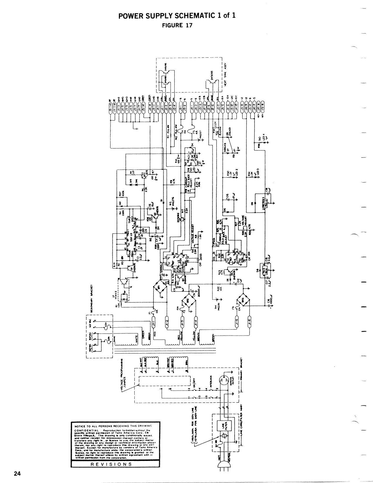
This page is a drawing, shown as the original scan.
FILTER BOARD
TAITO ITEM _|PART NO. DESCRIPTION QUANITY
| 1 | [12-10001-471 _ | CAP, 470PF= 10% AXIAL LEAD | 36 |
2__]17-00001-001_| FERRITE BEAD ASSEMBLY 18
| 3 | [25-00002-014 [CONNECTOR 14P | 9 |
| 4 | [25-00002-005 _ [CONNECTOR SP | 2 |
| 5 | [63800068.001 | STAND OFF | 6 |
| 6 | |17-10001-001 _ [10 UH INDUCTOR | 5 |
SOT Cf) conn, 5 Pin & | ops t N 3 || = L je INDUCTORS
: 3 = | |e > = SU a US [——— ——FAAITE Beads =e C5 i} i SsbB S > ty i S
SSF)
oly COT. C0 conn 14P || copytapacitor Lo Say
aig
This page reads as a drawing: its text was drawn rather than typeset, and comes out in fragments. See the original scan.
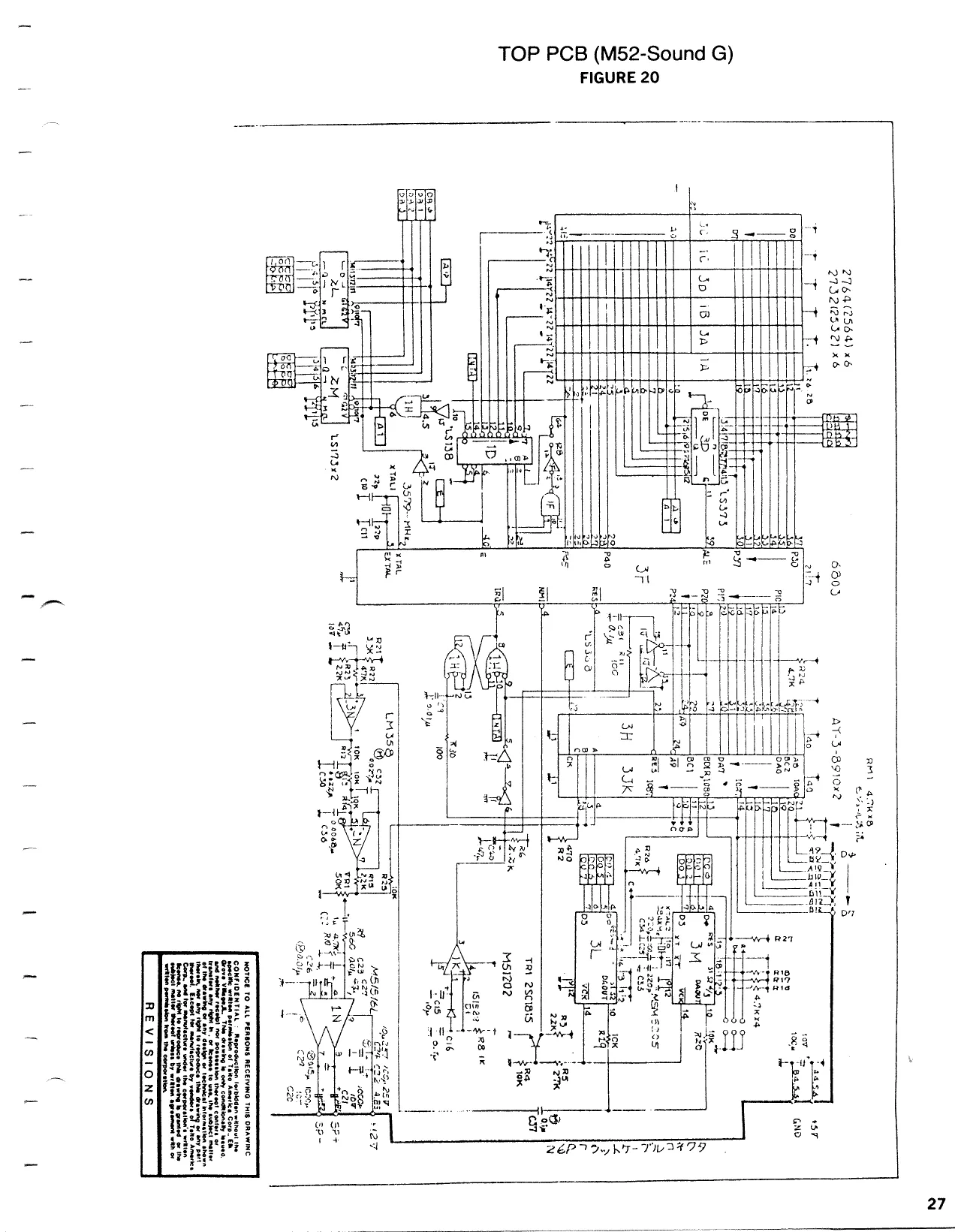
This page is a drawing, shown as the original scan.
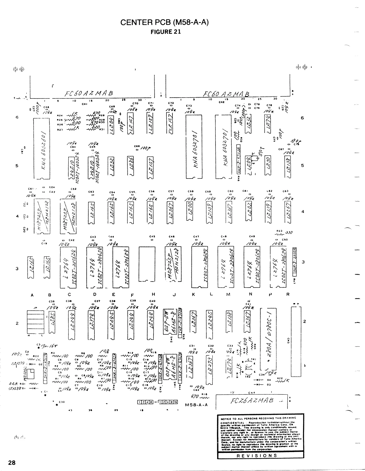
This page is a drawing, shown as the original scan.
CENTER PCB (M58-A-A) 1 of 4
CENTER PCB (M58-A-A) 2 of 4
CENTER PCB (M58-A-A) 3 of 4
CENTER PCB (M58-A-A) 4 of 4 FIGURE 22 _
cnt
als
| ioe | rE | Basi amA0 - |
| \ | 4 | ; |
ried a 2 wae “|
| 5 | = | Tn] 6F | . | _ |
32 :
CN2 a
id, 2
| nea | ; | t—— | |
| é | T | 1 | is |
im a i
| ia | ro | —+—F |
im r 1a!gH
| : | i | | |
1 Fi . | a 15 LP >
AES
1c
Vibe 32 1
ea
HE4E, CNT
284) 2.
3] le er m9] 28]7 ~ i eT a i 2souT
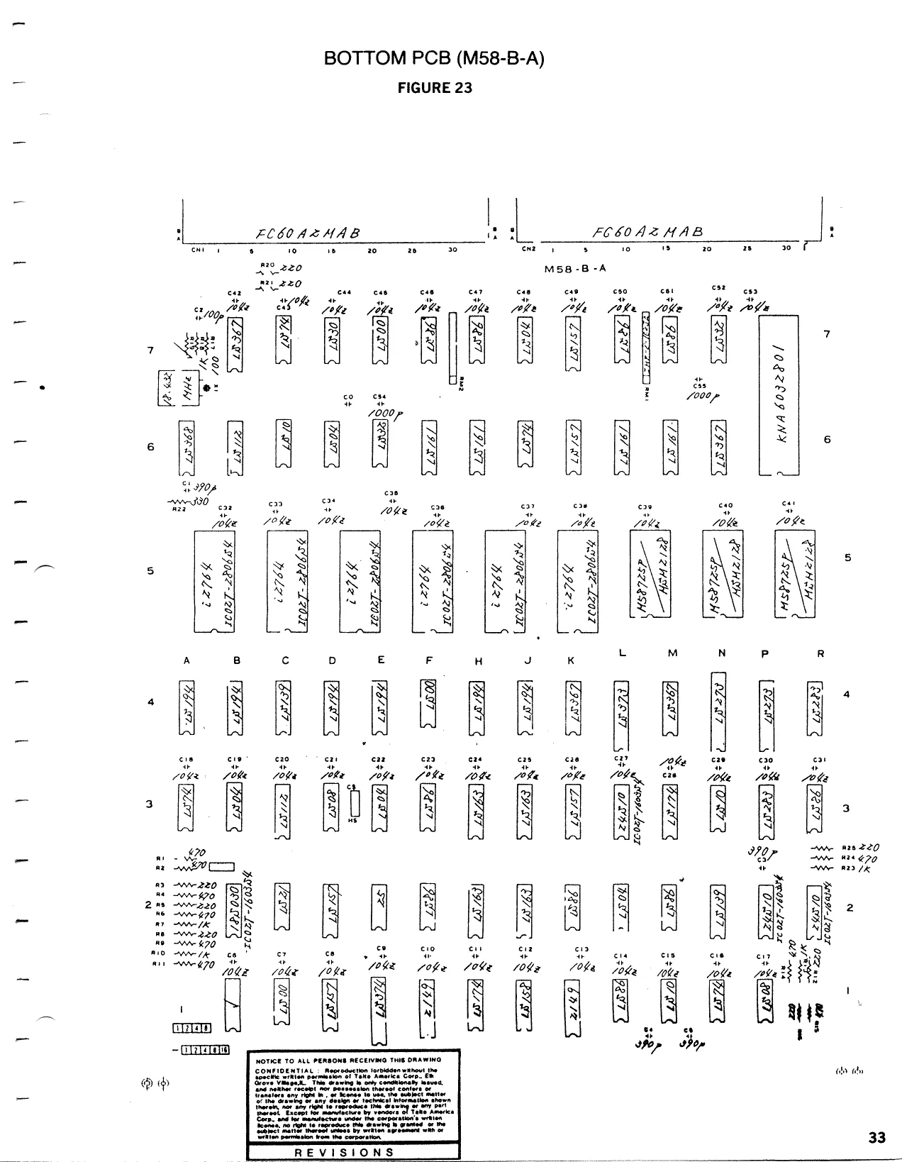
This page is a drawing, shown as the original scan.
BOTTOM PCB (M58-B-A) 1 of 5
LL ue Ll » Ll om ° 1 2
REVISIONS
BOTTOM PCB (M58-B-A) 2 of 5
von
iv
1009 g on mene O-ne xvod
BOTTOM PCB (M58-B-A) 3 of 5
oe eB ow ee ba © =RPORS ue oF 3
i \. Ww
o 8
ep |
Bho ak 3 i
WEB ~ wh.
ae
ee
TONGE To ALL PERSONS RECETVMO Tris ORAWING
SNOISIA3Y BOTTOM PCB (M58-B-A) 4 of 5
cnt e
BLUE
mt vs 26a) Gazz
BOTTOM PCB (M58-B-A) 5 of 5
WIRING DIAGRAM
PRIMARY _BRACKET
[1] 120 vac To secompary — SSS [2] BRACKET ON POWER SUPPLY 8 ° 20 = Jo {loo Yizo vac c
VIDEO RED
COMPOSITE NEG syNc| 2o;™4T
vo1o + [ze }ORe AUDIO—| 25} je SPEAKEI lors puK tol enol 1 Ete pi yeovac com sm cerr[sefem a samc | RED RED COIN sw. RIGHT|I9 .
service sw. [spel LEFT COIN cwTR| 7 [ORM RIGHT COIN cNTR[ ig fOLU
ory +12 [er
PC bUARD +5 [pofRe? +5 [aoe np [a3 fete
POWER SUPPLY PCB 08-00007-001
| eno aa | BLK] nig | BLK | | |
| JOYSTICK LEFT] 9 eRN | BRN | 3 [ORM | |
| soystick Down [36 |E2 | RED| ig | [RED |
sorsTick uP 35 [98S ORG lg, seen i hei ECTIONS —_
| JOYSTICK RIGHT]! fern | YEU Rige—e | feb | connec |
pe rey . . rorwano eass|ar WARD PA : thre |
FILTER BOARD 08-O0014!-O001 —L 7
| | wear SINK ASSY TYPICAL 4 PLACES han Bain | ™ OUT ont zs iaiaad TYPICAL 18 PLACES
WARRANTY
TAITO AMERICA CORPORATION warrants that its printed circuit boards and parts are free from defects in material and workmanship under nomal use and service for a period of ninety (90) days from the date of shipment. Seller warrants that its monitors are free from defects in material and workmanship under normal use for a period of thirty (30) days from the date of shipment. The factory also warrants all socketed parts for a period of ninety (90) days when furnished with the game serial number. If the above products fail to conform to this Warranty Taito America Corporation has the option to repair, replace, or credit the Buyer's account. The Buyer must notify Taito America Corporation in writing upon finding the defective product. Buyer must also return the defective product prepaid to Taito America Corporation's factory located in Elk Grove Village, Illinois. If Taito America Corporation determines upon examining the returned product that damage was caused by accident, misuse, neglect, modification, or improper repair or testing, this Warranty will be void. Inno event will Taito America Corporation be held for loss of profits to Buyer.
TAITO AMERICA CORPORATION 1256 Estes Avenue, Elk Grove Village, IL 60007 Telephone (312) 981-1000 Telex 25-3290