Quantum TM-221 1st Printing
Quantum (rev 2) (General Computer Corporation (Atari license), 1982) · Technical Manual · 80 pages · 49 sections · original scan
TM-221 1st printing
Operation, Maintenance,
and Service Manual
Complete with Schematics and Illustrated Parts Lists
If reading through this manual does not lead to solving a certain maintenance problem, call TELEHELP® at the Atari Customer Service office in your geographical area, as shown below.
WEST and CENTRAL U.S.A. Parts and Service
Alar, Inc California Customer Service Office 1105 N. Fair Oaks Avenue P.O. Box 427, Sunnyvale. CA 94086 Telex 17-1103 (Monday-Friday, 7°30-4:00 pm Pacific Time) eg From California, Alaska, or Hawaii oO @@ (408) 745-2900 em Service from anywhere in the area shown in white Oo @@ toll-free (800) 538-1611
EAST USA. Service only
Atari, Inc New Jersey Customer Service Office 12A World's Fair Drive, Somerset, NJ 08873 Telex 37-9347 (Monday-Friday, 7:30-4:00 pm Eastern time) ame =From New Jersey 2° (201) 469-5993 = From anywhere else in this area © toll-free (800) 526-3849
EUROPE _
Parts and Service
Atari Ireland Limited European Customer Service Office Tipperary Town, Ireland Telex 28165 TIPPERARY TOWN, (Monday-Friday, 9:00-6:00 pm GMT) IRELAND
J 06252155
Operation, Maintenance, and Service Manual
Complete with Schematics and Illustrated Parts Lists
Quantum
© 1982 by Atari, Inc. All rights reserved.
No part of this publication may be reproduced by any mechanical, photographic, or electronic process, or in the form of a phonographic recording, nor may it be stored in a retrieval system, transmitted, or otherwise copied for public or private use, without permission from the publisher. The game play, all graphic designs, this technical manual, its accompanying schematic diagrams, and the display manual are protected by the U.S. Copyright Act of 1976. This Act provides for increased penalties for violating federal copyright laws. Courts can impound infringing articles while legal action is pending. If infringers are convicted, courts can order destruction of the infringing articles. In addition, the Act provides for payment of statutory damages of up to $50,000 in certain cases. Infringers may also have to pay costs and attorneys’ fees, fines up to $25,000, and face an imprisonment of up to one year. Atari will aggressively enforce its copyrights against any infringers. We will use ail legal means to immediately halt any manufacture, distribution, or operation of a copy of video games made by us. Anyone who purchases such copies risks forfeiting such a game.
Published by: ATARI, INC. 790 Sycamore Drive P.O. Box 906 Milpitas, California 95035
Lithographed in the U.S.A. 12L
Quantum
Notice Regarding Non-ATARI Parts
Use of non-ATARI parts or modifications of your ATARI® game circuitry may adversely affect the safety of your game, and injure you or your players.
You may void the game warranty (printed on the inside back cover of this manual) if you do any of the following:
® substitute non-ATARI parts in the game @ modify or alter any circuits in the game by using kits or parts not supplied by Atari.
to licensed communications services is not permitted by the Federal Communications Commission (FCC). \f you suspect interference from an ATARI® game at your location, check the following: @ all green ground wires in the game are properly connected as shown in the the game wiring diagram @ the power cord is properly plugged into a grounded 3-wire outlet @ the game PCB is properly installed within the Electromagnetic Interference (EMI) cage @ the EMI Shield PCB is properly installed and in series with the game PCB harness. Refer to Figure 4-10 to make sure that the game PCB and the Shield PCB are correctly installed. If you are still unable to solve the interference problem, please contact ATARI Customer Service. See the inside front cover for service in your area.
iii
Quantum
Table of Contents
1 Set-Up Procedures A. New Features 1-3 B. Inspecting theGame .. 1-3 C. Space and Power Requirements 1-3
- Installation Requirements . 1-3
- Selecting the Voltage Plug... 1-3 D. Switch Locations ....... 1-4
- Power On/Off Switch 1-4
- Utility Panel Switches . 1-4
- Option Switches ....... 1-4 E. Setting the Option Switches . 15 F. Game Play 16
- Attract Mode 16
- Select Mode 1-6
- Play Mode.... 16
- High-Score Mode . ceeee 17
- Hints forGame Play ......... 0.00. c cee cece eee 1-7
2 Self-Test Procedure A. Comments on Troubleshooting .............. 0. cece ee eee eee 22 B. Performing the Self-Test ... 2-2
3 Maintenance and Repair A. Replacing the Fluorescent Tube ...............00 0c cece eee ee 33 B. Replacing the Speakers a OS C. Video Displays and Display Printed-Circui Boards ‘ 34 D. Control Panel 3-8 E. Midi Trak-Ball™ - 3-10 F. Game and Regulator/Audio || Printed-Circuit Boards .. 312 G. PowerSupply Fuses ......... 0... cece cece eee teen eee eee 3-14
4 Illustrated Parts Lists A. Cabinet-Mounted Assemblies ............ 00.0 c eee e eee neces 42 B. Fluorescent Tube and Speaker Assembly 44 C. Video Display Assemblies 46 D. Control Panel Assembly . . -. 49 E. Midi Trak-Ball™ Assembly 2. 410 F. Utility Panel Assembly ... -. 412 G. Coin Door Assemblies . 2 413 H. Printed-Circuit Boards ...... -. 420 |. Color X-¥Y Power Supply Assembly... ...... «. 435
Glossary of TermS ............0....0.c ccc cece eee ee ees GL
List of Illustrations
Figure 1-1 Figure 1-2 Figure 3-1 Figure 3-2
Figure 3-3 Figure 3-4 Figure 3-5 Figure 36
Figure 3-7 Figure 3-8
Figure 4-1 Figure 4-2 Figure 4-3 Figure 4-4 Figure 45 Figure 4-6 Figure 4-7 Figure 4-8 Figure 4.9 Figure 4-10 Figure 4-11 Figure 4-12 Figure 4-13 Figure 4-14 Game Overview. ....... 2.6.6 c cece eee teen eee 1-2 Switch Locations ....... 1-4 Fluorescent Tube and Speaker . .. 32 Amplifone Video Display ........... 00.0. e cece eee eee 3-4 Wells-Gardner Video Display ..... 2.0.6.0. e cee e eee eee eee 36 Opening the Control Panel a 38 Control Panel ......... -. 39 Midi Trak-Ball™ 0.2... cee cece cece eee teen eens 3410
Game and Regulator/Audio I! Printed-Circuit Boards ......... 3-12 Power Supply FuseS .......... 0. cece cee cect eee e ee eee 3-14
Ilustrated Parts Lists
Cabinet-Mounted Assemblies. ............ 00000 e cece ee ees 42 Fluorescent Tube and Speaker Assembly . . 44 Amplifone Video Display Assembly .... 46 Wells-Gardner Video Display Assembly . 48 Control Panel Assembly ......... i 49 Midi Trak-Ball™ Assembly . Utility Panel Assembly... tee 412 Vertically Mounted Coin Door Assembly . 413 American-Made Coin Door Assembly .......... 4-16 EMI Cage Assembly and PCB Mounting Hardware EMI Shield PCB Assembly..........-..--...5 Quantum Game Printed-Circuit Board Assembly . Regulator/Audio II Printed-Circuit Board Assembly “ Color X-Y Power Supply Assembly ............-.0.000 0 eee 435
List of Tables
Table 1-1 Table 1-2 Switch Settings for Price Options Quantum Scoring Quantum
Quantum
vi
NOTICE
This equipment generates, uses, and can radiate radio frequency energy and if not installed and used in accordance with the instruction manual, may cause interference to radio communications. It has been tested and found to comply with the limits for a Class A computing device pursuant to Subpart J of Part 15 of FCC Rules, which are designed to provide reasonable protection against such interference when operated in a commercial environment. Operation of this equipment in a residential area is likely to cause interference in which case the user, at his own expense, will be required to take whatever measures may be required to correct the interference.
Set-Up Procedures
How to Use this Manual
This manual, written for game operators and service technicians, describes the Quantum game. The manual contains information about the Upright cabinet. Chapter 1 describes new features, game setup, settings of option switches, and game play. Chapter 2 contains self-test procedures. Chapter 3 has maintenance and repair information. Chapter 4 contains illustrated parts lists. Figures 1-1 and 4-1 illustrate the game cabinet. Italicized lettering on these figures refers you to other places in the manual for information about specific cabinet parts. In addition, schematic diagrams of the game circuitry are included with this manual.
Chapter
Set-Up Procedures Quantum
FLUORESCENT TUBE & SPEAKER , GAME IDENTIFICATION LABEL « See Figures 3-1 & 4-2
ACCESS PANEL
VIDEO DISPLAY * See Figures 32 & 43
EMI CAGE See Figures 3-7 & 4-10 GAME PCB + See Figures 3-7 & 4-12
CONTROL PANEL See Figures 3-5 & 4-5
REGULATOR/AUDIO II PCB x MIDI TRAK-BALL™ See Figures 3-7 & 4-13 See Figures 3-6 & 4-6
FRONT PANEL GRAPHICS D is COIN DOOR 4 See Figures 4-8 & 4-9
POWER SUPPLY « POWER ON/OFF SWITCH See Figures 3-8 & 4-14 UTILITY PANEL See Figure 4-7
Your game is equipped with either a Wells-Gardner or an Amplifone 1%inch video display. Do not plug in the game until it has been inspected. This game should only be connected to a grounded 3-wire outlet. If you have only a 2-wire outlet, we recommend you hire a licensed electrician to install a grounded outlet. Players may receive an electrical shock if this game is not properly grounded! If your game has an Amplifone display, serial numbers are located on the video display, High-Voltage PCB, and Deflection PCB, in addition to the locations shown here.
Item with a serial number label
Figure 1-1 Game Overview
Quantum
A. New Features
The Quantum game has three new features. Even if you are familiar with ATARI® games, you should
- Front Panel Graphics. Graphics are added to the front panel to attract more players. ¢ Electromagnetic Interference (EMI) Cage. The game printed-circuit board (PCB) is mounted inside this cage. The EMI cage reduces interference from the game to television and radio receivers. New features and all other major parts of the game are illustrated in Figure 1-1. Throughout this manual, wherever one of these new features is mentioned,
you will see this symbol: ASS
B. Inspecting the Game
Please inspect your game carefully to ensure that it was delivered to you in good condition.
- Examine the exterior of the game cabinet for dents, chips, or broken parts.
- Remove the screws from the rear access panel. Unlock and open this panel and the coin door; inspect the interior of the game as follows: a. Ensure that all plug-in connectors (on the game harnesses) are firmly plugged in. Replug any connectors found unplugged. Do not force connectors together. The connectors are keyed so they only fit in the proper orientation. A reversed edge connector may damage a PCB and will void your warranty. b. Ensure that all plug-in integrated circuits on the PCB are firmly plugged into their sockets. c. Remove the tie-wrap that secures the coiled power cord inside the cabinet. Inspect the power cord for any cuts or dents in the insulation. Repair or replace it as required. Set-Up Procedures
Place the square black plastic strain-reliet plate in the wood slot at the bottom of the rear panel opening. d. Note the game serial number. It is printed on a label on the back of the cabinet. Verify that the same serial number is also on the game PCB, Regulator/Audio || PCB, power supply, and video display. See Figure 1-1 for locations of the serial-numbered components. Please mention this serial number whenever you Call your distributor for service. e. Inspect major subassemblies, such as the power supply, control panel, and video display. Make sure they are mounted securely, and that the green ground wires are connected.
C. Space and Power Requirements
- Installation Requirements
Power 250 W Temperature 0° to +38°C (+32° to + 100°F) Humidity Not over 95% relative Space Required 64 x 80 cm (25% x 31% in.) Game Height 184 cm (72% in.)
- Selecting the Voltage Plug The power supply used in this game operates on the line voltage of almost any country in the world. The power supply comes with either one, two, or three separate voltage-selection plugs. Plug voltages and wire colors are 100 VAC (violet wire color), 120 VAC (yellow wire color), 220 VAC (blue wire color), and 240 VAC (brown wire color). Before plugging in your game, check your line voltage. Next, check the wire color on the voltageselection plug that is plugged into the game’s power supply. Make sure the voltage-selection plug is correct for the voltage of your location (see Figure 4-14). Now plug the game into a grounded 3-wire outlet.
1-3
Set-Up Procedures
D. Switch Locations
- Power On/Off Switch
The power on/off switch is located on the back of the cabinet on the lower left side (see Figure 1-2).
- Utility Panel Switches The volume control, self-test switch, coin counter(s), and auxiliary coin switch are on the utility panel. The utility panel is located inside the upper coin door (see Figure 1-2.) The volume control adjusts the level of sound produced by the game. The
UTILITY PANEL See Figure 4-7
COIN COUNTER eric AUXILIARY COIN SWITCH VOLUME CONTROL (To increase, turn clockwise) Quantum
self-test switch is used to enter and exit the Self- Test Mode. The coin counter(s) records the number of coins entered into the game. The auxiliary coin switch is used to credit the game without activating a coin counter.
- Option Switches
Game price option switches are located on the game PCB at location 4C/D (see Figure 1-2).
OPTION SWITCH AT 4C/D POWER ON/OFF (Game price) SWITCH OPTION SWITCH AT 4B (Not used)
Figure 1-2 Switch Locations
1-4
Quantum
E. Setting the Option Switches
Please see CO-221-07, supplement to TM-221, for information on this section. Set-Up Procedures
Set-Up Procedures
F. Game Play
Quantum is a one- or two-player game with a color X-Y video display. The game action takes place in a subatomic world. The player tries to capture deadly atomic particles without being destroyed by them. To capture particles, the player uses the Midi Trak- Ball™ to control a comet that sparkles. When the player rotates the Midi Trak-Ball™, the comet leaves a tail (or line) behind it. The player must draw a complete circle around the deadly particle to destroy it. Quantum has five possible modes of operation: Attract, Select, Play, High-Score, and Self-Test. Self- Test is a special mode for checking the game switches and computer functions. You may enter the Self-Test Mode from any other mode.
- Attract Mode
The Attract Mode begins when you turn the power on/off switch on, or after a Play, High-Score, or Self- Test Mode. The Attract Mode consists of a series of five screens. In the first screen the word QUANTUM appears in the center of the screen and increases in size. Credits (if any) appear at the bottom of the screen. The second screen instructs the player how to play the game. The third screen gives the player a chance to actually play the game without inserting a coin! The screen displays TRY CAPTURING THIS ATOM and MOVE THE TRAKBALL. The fourth screen displays the day's top score and the high-score table. The fifth screen displays the word QUANTUM, the highest score, and previous game score(s) at the top of the screen. A simulated game is in the center of the screen. If the game has no credits, the words /N- SERT COINS appear. If the game has credit(s), a message instructs a player to press the appropriate start button. The Atari copyright message, number of lives, credits, and level of game play appear at the bottom of the screen. When enough credit(s) is inserted for a 1- or 2-player game, the appropriate 1- or 2-player LED flashes. When the player presses the flashing LED start button, the Select Mode begins. Quantum
- Select Mode
This mode begins when an LED start button is pressed. The player has 30 seconds to select the starting level. He can start a game at an advanced level of play and receive bonus points for starting play at that level. The starting levels appear at the bottom of the screen. The player chooses the starting level by circling it, using the Midi Trak-Ball™.
- Play Mode The Play Mode begins when the Select Mode ends and ends when the player's last comet is destroyed. The player’s score(s) and highest score are displayed at the top of the screen. The number of remaining comets and the level of play are displayed at the bottom of the screen. In the first level of play, various particles appear on the screen. When a player captures a particle, it explodes and its point value appears on the screen. Some particles, such as electrons, change into positrons and are worth extra points if captured. If a player captures more than one particle at a time, he earns double points. The first level of play ends when the player captures all of the nuclei. Game play becomes more difficult as the game progresses. Particles are closer together and move faster. More particles appear on the screen at one time. Nuclei may appear tied together by a rope-like bond. Players may capture one or both nuclei in a bond. The player’s comet may cross over the bond until it changes to red. If the comet tries to cross over a red bond, the comet is destroyed. During a later wave, pulsars appear. The pulsar travels toward the comet and pulses its arms in and out as it moves. The player’s comet is destroyed if it comes in contact with any part of the pulsar. Splitters also appear in a later wave. A splitter multiplies if it is not destroyed. The comet is destroyed when it hits a particle or the red bond between nuclei. The game ends when all of the player's comets are destroyed. Table 1-2 lists Quantum particles and their point values.
Quantum
- High-Score Mode The High-Score Mode begins when a player has earned one of the eleven highest scores. If a player has earned the highest score, a special option allows him to sign his name using the Midi Trak-Ball™, as well as enter his initials into the highscore table. Characters of the alphabet appear on the screen. The player rotates the Midi Trak-Ball™ to locate his initial. He circles his initials and they appear in the center of the screen. Then the initials and score are transfered into the high-score table. To reset the high-score table, refer to Chapter 2. ‘Set-Up Procedures.
Hints for Game Play
Circle two or more objects for double points. Capture all the nuciei to advance to the next wave. Move the Midi Trak-Ball™ quickly to keep the comet's tail from disintegrating and to produce a longer tail. Avoid deadly red bonds between nuclei.
Table 1-2 Quantum Scoring
Particle Description Points
| Electron | e | Rotates slowly around Nucleus. | 20 |
| Triphon | & | Moves slowly and flashes colors. Leaves Tryd in its trail. | 100 |
| Splitter | vy, | Travels in a random pattern. Flashes color, splits into 3, and splits | 100 |
I~ into 3 again.
| proton | _Z\._ | Enters from the edge of the screen, spins across the screen, and | 200 |
exits from the other side.
| Positron | + | Made of stray electrons after a nucleus explodes. Moves to the | 200 |
edge of the screen rapidly.
| Tryd | © | Slowly shrinks away and disappears. | 300 |
| Nucteus | — @_—_— | Moves stowly and bounces off screen edge. Cuts off the end of a | 300 |
comet's tail when the nucleus crosses over tail.
| Pulsar | ry’ | Pulses as it travels toward comet. | 400 |
1-7
This page carries no recoverable text. It is a drawing or a photograph. See the original scan.
Self-Test Procedure
This game will test itself and provide data to show that the game’s circuitry and controls are operating properly. The data is provided on the video display and speaker. No additional equipment is necessary. We suggest you perform the self-test procedure when you first set up the game, any time you collect money from the game, when you change game options, or when you suspect game failure.
Chapter
Self-Test Procedure Quantum
A. Comments on Troubleshooting
When troubleshooting, first determine the symptom(s) of the failure. After determining the symptom, look over the wiring diagram and determine what assemblies could cause the failure. Could it be caused by the power supply, Regulator/Audio II printed-circuit board (PCB), or the video display? The next step is to check all harness wires and connectors to the suspected assembly. If you do not find a harness or connector problem, substitute an assembly known to be good for the suspected failing assembly. If the game functions properly, you have successfully isolated the failure. If it doesn’t, repeat the procedure with another assembly. When you have isolated the failing assembly, you must troubleshoot that assembly and make the necessary repairs. If the video display fails, we Suggest that a qualified video-display technician handle the troubleshooting and repair. Be sure to refer to The Book—A Guide to Electronic Game Operation and Servicing, published by Atari, Inc., whenever you need help with the techniques, tools, and terminology associated with coinoperated electronic games. To effectively troubleshoot a game PCB, learn as much as you can about the PCB. The diagrams in the Schematic Package (included with the game) show the functions of the circuitry. Again, while troubleshooting a PCB, first determine the symptom of the failure, then locate the suspected area on the schematic diagram.
B. Performing the Self-Test
Please see CO-221-01, supplement to TM-221, for information on this section.
2-2
Please see CO-227-01, supplement to TM-221, for information on this section.
Please see CO-221-01, supplement to TM-221, for information on this section.
Please see CO-221-01, supplement to TM-221, for information on this section.
Please see CO-227-01, supplement to TM-221, for information on this section.
Maintenance and Repair
This chapter details maintenance and repair information. Step-by step procedures show you how to disassemble, repair, or replace major assemblies in the game. For parts information, refer to Chapter 4.
Chapter
Maintenance and Repair Quantum
LOWER RETAINER
ATTRACTION PANEL
Figure 3-1 Fluorescent Tube and Speaker
3-2
Quantum
A. Replacing the Fluorescent Tube
Before removing or repairing the fluorescent tube or speaker, turn the game off. If you drop a fluorescent tube and it breaks, it will implode! Shattered glass can fly six feet or more from the implosion. Use care when replacing any fluorescent tube.
1A. Remove the three sets of hardware that secure the upper attraction-panel retainer to the cabinet (see Figure 3-1). Loosen the three sets of hardware that secure the lower retainer to the cabinet. 2A. Lift the attraction panel out of its lower retainer. 3A. Remove the cardboard locking tab at each end of the tube. Slightly rotate the tube up or down and carefully remove it from the tube holders. 4A. Replace with a new tube. Do not snap the tube in vigorously—you may break it, causing an implosion! Replace the locking tabs. 5A. Check that the green ground wire is securely attached to the large metal bracket and the ballast transformer on the board. If the tube is not grounded, it may not start. Reassemble in reverse order. Maintenance and Repair
B. Replacing the Speakers
1B .Upper speaker (located above the videe display). Follow steps 1A and 2A for replacing the fluorescent tube (see Figure 3-1). Remove the hardware that secures the tube and speaker board to the cabinet. 2B.Slide the tube and speaker board partially out of the cabinet. Turn it sideways to unplug the 5-pin harness connector. Remove the board from the cabinet. 3B.Unplug the two plug-in connectors on the speaker. (Note that the white wire (+) connects on the side marked with a painted dot.) Remove the hardware that attaches the speaker to the board. Replace the speaker and reinstall the tube and speaker board in reverse order. 4B.Lower speaker (located below the control panel—not shown). Open the rear access panel. Unplug the two plug-in connectors on the speaker. (Note that the white wire (+) connects on the side marked with a painted dot.) Remove the hardware that attaches the speaker to the cabinet. Replace the speaker and reassemble in reverse order.
3-3
Maintenance and Repair
C. Video Displays and Display Printed-Circuit Boards
SHIELD b RETAINER Quantum
2-PIN ANODE
CONNECTOR (3) CONNECTOR
SPIN
@) CONNECTOR
DEGAUSSING COIL 7
2-PIN CONNECTOR
Figure 3-2A Amplifone Video Display CRT Removal
CRT
ANODE
CONNECTOR (2)
SOCKET (3)
2-PIN CONNECTOR ©
RETAINER
9-PIN HARNESS (©) connector (4)
Figure 3-2B Amplifone Video Displzy
High-Voltage PCB Removal
RETAINER
- SCREW
- DEFLECTION PcB CONNECTOR
Figure 3-2C Amplifone Video Display Deflection PCB Removal
Quantum
Your game has either an Amplifone or a Wells- Gardner 19-Inch Color X-Y cathode ray tube (CRT). Use the following procedures to remove and reinstall your CRT. Refer to Figures 4-3 and 4-4 for parts information. The Amplifone Color X-Y Display consists of the following three assemblies: ¢ 19-inch Amplifone cathode-ray tube (CRT)
- Deflection printed-circuit board (PCB) calibrated to match the CRT ¢ High-Voltage PCB (To adjust FOCUS and BRIGHTNESS, refer to TM-194, the Amplifone 19-Inch Color X-Y Display manual.)
Removing the Amplifone CRT:
- Open the rear access panel. Disconnect the 15-pin harness connector wired to the Deflection PCB (see Figure 3-2C).
- Discharge the high-voltage from the CRT (refer to the preceding WARNING for this procedure).
- Carefully disconnect the high-voltage anode connector from the CRT (see Figure 3-2A). Maintenance and Repair
- Unplug the socket from the rear of the CRT.
- Unplug the degaussing coil 2-pin connector from the Deflection PCB.
- Unplug the 5-pin connector from the Deflection PCB.
- Unplug the 2-pin connector to the DAG spring that goes across the back of the CRT.
- From the front of the game, open the control panel (see Figure 3-4).
- Securely grasp the meta! retainer that supports the display shield (see Figure 3-2A). Remove the retainer and shield by sliding them down and out of the cabinet.
- Remove the cardboard bezel.
- Remove the four sets of hardware that secure the CRT to the wood frame. 12, Carefully remove the CRT out through the front of the cabinet. Place it on a soft mat in a protected location.
- To install an Amplifone CRT, reverse the order of this procedure.
Removing the Amplifone High-Voltage PCB:
- Discharge the high-voltage from the CRT (refer to the preceding WARNING for this procedure).
- Carefully disconnect the high-voltage anode connector from the CRT (see Figure 3-2B).
- Unplug the socket from the rear of the CRT.
- Unplug 9-pin connector P109 from the Deflection PCB.
- Unplug the 2-pin connector from the DAG spring.
- Remove the hardware that secures the High- Voltage PCB and two harnesses to the game cabinet.
- Slide the High-Voltage PCB from the wood retainers.
- To install a High-Voltage PCB, reverse the order of this procedure.
Removing the Amplifone Deflection PCB:
- Unplug the four connectors from the Deflection PCB (see Figure 3-2C).
- Remove the hardware that secures the Deflection PCB to the game cabinet.
- Slide the Deflection PCB from the wood retainers.
- To install the Deflection PCB, reverse the order of this procedure.
Maintenance and Repair
Wells-Gardner Video Display:
Removing the Wells-Gardner Color X-Y Display:
- Open the rear access panel and unplug the interconnect harness from the main harness. Remove the hardware that secures the display chassis to the metal bracket (see Figure 3-3).
- Open the control panel (see Figure 3-4).
- Securely grasp the metal retainer that supports the display shield. Remove the retainer and shield by sliding them out and down from the cabinet.
- Remove the cardboard bezel.
- Remove the four sets of hardware that secure the display chassis to the wood frame.
- Carefully remove the video display through the front of the cabinet. Place it on a soft mat in a protected location.
- To install the display, reverse the order of this procedure.
SHIELD
RETAINER \o ‘WOOD FRAME
BRACKET INTERCONNECT HARNESS
Figure 3-3 Wells-Gardner Video Display
3-6
This page carries no recoverable text. It is a drawing or a photograph. See the original scan.
Maintenance and Repair Quantum
D. Control Panel
Opening the Control Panel: 3. Lift the control panel at the top edge and tilt it toward you.
- Unlock and open the coin door (see Figure 3-4). 4. Make sure the foam tape on the lower edge of
- Reach up through the opening to the sides of the display shield is in good condition. This tape the control panel and release the spring-drawn prevents liquids from entering the interior of the latches. cabinet.
COIN DOOR
Figure 3-4 Opening the Control Panel
3-8
Quantum
Before you remove or repair any switch on the control panel, turn the game off.
Testing the LED Start Switch*: These switches have a very low failure rate. If you suspect switch failure, test it using the following directions:
- Disconnect the wires from the switch.
- Zero an ohmmeter. Set the ohmmeter switch range at x10. Attach the leads of the onmmeter to the normally open and common contacts (refer to Figure 3-5).
- Check the contacts for closed and open continuity. Close the switch and the ohmmeter
- Not illustrated Maintenance and Repair
should read zero. Release the switch and the ohmmeter should read infinity.
- If the contacts do not operate sharply or always remain closed or open, replace the switch.
Replacing the LED Start Switch:
- Disconnect the wires from the switch.
- Turn the switch counterclockwise while holding the black cone-shaped switch bezel on the outside of the control panel (See Figure 3-5).
- Install a new switch using the reverse procedure.
- Reconnect the wires as shown in Figure 3-5.
VERTICAL-MOTION PCB: BLACK, RED, YELLOW, and GREEN WIRES
MIDI TRAK-BALL™ ASSY.
HORIZONTAL-MOTION PCB: BLUE, VIOLET, RED, and BLACK WIRES,
HARNESS“
2-PLAYER LED START SWITCH WHITE al | ORANGE RED(+) ie | (Normally open contact)
BLACK (Common contact) ! WARNING !
Players may receive an electrical shock if this control panel is not properly grounded! After servicing any parts on the panel, check that the ground wire is firmly attached to the metal tab on the inside of the control panel. Only then should you lock up the game.
is “> suite BEZEL
1-PLAYER LED START SWITCH
Garay 71 BROWN RED(+) 1G (Normally open &y mt contact) BLACK (Common contact)
Figure 3-5 Control Panel
Maintenance and Repair
E, Midi Trak-Ball™ bored inctructions. Disessemble
@ my
@ eEncopine WHEEL © Fiat wasHER SPLIT-LOCK WASHER SCREW GN
@ LOWER FRAME Quantum
in the order indicated.
(Six places}
UPPER FRAME (2) LUBRICATE HERE
coupter pce (5) ” OPTICAL COUPLER
@ Rep CONNECTOR (Not shown)
Figure 3-6 Midi Trak-Ball™
Quantum
Before removing or repairing the Midi Trak-Ball™, turn the game off.
Lubricating the Midi Trak-Ball™ Assembly:
- Remove the entire Midi Trak-Bali™ assembly from the control panel (see Figure 3-5). Remove the six screws that secure the upper and lower frames together (see Figure 3-6).
- Lift off the upper frame.
- Lubricate each of the six ball bearings with two drops of a light-duty oil, such as 3-in-One oil. Lubricate the bearings approximately every three months or 6,000 credits (credits are counted on the coin counter).
Removing the Midi Trak-Ball™, Coupler PCB, and Encoding Wheel:
- Perform steps 1 and 2. Remove the Midi Trak- Ball™.
- Lift the Coupler PCB out of its slot. Carefully disconnect the red connector and remove the PCB. Maintenance and Repair
- Remove the screw, flat washer, and split-lock washer that secure the encoding wheel.
- Remove the encoding wheel. Reassemble and reinstall in reverse order.
Adjusting the Midi Trak-Ball™ control:
- When you tighten the encoding wheel, rotate the socket-head screw on the end of the roller shaft until a hole in the shaft is visible through the hole in the upper frame.
- Insert a %-inch diameter pin or screwdriver through the hole in the shaft.
- Tighten the socket-head screw with an Allen wrench.
SOCKET-HEAD SCREW HOLE IN UPPER FRAME
HOLE IN ROLLER SHAFT
Figure 3-6 Midi Trak-Ball’”, continued
an
Maintenance and Repair Quantum
F. Game and Regulator/Audio II
Printed-Circuit Boards
@) HARNESS CONNECTOR
—& SNAP-IN
a FASTENER
(a) EMI SHIELD PCB
See Figures 4-10 & 4-11 EMI CAGE
auwe (Gy REGULATOR!
- aupio lt pcB See Figure 4-13
QUANTUM GAME PCB (4)
See Figure 4-12 ® SPACER
(7f Connectors
SCREW
- EDGE CONNECTOR be housed in the EMI cage with the Shield PCB attached.
Figure 3-7 Game and Regulator/Audio || Printed-Circuit Boards
Quantum
Before you remove or repair any printedcircuit board, tum the game off.
Removing the Game Printed-Circuit Board:
- Open the rear access panel.
- The game printed-circuit board (PCB) is located inside the electromagnetic interference (EMI) cage (see Figure 3-7). Unplug the harness connector on the EMI Shield PCB.
- To remove the game PCB, pull the eight nylon snap-in fasteners on the EMI Shield PCB to the unlocked position.
- Carefully slide the Shield PCB and the attached game PCB straight out of the guide. Be careful not to twist the boards, as this may loosen connections or components. Replace or repair as required. Reinstall the game and Shield PCBs in reverse order.
Removing the EMI Shield PCB from the Game PCB:
- Remove the pan-head screws that connect the EMI Shield PCB to the spacers.
- Push the EMI Shield PCB off the game PCB by applying pressure with your thumbs to the edge connector. Maintenance and Repair
Removing the Regulator/Audio Printed-Circuit Board:
- Disconnect the five small harness connectors on this board (see Figure 3-7).
- Remove the hardware that secures the Regulator/Audio || PCB to the cabinet, and carefully remove the board from its retainers. Do not twist the board, as this may loosen connections or components. Replace or repair as required, and reinstall the PCB.
- Close and lock the rear access panel.
- Important: Perform the self-test after repairing or replacing a printed-circuit board.
Maintenance and Repair Quantum
G. Power Supply Fuses
FUSE AT F1 (7 A, 250 V)
FUSE AT F2 (4A, 250V)
FUSE AT F3 (20 A, 32 V)
FUSES AT F4-F6 (4A, 250 V)
Fuse cover not shown.
Figure 3-8 Power Supply Fuses
3414
Illustrated Parts Lists
This chapter provides information you need to order parts for your game. Common hardware (screws, nuts, washers, etc.) has been deleted from most of the parts lists. However, there is a parts list for the hardware needed to mount the game and Regulator/Audio Il PCBs to the cabinet. The PCB parts lists are arranged in alphabetical order by component. Each component subsection is arranged alphanumerically by reference designator. Other parts lists are arranged alphanumerically by Atari part number. In these parts lists, all A-prefix numbers come first. Following these are numbers in sequence evaluated up to the hyphen, namely 00through 99-, then 0005980- through approximately 201000-. When ordering parts, please give the part number, part name, number of this manual, and serial number of your game. This wil! aid in filling your order rapidly and correctly. We hope the results will be less downtime and more profit from your game. Atari Customer Service numbers are listed on the inside front cover of this manual.
Chapter
llustrated Parts Lists Quantum
A. Cabinet-Mounted ween soe pars let on folowing page Assemblies
A039518-01 037332-01 (Cabinet assy.) (Vent. grla) A038881-01
Fluorescent Tube and Speaker 178034024 See Figure 4-2 (T-Molding)
037419-02 (Access panel)
037308-01 (Speaker grille) 1 A200000-0' (Amplifone kit assy)
039521-01 AD (Display shield) EMI Cage See Figure 4-10
Video Display Game PCB See Figures 4-3 or 4-4 See Figure 4-10
EMI Shield PCB Mii Trak Ball™ See Figure 4-11 ee Figure 4- Regulator! Audio 1 PCB 037308-01 See Figure 4-13 (Speaker grille) ‘A038588-01 (Power harn. assy.) (Coin box Coin Door Assy. enclosure} See Figures 4-8 or 4-9
Power Supply See Figure 4-14
A037453-03, A037455-03, or A037784-03 (Power cord) Utility Panel Assy. 478048-001 A037470-01 See Figure 4-7 (Caster) (Power on/off L switch assy.) 009992-01 (On/off switch cover) ™ 78-3201 (Glide)
Figure 4-1 Cabinet-Mounted Assemblies A039519-01 A
Quantum Illustrated Parts Lists
Cabinet-Mounted Assemblies Parts List
Part No. Description A037453-03 Strain-Relief Power Cord (U.S. and Canada) A037455-03, Strain-Relief Power Cord (Australia and New Zealand) A037470-01 Power On/Off Switch Mounting Plate Assembly A037701-02 Electromagnetic Interference (EMI) Cage Assembly A037784-03 Strain-Relief Power Cord (United Kingdom, Ireland, Lebanon, Saudi Arabia, India, Hong Kong, Singapore, Egypt, Nigeria, Republic of South Africa, Zimbabwe) A038588-01 Power Harness Assembly A038881-01 Lock Assembly (for rear access panel) Acceptable substitute is part no. A038881-03 A039518-01 Cabinet Assembly (includes glides and PCB retainers, but not the rear access panel) A039551-01 Main Harness Assembly A039579-01 EMI Shield PCB Assembly A200000-01 Amplifone 19-Inch Color X-Y Display Kit Assembly Acceptable substitute is 19-inch Wells- Gardner Display part no. A038590-01.
The following five items are the technical information supplements to this game: C0-221-01 Supplement to TM-221 ‘SP-221 Quantum Schematic Package ST-221-01 Quantum Label with Self-Test Procedure and Option Switch Settings TM-194 Service Manual for 19-Inch Amplifone Color X-Y Display (use with part no. A200000-01) Acceptable substitute is TM-183, for use with part no. A038590-01 TM-221 Quantum Operation, Maintenance, and Service Manual 78-3201 Adjustable Glide 009992-01 On/Off Switch Cover 037308-01 Speaker Grille 03733201 Ventilation Grille 037419-02 Rear Access Panel (does not include lock) 038091-01 Molded Coin Box (not shown) 038870-01 Coin Box Enclosure 039521-01 Video Display Shield 178013-001 Spring Draw Latch (not shown) 178034-024 %-Inch Black Plastic T-Moiding 178048-001 2-Inch Rigid Caster
Illustrated Parts Lists Quantum
B. Fluorescent Tube and
Speaker Assembly
037309-01 148001-017 (Upper retainer) ; (Speaker)
179035-001 (Tube holder) 79-561816P (Wire nut) 99-1103 (Starter) 99.1009 038151-01 (Socket) (Jumper wire)
(Hamess)
70-304 (Tube)
142028-xxx (Transformer)
/ / 037469-01 (Bracket) 039525-01 (Attraction panel/graphics) ¢ panel/ grap! 03754001
(Ground wire) 037304-01 7 (Lower retainer},
78-6900404 (Tape) Z
Figure 4-2 Fluorescent Tube and Speaker Assembly A038161-01 & 02 A
Quantum Illustrated Parts Lists
Fluorescent Tube and Speaker Assembly Parts List
Part No. Description A037457-01 Tube and Speaker Harness Assembly A037540-01 Ground Wire with Ring Lug 70-304 18-Inch, 15-Watt, Cool White Fluorescent Tube 78-6900404 Vinyl Foam Single-Coated Adhesive Tape, %-Inch Wide x % Inch Thick (48 inches required) 79-561816P Spring-Connector Wire Nut for 16- to 18-Gauge Wires 99-11003 Fluorescent Tube Starter 99-11006 Fluorescent Tube Locking Tab (consists of two pieces) 99-11009 Starter Socket 037304-01 Lower Attraction Panel Retainer 037309-01 Upper Attraction Panel Retainer 037469-01 Steel Tube Bracket 038151-01 15-Inch Jumper Wire 039525-01 Attraction Panel with Graphics 142028-001 60 Hz, 118 V, Ballast Transformer (used on A038161-01 assembly) 142028-002 50 Hz, 118 V, Ballast Transformer (used on A038161-02 assembly) 148001-017 6 x 9-Inch Oval, 8 2, 6-Ounce, Shielded High-Fidelity Speaker 179035-001 2-Pin Fluorescent Tube holder
Illustrated Parts Lists Quantum
C. Video Display Assemblies
038184-01 (Static shield)
A201012-01 (High-voltage PCB)
034536-01 (Foam pad)
038184-01 (Static shield)
A201014-01 (Deflection PCB)
Figure 4-3 Amplifone Video Display Assembly A200000-01 B
Quantum
039521-01 (Shield) 039530-01 A201001-01 (Bezel) (Amplifone CRT) Illustrated Parts Lists
(Retainer)
Figure 4-3 Amplifone Video Display Assembly, continued A200000-01 B Parts List
Part No. Description A201001-01 49-Inch Amplifone Color X-Y CRT A201012-01 High-Voltage PCB A201014-01 Deflection PCB 034536-01 Foam Pad (used with Deflection and High Voltage PCBs) 038184-01 Static Shield 039521-01 Display Shield 039523-01 Display Shield Retainer 039530-01 Display Bezel
Illustrated Parts Lists Quantum
039521-01 039530-01 92-053 (Shield) (Bezel) {Wells-Gardner display)
039523-01 A038593-01 (Retainer) {interconnect assy.) SapseHot (Bracket)
Figure 4-4 Wells-Gardner Video Display Assembly A038590-01 A Parts List
Part No. Description A038593-01 Wells-Gardner Interconnect Harness Assembly 92-053 19-Inch Wells-Gardner Color X-Y Video Display 039521-01 Display Shield 039530-01 Display Bezel 039523-01 Display Shield Retainer 039531-01 Metal Support Bracket
Quantum
D. Control Panel Assembly
A038038-01 Midi Trak-Ball™ Assy. See Figure 4-6 lilustrated Parts Lists
Players may receive an electrical shock if this control panel is not properly grounded! After servicing any parts on the panel, make sure that the ground wire is firmly attached to the metal tab on the inside of the control panel.
036895-01 (Switch bezel)
62-039 (LED switches)
A039512-01 (Control panel with decal) 03951104 (Decal—not shown) A039513-01 (Control panel) A039552-01 (Harness)
Figure 4-5 Control Panel Assembly A039514-01 A Parts List
Part No. Description
A038038-01 Midi Trak-Ball™ Assembly A039512-01 Control Panel with Decal A039513-01 Control Panel A039552-01 Control Panel Harness Assembly 039511-04 Control Panel Decal (not shown) 62.039 SPDT Momentary Pushbutton Start Switch with Red Light-Emitting Diode 75-S41S #10-24 Self-Locking Nut 75-5148B #10-24 Black Carriage Bolt 036895-01 Black Molded Switch Bezel
Illustrated Parts Lists Quantum
E. Midi Trak-Ball™ Assembly
038039-01 176010-106 j (Screw) (Upper frame)
See Figure 3-6 for lubrication information.
038043-01 ; <a (Midi Trak-Ball) 035937-01 ome (Ball bearing) 038042.01 (idler shat) —_] 4 038041-01 (Roller shaft)
03593801 VERTICAL-MOTION PCB: & BLACK, RED, YELLOW, €Encoding wheel oT and GREEN WIRES 75.0148, (Flat washer) — iC 75-0448 Or Uw (Splitock washer) -
(Socket-head screw) A036096-01 (Harness assy)
139002001 (Optical coupler— hidden from view) HORIZONTAL-MOTION PCB: BLUE, VIOLET, RED, and BLACK WIRES
038040-01 (Lower frame)
A035220-02 (Coupler PCB assy.)
Figure 4-6 Midi-Trak-Ball™ Assembly A038038-01 B
4-10
Quantum \lustrated Parts Lists
Midi-Trak-Ball™ Assembly Parts List
Part No. Description A035220-02 Coupler PCB Assembly (includes Radial Optical Coupler) A036096-01 Harness Assembly 72-8406 #4-40 x %-Inch, Hex Socket-Head Steel Machine Screw 75-014S #4 Flat SAE-Standard, Zinc-Plated Steel Washer 75-044S #4 Split-Lock, Zinc-Plated Stee! Washer 034168-01 Label with Lubrication Instructions (not shown) 035937-01 Ball Bearing (6 per assembly) 035938-01 Etched Encoding Wheel 038039-01 Upper Black Plastic Frame 038040-01 Lower Black Plastic Frame 038041-01 Roller Shaft 038042-01 Idler Shaft 038043-01 Midi-Trak-Ball (3-inch diameter) 139002-001 Radial Optical Coupler (located on the Coupler PCB Assembly) 176010-106 #8 x %Inch Cross-Recessed, Pan-Head, Zinc-Plated Steel Screw 107013-001 3-In-One Oil lubricant
Illustrated Parts Lists Quantum
F. Utility Panel NOTE Only the Ireland-Built cabinet has two coin Assembly counters
‘A038004-01 (Harness) A002465-01 a (Coin counter)
038003-01 (Panel)
62-041 (Auxiliary coin switch)
19-9032 (Volume control)
(Self-test switch) 178070-001 (Volume control knob) Ss
Figure 4-7 Utility Panel Assembly A038002-01 & -02 F Parts List
Part No. Description
A002465-01 6 V Coin Counter A038004-01 Utility Panel Harness 19-9032 Volume Control 62-041 SPDT Momentary-Contact Pushbutton Auxiliary Coin Switch with Black Cap 69-001 DPOT Self-Test Switch 038003-01 Utility Panel 178070-001 Volume Control Knob
4-12
Quantum
G. Coin Door Assemblies
179047-001 (Lamp Base)
99-15056 (Screw for Bezel)
99-15025 (Coin Inlet)
99-15055
75-9148 (Hex Nut (Hex Nut) (Lock Wash.)
9015075 i (Sw. Adjuster) y 170000-001 (Lamp)
. 99-15026 i. ‘Coin Iniet)
99-15029 (Bracket)
(Switch) Itustrated Parts Lists
99-15023 (Base Plate)
99-15054 (Pivot for Lever)
99-15028 (Coin Return Box)
<— 99-15060 (Sw. Cover)
T21414S (Screw)
Figure 4-8 Vertically Mounted Coin Door Assembly 171034-xxx A
{Illustrated Parts Lists
99-10139 (Coin door) >|
99-10145 —>(9 aS (Cam) POR
gS %
72-JA1405B (Screw)
036091-01 {Coin box)
171034-001 — U.S. 25¢/25¢ Coin Door 171034-003 — Canadian 25¢/25¢ Coin Door 171034005 — U.K. 10 P/50 P Coin Door Quantum
99-10148 (Lock)
72-HA1404C (Screw) 99-10142
99-10118 (Button)
99-10115 (Spring)
99-10141 (Coin return cover)
99-10117 (Coin return door)
99-10144 [~—(Channe! clip)
Se
99-10149 (Service door)
99-10143 (Frame)
171034011 — German 1 M/5 M Coin Door 171034-018 — French 2 F/1 F Coin Door 171034-006 — U.K. 20 P/50 P Coin Door 171034-008 — German 2 Mit M Coin Door 171034010 — German 2 W/5 M Coin Door
Figure 4-8 Vertically Mounted Coin Door Assembly, continued 171034-xxx A
Quantum \llustrated Parts Lists
Vertically Mounted Coin Door Assembly Parts List
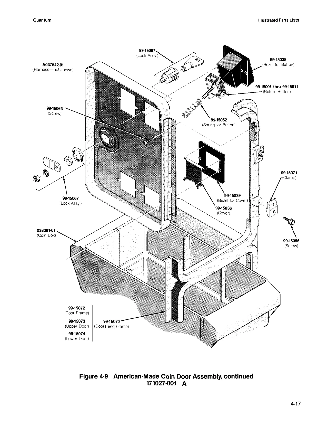
Part No. Description A037542-01 Harness Assembly 72-1414S #4-40 x %-Inch Cross-Recessed Pan-Head Steel Machine Screw 75-056 #6 Internal-Tooth Zinc-Plated Steel Lock Washer 75-9148 #4-40 Steel Machine Hex Nut 75-3414S #4-40 x %-Inch 82° Cross-Recessed Flat-Head Steel Machine Screw 99-15001 Coin Return Button with U.S. 25¢ Price Plate 99-15002 Coin Return Button with U.S. $1 Price Plate 99-15003 Coin Return Button with German 1 DM Price Plate 99-15004 Coin Return Button with German 2 DM Price Plate 99-15005 Coin Return Button with German 5 DM Price Plate 99-15006 Coin Return Button with Belgian 5 Fr Price Plate 99-15007 Coin Return Button with French 1 Fr Price Plate 99-15008 Coin Return Button with Japanese 100 Yen Price Plate 99-15009 Coin Return Button with British 10 Pence Price Plate 99-15010 Coin Return Button with Australian 20¢ Price Plate 99-15011 Coin Return Button with Italian 100 Lire Price Plate 99-15023 Base Plate 99-15025 Left Half of Coin Inlet 99-15026 Right Half of Coin Inlet 99-15027 Side Plate of Coin Return Box 99-15028 Base Plate of Coin Return Box 99-15029 Switch Bracket 99-15036 Metal Coin Return Cover 99-15038 Bezel for Coin Return Button 99-15039 Metal Bezel for Coin Return Cover 99-15040 Coin Return Lever 99-15042 Coin Switch for U.S. 25¢ 99-15052 Spring for Coin Return Button 99-15054 Pivot for Coin Return Lever 99-15055 Retaining Screw 99-15056 #4-40 x_%.Inch Cross-Recessed Pan-Head Steel Machine Screw 99-15060 Switch Cover 99-15063 Screw for Hinge 99-15066 Screw for Clamp 99-15067 Lock Assembly 99-15070 Doors and Frame 99-15071 Clamp for Frame 99-15072 Door Frame 99-15073 Upper Door 99-15074 Lower Door 99-15075 Switch Adjuster 038091-01 Coin Box (Not included in assembly) Acceptable substitute is part number A037491-01 170000-001 6.3 V Miniature Wedge-Base Incandescent Lamp 171006-035 Metal Coin Mechanism 179047-001 Lamp Base
Mllustrated Parts Lists Quantum
99-10140 (Pane! assy)
75-9488 Z (Locknut) ae 99-10116 (Lever)
99-10152 (Right coin inlet).
99-10096 (Fastener) 75-9448 (Hex nut)
99-10151 (Left coin inlet),
99-10080 (Lamp socket).
70-11-47 (Lamp)
/ 99-10104 (Bar retainer) . 72-9406S (Screw) 99-10147 (Harness)
® 99-10154 (i (Bracket assy.) s
a 99-10042 thru $9-10045 aeitise ~ a (Coin switch assy.) (Coin return box) oe ZZ S IN x
65-441C em (Coin switch ~ ~ : 99-10150 ON "(Switch cover) N 99-1075 thru $9-10078 — (Switch wire) 9910008 75-14128 (Retainer) (Screw)
Figure 4-9 American-Made Coin Door Assembly 171027-001 A
This page is a drawing, shown as the original scan.
Illustrated Parts Lists Quantum
American-Made Coin Door Assembly Parts List
Part No. Description
171006-035 Metal Coin Mechanism for U.S. $.25 65-441C Coin Switch 70-11-47 Miniature Bayonet Lamp 72-9406S #4-40 x %Inch Truss-Head Screw 72-HA1404C #4-40 x Y4-Inch Pan-Head Screw 72-JA1405B #4-40 x 31-Inch Pan-Head Screw 75-1412S #4-40 x 34-Inch Pan-Head Screw 75-9945 #4-40 Lock Nut 99-10008 Retainer 99-10042 Coin Switch Assembly for Belgium 5 Fr and U.S. $.25 99-10043 Coin Switch Assembly for German 1 DM, Japanese 100 Yen, Swiss 1 Fr 99-10044 Coin Switch Assembly for German 2 DM, Italian 100 L, U.S. $1.00 99-10045 Coin Switch Assembly for Australian $.20, German 5 DM, British 10 P 99-10068 Coin Return Chute 99-10075 Switch wire (included in coin switch assembly) 99-10076 Switch wire (included in coin switch assembly) 99-10077 Switch wire (included in coin switch assembly) 99-10078 Switch wire (included in coin switch assembly) 99-10080 Lamp socket 99-10081 Key holder 99-10096 Fastener 99-10104 Bar retainer 99-10105 Bar 99-10115, Spring 99-10116 Plastic Coin Return Lever 99-10117 Steel Coin Return Door 99-10118 Amber Coin Return Button 99-10119 Amber Coin Button for U.S. $.25 99-10134 Coin Button Cover 99-10139 Coin Door 99-10140 Coin Door Inner-Panel Assembly 99-10141 Diecast Coin Return Cover 99-10142 Diecast Button Housing 99-10143 Coin Door Frame 99-10144 Coin Door Channel Clip 99-10145 Offset Cam (includes 99-10148—Lock) 99-10146 Coin Inlet Chute Assembly 99-10147 American-Made Coin Door Harness 99-10149 Service Door 99-10150 Switch Cover 99-10151 Left Coin Inlet 99-10152 Right Coin inlet 99-10153 Coin Return Box 99-10154 Bracket Assembly
4-18
This page carries no recoverable text. It is a drawing or a photograph. See the original scan.
Mustrated Parts Lists
H. Printed-Circuit
Boards
039257-2008 (Retainer)
176015-110 (Screw)
A037701-02 (Cage)
4039297-21 (Game PCB)
178044-242 (Grommet)
175009-221 (Washer)
037873-01 (Spacer) 72-1604F (Screw) ‘A039430-03, (Ghield PCB)
%
Figure 4-10 Electromagnetic Interference (EMI) Cage Assembly and Printed-Circuit Board Mounting Hardware
4-20 [ / Quantum
721404F (Screw)
a “
Quantum llustrated Parts Lists
176015-110
175004-708 (Washer)
A035435.04 (Regulator/ Audio I! PCB)
Figure 4-10 Electromagnetic Interference (EMI) Cage Assembly and Printed-Circuit Board Mounting Hardware, continued Parts List
Part No. Description
A037701-02 EMI Cage (includes guide) A037430-03 EMI Shield PCB 72-1404F #4-40 x Y4-Inch Cross-Recessed Steel Screw 72-1604F #6-32 x Ya-Inch Cross-Recessed Steel Screw 03787301 Spacer 175009-221 Plastic Washer 176015-110 #10 x %Inch Cross-Recessed Pan-Head Screw 178045-442 Snap-In Fastener 034536-02 Foam Pad (not shown) 175004-708 #8 Flat Fiber Washer
4-21
Illustrated Parts Lists Quantum
Please see CO-221-01, supplement to TM-221, for information on this section.
Figure 4-11 EMI Shield PCB Assembly A037430-03 A
4-22
This page is a drawing, shown as the original scan.
Quantum Illustrated Parts Lists
DNIMVEO SIHL ONIAIEOSY SNOSH3d TI¥ O1 SOLON
bre) ‘I
Figure 412 Quantum Game Printed Circuit Board Assembly A039297-21 A
Quantum Illustrated Parts Lists
Quantum Game Printed-Circuit Board Assembly Parts List
| Designator | Description | Part No. |
Capacitors
| C2, C3 | 0.1 uF, +80, -20%, 50 V, Ceramic Capacitor | 122002-104 |
| C4 | 0.01 uF, 100 V, Radial-Lead Mylar Capacitor | 21-101103 |
| C8 | 0.047 uF, + 10%, 50 V, Axial-Lead Polycarbon Capacitor | 122010-473 |
| C9-C11 | 0.1 uF, +80, -20%, 50 V, Ceramic Capacitor | 122002-104 |
| C12 | 39 pF, +5%, 100 V, Axial-Lead Ceramic Capacitor | 128002-390 |
| C14-C20 | 0.1 uF, +80, -20%, 50 V, Ceramic Capacitor | 122002-104 |
| C21 | 0.0018 uF, + 10%, 1 kV, Ceramic Capacitor | 27-102182 |
| C25 | 0.047 uF, + 10%, 50 V, Axial-Lead Polycarbon Capacitor | 122010-473 |
| C26-C28 | 0.1 uF, +80, -20%, 50 V, Ceramic Capacitor | 122002-104 |
| C29 | 39 pF, +5%, 100 V, Axial-Lead Ceramic Capacitor | 128002-390 |
| C31 | 0.1 uF, +80, -20%, 50 V, Ceramic Capacitor | 122002-104 |
| C32 | 100 pF, +5%, 100 V, Axial-Lead Ceramic Capacitor | 122016-101 |
| C33-C36 | 0.1 pF, +80, -20%, 50 V, Ceramic Capacitor | 122002-104 |
| C37 | 150 pF, +5%, 100 V, Axial-Lead Ceramic Capacitor | 122016-151 |
| C38 | 39 pF, +5%, 100 V, Axial-Lead Ceramic Capacitor | 128002-390 |
| C39, C40 | 0.1 uF, +80, -20%, 50 V, Ceramic Capacitor | 122002-104 |
| C41 | 0.01 uF, +80, -20%, 25 V, Axial-Lead Ceramic Capacitor | 122005-103 |
| C42 | 10 pF, +5%, 100 V, Axial-Lead Ceramic Capacitor | 122016-100 |
| C44 | 100 pF 35 V Aluminum Electrolytic Axial-Lead Capacitor | 24-350107 |
| C45 | 22 uF 25 V Aluminum Electrolytic Axial-Lead Capacitor | 24-250226 |
| C46 | 100 pF 35 V Aluminum Electrolytic Axial-Lead Capacitor | 24-350107 |
| C47 | 22 uF 35 V Aluminum Electrolytic Axial-Lead Capacitor | 24-350226 |
| C48 | 22 uF 25 V Aluminum Electrolytic Axial-Lead Capacitor | 24-250226 |
| C49 | 0.1 uF, +80, -20%, 50 V, Ceramic Capacitor | 122002-104 |
| C51 | 1000 pF, +5%, 100 V, Axial-Lead Ceramic Capacitor | 122016-102 |
| C52-C60 | 1.0 uF 50 V Aluminum Electrolytic Axial-Lead Capacitor | 24-500105, |
| C61 | 1000 pF, +5%, 100 V, Axial-Lead Ceramic Capacitor | 122016-102 |
| C62 | 1.0 uF 50 V Aluminum Electrolytic Axial-Lead Capacitor | 24-500105 |
| C63 | 2220 pF, +5%, 100 V, Axial-Lead Ceramic Capacitor | 122016-221 |
| C64, C65 | 0.1 uF, +80, -20%, 50 V, Ceramic Capacitor | 122002-104 |
| 67-C73 | 0.1 uF, +80, -20%, 50 V, Ceramic Capacitor | 122002-104 |
| C74 | 1.0 uF 50 V Aluminum Electrolytic Axial-Lead Capacitor | 24-500105 |
| C75 | 0.1 uF, +80, -20%, 50 V, Ceramic Capacitor | 122002-104 |
| C76 | 100 pF, +5%, 100 V, Axial-Lead Ceramic Capacitor | 122016-101 |
| C77 | 39 pF, +5%, 100 V, Axial-Lead Ceramic Capacitor | 128002-390 |
| C78, C79 | 0.1 uF, +80, -20,%50 V, Ceramic Capacitor | 122002-104 |
| C80 | 0.022 uF, 100 V, Radial-Lead Mylar Capacitor | 21-101223 |
| C81 | 0.1 uF, +80, -20,%50 V, Ceramic Capacitor | 122002-104 |
| C82 | 100 uF 25 V Aluminum Electrolytic Axial-Lead Capacitor | 24-250107 |
| C83-C90 | 0.01 uF, +80, -20%, 25 V, Axial-Lead Ceramic Capacitor | 122005-103 |
| C91-C129 | 0.1 uF, +80, -20%, 50 V, Ceramic Capacitor | 122002-104 |
(Continued on next page)
4-25
illustrated Parts Lists Quantum
Quantum Game Printed-Circuit Board Assembly, continued Parts List
| Designator | Description | Part No. |
Diodes
| CR1 | Type-1N914, 250 mW, 100 V Switching Diode | 31-1N914 |
| CR3, CR4 | Type-1N100, 20 mA, 80 V Diode | 31-1N100 |
| CR5 | Type-1N754A, 400 mW, 6.8 V Zener Diode | 131002-001 |
| CR6 | Type-1N100, 20 mA, 80 V Diode | 31-1N100 |
| CR7 | Type-MV5053 Light-Emitting Diode | 38-MV5053, |
Inductors
| u | 100 pH, + 10% Inductor | 141002-001 |
| L2-4 | 1 pH, Ye W Inductor | 141007-001 |
Integrated Circuits
| VR1 | Voltage Regulator Integrated Circuit | 37-7815, |
| VR2 | Voltage Regulator Integrated Circuit | 37-7915 |
| 1B | Programmable Array Logic Integrated Circuit | 137290-001 |
| 1D | Type-74LS138 Integrated Circuit | 137177-001 |
| 1E, 1F | Type-74LS244 Integrated Circuit | 37-74LS244 |
| AK/L | Type-MC68000LC Integrated Circuit | 137289-001 |
| 1N | Type-74LS245 Integrated Circuit | 37-74LS245 |
| 1P | Type-74LS245 Integrated Circuit | 37-74LS245 |
| 2/3B, 2/3D | Audio I/O N-Channel MOS/LSI Custom Integrated Circuit | C012294-01 |
| 2P. | Type-74LS$245 Integrated Circuit | 37-74LS245 |
| 2R | Type-74LS74 Integrated Circuit | 37-74LS74 |
| 3A | Type-LM324 Integrated Circuit | 37-LM324 |
| 3c | Type-LM324 Integrated Circuit | 37-LM324 |
| 3P | Type-74LS245 Integrated Circuit | 37-74LS245 |
| 4D/E | Type-74LS245 Integrated Circuit | 37-74LS245, |
| 4E/F | Type-74LS245 Integrated Circuit | 37-74LS245 |
| 4FIH | Type-74S04 Integrated Circuit | 37-74LS04 |
| 4H/J | Type-74LS138 Integrated Circuit | 137177-001 |
| Ad | Type-74LS02 Integrated Circuit | 37-74LS02 |
| 4K | Type-74LS08 Integrated Circuit | 37-74LS08 |
| 4L | Type-74LS74 Integrated Circuit | 37-T4LS74 |
| 4M | Type-7406 Integrated Circuit | 37-7406 |
| 4N | Type-74S32 Integrated Circuit | 37-74S32 |
| 4P | Type-74LS00 Integrated Circuit | 37-74LS00 |
| 4R | Type-74LS393 Integrated Circuit | 37-74LS393 |
| 5A-5C | Type-74LS157 Integrated Circuit | 37-74LS157 |
| SF | Type-74LS32 Integrated Circuit | 37-74LS32 |
| 5H | Type-74LS174 Integrated Circuit | 37-74LS174 |
| SJ | Type-74S74 Integrated Circuit | 37-74S74 |
| 5K | Type-74LS27 Integrated Circuit | 37-74LS27 |
| 5L, 5M | Type-74LS161 Integrated Circuit | 37-74LS161 |
| 5N | Type-74LS273 Integrated Circuit | 37-74LS273 |
(Continued on next page)
4-26
Quantum Illustrated Parts Lists
Quantum Game Printed-Circuit Board Assembly, continued Parts List
| Designator | Description | Part No. |
| 5P | Type-74LS74 integrated Circuit | 37-74LS74 |
| 5R | Type-74LS393 Integrated Circuit | 37-74LS393 |
| 6B | Vector Generator Integrated Circuit | 127179-001 |
| 6F | Type-74S00 Integrated Circuit | 37-7400 |
| 6J | Type-74LS42 Integrated Circuit | 37-74LS42 |
| 6K | Type-74LS109 Integrated Circuit | 37-74LS109 |
| 6L | Type-74LS14 Integrated Circuit | 37-74LS14 |
| 6M | Type-74LS161 Integrated Circuit | 37-74LS161 |
| 6N | Type-74S02 Integrated Circuit | 37-74S02 |
| 6P | Type-74S02 Integrated Circuit | 37-74S02 |
| 6R | Type-74LS161 Integrated Circuit | 37-74LS 161 |
| 7A-7C | Type-74LS194 Integrated Circuit | 37-74LS194 |
| 7D | Type-74LS175 Integrated Circuit | 37-74LS175 |
| 7E | Type-74LS157 Integrated Circuit | 37-74LS157 |
| 7F | Type-82S25 Integrated Circuit | 90-7005 |
| 7H | Type-74LS00 Integrated Circuit | 37-74LS00 |
| 7d | Type-74LS175 Integrated Circuit | 37-74LS175 |
| 7K | Type-74LS32 Integrated Circuit | 37-74LS32 |
| 7L | Type-74S260 Integrated Circuit | 37-74S260 |
| 7M | Type-74LS161 Integrated Circuit | 37-74LS161 |
| 7N | Type-74LS164 Integrated Circuit | 37-74LS 164 |
| 7P | Type-74S 163 Integrated Circuit | 137274-001 |
| 8A-8C | Type-74LS194 Integrated Circuit | 37-74LS194 |
| 8D | Type-74LS273 Integrated Circuit | 37-74LS273 |
| 8F | Type-74LS175 Integrated Circuit | 37-74LS175 |
| 8H | Type-74LS399 Integrated Circuit | 37-T4LS399 |
| Bu | Type-74LS175 Integrated Circuit | 37-74LS175 |
| 8K | Type-74LS32 Integrated Circuit | 37-74LS32 |
| 8L | Type-74S02 Integrated Circuit | 37-74S02 |
| 8M, 8N | Type-74LS191 Integrated Circuit | 37-74LS191 |
| 8P. | Type-74S04 Integrated Circuit | 37-74S04 |
| 9B | 12-Bit DAC Integrated Circuit | 137158-002 |
| 9D | 8-Bit DAC Integrated Circuit | 137159-001 |
| 9F/H | 12-Bit DAC Integrated Circuit | 137158-002 |
| ou | Type-74S260 Integrated Circuit | 37-74S260 |
| OK | Type-74LS 109 Integrated Circuit | 37-74LS 109 |
| OL | Type-74LS175 Integrated Circuit | 37-74LS175 |
| 9M, 9N | Type-74LS244 Integrated Circuit | 37-74LS244 |
| 9P. | Type-74LS191 Integrated Circuit | 37-74LS191 |
| 10A | Type-TL082 Integrated Circuit | 37-TLO82CP |
| 10B | Quad Analog Switch Integrated Circuit | 37-13201 |
| 10D | Type-TL082 Integrated Circuit | 37-TLO82CP |
| 10E | Quad Analog Switch Integrated Circuit | 37-13201 |
| 10J | Type-74LS04 Integrated Circuit | 37-74LS04 |
(Continued on next page)
4-27
Illustrated Parts Lists
Quantum Game Printed-Circuit Board Assembly, continued Quantum
Parts List
| Designator | Description | Part No. |
| 10K | Type-74LS86 Integrated Circuit | 37-74LS86 |
| 10N | Schmitt Trigger Integrated Circuit | 37-4584B |
| 10P | Type-74LS157 Integrated Circuit | 37-74LS157 |
| 10R | Type-74LS74 Integrated Circuit | 37-74LS74 |
| 11B, 11C | Multiplier Integrated Circuit | 37-1495 |
| 11D/E | Type-TL082 Integrated Circuit | 37-TLO82CP |
| 11P | Schmitt Trigger Integrated Circuit | 37-4584B |
| 12B, 12C | Multiplier Integrated Circuit | 37-1495 |
| 12D/E | Type-TL082 Integrated Circuit | 37-TLOB2CP |
| 12M/N | Type-TL082 Integrated Circuit | 37TLO82CP |
Miscellaneous
Nylon Snap-In Fastener 81-4302 Test Point Acceptable substitute is part no. 020670-01 179051-002
| 1 | 12.096 MHz Crystal | 144000-001 |
| 4B | 8-Station Single-Throw Dual-Inline Package Bit Switch | 66-118P 1t |
| 4c/iD | 8-Station Single-Throw Dual-Inline Package Bit Switch | 66-118P It |
Programmable Read-Only Memories
| 2E | Electrically Programmable Read-Only Memory | 136016-001 |
| 2F | Electrically Programmable Read-Only Memory | 136016-002 |
| 2HIJd | Electrically Programmable Read-Only Memory | 136016-003 |
| 2K | Electrically Programmable Read-Only Memory | 136016-004 |
| aL | Electrically Programmable Read-Only Memory | 136016-005 |
| 3E | Electrically Programmable Read-Only Memory | 136016-006 |
| 3F | Electrically Programmable Read-Only Memory | 136016-007 |
| 3Hid | Electrically Programmable Read-Only Memory | 136016-008 |
| 3K | Electrically Programmable Read-Only Memory | 136017-009 |
| 3L | Electrically Programmable Read-Only Memory | 136017-010 |
| 6H | Programmable Read-Only Memory | 136002-125 |
Random-Access Memories
| 2M, 2N | Random-Access Memory | 137211-001 |
| 3M, 3N | Random-Access Memory | 137211-001 |
| 3R | Random-Access Memory | 137288-001 |
| SD, 5E | Random-Access Memory | 137211-001 |
| 6D, 6E | Random-Access Memory | 137211-001 |
Resistors
| R26, R27 | 820 2, +5%, Vs W Resistor | 110000-821 |
| R30, R31 | 75 kQ, +1%, % W Resistor | 110003-752 |
| R32, R33 | 470 Q, +5%, va W Resistor | 110000-471 |
| R34 | 2.7 kQ, +5%, % W Resistor | 110000-272 |
(Continued on next page)
4-28
Quantum Illustrated Parts Lists
Quantum Game Printed-Circuit Board Assembly, continued Parts List
| Designator | Description | Part No. | |
| R35 | 680 2, +5%, % W Resistor | 110000-681 | |
| R36 | 2.2 kQ, +5%, va W Resistor | 110000-222 | |
| R37 | 3.9 kQ, +5%, % W Resistor | 110000-392 | |
| R38 | 470 2, +5%, % W Resistor | 110000-471 | |
| R39 | 3.9 kQ, +5%, Ys W Resistor | 110000-392 | |
| R40 | 10 kQ, +5%, % W Resistor | 110000-103 | |
| R41 | 5.6 kQ, +5%, % W Resistor | 110000-562 | |
| R44, R45 | 2.2 kQ, +5%, Ys W Resistor | 110000-222 | |
| R46 | 10 kQ, +5%, % W Resistor | 110000-103 | |
| R47 | 2 kQ Horizontal Potentiometer | 119002-202 | |
| R50 | 2.2 kQ, +5%, V4 W Resistor | 110000-222 | |
| R51 | 470 2, +5%, % W Resistor | 110000-471 | |
| R52 | 3.9 kQ, +5%, % W Resistor | 110000-392 | |
| R53 | 1kQ, +5%, ¥% W Resistor | 110000-102 | |
| R54 | 680 2, +5%, % W Resistor | 110000-681 | |
| RSS | 820 2, +5%, % W Resistor | 110000-821 | |
| R58 | 7.5 kQ, | 1%, % W Resistor | 110003-752 |
| R59 | 470 2, +5%, Y% W Resistor | 110000-471 | |
| R60 | 2.7 kQ, +5%, V4 W Resistor | 110000-272 | |
| R61 | 680 2, +5%, % W Resistor | 110000-681 | |
| R62, R63 | 470 Q, +5%, Ys W Resistor | 110000-471 | |
| R64 | 2.2 kQ, +5%, % W Resistor | 110000-222 | |
| R65, R66 | 3.9 kQ, +5%, Ys W Resistor | 110000-392 | |
| R67 | 10 kQ, +5%, ¥% W Resistor | 110000-103 | |
| R69 | 2.2 kQ, +5%, % W Resistor | 110000-222 | |
| R70 | 2.2 kQ, +5%, Ys W Resistor | 110000-222 | |
| R71 | 5.6 kQ2, +5%, v4 W Resistor | 110000-562 | |
| R73 | 10 kQ, +5%, % W Resistor | 110000-103 | |
| R74 | 2 kQ Horizontal Potentiometer | 119002-202 | |
| R76 | 1.2 kQ, +5%, % W Resistor | 110000-122 | |
| R77 | 2.2 kQ, +5%, Vs W Resistor | 110000-222 | |
| R78, R79 | 3.9 kQ, +5%, V4 W Resistor | 410000-392 | |
| R80 | 1k2, +5%, Ys W Resistor | 110000-102 | |
| R81 | 15 kQ, +5%, % W Resistor | 110000-153 | |
| R82 | 1kQ, +5%, 4 W Resistor | 110000-102 | |
| R83 | 10 k2, +5%, % W Resistor | 110000-103 | |
| Re4 | 560 2, +5%, % W Resistor | 110000-561 | |
| R85-R87 | 7.5 kQ, +1%, % W Resistor | 110003-752 | |
| R88 | 200 2 Horizontal Potentiometer | 119002-201 | |
| Reg | 7.5kQ, +1%, ¥ W Resistor | 110003-752 | |
| R90 | 100 2, + 1%, % W Resistor | 110000-101 | |
| RO1 | 7.5 kQ, +1%, % W Resistor | 110003-752 | |
| R92 | 200 | Horizontal Potentiometer | 119002-201 |
| R93 | 7.5 kQ, +1%, % W Resistor | 110003-752 |
(Continued on next page)
4-29
Illustrated Parts Lists Quantum
Quantum Game Printed-Circuit Board Assembly, continued Parts List
| Designator | Description | Part No. | |
| R94 | 100 2, + 1%, ¥% W Resistor | 110000-101 | |
| R95, RIS | 7.5 kQ, +1%, }, W Resistor | 110003-752 | |
| R97 | 3.9 kQ, +5%, V4 W Resistor | 110000-392 | |
| R106 | 7.5 kQ, + 1%, | W Resistor | 110003-752 |
| R108 | 270 kQ, +5%, Y2 W Resistor | 110000-271 | |
| R110-R117 | 3.3 kQ, +5%, Vs W Resistor | 110000-332 | |
| R118 | 10 kQ, +5%, % W Resistor | 110000-103 | |
| R119 | 1kQ, +5%, Ys W Resistor | 110000-102 | |
| R120-R128 | 10 kQ, +5%, V4 W Resistor | 110000-103 | |
| R129 | 1kQ, +5%, %4 W Resistor | 110000-102 | |
| R130 | 1.8kQ, +5%, % W Resistor | 110000-182 | |
| R131 | 2.2 kKQ, +5%, V4 W Resistor | 110000-222 | |
| R132 | 1.8 k2, +5%, 4 W Resistor | 110000-182 | |
| R133 | 2.2 kQ, +5%, % W Resistor | 110000-222 | |
| R134 | 3.3 kQ, +5%, % W Resistor | 110000-332 | |
| R135 | 2.2 kQ, 5%, v4 W Resistor | 110000-222 | |
| R136 | 6.8 kQ, +5%, % W Resistor | 110000-682 | |
| R137-R139 | 470 Q, +5%, V4 W Resistor | 110000-471 | |
| R140 | 1.2 kQ, +5%, % W Resistor | 110000-122 | |
| R141 | 2.2 kQ, + 5%, % W Resistor | 110000-222 | |
| R142 | 4.7 kQ, +5%, % W Resistor | 110000-472 | |
| R143 | 10 kQ, +5%, % W Resistor | 110000-103 | |
| R144 | 22 kQ, +5%, 4 W Resistor | 110000-223 | |
| R145 | 3.3 kQ, +5%, Ys W Resistor | 110000-332 | |
| R146 | 510 2, +5%, % W Resistor | 110000-511 | |
| R147, R148 | 1kQ, +5%, V4 W Resistor | 110000-102 | |
| R149 | 470 Q, +5%, %4 W Resistor | 110000-471 | |
| R151-R152 | 470 Q, +5%, % W Resistor | 110000-471 | |
| R153 | 1kQ, +5%, % W Resistor | 110000-102 | |
| R155-R159 | 1kQ, +5%, % W Resistor | 110000-102 | |
| R160-R162 | 470 2, +5%, v4 W Resistor | 410000-471 | |
| R163 | 10 k2, +5%, % W Resistor | 110000-103 | |
| R164, R165 | 220 Q, +5%, % W Resistor | 110000-221 | |
| R166-R172 | 1kQ, +5%, % W Resistor | 110000-102 | |
| R173 | 10 kQ, +5%, % W Resistor | 110000-103 | |
| R174 | 68 kQ, +5%, V4 W Resistor | 410000-683 | |
| R175 | 15 k2, +5%, V4 W Resistor | 110000-153 | |
| R176 | 1kQ, +5%, v4 W Resistor | 110000-102 | |
| R177, R178 | 10 kQ, +5%, % W Resistor | 110000-103 | |
| R179 | 220 Q, +5%, Vs W Resistor | 110000-221 | |
| R180-R187 | 100 k2, +5%, %4 W Resistor | 110000-104 | |
| R188-R203 | 4.7 kQ, +5%, 4 W Resistor | 110000-472 | |
| R204 | 290 kQ, +5%, % W Resistor | 110000-224 | |
| R205 | 1kQ, +5%, v4 W Resistor | 110000-102 |
(Continued on next page)
4-30
Quantum
Quantum Game Printed-Circuit Board Assembly, continued Illustrated Parts Lists
Parts List
| Designator | Description | Part No. |
| R206-R209 | 290 kQ, +5%, % W Resistor | 110000-224 |
| R210 | 1kQ, +5%, % W Resistor | 110000-102 |
| R211-R213 | 220 kQ, +5%, %4 W Resistor | 110000-224 |
| R214 | 150 Q, +5%, % W Resistor | 110000-151 |
| R215 | 10 kQ, +5%, % W Resistor | 110000-103 |
| R216, R217 | 4.7 kQ, +5%, Vs W Resistor | 110000-472 |
| R218-R222 | 1kQ, +5%, Ya W Resistor | 110000-102 |
| R223 | 220 2, +5%, % W Resistor | 110000-221 |
| R224-R226 | 100 2, +5%, ¥ W Resistor | 110000-101 |
| RV1, RV2 | 8 V Variable Resistor | 110004-001 |
Sockets
| AKL, | 64-Contact Medium-Insertion-Force Integrated Circuit Socket | 79-42C64 |
| 2/3B, 2/3D. | 40-Contact Medium-Insertion-Force Integrated Circuit Socket | 79-42C40 |
| 2E, 2F | 28-Contact Medium-insertion-Force Integrated Circuit Socket | 79-42C28 |
| 2HId | 28-Contact Medium-Insertion-Force Integrated Circuit Socket | 79-42028 |
| 2K, 2L | 28-Contact Medium-Insertion-Force Integrated Circuit Socket | 79-42C28 |
| 2M, 2N | 24-Contact Medium-Iinsertion-Force Integrated Circuit Socket | 79-42C24 |
| 3E, 3F | 28-Contact Medium-Insertion-Force Integrated Circuit Socket | 79-42C28 |
| SHI | 28-Contact Medium-Insertion-Force Integrated Circuit Socket | 7179-42028 |
| 3K, 3L | 28-Contact Medium-Insertion-Force Integrated Circuit Socket | 79-42C28 |
| 3M, 3N | 24-Contact Medium-Insertion-Force Integrated Circuit Socket | 79-42C24 |
| 5D, 5E | 24-Contact Medium-Insertion-Force Integrated Circuit Socket | 79-42C24 |
| 6B | 40-Contact Medium-Insertion-Force Integrated Circuit Socket | 79-42C40 |
| 6D, 6E | 24-Contact Medium-Insertion-Force Integrated Circuit Socket | 79-42C24 |
Transistors
| Q7 | Type-2N3904, 350 mW, 60 V NPN Transistor | 34-2N3904 |
| Q8 | ‘Type-2N3906, 1 W, 40 V PNP Transistor | 33-2N3906 |
| Q9-Q11 | Type-2N3904, 350 mW, 60 V NPN Transistor | 34-2N3904 |
| Qr2 | Type-2N3906, 1 W, 40 V PNP Transistor | 33-2N3906 |
| Q13, Q14 | Type-2N3904, 350 mW, 60 V NPN Transistor | 34-2N3904 |
| Q15, Q16 | Type-2N6044, 8 A, 80 V NPN Transistor | 34-2N6044 |
| Qi7 | Type-2N3904, 350 mW, 60 V NPN Transistor | 34-2N3904 |
4-31
Mustrated Parts Lists Quantum
NOTICE TO ALL PERSONS RECEIVING THIS DRAWING CONFIDENTIAL Reproduction forbidden without the specific writlen permission of Atari, inc,, Sunnyvale, CA. This drawing is ny conditionally issued. and ‘neither receipt nor possession tnereot conters ar transters any righ! in, oF license to use, the subject matter of the drawing or any design or fecrinical intormation shawn thereon, nor any right to reproduce this drawing or any part thereo! Except for manutacture by vendors of Alan Inc. and for manutacture under ine corpoiation’s written license, no right 10 reproduce this drawing is granted or the subject ma ler thereot uness by wnitlen agreement with ar written permis sion trom the corporation
Acceptable substitute is part no. A035435-02.
R24, 10 Tw} oO
TIP32 _ TOAZ002A TDA2002ZA Nae inaco2z Q5 Q7
- cR+ Ti le m 7 RSE a, C70 S cic cans [3s1R3 ce@Z) |o| cst 0 cea saris [0S | P2708) 614
Figure 413 Regulator/Audio !i PCB Assembly A035435-04 C
4-32
Quantum Wlustrated Parts Lists
Regulator/ Audio II Printed-Circuit Board Assembly Parts List
| Designator | Description | Part No. |
Capacitors
| C1 | 470 uF, 25 V, Aluminum Electrolytic Fixed Axial-Lead Capacitor | 24-250477 |
| c2 | 0.001 uF, 50 V, Ceramic-Disc Axial-Lead Capacitor | 122002-102 |
| C3 | 0.1 uF, 50 V, Ceramic-Disc Axial-Lead Capacitor | 122002-104 |
| C4 | 470 uF, 25 V, Aluminum Electrolytic Fixed Axial-Lead Capacitor | 24-250477 |
| cé | 0.01 uF, 25 V Minimum, Ceramic-Disc Axial-Lead Capacitor Acceptable | 100015-103 |
substitute is part no. 122005-103
| C6 | 0.22 uF, 25 V, Ceramic-Disc Axial-Lead Capacitor | 122004-224 |
| c7 | 0.001 uF, 50 V, Ceramic-Disc Axial-Lead Capacitor | 122002-102 |
| ce | 0.22 uF, 25 V, Ceramic-Disc Axial-Lead Capacitor | 122004-224 |
| C9, C10 | 3300 uF, 35 V, Aluminum Electrolytic Fixed Axial-Lead Capacitor | 24-350338 |
| ci | 0.1 uF, 50 V, Ceramic-Disc Axial-Lead Capacitor | 122002-104 |
| C12 | 470 uF, 25 V, Aluminum Electrolytic Fixed Axial-Lead Capacitor | 24-250477 |
| C13 | 1000 pF, 25 V, Aluminum Electrolytic Fixed Axial-Lead Capacitor | 24-250108 |
| C14 | 0.01 uF, 25 V Minimum, Ceramic-Disc Axial-Lead Capacitor | 100015-103 |
Acceptable substitute is part no, 122005-103
| C15 | 0.22 uF, 25 V, Ceramic-Disc Axial-Lead Capacitor | 122004-224 |
| CIE | 0,001 uF, 50 V, Ceramic-Disc Axial-Lead Capacitor | 122002-102 |
| C17 | 0.22 uF, 25 V, Ceramic-Disc Axial-Lead Capacitor | 122004-224 |
| C18, C19 | 3300 uF, 35 V, Aluminum Electrolytic Fixed Axial-Lead Capacitor | 24-360338 |
| C20, C21 | 0.1 uF, 50 V, Ceramic-Disc Axial-Lead Capacitor | 122002-104 |
Diodes
| CR1, C4 | Type-1N4002, 1 A, 100 V Silicon Rectifier Diode | 31-1N4002 |
| CR5-CR8 | Type-1N5401, 3 A, 100 V Silicon Rectifier Diode | 31-1N5401 |
Integrated Circuits
| Qi | Type-LM305, 5 V, Linear Voltage Regulator | 37-LM305, |
| Q5 | Type-TDA2002A, 8 W, Linear Audio Amplifier Integrated Circuit | 137151-002 |
| Q7 | Type-TDA2002A, 8 W, Linear Audio Amplifier Integrated Circuit | 137151-002 |
Resistors
| R1 | 270 Q, +5%, V4 W Resistor | 110000-271 |
| R3 | 33 Q, +5%, Ys W Resistor | 110000-330 |
| R4 | 100 2, +5%, Ys W Resistor | 110000-101 |
| R5 | 2.7 2, +5%, 1 W Resistor | 110009-027 |
| R6 | 3.9 kQ, +5%, % W Resistor | 110000-392 |
| R7 | 75 kQ, +5%, vs W Resistor | 110000-752 |
| R8 | 1 kQ Horizontal PCB-Mounting Cermet Potentiometer Acceptable | 119002-102 |
substitute is part no. 19-315102
| RQ | 220 2, +5%, Ve W Resistor | 110001-221 |
| R10 | 12, +5%, Ys W Resistor | 110000-010 |
| Rit | 10 2, 5%, % W Resistor | 110000-100 |
| R12 | 100 2, +5%, % W Resistor | 110000-101 |
| R13, R14 | 10 kQ, +5%, % W Resistor | 110000-103 |
(Continued on next page)
Illustrated Parts Lists Quantum
Regulator/Audio Il PCB Assembly Parts List, continued
| Designator | Description | Part No. |
| Rig | 12, +5%, Vs W Resistor | 110000-010 |
| R20 | 10 2, +5%, 4 W Resistor | 110000-100 |
| R21 | 220 2, +5%, V2 W Resistor | 110001-221 |
| R22 | 100 2, 5%, V4 W Resistor | 110000-101 |
| R24 | 0.1 9, +3%, 7 W Wirewound Resistor | 19-100P 1015 |
| R27, R28 | 1kQ, +5%, V4 W Resistor | 110000-102 |
| R29, R30 | 10 2, 5%, V4 W Resistor | 110000-100 |
| R32, R33 | 5.6 kQ, +5%, V4 W Resistor | 110000-562 |
Transistors
| Q2 | Type-TIP32 PNP Power Transistor | 33-TIP32 |
| Q3 | Type-2N3055 NPN Silicon Transistor | 34-2N3055 |
Mechanical Parts
| J6 | 6-Position Connector Receptacle | 79-58306 |
| J7 | 9-Position Connector Receptacle | 79-58308 |
| J8 | 4-Position Connector Receptacle | 79-58354 |
| Jg | 6-Position Connector Receptacle | 79-58306 |
| J10 | 12-Position Connector Receptacle | 79-58346 |
| Q2 | #6-32 x Y%-Inch Binder-Head Nylon Screw | 75-F60405 |
| Q3 | #6-32 Nut/Washer Assembly | 75-99516 |
| Q3 | Thermally Conductive Silicon Insulator | 78-16008 |
| Qs | Thermally Conductive Silicon insulator | 78-16008 |
| Q5, Q7 | #6 x ¥%-Inch Cross-Recessed Pan-Head Thread-Forming Type-AB Zinc- | 72-6606S |
Plated-Steel Screw
Heat Sink 034531-01 Test Point Acceptable substitute is part no. 020670-01 179051-001
4-34
Quantum Illustrated Parts Lists
I. Color X-Y Power Supply Assembly
A021084-xx (Voit. Plugs) 29-053 (Capacitor)
034554-01 (Fuse Cover)
79-4411001 (Fuse Post) 78-70501SC | = (Cap. Bracket) mL ih 46-2017002 aS > (Fuse)
A035891-02 (Fuse Harness) 034482.02 “4 (Chassis) 46-301203 (Fuse)
037639-01 (Label)
78-2708 (Bushing)
A034630-01 79-3206 (Fuse Block} (Filter Assy.)
037641-01 (Label) 46-2014002 (Fuses)
79-15021001 A035890-01 (Term. Block) \ (Pwr. Harness) A034629-01 3A-MDA3501 (A.C. Harn.) (Rectifier)
Figure 414 Color X-Y Power Supply Assembly A037396-xx D
4-35
Illustrated Parts Lists Quantum
Color X-Y Power Supply Assembly Parts List
Part No. Description (Reference Designations in Bold)
| A021084-01 | Voltage Plug for 100 V_ | (violet) |
| A021084-02 | Voltage Plug for 120 V | (yellow) |
| A021084-04 | Voltage Plug for 220 V | (b/ue) |
| A021084-05 | Voltage Plug for 240 V | (brown) |
A034629-01 AC Harness Assembly
| A034630-01 | RFI Filter Assembly | (FL1) |
A035890-01 Power Harness Assembly A035891-02 Fuse Harness Assembly A037395-01 Color X-Y Transformer Assembly (1) 29-053 27,000 uF 15 VDC Electrolytic Capacitor (C1) 3A-MDA3501 Type-MDA 3501 Bridge Rectifier (CR1)
| 46-2014002 | 4 A, 250 V, 3AG Slow-Blow Glass Cartridge-Type Fuse | (F2, F4-F6) |
| 46-2017002 | 7 A, 250 V, 3AG Slow-Blow Glass Cartridge-Type Fuse | (F1) |
| 46-301203 | 20 A, 32 V, 3AG Slow-Blow Glass Cartridge-Type Fuse | (F3) |
78-2708 Nylon Type 6/6 Hole Bushing with %-Inch Inside Diameter x %-Inch Outside Diameter x Ya-Inch Thick 78-70501SC 2-\nch Diameter Capacitor Mounting Bracket 79-15021001 2-Circuit Single-Row Terminal Block 79-3206 5-Position 3AG Fuse Block with %4-Inch Quick-Disconnect Terminals 79-4411001 Panel-Mounting Non-Indicating 3AG Cartridge-Type Fuse Post 034482-02 Power Supply Chassis Base 034544-01 Fuse Block Cover 037243-01 Metal Base Plate (not shown in illustration)
| 037639-01 | Label for Fuse Value | (F1) |
| 037641-01 | Label for Fuse Values | (F2-F6) |
Line Voltage Range Voltage Selection Plug Wire Color 90-110 VAC (100) Violet 105-135 VAC (120) Yellow 200-240 VAC (220) Blue 220-260 VAC (240) Brown
4-36
Quantum
Glossary of Terms
Ac Alternating current; from zero it rises to a maximum positive level, then passes through zero again to a maximum negative level. ACTIVE STATE The true state of a signal. For example: The active state for START is low.
ADDRESS A value that identifies a specific location of data in memory; normally expressed in hexadecimal notation. ANALOG Measurable in an absolute quantity (as opposed to on or off). Analog devices are volume controls, light dimmers, stereo amplifiers, etc. ANODE The positive (arrow) end of a diode.
AMPLIFIER A device used to increase the strength of an applied signal. AMPLITUDE The maximum instantaneous value of a waveform pulse from zero. ASTABLE Having no normal state. An astable device will free-run or oscillate as long as operating voltage is applied. The oscillation frequency is usually controlled by external circuitry. AUXILIARY COIN SWITCH A momentary-contact pushbutton switch with a black cap located on the utility panel. The auxiliary coin switch adds credits to the game without activating the coin counter. BEZEL A cut, formed, or machined retention device, such as the conical device used to mount a pushbutton switch to a control panel, or the formed device used to frame the video display screen. BIDIRECTIONAL Able to send or receive data on the same line (e.g., the data bus of a microprocessor). BINARY A number system that expresses all values by using two digits (0 and 1). BIT A binary digit; expressed as a 1 or ad. BLANKING Turning off the beam on a cathoderay tube during retrace. BLOCK DIAGRAM A drawing in which functional circuitry units are represented by blocks. Very useful during initial troubleshooting. BUFFER
- An isolating circuit designed to eliminate the reaction of a driven circuit on the circuits driving it (e.g., a buffer amplifier).
- A device used to supply additional drive capability. BUS An electrical path over which information is transferred from any of several sources to any of several destinations.
CAPACITOR A device capable of storing electrical energy. A capacitor blocks the flow of DC current while allowing AC current to pass.
CATHODE The negative end of a diode. CHIP An integrated circuit comprising many circuits on a single wafer slice.
CLOCK A repetitive timing signal for synchronizing system functions.
COINCIDENCE Occurring at the same time. COIN COUNTER A 6-digit electro-mechanical device that counts the coins inserted in the coin mechanism(s). COIN MECHANISM A device on the inside of the coin door that inspects the coin to determine if the correct coin has been inserted. COMPLEMENTARY Having opposite states, such as the outputs of a flip-flop. COMPOSITE SYNC Horizontal and vertical synchronization pulses that are bused together into a single signal. This signal provides the timing necessary to keep the display in synchronization with the game circuitry. Glossary
COMPOSITE VIDEO Complete video signal from the game system to drive the display circuitry, usually comprising H SYNC, V SYNC, and the video. CREDIT One play for one person based on the game switch settings. CRT Cathode-ray tube. DATA General term for the numbers, letters, and symbols that serve as input for device processing. DARLINGTON A two-transistor amplifier that provides extremely high gain. bc Direct current, meaning current flowing in one direction and of a fixed value. DEFLECTION YOKE Electro-magnetic coils around the neck of a cathode-ray tube. One set of coils deflects the electron beam horizontally and the other set deflects the beam vertically. DIAGNOSTICS A programmed routine for checking circuitry. For example: the self-test is a diagnostic routine. DIODE A semiconductor device that conducts in only one direction. DISCRETE Non-integrated components, such as resistors, capacitors, and transistors. DMA Direct memory access. DMA is a process of accessing memory that bypasses the microprocessor logic. DMA is normally used for transferring data between the input/output ports and memory. DOWN TIME The period during which a game is malfunctioning or not operating correctly due to machine failure. EAROM Electrically alterable read-only memory (See ROM). The EAROM is a memory that can be changed by the application of high voltage. FLYBACK A step-up transformer used in a display to provide the high voltage.
Gut
Glossary
GATE
- A circuit with one output that responds when and only when a certain combination of pulses is present at the inputs.
- A circuit in which one signal switches another signal on and off.
- To control the passage of a pulse or signal. HARNESS A prefabricated assembly of insulated wires and terminals ready to be attached to a piece of equipment. HEXADECIMAL A number system using the equivalent of the decimal number 16 as a base. The symbols 0-9 and A-F are usually used. IMPLODE To burst inward; the inward collapse of a vacuum tube. vo {nput/Output. IRQ Interrupt request. {RQ is a controt signal to the microprocessor that is generated by external logic. This. signal tells the microprocessor that external logic needs attention. Depending on the program, the processor may or may not respond. LED The abbreviation for a light-emitting diode. LOCKOUT COIL Directs coins into the coin return box when there is no power to the game. LOGIC STATE The binary (1 or 0) value at the node of a logic element or integrated circuit during a particular time. Also called the logic level. The list below shows the voltage levels corresponding to the logic states (levels) in a TTL system. Logic 0, Low = 0 VDC to +0.8 VDC Grey Area (Tri-State Level) = +0.8 VDC to +2.4 VDC Logic 1, High = +2.4VDC to +5 VDC MULTIPLEXER A device that takes several lowspeed inputs and combines them into one high-speed data stream for si-
iuhaneous transmission on a single
ine.
GL-2 NMI Non-maskable interrupt. NMI is a request for service by the microprocessor from external logic. The microprocessor cannot ignore this interrupt request. PAGE A subsection of memory. A read-only memory device (see ROM) is broken into discrete blocks of data. These blocks are called pages. Each block has X number of bytes. PCB The abbreviation for a printed-circuit board. PHOTOTRANSISTOR A transistor that is activated by an external light source. POTENTIOMETER
- A resistor that has a continuously moving contact which is generally mounted on a moving shaft. Used chiefly as a voltage divider. Also called a pot (slang).
- An instrument for measuring a voltage by balancing it against a known voltage. RAM Random-access memory. A device for the temporary storage of data. RASTER-SCAN DISPLAY A display system whereby images are displayed by continuously scanning the cathode-ray tube horizontally and vertically with an electron beam. The display system controls the intensity of the electron beam. RETRACE In a raster-scan display, retrace is the time during which the cathoderay tube electron beam is resetting either from right to left or from bottom to top. RESISTOR A device designed to have a definite amount of resistance. Used in circuits to limit current flow or to provide a voltage drop. ROM Read-only memory. A device for the permanent storage of data. SIGNATURE ANALYSIS A process of isolating digital logic faults at the component level by means of special test equipment called signature analyzers. Basically, signature analyzers (e.g., the ATARI® CAT Box) convert lengthy bit Quantum
streams into four-digit hexadecimal signatures. The signature read by the analyzer at each circuit node is then compared with the known good signature for that node. This process continues until a fault is located. TROUBLESHOOT The process of locating and repairing a fault. VECTOR A line segment drawn between specific X and Y coordinates on a cathode-ray tube. WATCHDOG A counter circuit designed to protect the microprocessor from self-destruction if a program malfunction occurs. If a malfunction does occur, the counter applies continuous pulses to the reset line of the micro- Processor, which causes the microprocessor to keep resetting. X-Y DISPLAY A display system whereby images are displayed with vectors. ZENER DIODE A special diode used as a regulator. Its main characteristic is breaking down at a specified reverse-bias (Zener) voltage.
Quantum™ 1st printing
YOUR COMMENTS, PLEASE!
Your comments will assist Atari in improving our publications. The comments are an important part of preparing for revisions of game manuals. Please write in the space below. No postage stamp is necessary if mailed in the U.S.A.
If you have any technical questions about certain ATARI games products, or are requesting additional publications, we will immediately forward your note to the appropriate person.
Page: Comments:
Fill in if you wish a reply
Name.
Firm G Distributor
Address © Operator
City State Zip ( Other,
Area Code Phone
First told
No Postage Necessary Ht maied in the United States
BUSINESS REPLY MAIL
FIRST CLASS PERMIT NO. 1004 SUNNYVALE, CA POSTAGE WILL BE PAID BY ADDRESSEE
Atari, Inc. Attn.: Field Service/Coin-Op Di P. O. Box 427 Sunnyvale, California 94086 ion
Second fold
wol4
NOTES
NOTES
PES BGS RON BEI BS RN BE ER 28
LSE ES SS
Warranty
Seller warrants that its printed-circuit boards and parts thereon are free from defects in material and workmanship under normal use and service for a period of ninety (90) days from date of shipment. Seller warrants that its video displays (in games supplied with displays) are free from defects in material and workmanship under normal use and service for a period of thirty (30) days from date of shipment. None of the Seller's other products or parts thereof are warranted.
lf the products described in this manual fail to conform to this warranty, Sellers’ sole liability shall be, at its option, to repair, replace, or credit Buyer's account for such products which are returned to Seller during said warranty period, provided
- Seller is promptly notified in writing upon discovery by Buyer that said products are defective:
- Such products are returned prepaid to Sellers’ plant; and
- Seller's examination of said products discloses to Seller's satisfaction that such alleged defects existed and were not caused by accident, misuse, neglect, alteration, improper repair, installation or improper testing
In no event shall Seller be liable for loss of profits, loss of use, incidental or consequential damages.
Except for any express warranty set forth in a written contract between Seller and Buyer which contract supersedes the terms of this order, this warranty is expressed in lieu of all other warranties expressed or implied, including the implied warranties of merchantability and fitness for a particular purpose, and of all other obligations or liabilities on the Seller's part, and it neither assumes nor authorizes any other person to assume for the Seller any other liabilities in connection with the sale of products under this order.
The use of any non-Atari parts may void your warranty, according to the terms of the warranty. The use of any non-Atari parts may also adversely affect the safety of your game and cause injury to yourself and others. Be very cautious in using non-Atari-supplied components with our games, in order to insure your safety.
Atari distributors are independent, being privately owned and operated. In their judgment they may sell parts or accessories other than Atari parts or accessories. Atari cannot be responsible for the quality, suitability or safety of any non-Atari part or any modification including labor which is performed by such distributor.
This document is and contains confidential trade secret information of Atari, Inc.
This document is loaned under confidential custody for the sole purpose of operation, maintenance or repair of Atari equipment and may not be used by or disclosed to any person for any other purpose whatever, and remains the property of Atari, Inc.
Neither it nor the information it contains may be reproduced, used, or disclosed to persons not having a need to know consistent with the purpose of the loan, without written consent of Atari, Inc. ; : : ‘ ‘ ‘ :
ATARI, INC. 790 SYCAMORE DRIVE ® P. 106