Super Speed Race Parts and Operating Manual (Nov 1979)
Super Speed Race (Taito (Midway license), 1979) · Parts & Operating Manual · 38 pages · 15 sections · original scan
GAME NO. 762 NOVEMBER, 1979
MIDWAY’S
SUPER SPEED RACE
PARTS AND OPERATING MANUAL
MIDWAY MFG. Co.
a 10750 WEST GRAND AVENUE
y FRANKLIN PARK, ILLINOIS 60131 a, U.S.A.
PHONE: (312) 451-1360 CABLE ADDRESS: MIDCO ‘TELEX NO.: 72-1596
TABLE OF CONTENTS
GENERAL INSTRUCTIONS SWITCH ADJUSTMENTS NO. 762—SUPER SPEED RACE—PICTURE GEAR SHIFT ASSEMBLY ACCELERATOR PEDAL ASSEMBLY STEERING WHEEL ASSEMBLY FRONT DOOR ASSEMBLY TRANSFORMER BOARD ASSEMBLY OPEN BACK VIEW—PICTURE ADDITIONAL PARTS LIST GAME WIRING SCHEMATIC GAME BOARD COMPONENT LAYOUT GAME BOARD SCHEMATIC MOTHER BOARD COMPONENT LAYOUT MOTHER BOARD SCHEMATIC POWER SUPPLY COMPONENT LAYOUT POWER SUPPLY SCHEMATIC DISPLAY BOARD COMPONENT LAYOUT DISPLAY BOARD SCHEMATIC AUDIO BOARD COMPONENT LAYOUT AUDIO BOARD SCHEMATIC CHIP NUMBER & FUNCTIONS 25-INCH COLOR MONITOR SCHEMATIC— MODEL G02 COLOR MONITOR PARTS LIST
4—6 8—9 10—11 12—13 14—15 16—17 18—19
3] 32—33
THIS GAME MUST BE GROUNDED. FAILURE TO DO SO MAY RESULT IN DESTRUCTION TO ELECTRONIC COMPONENTS.
“GENERAL INSTRUCTIONS FOR SUPER SPEED RACER”
INSTALLATION: 1, Remove shipping cleats located on bottom of cabinet. 2, Install four (4) provided leg levelers to bottom of cabinet and level cabinet.
- — The power is controlled by a switch located on top of the cabinet. Plug into A.C. only, 115 volts, 60 cycles, In low line areas, a boost in the output voltage of the transformer may be obtained by removing the wire from the 115 volt tap and rewiring to the 100 volt tap.
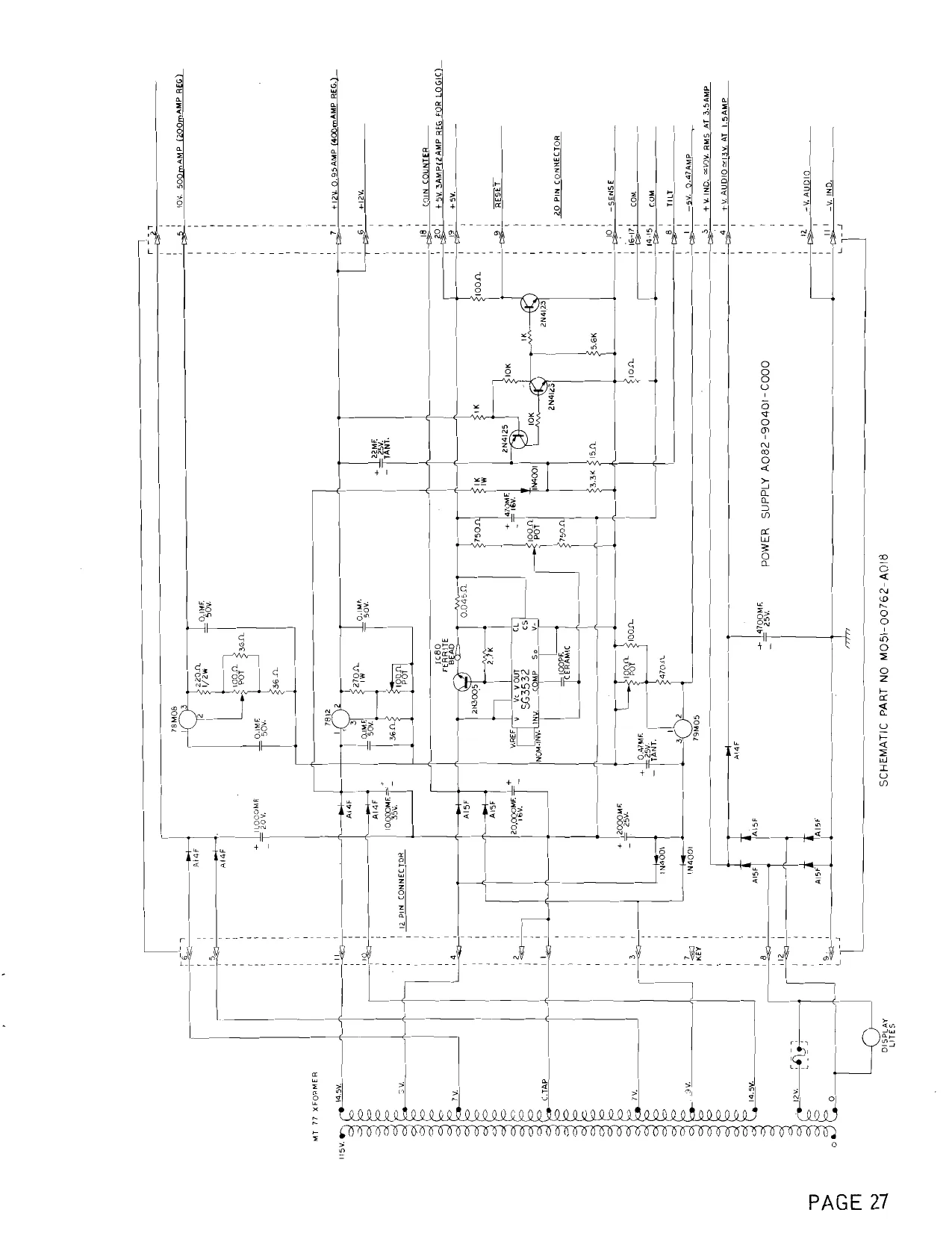
VOLTAGE CONTROL POTS: Located on Power Supply (P.C. A082-90401-C000) are preset at the factory and should not be tampered with unless the Distributor Service Department has been contacted.
MASTER VOLUME CONTROL POT: Located on Audio board (P.C. A084-90900-C762) controls the volume of all sounds and may be varied as desired by rotating pot shaft,
LINE VOLTAGE SAFETY SWITCH: A line voltage safety switch has been provided for your protection. {t is located on the right rear side of the cabinet in the back door area, When the back door is removed, it opens the circuit to the line voltage. To restore power (when servicing), pull switch fully out.
COIN, TIME AND EXTENDED PLAY ADJUSTMENT SWITCHES: Located on Mother Board (P.C. A082-90004-C000) and may he adjusted as indicated on separate instruction card in back box area.
TO ADJUST ACCELERATOR PEDAL ENCODER: 1, Place adjustment switches 6, 7 and 8 located on Mother Board (P.C. A082-90004-C000) in position indicated on instruction card in back box area.
- Loosen set screws on Accelerator Encoder gear.
- Rotate Encoder shaft until time display reads “02”. 4, — Tighten set screws on Accelerator Encoder gear.
- Place switches 6, 7 and 8 in Game Mode as indicated on instruction card in back box area.
RAM/ROM TEST:
Place adjustment switches 6, 7 and 8 located on Mother Board (P.C. A082-90004-C000) in positions indicated on instruction card in back box area, The program will begin a sequence count shown on all Score Displays, 0000, 1111, etc. to 9999. If all Rams and Roms are good, the program will continually repeat. If a Ram is bad, the program will stop and show the faulty Ram’s location in the first or second race results Score Display. Example: Ram 2 is faulty. First race results Score Display will show 0022, {f a Rom is bad, it’s location will be shown in the third or fourth race results Score Display. When test is completed, place switches 6, 7 and 8 in Game Mode as indicated on instruction card in back box area.
INSTALLATION OF SEAT ASSEMBLY:
- Remove shipping cleats located on bottom of seat assembly. Install four (4) provided leg levelers to bottam of seat assembly and level seat. Position seat assembly in front of cabinet. Slide tounge on left side of seat assembly into provided slot in cabinet. Assemble support straps on each side of cabinet and seat assembly (see sketch below) using provided cap screws and washers. Relevel seat assembly.
- Open shift assembly access door and feed shift cable into cabinet as indicated on instructions in shift assembly cavity. sPen
=
SEAT ADJUSTMENT:
To adjust seat for additional leg room:
- Loosen four (4) bolts in seat assembly support strap.
- Position seat at desired location.
- Tighten four (4) bolts in seat assembly.
TO SERVICE SCORE DISPLAY:
- Remove upper rear access door. 2, From rear, loosen two (2) screws in cross member at top of glass.
- Remove glass from front. Score display may Now be adjusted or removed.
TO REMOVE STEERING PANEL:
- Unlock and remove access panel below steering assembly.
- Unlatch two (2) clamps on sides of steering panel assembly.
- Remove steering panel for service.
HEX CAP SCREW SPLIT LOCK WASHER FLAT WASHER
SUPPORT STRAP
M051-00762-A015
ADJUSTMENT SWITCHES
COINS
SW. 1 SW. 2
| 1COIN =1PLAY | ON | ON |
| 2 COINS = 1 PLAY | OFF | ON |
| 1COIN =2PLAYS | ON | OFF |
| 2 COINS = 3 PLAYS | OFF | OFF |
TIME
Sw. 3 SW. 4
| 60 SECONDS | ON | ON |
| 70 SECONDS | OFF | ON |
| 80 SECONDS | ON | OFF |
| 90 SECONDS | OFF | OFF |
EXTENDED PLAY
SW. 5 EXTENDED PLAY = 20 SECONDS ON EXTENDED PLAY = 30 SECONDS OFF
TEST — PLAY
| Sw. 6 | Sw.7 | SW. 8 | |
| PLAY MODE | OFF | ON | ON |
| RAM/ROM TEST | OFF | ON | OFF |
ACCELERATOR ADJUSTMENT = OFF OFF OFF
M051-00762-B016
NO. 762 — SUPER SPEED RACE — PICTURE
PAGE 4 MIDWAY MFG. CO.
ony SHOMPNaOORwWNH oO NO. 762 — SUPER SPEED RACE — PICTURE
ORDER BY PART NUMBER ONLY
0762-00906-00XF 0537-00903-0023 0537-00903-0044 0629-00902-0500 0762-00905-01XF 0537-00903-0023 0537-00903-0045 -0629-00902-0500 0762-00901-0000 0017-00003-0204 0017-00102-0052 0017-00104-0072 0017-00103-0073 A090-00056-0000 0090-00002-01BK 0017-00101-0555
001 7-00003-0102 0762-00114-00XF 0762-00109-00XF 0767-00108-00XF 0762-00110-00XF 0017-00101-0088 0017-00102-0048 0017-00103-0026 0586-00036-0000 0567-00106-0000 0762-00111-00XF
0762-00116-0000 0017-00102-0026 0017-00104-0014 0017-00103-0018 A161-00002-0000 3000-17155-0000 0017-00009-0033 0603-00131-0000 0017-00003-0259 0017-00009-0450 0017-00101-0642 NAME DISPLAY PLEX — 27-7/8” x 6-1/8" IGLASS CHANNEL — 27-3/4" LG. IGLASS CHANNEL — 5” LG. (2 REQ'D.) GLASS LIFT CHANNEL — 27-7/8" LG. MAIN DISPLAY PLEX — 27-7/8” x 26-1/2” GLASS CHANNEL — 27-3/4” LG. GLASS CHANNEL — 25-3/8” LG. (2 REQ’D.) GLASS LIFT CHANNEL — 27-7/8" LG. T.V. BEZEL 25" T.V. MONITOR — COLOR 1/4-20 x 1" HEX HD. BOLT (4 REQ’D.) FLAT WASHER (4 REQ’D.) 1/4-20 TINNERMAN (4 REQ'D.) COIN DOOR ASSY. COIN DOOR FRAME #6-32 x 5/16 HEX HD. S.T.M.S. (3 REQ’D.) (MOUNTS TO DOOR FRAME) COUNTER METER (MOUNTS TO COIN DOOR)
REAR FLOOR PLATE CHAIR FLOOR PLATE #8 x 1/2 PHIL. FLAT HD. BLK.S.M.S. (18 REQ’D.-TOTAL) LEG LEVELERS (8 REQ’D.) LEG LEVELER NUTS (8 REOQ’D.) ON-OFF SWITCH
(NOT SHOWN LIST C.R.T. CABINET BRACE 1/4-20 x 2” CARRIAGE BOLTS (4 REQ’D.) 1/4 PERIPHERY WASHER (4 REQ’D.) 1/4-20 HEX NUT (4 REQ'’D.) DAG SPRING ASSY. GROUND STRAP BASSICK CLAMP (2 REQ’D.)
SPEAKER GRILL — BLACK #8-32 x 1-1/2 CARRIAGE BOLTS (4 REQ'D.) MIOWAY MFG. CO. A BALLY COMPANY
NO. 762 — SUPER SPEED RACE ~ PICTURE
ORDER BY PART NUMBER ONLY [ITEM| PART N& DESCRIPTION A762-00018-0000 jNAME DISPLAY INSERT ASSY. 0017-00031-0040 |LAMP SOCKET (5 REQ’D.) 0017-00003-0219 |LAMP — 14 V. (5 REQ’D.) A762-00017-0000 /GAME OVER INSERT ASSY. 0017-00031-0040 {LAMP SOCKET (3 REQ’D.) 0017-00003-0219 |LAMP—14V. 0017-00003-0226 |LAMP —6V. (2 REQ’D.)
MIDWAY MFG. CO. PAGE 6 A BALLY COMPANY
NOTES
This space is provided for personal notes
NO. 762 — SUPER SPEED RACE ~ GEAR SHIFT ASSY.
® — @©——
MIDWAY MFG. CO. PAGE 8 A BALLY COMPANY
NO. 762 — SUPER SPEED RACE — GEAR SHIFT ASSY.
ORDER BY PART NUMBER ONLY
0017-00009-0386 | KNOB — PHENOLIC BALL 0017-00102-0019 |CARRIAGE BOLTS 1/4-20 x 1-1/2 (4 REQ'D.) 0591-00902-0000 j|SLIDE 0017-00102-0065 (5/16 x 18 x 3/4" LONG SOCKET HD. CAP SCREW (2) 0017-00101-0510 |#4-40 x 1/2 PAN HO: M.S. (2 REQ’D.) 0017-00032-0006 |MICRO SWITCH 0588-00911-0000 {INSULATOR 0610-00123-0000 |SWITCH MOUNTING BRACKET 0610-00001-0000 |CONTROL HOUSING WELDING ASSY. 0544-00907-0000 {RUBBER BUMPER (2 REQ’D.) 0017-00042-0021 |NYLINER (2 REQ’D.) 0017-00101-0598 }#8-32 x 5/16 HEX HD. S.T. M.S. (4 REQ’D.) 0017-00101-0593 [#8-32 x 1/4 PAN HD. M.S. SEMS (7 REQ’D.) 0591-00127-0000 = |“U" BRACKET 0610-00102-0000 |REARING SUPPORT PLATE 0610-00009-0000 {BRACKET & PLATE ASSY. 0017-00104-0014 + |PERIPHERY WASHER (4 REQ’D.) 0017-00103-0018 | 1/4-20 HEX NUT (4 REQ’D.) 0591-00702-0000 {SPRING ROLLER 0017-00100-0015 | “E” RING 0610-00703-0000 {GEAR SHIFT ROD 0610-00704-0000 {PIVOT BUSHING 0017-00101-0720 = { #10-32 x 3/4 LOCKING SOCKET CAP SCREW 0010-00227-0000 |TORSION SPRING
MIDWAY MFG. CO. A BALLY COMPANY PAGE 9
AVSWASSY 1V0dd HOLVYITIIIV — JIVE G44dS HAdNS — 292 “ON
MIDWAY MFG. CO. ABALLY COMPANY
oonroanoFrwnr— NO. 762 - SUPER SPEED RACE - ACCELERATOR PEDAL ASSEMBLY
ORDER BY PART NUMBER ONLY em] part Ne | CDESCRIPTION, A762-00001-00XF A762-00002-0000 A082-91101-B000
0583-00723-0000 0017-00100-0050 0017-00101-0308 0017-00101-0785 0653-00734-0000 A762-00003-0000 0010-00228-0000 0017-00100-0031 0011-00100-06XF 0017-00103-0011 0017-00101-0769 0017-00101-0728 ACCELERATOR PEDAL & HINGE ASSY. MOUNTING BRACKET ASSY. SHAFT ANGLE ENCODER SWITCH ARDWARE FOR ITEM NO. 3 16 TOOTH GEAR “E" RING #8-32 x 3/16 SOCKET SET SCREW (2 REQ'D.) 1/4-20 x 1/4 SLT. PAN HD. EXT. S.T.M.S. STOP — POT LIMIT GEAR & LEVER ASSY. SPRING “E" RING POST — PIVOT #10-32 LOCK NUT #10 x 3/4 SLT. HEX HD. W/WASH. S.T.M.S. (3 REQ'D.) #10 x 1/2 SLT. HEX HD. W/WASH. S.T.M.S. (2 REQ'D.)
MIDWAY MFG. CO. A BALLY COMPANY PAGE 11
NO. 762 — SUPER SPEED RACE — STEERING WHEEL ASSEMBLY
MIDWAY MFG. CO.
NO. 762 — SUPER SPEED RACE — STEERING WHEEL ASSEMBLY
ORDER BY PART NUMBER ONLY [iTEM| PART N2 DESCRIPTION
A762-00012-0000 |STEERING WHEEL & SHAFT ASSEMBLY 0610-00111-0000 | NYLON WASHER — 29/32 x 1-1/2 x 1/16 0610-00016-0000 | FRONT MOUNTING PLATE ASSY. 0624-00113-0000 |MAIN MOUNTING BRKT. 0017-00101-0555 |#6 x 5/16 HEX HD. S.T.S. (2 REQ'D.) 0610-00007-0000 | BRKT. & POST SUB ASSY. 0017-00102-0019 } 1/4-20 x 1-1/2 CARRIAGE BOLT (4 REQ'D.) 0017-00104-0005 41/4 SPLIT LOCK WASHER (4 REQ'D.) 0017-00103-0018 | 1/4-20 HEX NUT (4 REQ’D.) 0017-00042-0168 |NYLINER 0017-00104-0080 |STEEL WASHER — 3/4 x 1-1/4 x 1/16 0017-00100-0109 | )"E” — RING 0591-00105-0100 j|POT LOCATOR A082-91101-B000 {ANGLE ENCODER SWITCH ASSY. HARDWARE FOR ITEM NO. 14 #8-32 x 1/4 SET SCREW (2 REQ'D.) Connon Pfwnr =
0017-00101-0309
MIOWAY MFG. CO. A BALLY COMPANY PAGE 13
NO. 762 — SUPER SPEED RACE — FRONT DOOR ASSY.
° od cz 6 oui ag ZRG Sax uw < s25 n SE Ze got >See ote t2a5 a o=<st0 22>>
NO. 762 — SUPER SPEED RACE — FRONT DOOR ASSY.
ORDER BY PART NUMBER ONLY item] part Ne | SCRIPTION, 0090-00902-0000 0090-00902-0100
0017-00101-0552 0090-00117-03XF 0090-00906-0000 0010-00007-0000 0090-0001 3-0200 0017-00005-0050 0090-00002-02BR 0017-00005-0041 0090-00901-0000 0090-00126-01XF 0017-00101-0528 0090-00903-0040 0090-00143-0000 0017-00104-0002 0017-00007-0019 0017-00103-0005 0090-00010-0000 0017-00100-0018 0090-00131-0000 0090-00104-0000 0017-00101-0598 0010-00181-0100 0090-00129-00XF 0010-00134-0000 0090-00008-0000 0093-00155-00XF 0017-00100-0012 0093-00151-00XF 0090-00005-0000 0017-00101-0555 0017-00005-0039 0010-00557-2500 0017-00007-0132 0017-00101-0507 0090-00128-00XF DRESS PLATE DRESS PLATE (W/O PRESS BUTTON TO START GAME) #6-32 x 1/4 CARRIAGE BOLT (2) COIN ENTRY PLATE (25¢) PLASTIC START BUTTON COMPRESSION SPRING DOOR ASSY. DOUBLE ENTRY DOOR LOCK & KEY WITH SCREW & NUT DOUBLE DOOR FRAME 421 N.S. CAM DOOR SWITCH SWITCH BACKUP PLATE #5-40 x 3/4" LNG. MS. 25¢ WINDOW COIN PLEX RETAINER SPLIT LOCK WASHER KEY HOOK #6-32 HEX NUT SW. PLATE & OILLITE ASSY. “E" RING SWITCH TOP & BTM. COIN CHUT W/BRKT. ASSY.
PIVOT POST SPRING ACCEPTOR FRAME ASSY. REJECTOR LEVER “E" RING COIN GUIDE MTG. BRACKET COIN GUIDE ASSY. #6-32 x 5/16 SCREW COIN SWITCH TRIP WIRE PUSH-ON RING (BIK) #4-36 x 3/4 SCREW SWITCH BRKT. — DOOR TILT
MIDWAY MFG. CO. A BALLY COMPANY
NO. 762 — SUPER SPEED RACE — TRANSFORMER BOARD ASSY.
NO. 762 — SUPER SPEED RACE — TRANSFORMER BOARD ASSY.
ORDER BY PART NUMBER ONLY fwem[ PART Ne | ______—_DEScRIPTION _——=*d MT00-00077-0000 0017-00101-0017 001 7-00101-0637 0017-00103-0008 0720-00001-0200 0017-00003-0103 0017-00003-0006 0017-00101-0018 0017-00003-0064 TRANSFORMER — UNIVERSAL #6-1/2 SLT. HEX HD. WD. SCR. (2 REQ’D.) #8-32 x 1” CARRIAGE BOLT (2 REQ’D.) WITH #8-32 HEX NUT (2 REQ’D.) - 2 POSITION FUSE BLOCK FUSE 1 AMP FUSE 3 AMP -1#6 x 3/4 SLT. HEX HD. SCREW (5 REQ'D.) 16 FT. LINE CORD — NOT SHOWN
MIDWAY MFG. CO. A BALLY COMPANY
NO. 762 — SUPER SPEED RACE — OPEN BACK VIEW
MIDWAY MFG. CO.
PAGE 18 A BALLY COMPANY
NO. 762 — SUPER SPEED RACE — OPEN BACK VIEW ORDER BY PART NUMBER ONLY itim[ pant Ne | _____beseniprion +d 0017-00003-0204 |25" T.V. MONITOR — COLOR A082-90004-B762 A084-90704-C762 A084-90900-C762 A082-90401-C000 A762-00001-00XF A762-00017-0000 |GAME OVER INSERT ASSY.
MENA ae” oe. PAGE 19
NO. 762 — SUPER SPEED RACE — ADDITIONAL PARTS LIST ORDER BY PART NUMBER ONLY jimem] part N@ | CESCRIPTION, A762-00016-0000 |BACK DOOR ASSY. A097-00001-0000 | LOCK ASSY. (1 BACK DOOR, 1 ACCESS DOOR) 0762-00903-0000 {PROTECTIVE BUBBLE 0017-00101-0628 | #8-32 x 3/4 CARRIAGE BOLTS (4 REQ’D.) 0017-00101-0619 | #8-32 x 1/2 CARRIAGE BOLTS (2 REQ’D.) 0017-00104-0021 #8 BRASS WASHER 7/16 x 3/16 x 1/32 (6 REQ'D.) 0017-00103-0061 |#8-32 HEX LOCKNUT SEMS. (6 REQ’D.) A627-00003-0000 {CASH BOX ASSY. A762-00013-0000 |CASH BOX COVER ASSY. A625-00024-0000 | CASH BOX GUIDE BRKT. ASSY. 0625-00117-0000 | CASH BOX SIDE CHANNEL 0017-00101-0628 | #8-32 x 3/4 CARRIAGE BOLTS (4 REQ’D.) 0017-00103-0061 | #8-32 HEX NUT SEMS. (4 REQ’D.) 0017-00104-0022 #8 STL. WASHER (4 REQ’D.) 0762-00900-0000 |HINGE — GEAR SHIFT PANEL 0017-00101-0639 | #8-32 x 1-1/4 CARRIAGE BOLTS (4 REQ’D.) 0017-00103-0061 |#8-32 HEX NUT SEMS. (4 REQ’D.) 0017-00003-0225 + |CHEAT INTERLOCK SW. 0625-00133-00B0 |MOUNTING BRKT. — INTERLOCK SW. A775-00013-0000 | FAN ASSY. 0618-00117-00ZN |VENT GRILL (2 REQ’D.) A082-90004-B762 |MOTHER BOARD ASSY. A084-90704-€762 |GAME BOARD ASSY. A082-90401-C000 | POWER SUPPLY BOARD ASSY. A084-90900-C762 |AUDIO BOARD ASSY. A084-01335-C762 |DISPLAY DRIVER P.C. ASSY. 0762-00115-0000 +|READ OUT SUPPORT MTG. BRKT. 0624-00902-0100 |P.C. BRKT. SUPPORT — 12 IN. (4 REQ’D.) 0624-00902-0300 + |P.C. BRKT. SUPPORT — 2-1/2 IN. (6 REQ’D.) 0624-00902-0500 + |P.C. BRKT. SUPPORT — 6 IN. 0017-00101-0017 =| #6 x 1/2 HEX HD. WD. SCREW (20 REQ'D.) 0017-00104-0027_ | FLAT WASHER — 3/4 x 3/16 x 1/16 (20 REQ’D.). 0017-00009-0419 |PIN EXTRACTOR TOOL (PIN POPPER) (MOLAX JACKS ONLY)
PAGE 20 MRM vem CO.
ace 7 pm connEcTOR scone orsmav § : H & a POWER SUPPLY PC: AOB2-90401-C000
BY cl GAME LOGIC BOARD, PC.A084-90704 C762 lac hete sopb0: crea 25 Pim connecron MOTHER BOARD PC.AQ82-90004-B000 WIRING SCHEMATIC PART NO. MOSI-00762-A002 FRANKLIN PARK, HL. 608! 10750 W GRAND AVE, “SUPER SPEED RACE" MOBY MEG. CO. SS Bethe
This page reads as a drawing: its text was drawn rather than typeset, and comes out in fragments. See the original scan.
i
Al eee (88 tye ala af]
NOTES
This space is provided for personal notes
NOTES
This space is provided for personal notes
This page reads as a drawing: its text was drawn rather than typeset, and comes out in fragments. See the original scan.
This page is a drawing, shown as the original scan.
| : | 7 | wma | HEBHE H |
wm [xem] z 5 H Fi 4
| = | pve | ebstbe |
; ;
2081 @SN . - eebe jacooen7n
| OLE | 7 | B |
: BRERE x epsibe 2682 GSN EI 4 fl Fi o | |
| a|f L8) | : | * | 3 |
a fscooen ant wsig £ a A | H e
| zege aSN | | 5) | 3 |
fe acoomind 2 -_{s S
| | LB | - | A | | | ra |
orl z UsiStwe 2884 aSN " gpa
» [2 ecistbe ; REE 2982 BSN
- * $
| . | 90re | gore | s |
fl 5 Fo g é bs 2 a é Suive sss:
zee. @SN
feria}
[xno
i
This page reads as a drawing: its text was drawn rather than typeset, and comes out in fragments. See the original scan.
2929-00606- vEOV 39K
62K Qume I et 1OOV..
| OaMe | 39K | MYLAR | |
| 7 MYLAI | 39K | 4.7ME, | lO MF, |
Ve -)16V.
| 2 | 120K | BO OR |
z 240K Lis") Pert LM3900 33M Hic OME
| o | _ | coo] an |
7 (00K M K_]
| 3 | LM3900 | oo] |
D 220K wo 220 3 10K {
| nm | S | TOK |
2 IDEIES
| Dp | =j | LOME | “™~ |
> INSTA] 16V.4 — 5
| a | Ss | SAN x |
m Fa D a Pad fy Cc BD is} i 022M
| i | wy coe —— | Weak |
| B | Cin) | MC |
g 20K Panto 340) D + -)16W.,
| 2 | [10K] | TANT. [700L, | rook |
1OK
| co4ol6 | [are] | mas | |
= [ OK INSI4 ozame on
| 1K | Cx) | SGOKIWYLA Te |
60K
| a OK | 74174 | 27m] | TOOK |
| OK | 47M | TOK | |
| (a70K | = | 560K | ETO] |
1K
| i | . | 150K |
| = | 74174 | LM3900 (270K) |
=a 270K
| 470K | EI | 470K ] |
ing14 |
| 1K | x] | cp4o1g | CiooK |
| 360K | INSTS | ¢ 9 |
| TOK | (roe | ~ |
l CD4016 LM3900
2.2MF. ara
- TAN
i - >I OME. 16 V. TANT,
% INDICATES O.IMF SOV, AXIAL LEAD CERAMIC CAR
COMPONENT LAYOUT PART NO.MOS5I-00762- A004
NOTES
This space is provided for personal notes
This page carries no recoverable text. It is a drawing or a photograph. See the original scan.
Chip Number
7400 7402 7404 7406 7407 7408 7410 7420 7421 7425 7430 7432 7474 7486 7427 74107 74154 74157 74161 74174 7A175 74191 74367 74368 TIP110 14.318 2716 SUPER SPEED RACE
Game Logic A084-90704-C762
Function
Quad 2 input nand Quad 2 input nor Hex inverter Buffer (inverting) Buffer Qud 2 input and Triple 3 input nand Duai 4 input nand Dual 4 input and Dual 4 input nor with strobe 8 input nand Quad 2 input or Dual “D" flip-flop Quad 2 input exclusive or Triple 3 input nor Dual “JK” flip-flop 4 line to 16 line decoder Quad 2 line to 1 line selector 4 bit counter Hex “D” flip-flop Quad “D” flip-flop Up-down counter Hex Bus Driver Hex Bus Driver (inverting) NPN transistor Crystal 16K Prom
Chip Number
LM3900 4016 MC3340 74174 SUPER SPEED RACE
Audio Board A084-90900-C:
Function
Quad op. amp. Quad switch Atenuator Hex “'D" flip-flop
SUPER SPEED RACE
Display Board A084-91335-C762
Chip Number Function
7406 Buffer (inverting) 7447 BCD to 7 segment decoder 7448 BCD to 7 segment decoder 7489 64 bit Ram 7493 4 bit counter 74L8138 3 to 8 line decoder 74LS157 Quad multiplexer 74175 Quad “D” flip-flop 555 Timer ULN2003B Transistor driver pack DL528 LED display (time) NSB7882 LED display (score) D44E1 NPN transistor
280 COMPACT MOTHER BOARD
Chip Number Function
7400 Quad 2 input Nand gate 7404 Hex inverter 7427 Triple 3 input Nor gate 7493 4 Bit counter 74LS138 3 to 8 Line decoder 741$ 139 3 to 8 Line decoder 74161 4 Bit counter 74367 Hex bus driver buffer 4006 18 Bit shift register 4030 Quad Ex. Or. 6810 128 X 8 Bit static RAM 2716 PROM 16K 9316 ROM 16K z80 CPU 8216 Bi-directional driver LM339 Voltage comparitar LM377 Amplifier 555 Timer
Additional Devices:
TIP 110 Transistor (NPN) 19,988 Crystal Ls Low schottky
“wiper Migr yew
| ee] | pea | = | rs. | Sw | BR Fa mee I | ) |
| 2 Baers | s gee- | fey" | Se | ca | & Sass | SCHEMATIC DRAWINGS. |
| ee See | eee | 2 re | z | 52 eae | ELECTROHOME | |
| @ vais | = 22 Sa | = See | San | ee | 25 INCH COLOR MONITOR | |
| oo | S Siuey | = Eee | = sacess | = | ) | MODEL Go2 |
| = re | 2 Se | Sl eee | peace | — | ||
| ey enced | 3 Sa | ipa eea wc | BE ae | Hexcreer eee nape | ||
| Peet toed | ea | Ser eee | Es Powe | : | Heeger |