Asteroids Deluxe Cocktail DP-174-1st-02A
Asteroids Deluxe (rev 3) (Atari, 1980) · Drawing Package · 1 pages · original scan
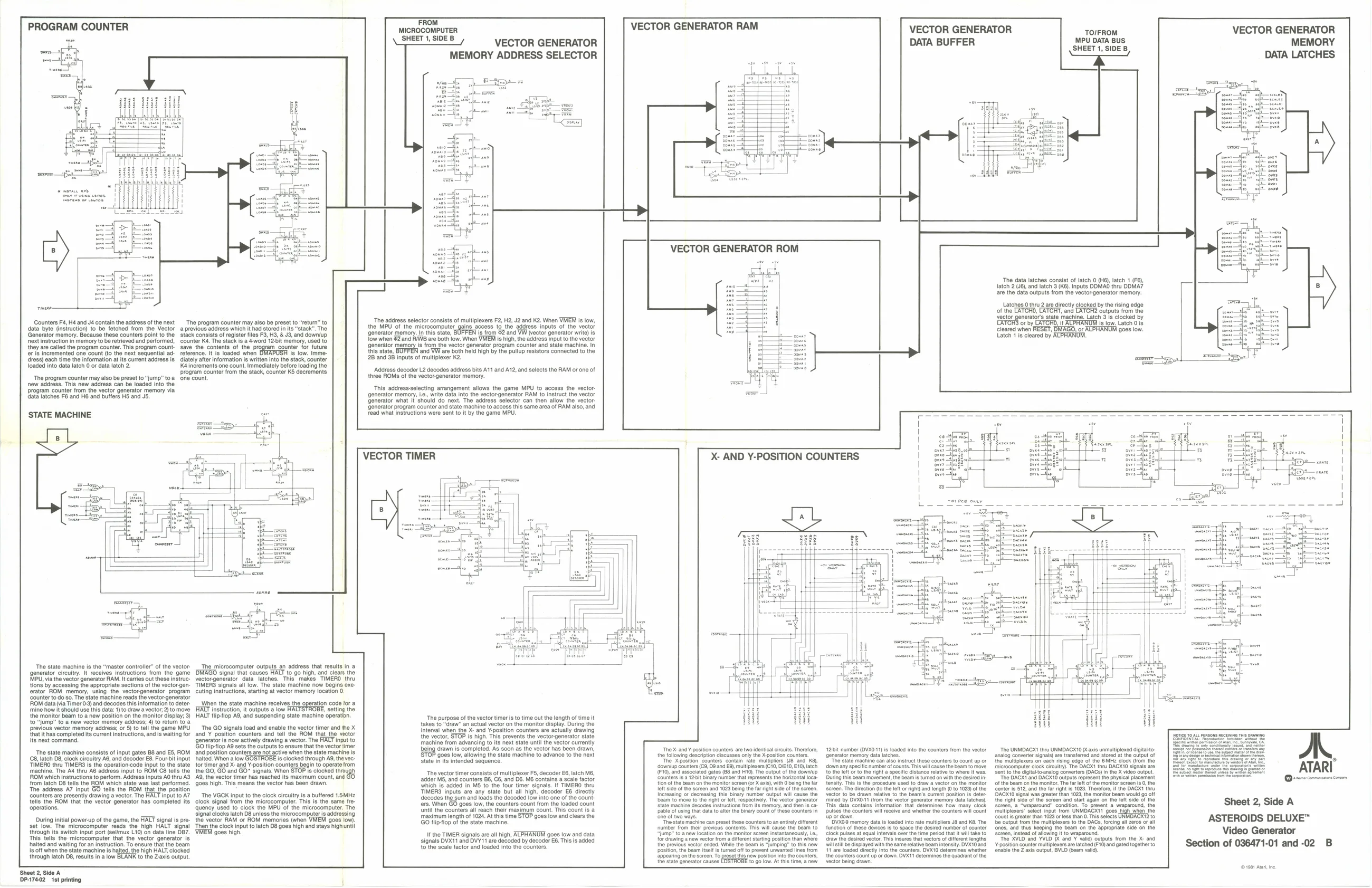
PROGRAM COUNTER
‘next instruction in memory to be retrieved and performed, they are called the program counter. This program cour
loaded into data latch 0 or data latch 2.
‘The program counter may also be preset to “jump” t
new address. This new address can be loaded into the ‘program counter from the vector generator memory via data latches F8 and H6 and buffers HS and JS,
‘STATE MACHINE Counters F4, H4 and J4 contain the address of the next The program counter may also be preset to “return” to data byte (insiruction) to be fetched from the Vector a previous address which it had stored in its "stack". The Generator memory. Because these counters point fo the sack consits of else hes F3, HS, £18, and downlyp counter save 1 er is incremented one count (to the next sequential ad- reference. itis loaded when <dress) each time the information at its current address is diately after information is written into the stack, counter
ka increments one count. Immediately before loading the
program counter from the stack, counter KS decrements. fone count.
stack is a 4word 12Bit memory, used 10
3s of tI ram counter for future is low. Imme- ‘ont
Fead whi FROM MICROCOMPUTER SHEET 1, SIDE B
VECTOR GENERATOR
MEMORY ADDRESS SELECTOR
‘The address selector consists of multiplexers F2, H2, J2 and K2. When VMEM is low, the MPU of the microcomputer gains access to the address inputs of the vector generator memory. In this state, fow when @2 and RWB are both low. When VMEM Is high, the address input to the vector generator mem: this state, 2B and 38 inputs of multiplexer K2. is from @2 and VW (vector generator write) is Is from the vector generator program counter and state machine. In and VW are both held high by the pullup resistors connected to the
‘Address decoder L2 decodes address bits A11 and A12, and selects the RAM or one of three ROMs of the vector generator memory. This address-selecting arrangement allows the game MPU to access the vector: generator memory, Le., write data into the vectorgenerator RAM to instruct Generator what it should do next. The address selector can then allow the vector {Generator program counter and state machine to access this same area of RAM also, and instructions were sent to it by the game MPU. VECTOR GENERATOR RAM
VECTOR GENERATOR ROM DATA BUFFER
TO/FROM MPU DATA BUS SHEET 1, SIDE B
VECTOR TIMER
I
‘The state machine is the “master controler” of the vector. ‘generator circuitry. It receives instructions from the game MPU, via the vector generator RAM. It carries out these instructions by accessing the appropriate sections of the vector-generator ROM memory, using the vector-generator program ‘counter to do $0. The state machine reads the vector-generator ROM data (via Timer 0-3) and decodes this information to d ‘mine how it should use this data: 1) to draw a vector, 2) to move ‘the monitor beam to a new position on the monitor display; 3) to “Jump” to a new vector memory address; 4) to return to ‘previous vector memory address; or 5) to tell the game MPU that it has completed its current instructions, and is waiting for Its next command,
‘The state machine consists of input gates B8 and ES, ROM 68, latch 08, clock circuitry A6, and decoder €8. Four-bit input TIMERO thru TIMERG is the operation-code input to the state ‘machine. The A4 thru AB address input to ROM C8 tells the ROM which instructions to perform. Address inputs AO thru AS {om latch D8 tells the ROM which state was last performed. ‘The address A7 input GO tells the ROM that the position counters are presently drawing a vector. The HALT input to A7 tells the ROM that the vector generator has completed its ‘operations. During inital power-up ofthe game, the FACT signal is pre: set low. The microcomputer reads the high HALT signal {rough its switch input port (selimux L10) on data line OB. ‘This tels the microcomputer that the vector generator is halted and waiting for an Instruction. To ensure thatthe beam is off when the state machine is hated, the high HALT, clocked through latch D8, results in a low BLANK to the Z-axis output.
‘Sheet 2, Side A DP-17402 1st printing ‘The microcomputer outputs. an address that results in a DMAGO signal that causes HALT to go high, and clears the vectorgenerator data latches. This makes TIMERO thru TIMERS signals all low. The state machine now begins exe ccuting instructions, starting at vector memory location 0,
‘When the state machine receives the operation code ACT instruction, iroutputs alow FALTSTROBE, sting the HALT flipflop AS, and suspending state machine operation.
The GO signals toad and enable the vector timer and fhe X and'Y positon counters and fell the ROM that the vector enerator is now actively drawing a vector. The HALT Input to So tiptop Ad sets the outputs to ensure thatthe vector mer and position counters are not active when the tate machine is {ortimer and Scand ¥ posiion counters begin opeate ron tor timer and X-and ¥-positon counters begin to operate rom the Go, G6 and'GO” signal When STOP s lostedtnaugh 19, the vector timer has reached lis maximum count, and 08s high. This means the vector has been drawn.
‘The VGCK input to the clock circuitry Is a buffered 1.5MHz ‘clock signal from the microcomputer. This is the same fre- ‘quency used to clock the MPU of the microcomputer. The Signal clocks latch D8 unless the microcomputer is addressing the vector RAM or ROM memories (when VMEM goes low) Then he clock input fo latch D8 goes high an stays highunt ‘9088 hig} ‘The purpose of the vector timer is to time out the length of time it 10 “draw” an actual vector on the monitor display. During the Interval when the X- and ¥position counters are actually drawing the vector, STOP is high. This prevents the vectorgenerator state ‘machine from advancing to its next state until the vector currently ing drawn is completed. As soon as the vector has been drawn, {9008 low, allowing the state machine to advance to the next state in its intended sequence.
The vector timer consists of multiplexer FS, decoder E6, latch MB, adder M5, and counters B6, C6, and Dé, M6 contains a scale factor Which is ‘added in M5 to the four timer signals. It TIMERO thru TIMERS inputs are any state but all high, decoder E6 directly decodes the sum and loads the decoded low into one of the count fers. When GO goes low, the counters count from the loaded count ‘ntl the counters all reach thelr maximum count. This count is a ‘maximum length of 1024. At this time STOP goes low and clears the GO fliptiop of the state machine.
If the TIMER signals are all high, ACPHANUM goes low and data signals DVX11 and DVY11 are decoded by decoder E6. This is added to the scale factor and loaded into the counter X- AND Y-POSITION COUNTERS ‘The data latches consist of latch 0 (H6), latch 1 (F8), latch 2 V6), and latch 3 (K8) Inputs DDMAG thru DDMA7 are the data outputs from the vector generator memory. Latches othru 2 are directly clocked by the rising edge of the LATCH, CATCH, and ‘outputs from the vector generators state machine. Latch 31s clocked by ‘or by it is ow. Latch 018 ‘cleared when RESET, DMAGO, or ALPHANUM goes low. Latch 1 is cleared by ACPHANUM.
MEMORY DATA LATCHES
‘The X-and ¥position counters are two identical circuits. Therefore, the following description discusses only the X-pastion counters. ‘the Xpostion counters contain rate multipliers (JB and 8), <downiup counters (63, 03 and E9, multiplexers (C10, OIE10, E10) latch (10, and associated ‘gates (88 ana H10). The output ofthe downlup 1 12bIt binary number that represents the horizontal loca: 1 beam on the manitor screen (oF X axis with O being the far Tet side of the screen and 1023 being the fr right sid of the screen. Increasing or decreasing this binary number output wll eause the ‘beam to move to the right o let, respoct ‘State machine decades instructions trom able of using that data o alter the Binary count ofthese counters In ‘ne of two ways “Te state machine can preset these counters to an entirely itferent ‘number from thelr previous contents. This wil cause the beam to jump” toa new loeation on the moniter sereeninstantangousy, Le, {or drawing a now vector trom a diferent starting position than where the previous vector ened. While the beam is “jumping” to thie new position, the beam iset i tuned of o prevent unwanted lines from ‘Sppearing onthe screen. To preset thisnew postion Into the counters, the state generator causes 10190 Jow. At his time, a now ‘12.it number (OVX0-1) i loaded into the counters trom the vector generator memory data latches. "The state machine can also Instruct these counters to count up of specific number of counts. This wil eause the beam to move to tho let orto the right a speci distance relative to where I was. During this beam movement, the beam is turned on with the desi intensity. This isthe procedure used to draw a vector on the monitor screen. The direction (othe lft or right) and longi (010 1023 of the ‘ctor to be drawn relative to tho beame eurent position is Geter ‘mined by DVXOT (rom the vector generator memory data latches) TTis- data contains information that determines how many clock pulses the counters will receive and whether the counters wil count {0 oF down. DVX09 momory data Is loaded into rate multiplies J8 and KB. The function of these devices is to space the desired nuriber of counter clock pulses at equal intervals ovr the ime period that it wil take to ‘raw the desired vector. This insures that vectors of aferent lengths ‘Wilt be cgplayed win the same relative beam intensity. DVXIOane 11 are loaded aiectly Into te counters. OVXTO doteemiogs whether {he counters count up or down. DVKI1 determines the quadrant o he vector being drawn. ‘The UNMDAGX! thru UNMDACX10 (Xaxis unmultiplexeddigtalto ‘analog convertor signal) are transferred and stored atthe output of the muliplesers on each rising edge of the GMHz clock (rom ‘microcomputer clock creulty). The DAGXT thru DACXTO signals ‘Sent to the digitaltoanalog converters (ACs) inthe X video output “The DAGXtand DAGXIO outputs represent the physical placement ‘ofthe beam on the monitor. The far lot ofthe monitor screen Is. the enter is 512, andthe far righ is 1023. Therefore, if the DACXI tha ‘DACKIO signal was greater than 1023, te monitor beam would go oft {the ight ‘side of the screen and start again on the taf side of the ‘eroen, a “wraparound” condition. To prevent a wraparound, the ‘ultiplexers” select input from UNMDAGX'T goes, high when the Counts greater than 1023 or less than 0. This selects Tato be output from the multiplexers to the DACs, forcing all zeros or all ‘ones, and thus Keeping the beam on the appropriate side on the ‘Seroen, instead of allowing it to wraparound, ‘The XVLD and YVLD and’ vali) outputs from the X- and ‘postion counter multiplexers are latched (10) and gated topether to enable the 2 axis output, BVLO (Dear vali Sheet 2, Side A ASTEROIDS DELUXE™ Video Generator Section of 036471-01 and -02 B
©1961 Aa, ne