Galaxian Troubleshooting Guide Part 2
Galaxian (Namco set 1) (Namco, 1979) · Troubleshooting · 37 pages · 11 sections · original scan
~ MIDWAY’S
TROUBLE SHOOTING LOGIC BOARD
PART II
2? MIDWAY MFG. Co. ALY COMPANY PHONE 10750 WEST GRAND AVENUE
PHONE TOLL FREE
(312) 451-1360 FRANKLIN PARK, ILLINOIS 60131 g99 393.7182 U.S.A.
GALAXIAN, Midway's new space wars video equally determined to annihilate him by firing game, features a full color monitor and is avait missiles. The defender must protect himself without able in a 1 or 2 player upright or cocktail table the aid of barricades. He must shoot down not only model. alien amy regulars, but also out-maneuver and destroy enemy fighter escort ships that peel off The player, controlling the Galaxian defenders of from the main body of the alien squadron at the Earth, must destroy a convoy of aliens that are random.
Score: ALIEN SHIPS’ POINTS:
| 4 or 2 player. Maximum | HIGH SCORE | Flagship: 60 points each. |
score: 999,990. |__2® 000000 150, 200, 300 and 800 bonus
High Score: points when hit while
Retained and displayed attacking.
| up to 6 digits. | 7 | Red Alien: 50 points each. |
| Defender Galax Ship: | pana | 100 bonus points for hits |
| Moves freely across bottom | Km | while attacking. |
of monitor firing missiles at . Purple Alien: 40 points aliens. . each. 80 bonus points for
| Reserve Galax Ships: | . | hits when attacking, |
Number of player-up 7 . Alien: 30 points
| remaining ships clearly | 7 | each. 60 bonus points |
indicated. when attacking. Credit Line: Alien Attacker Ships: Maximum 9 credits Double score for each ship per player. shot down. Flag: One awarded for each convoy destroyed. BONUS POINTS:
450 Points: 200 Points: 300 Points: Special 800 Points: Pees lone green cen aen For hitting lone For hitting attacking —_ For hitting attacking For destroying fighter attacking at random. — attacking flagship. _ flagship with single _ flagship with two escort and flagship. escort. escorts. (Escort ships must be hit first)
MIDWAY MFG. CO. DISTRIBUTED BY: A BALLY COMPANY 10750 West Grand Avenue Franklin Park, IL 60131 Phone: (312) 451-1360
Printed in U.S.A.
TABLE OF CONTENTS
Introduction
Assumption - Video Probe Assembly
Flow Chart
Case A-Bad Power Supply
Case B-No Video
Case C-Bad Menu
Case D-Test
Case D1-Sound
Illustrations of Problems and Possible Solutions
Appendix
IC Function List
Component Layout
Logic Terms
Logic Terms Z-80
Service Bulletins
Schematics Page No. C7 MRAA Aw =
INTRODUCTION
Midway’s new game, Galaxian, promises to be one of the hottest new games on the market
today. As with any high production product, there will be a need for servicing from time to time.
Therefore, since necessity is the mother of invention, this manual is being written to satisfy that need
and to simplify troubleshooting.
The game itself is a highly complex system, but with a few basic tools all but the most difficult
problems can be solved. This manual will show you how to track down the most common problems and
show you how to fix them. It does not in any way explain how the board works, as that could
conceivably run into volumes of text.
So use this manual to its fullest potential, GOOD LUCK!
NOTES
THIS SPACE IS PROVIDED FOR PERSONAL NOTES
ASSUMPTION
It is assumed throughout this manual that the board in question was once a working board;
that is, there are no shorts, open lines or wrong parts. However, there may be isolated cases where
such a condition occured during normal use. These conditions, although rare, will be discussed
where appropriate. It is also assumed that the service person has the following:
1)
2)
3)
1)
2)
3)
4)
1)
2)
3)
4) AVOM or facsimile
A double clip lead ie, a jumper cable
A‘‘Video Probe’’ assembled as follows
VIDEO PROBE ASSEMBLY
Use a piece of insulated stranded wire AWG 16 or smaller.
Solder a 470 ohm resistor to one end and tape the connection for insulation.
Solder a miniature clip to the other end and tape as in step 2.
Check completed video probe for solidarty.
VIDEO PROBE USE
Connect clip of video probe to R59 between R62 and ground.
Test probe by touching resistor lead on probe to + 5v.
A bright green block should be seen in the middle of the screen surrounded by a dimmer
green boarder.
Probe is now functioning and ready to use.
It should be mentioned here that the video probe, although useful in many cases, is not a
replacement for a 50Mhz oscilloscope. Whereas, it will show the presence or absence of certain signals, it will not always detect wrong signals without a little practice in identifying the wrong ones. Therefore, if possible, it is recommended that you check the signals shown here before the
’ board fails, to familiarize yourself with the proper responses to signals of your own video probe.
FLOW CHART OF TROUBLESHOOTING PROCEDURE
Bad Board
Bad
~riowre? No ce
See Pictures For Symptoms Normal Menu?
Go to Case D
Good Board
CASE A-BAD POWER SUPPLY
The power supply on the Galaxian game board is relatively simple to troubleshoot and repair.
- Disconnect the +5v jumper located next to the two A14F diodes D6 & D7.
- With the power off, check both sets of diodes with an ohm-meter for short or open
condition. If a diode is found to be faulty, replace it.
- If diodes check out, check the two 10,000uf capacitors for shorts to ground.
If the board is OK up to here, the problem is probably with the D44VM4 and the UA78GU1C.
Replace both if found to be faulty. Turn the power on and measure + 7v from one side of the jumper
to ground. If +7v is not measured, replace the 1N4736 (D8) zener diode. Reconnect the jumper and
turn on the power. The board should be functioning properly.
CASE B-NO VIDEO
In the case of no video, it is assumed that the board was once a working board, the
power supply is working, there are no stars or “‘garbage’’ on the screen
First, with the video probe previously described, check the 74LS161's located at
3A,4A,5A, and 6A. You should observe horizontal lines on the pins of 3A and 4A that become more
numerous and thinner as the probe is moved from pin 11 to pin 14 on each chip. If there are none on
3A, replace the 18 Mhz crystal and after that the 74368 at 1E. On pins 11 to 145A and 6A, you should
see vertical lines in the same fashion as 3A and, 4A. See ILLUSTRATIONS chapter.
If the lines do not appear on any of the output pins on 3A,4A,5A, & 6A cut the pin and check
with Video Probe. The lines will appear if the 74LS161 is good. If the lines are missing change the
74LS161.
If these chips are found to be OK, the next step is to check the Xor gates located at 3B, 4B, 5B,
and 6B. This is done in the same manner as the 74LS161's just discussed. Figure 1 shows the entire
section with the Xor gates on the outputs. The inputs of these chips should resemble the outputs. If
they do not, cut the pin and check the line and the pin. If the pin is OK, reconnect the first pin cut,
then cut any pin connected to that line until the line looks right again. Replace faulty part.
This page reads as a drawing: its text was drawn rather than typeset, and comes out in fragments. See the original scan.
If the problem hasn’t been remedied by this time, it may be a difficult and involved one. See
ILLUSTRATIONS of video probe data for CPU ADDRESS and DATA, and compare them with your
findings. Also, try replacing the memory board and CPU to be sure they are not the cause of the
problem.
CASE C-BAD MENU
The “MENU” in the case of Galaxian may also be called the “Shill” or “Attract” mode. That is, the
game “plays itself” to attract players. It starts with “1 UP” and “High Score” at the top with “00”
under each. “GAME OVER” appears on the lower 1/3 of the screen and “CREDIT 0” in the lower left
corner. It then prints the Galaxian’s mission and score advance table with the “CHARGER” scores
flashing. Then it plays a short game and repeats.
Many of the problems present in the game, except sound, can be observed and/or repaired in this
mode. See other sections for specific problems and solutions.
CASE D-TEST
SEE PARTS AND OPERATION INSTRUCTION MANUAL SUPPLIED WITH GAME FOR
COMPLETE TEST PROCEDURE
This section deals with the switches on the front panel and coin switches.
lf any switches (left, right, fire, etc.) fail to work or emit a game noise during test mode, procede as
follows:
- Clean contacts on faulty switch with a stiff pen eraser.
- With an ohm meter, check the wire from the switch to the game board for continuity.
- Check the corresponding resistor and .1uf capacitor for proper value.
- If the capacitor proves to be faulty, replace it.
- If there is no problem here, change the corresponding 74LS368, according to Fig. 2.
The sounds corresponding to switches are given in table 1.
TABLE 1—SOUNDS & SWITCHES
SWITCH
Left-right Alien hit Fire Missle sound
Player 1-2 start Yellow attacker hit
Coin 1-2 Coin sound
FIG. #2 SECTION SHOWING 74368s
2 SHOOT
2 RIGHT
P2 LEFT
2P START
IP START
PU RICHT
Pr err
SERVICE
Test
TABLE
SHOOT
come
coms TSS SS CSS ONS SOS SS ESO OSS SOE SASS
CASE D1-SOUND
There should be very few sound problems, but if encountered they are easy to fix using
an ohm meter and a jumper to +5v. Most often the problems will be no sound, distorted sound
and/or hum. In all cases, replace the .1uf capacitor located next to the LM 377 at 11A. If this doesn’t
clear it up, replace the LM377 and its heat sink. (.1uf capacitor C46)
All but two of the sounds can be checked in the test mode. The sounds not tested are explo-
sion and background noise (rack movement).
BAD EXPLOSION
To check the explosion in the test mode use a jumper to + 5v and touch pin 7 of IC9L. This will cause the sound to remain on until the board is reset or placed in the game mode. If no explosion
sounds, touch the anode side of D1 with the jumper. If explosion does sound, check R89 for continu-
ity. If found to be faulty, replace it. If good, replace D1. If still no explosion, place video probe on one
side of R40. “Noisy” or “dancing” green bars should be seen on the side away from pin 1 of IC7T. If
not, replace LM 324 at 7T.
BACKGROUND NOISE (RACK MOVEMENT)
The background noises can be checked individually in the test mode by touching the +5v
jumper to pin 4 of IC’s NE555 at 8R, 8S and 8T. If any one is bad or missing, replace C17, C18, or
C19 respectively. If this doesn’t work, replace faulty NE555. If all sounds are present but don’t
oscillate, replace both Q1 and Q2, GE6015 transistors.
FIRE
The fire or missle sound if missing, can usually be fixed by replacing C26, or .01uf mylar
capacitor. If not, place video probe on pin 5 of IC7T, press fire button twice rapidly and hold it in.
Check screen for faint “DANCING” lines. If they are on pin 5 and not brighter on pins 6 and 7, replace
bad LM 324.
OTHER SOUNDS
All other sounds are generated by the 1C74LS273 at 9J, the two I1C74LS161’s at 8K and 9K,
and the 1C74LS393 at 6T as seen in figure 3. Most often these will be indicated if the sounds are
‘‘jumbled.’’ There may be a ‘‘hissing’’ noise in the sound which is usually remedied by changing the
470uf capacitor, C37, next to the power supply.
OTHER SOUNDS (CON’T)
To troubleshoot the sounds generated by 9J, 8K, and 9K, check the outputs of 9J with the video
probe. When normal, an output will display a solid green biock in the middle of the screen. When a
switch is closed, it will flash off and on. This is true of all outputs from 9J.
If any one output does not flash, cut the pin and check the pin and the line. If the pin produces
a flashing box, change the corresponding IC74LS161. If not, 9J is bad and should be replaced.
Only one output is used from the 1C74LS161’s, eg pin 5. If nothing is flashing on pin 15 of 8K, check pin 15 of 9K and replace 9K if found to be faulty. When all is normal up to pin 8 of 6E, and the sound is still not good, check pins 6 and 13 of 7R. When normal, pin 6 should slightly dimm the
color when using the video probe. Pin 13 should put a solid green block on the screen for the
duration of the sound, then dim the color. If this is not the case, cut the pin and check the line. If
found to be OK, check the pin on the IC74LS259 at 9L. If the pin on 9L is OK, replace the bad 4066 at
7R. If the pin is bad, replace the bad IC74LS259 at 9L.
FIG. #3 SECTION SHOWING 74161s, 74393 & 74273
ah]
NOTES
THIS SPACE IS PROVIDED FOR PERSONAL NOTES
ILLUSTRATIONS
This chapter deals with some symptoms of bad video and shows some of the typical responses
of the video probe.
Figure 1 shows the MENU with the reset button held in. You will notice the lack of stars and “‘charger’’ point values. The missing stars are normal with the reset button held in. Since the
“‘charger’’ points flash on and off, they are missing only because the button was pushed when they
were off.
Figures 2 through 16 show the 8 basic types of data as seen by the video probe. As can be
seen in Fig. 2, 3 and 4, the VB signals start out wide and few and get thinner and more numerous as
the probe is moved from pi 12 to 14 of IC5A and IC6A. The above description applies to Figures 6, 7,
and 8, substituting HB signals with VB signals and IC3A and IC4A with IC’s:5A and 6A.
Figure 9 shows a typical output of the 1C74LS273 located at 2M. When the game is running in the shill mode, you will notice the movement of the green bars with the rack and the Galaxip.
Depending upon the output selected, the bars will be of different sizes.
Figure 10 shows a typical output of one of the outputs of the 1C74LS283’s located at 4N and
5N. As can be seen in the schematic, their outputs go to the inputs of the 1C74LS273 at 2M and are
changed to resemble the outputs shown in Fig. 9.
Figure 11 shows a typical H-Position signal. These should all look about the same but flicker at different rates.
VRAM DATA, as seen in Figure 12 will put isolated squares and rectangles on different
parts of the screen. All but the one seen on pin 12 of 3F will put green squares on the screen and
leave the background normal. Pin 12 of 3F will make the background green and put blank squares on
the screen.
BD DATA is shown in Fig. 13. These Should look similar to each other.
Figures 14 and 15 show CPU ADDRESS lines of different frequencies. You shouldn’t have to
check these very often, but it may help to see what they look like. This holds true for Fig. 16 as well.
VIDEO ILLUSTRATIONS
WE TaN Oggae
WE eRe THE GALAnInNS NISGTON: DESTROY ALTE
minway caeprt 0
Fig. 1 Normal Menu with reset Fig. 2 Normal VB as seen with Fig. 3 Normal VB as seen with button held in. the video probe on pin 12 of the video probe on pin 14 of IC6A IC6A.
Fig. 4 Normal VB as seen with Fig. 5 Normal enable of VB video probe on pin 14 of IC5A counters as seen with video probe on pin 15 of IC5A and pin 10 of IC6A.
VIDEO ILLUSTRATIONS
Fig. 6 Normal HB as seen with Fig. 7 Normal HB as seen with Fig. 8 Normal enable signal for video probe on pin 12 of IC4A. video probe on pin 14 of IC3A. HB counters as seen with video probe on pin 15 of IC3A and pin 10 of Fig. 4A.
eee Soe ten SESESECE ETS TE
Fig. 9 Normal output of Fig. 10 Normal output of 74LS273 pin 19 of IC2M. 74LS283 pin 10 of IC5N
VIDEO ILLUSTRATIONS
Fig. 11 Typical H POSI. data as Fig. 12 Typical Vram data. Fig. 13 Typical BD data. seen with the video probe.
Fig. 14 Typical CPU address Fig. 15 another type of CPU Fig. 16 Typical CPU data. signal. address.
VIDEO ILLUSTRATIONS
mown camit o
Fig. 17 Missing address on Fig. 18 Bad attack Ram 1S. Fig. 19 Bad attack Ram 1R. attack Ram. Note - the lines and distortion on divers. (27LS00)
Figure 17 shows what usually happens when an attack Ram goes bad. When the aliens dive,
there may be colored or just black lines through the attackers. When lines appear, it is a symptom of
a missing address line within the Ram. Therefore, the bad line may not appear to be bad when
viewed with the video probe.
TROUBLE SHOOTING BAD ATTACK RAMS IS DONE AS FOLLOWS:
- Connect jumper cable to +5v.
- Touch Pin 6 of each attack Ram and watch divers.
- You will notice one attacker disappears or all attackers look distorted.
- Whichever Ram makes the lines go away when touched to +5v is the defective Ram.
- If socketed, double check by pulling out suspected Ram.
- Replace if found to be faulty.
, Figures 18 and 19 also show symptoms of a bad attack Ram. They also show what happens
when the technique listed above is used for 2 of the attack Rams. See No. 3 Above.
Figure 20 shows a typical reaction to a bad output from IC4L, a 74LS273. When the attackers dive, they may turn into many different and definitely wrong characters such as parts of an
explosion, red Galaxip or numbers and letters as shown here.
Figures 21 and 22 illustrate symptoms of a bad RAM 3 (C2101 at 4F and 5F). This problem is
probably the most common one you will come across. It can be described as ‘‘Breaking Up”’ of all
movement in the rack and Galaxip. Figure 21 best shows what happens when ICSF is bad. Note the
wrong letters and the small line next to the moving alien (to the right of the ‘‘30’’). Figure 22 shows
the ‘‘Breaking Up’’ of video. This usually points to IC4F, however, both 1C2101’s can cause either
symptom.
Sometimes a bad 1C2101 is indicated if the shells from the Galaxip flicker when an attacker is in the air. Also, when a shell is fired and the ‘‘High Score’’ moves rapidly to the right.
Other symptoms of a bad RAM 3 include, parts of aliens missing, distorted aliens after warm up, flickering aliens, distorted letters, distortion on explosion and ‘‘BAD RAM 3°’ on screen. If
these RAMS are in sockets and any of these symptoms appear, replace the RAMS one at a time until
it is cleared up. If it proves not to be a bad RAM and the motion is still breaking up, use the video
probe in the following manner:
- Place probe on the outputs of the 1C74LS273 located at 2M.
- Push reset button and wait for screen to clear.
- Observe the motion and watch for any inconsistency of motion.
- When. inconsistency of motion is found, check the input for the same inconsistency.
- If the input is OK, replace the 1C74LS273.
- If the input is bad, replace the corresponding IC74LS283 at 4N or SN according to the schematic.
Figure 23 is an extreme case of bad RAM 2 ie missing pin 13 at IC 3F. Usually the board will just read, ‘‘BAD RAM 2” on the screen. If this is the case, replace 1C2114’s at 3F and 3H, or 9B & 5J.
Figure 24 shows a rare case of no sync. Proceed as follows:
- Follow the line back from R65 to pin 6 of IC6H for breaks.
- If none, clean contacts on board with a stiff pen eraser. If that doesn’t work, replace IC6H.
Figure 25 shows an input to the RAMS at 3F and 3H. It looks like fig. 9 except for the Address
visible along the bottom. It is an output from a 74LS157 multiplexer located at 3E. This IC ‘‘adds’’
the outputs from the 74LS273 at 2M and CPU ADDRESS to supply ‘‘VRA’’ Address to the 1C2114
RAMS at 3F and 3H.
Fig. 23 Bad RAM 2 Fig. 24 No SYNC
IC2F. being multiplexed at Fig. 25 Showing output data from IC5N and CPU address pin 7 IC4L. Fig. 20 Typical of bad output on bad RAM 3. Fig. 21 Typical symptom of a bad RAM 3. Fig. 22 Typical symptom of a i ; WE ARE THE GALARtANe VIDEO ILLUSTRATIONS
APPENDIX
QUICK REFERENCE OF PROBLEMS + SOLUTIONS
SYMPTOM
No Video
Aliens Break Up*
Picture Breaks Up
Galaxip, Letters Break Up
Stars Flash or are Missing
Blows Fuses
Lines in Picture (Colored or Black)
Lines through Attackers
Bad Ram 2 on Screen
Bad Rom on Screen
Tilts Itself (Resets)
Garbage on Screen
No Sound POSSIBLE SOLUTION
Power Supply
2101
2101
2101
74LS164
Power Supply
27LS00, 93411, 82516 + 27LS00, 93411, 82516 +
740245**
Rom Card
Rom Card
Rom Card
1877,.1 uf Cap. (LM 377) LOCATION
4F/5F
4F/5F
4F/5F
1A/1B
1N-1T
1N-1T
9B/5J**
7F-7L
7F-7L
7F-7L
WIA, C26
The table above shows some of the most common problems and probable trouble areas. Use this
table for quick fixes and reference to problem areas only.
- SEE ILLUSTRATIONS
+ All the same type of part located at 1N-1T with heat sinks glued on.
**74C245 is a Bi-Directional bus driver. Some boards have 2-8216’s as bus drivers. In this case, the
problem probably lies somewhere else.
GALAXIAN LOGIC BOARD
CHIP NUMBER FUNCTION
74LS00 Quad Two Input Nand 74LS02 Quad Two Input Nor
7404 Hex Inverter
74LS08 Quad Two Input And
74LS10 Triple Three Input Nand
74LS20 Dual Four Input Nand
74LS30 Eight Input Nand
74LS32 Quad Two Input Or
74LS74 Dual ‘‘D’’Flip-Flop 74LS86 Quad Two Input Exclusive Or
74LS107 Dual ‘‘JK’’ Flip-Flop
74LS138 Three to Eight Line Decoder
74LS139 Dual Two to Four Line Decoder
74LS157 Quad Two Input Multiplexer
74LS161 Four Bit Counter
74LS163 Four Bit Counter
74LS164 Eight Bit Shift Register
74LS174 Hex ‘‘D’’ Flip-Flop
74LS175 Quad’’D’’ Flip-Flop
74LS194 Eight Bit Shift Register
74LS259 Eight Bit Addressable Latch
74LS273 Octal ‘‘D’’ Flip-Flop
74LS283 Four Bit Binary Adder
74LS245 Octal Bus Transceiver
74LS366 Hex Bus Driver-Inverting 74LS367 Hex Bus Driver
74LS368 Hex Bus Driver-Inverting 74LS377 Octal ‘‘D’’ Flipflop
GALAXIAN LOGIC BOARD
CHIP NUMBER
74LS393
27LS00
2114
TMS4045
AM9124
2101-2
AM9101
8304
8216
LM324
LM377-1877
Z80
2716
1M5610-82LS123
78GUIC
ULN2075
18.432
CD4066
D44VM4 TIP-31
GE6015
MC14066
GEA15F
A14F
1N4148
IN4736A
D2316EC-9316
D2364C FUNCTION
Dual Four Bit Binary Counter
Ram
Ram
Ram
Ram
Ram
Bus Driver-Bidirectional
Quad Operational Amp
Timer
Audio Amp
CPU
Prom-16K
Prom
Voltage Regulator
Quad Buffer
X-TAL
Quad Electronic Switch
Transistor
Transistor
Quad Electronic Switch
Diode-Rectifier
Diode-Rectifier
Diode-Rectifier
Diode-Zener
16K Rom
64K Rom
’ 8 7 10
x
74LSI6¥ 7ALSI63} giBed b
ter. pease x rie ig ed .
[ora]
TALSI6I TASIG fi fag} +
ALSIE! TALSIGI ia yee Bi fced SRE
ALSOO ALSIO Pug ie)
> 7ALSO8 7 1K a) ALS273 f] ALS367|
L LSI TALIS?
K |e ALSI4 FALSIS7
J ALSO4 ALSIS7 oS
a be ALSIE7
eetpagrc Svesivd 7 abdEs” B =
Jdo1016 HY, 21012 (RE : alt 24 PIN SOCKET Beseat-r06. FETT pjseneeeense9808
I i) i L~---4
pausis7 z fas367] a masse bee
7FALSIO. Bea
7A S367] ALS367| prusaes
(woe) Gen Coo} (u0or]
a x 7am
FALSIC4| pRALS366 7ALSB6 ees }
cr E
i =
7ALSI6I 7ALSIGI fare 83048; aa basses} ©x LIEW}
= [ l RC.A0B2-91352- 8000 mo
)
Audio
Blue
Green
Red
BD
CMP SYNC
CMP BLK
COL
cs
CNTR CL
CLR
cD
Driver
D
DIP SW
FS
DI GALAXIAN
Logic Terms
PC A082-91352-B000
Address
Common line for all sounds except Explosion
Color
Color
Color
Bidirectional Data
Composite Sync
Composite Blanking
Color
Chip Select
Counter Clear
Clear
Color Data
Enable low sounds
Data
Switches on Logic Board
Frequency Select
Data In
HIT
FIRE
G
HPOS
HFLIP
LBWE
LBA
LSD
LD
MLD
MSD
MSLD
MHZ
Missile
NMION
Noise
1&0
Pitch
PGM
OBJ RAM WR
OBJ RAM RD
OBJ RAM GALAXIAN
Logic Terms
PC A082 - 91352 - BO00
Explosion Sound
Missile Sound
Gate (chip enable)
Horizontal position
Horizontal Video flip
Line Buffer write enable
Line Buffer Address
Least Significant Bit.
Load
Missile Load
Most Significant Bit
Missile Shell Load Data
Megahertz
Player’s Missile
Non Maskable interrupt on.
Sound noise for Missile and Explosion.
Input and Output
Load High Pitch Sounds
Program
Object Ram Write
Object Ram Read
Object Ram
GALAXIAN
Logic Terms
PC A082-91352-B000
RAM RD RamRead
Reset Clears Memory
RA Ram Address
RC Raw Color
RV Raw Video
RAW Raw (Data)
RVIS Raw Video Select High
RVOS Raw Video Select Low
SLD Shell Load
Sound Enable all Sounds
Shell Invader Shell
Stars Video Stars
VPL Vertical Position Load
VID Video
VRA Vertical Ram Address
VRCS Vertical Ram Chip Select
VRAM Vertical Ram Chip Select
VRAM RD Vertical Ram Read
VRAM WR Vertical Ram Write
V Blank Vertical Blanking
V SYNC Vertical Sync
H SYNC
Vv RAM CS
VOL
WE
WDR
WEN
WREQ GALAXIAN
Logic Terms
PC A082-91352-B000
Horizontal Sync
Vertical Ram Chip Select
Volume
Write Enable
Watchdog Driver
Write Enable
Write Request Write Enable
Z-80 CPU PIN DESCRIPTION
The Z-80 CPU is packaged in an industry standard 40 pin Dual In-Line Package.
The !/O pins are shown in figure 3.0-1 and the function of each is described below.
My iaREO system 2 lORO conTroL 9 Fi A
AFSH
HALT
wart cpu CONTROLS int wi
ESET cpu BUSRO soe BUS: CONTROL \ BUSAK
45V GND ADDRESS BUS
DATA BUS
2-80 PIN CONFIGURATION FIGURE 3.0-1
LOGIC TERMS 2-80 SYSTEM
ADD Address
AUDIN Audio In
BUSAK Bus Acknowledge
BUSRO Bus Request
BUZOFF External Control
B-Y Blue Minus Video
BYTE Has Four Pixels
CE Chip Select
CAS Column Address Strobe
CASEN CAS Enable
D-O Data Out
D-1 Data In
DATEN Data Enable
{or Q Input-Output Request
HD Horizontal Drive (63.5 us)
INT Interrupt Request
1&0 Input-Output Signals
LTCHDA Latch Data
LITE PEN Interrupt Control
MD Memory Data
MA Memory Address
M1 Machine Cycle One
MREQ Memory Request
MUXD Multiplex Data
MC Mirco Cycle Control
MENEN Memory Enable
NMI
OG
PX
PIXEL
RAS
RFSH
RAMSEL
RD
R-Y
SYSEN
Ss!
so
VD
VIDOT
WE
WRTCL
WR
RESET LOGIC TERMS 2-80 SYSTEM
Non Maskable Interrupt
Phi-G Clock
Monitor Picture Clock
Smallest spot on color monitor screen with information
Row Address Strobe
Refresh
Ram Select
Memory Read
Red Minus Video
System Enable
Signal In
Signal Out
Vertical Drive (16.6 MS)
Video Out
Write
Write Control
Memory Write
Normally high
an.active low
resets the Z-80
CABLE — MIDCO.
TELEX NO. 72-1596
MIDWAY MFG. co. PHONE: AREA CODE 312 451-1360 ‘A BALLY COMPANY CHICAGO PHONE: 992-2250
10750 W. GRAND AVENUE e FRANKLIN PARK, ILL. 60131
SERVICE BULLETIN
Game: Galaxian (As of Serial No. 11,500)
Subject: Rom program identification (3rd Program)
eeeverererrrrrrreeee Te CSCC Ce Tre ttt te ttttrrireriri irri reese es irri rire,
- The 3rd program change has new Bonus values. (see Figure #1)
- New program identification (Game, Location and Program)
M866 - U - 0982 M866 - V - 09S2 M866 - W - 09S2 M866 - Y - 09S2 M866 - Z - 09S2
- The 1st program version 09SO and 2nd program version 09S1 can not mix with 3rd program 0982.
- The 1st and 2nd program has 2716 Proms and also 2716 Proms mixed with 9316 Roms.
- If additional clarification is needed please call the service department.
- New Program Bonus Values are as follows (Figure #1)
sw 3 sw 4
| Bonus Galaxip at 7,000 pts. | OFF | ON |
| Bonus Galaxip at 10,000 pts. | ON | OFF |
| Bonus Galaxip at 12,000 pts. | OFF | ON |
| Bonus Galaxip at 20,000 pts. | ON | OFF |
CABLE — MIDCO.
TELEX NO. 72-1596
PHONE: AREA CODE 312 451-1360 MIDWAY MFG. CO. A BALLY COMPANY CHICAGO PHONE: 992-2250
10750 W. GRAND AVENUE @ FRANKLIN PARK, ILL. 60131
SERVICE BULLETIN
GALAXIAN LOGIC BOARD
peeeerrrrererertreteet TTT TTS ttt trit iri rttitittis iit iit ir irr tris There are two (2) versions of the Galaxian Program.
They are:
- M866J - 09S0 B66 - 0980 > CHARACTE M866U - 0980 NAMCO MB866V - 09S0 Ms66W - 09SO PROGRAM M866Y - 09SO M8&66Z - 09S0
- M&66J - 0981 Mises - 0981 _——> ws MIDWAY M866U - 09S1 BCC oes] > PROGRAM
The Midway Roms and the Namco Roms Character Cannot be mixed. It will result in the super-imposing of the names in the attract mode of the game.
However the Midway and Namco Program can be mixed with one exception and that is the locations U & Y. If you use one you'll have to use the other or you’ll get a Bad Rom read-out.
3i
CABLE — MIDCO
TELEX NO. 72-1596
MIDWAY MFG. co. PHONE: AREA CODE 312 451-1360 A BALLY COMPANY CHICAGO PHONE: 992-2250
10750 W. GRAND AVENUE © FRANKLIN PARK, ILL. 60137
SERVICE BULLETIN
GAME: GALAXIAN
TEST SLIDE SWITCH
Located in cash box area and is readily accessible by opening coin door. When placed in ‘‘on” posi-
tion this switch initiates test mode.
GAME BOARD TEST
If game board is good, the following information will be displayed on the screen:
OK
Coin Adjustment Setting
Bonus Adjustment Setting
No. of Galaxip Per Game Setting
RAM/ROM TEST
If any of the Rams or Roms are faulty, the following information will be displayed on the screen:
“Bad Ram 1” — indicates bad Ram at location 7N or 7P.
“Bad Ram 2” — indicates bad Ram at location 3F or 3H.
“Bad Ram 3” — indicates bad Ram at location 4FH or 5FH.
“Bad Ram” — indicates bad Rom on memory board.
*NOTE: Early models were not equipped with memory boards. In these models, “Bad Rom’ in-
dicates bad Rom at location 7F or 7H.
CONTROL PANEL AND COIN SWITCH TEST
To verify operation of any switch, close switch in question. If the switch is operating properly, a
game sound will emit when closure is made.
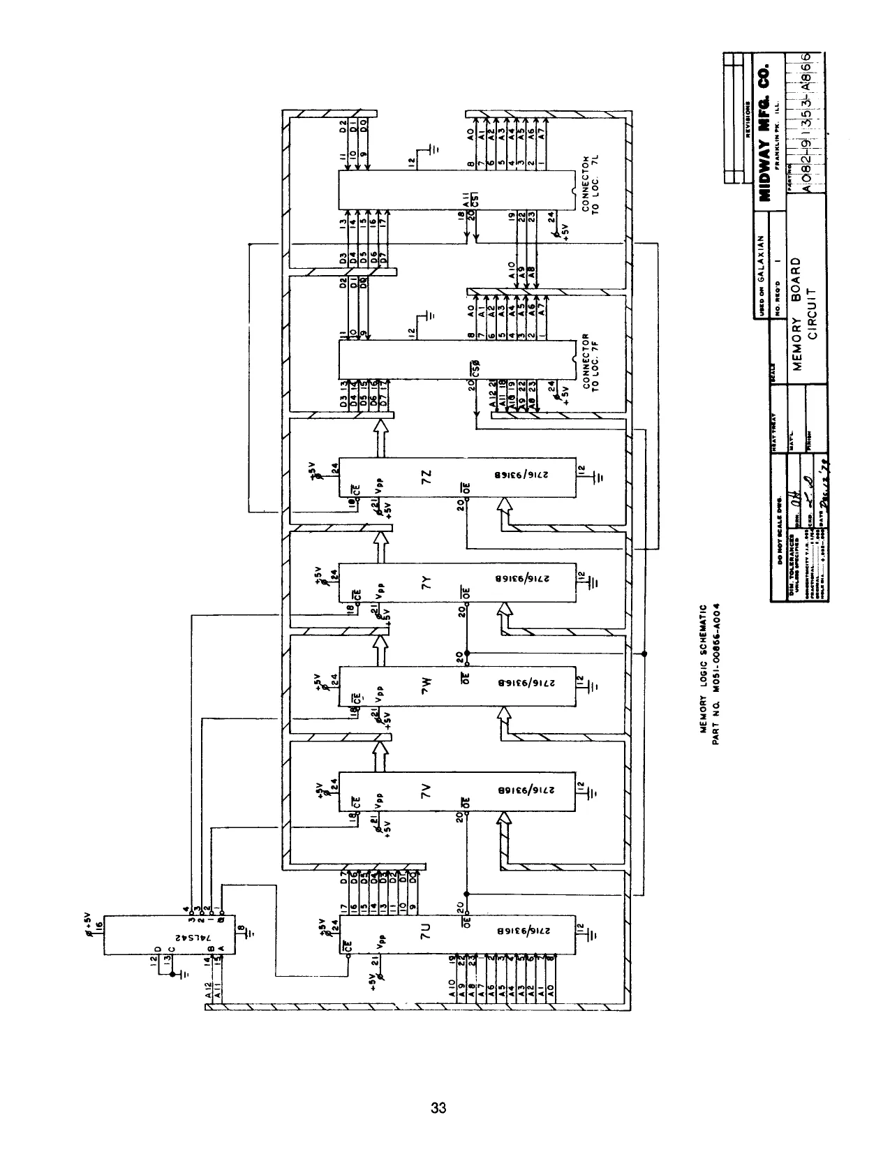
This page is a drawing, shown as the original scan.
y Twomton ene
biseuaY Fett
wr-82 FORMER oT same ual fuse H
| ' | ' | "GALAXIAN” |
| ‘ | 1 | (MIDWAY MFG. CO. |
| i | : | 10750 W. GRAND AVE. |
: : FRANKLIN PARK ILL. 6013 ' 1 a | WIRING SCHEMATIC PART NO. MoSi-00866-A003
\ i
f
} GAME LOGIC BOARD ' P.C.A0B2-91353-AB66 ara] [eww '
\ mu '
f
f orn jew ;
' '
f
f
ot j
vgawe : Hse? ‘
19 COIN DOOR & CONTROL PANEL & SONITOR CHASIS
MIDWAY MFG. CO.
‘A BALLY COMPANY
This page carries no recoverable text. It is a drawing or a photograph. See the original scan.