Smash TV Kit (16-3044-K-101) Sept 1990
Smash T.V. (rev 8.00) (Williams, 1990) · Manual · 61 pages · 70 sections · original scan
OPERATIONS MANUAL
including:
Game Operation & Adjustment
Game Testing & Problem Diagnosis Parts Information
Reference Diagrams & Schematics
WILLIAMS ELECTRONICS GAMES. INC. 3401 N. Califomia Avenue Chicago, IL 60618 16-3044-K-101 September 1990
The year is 1999
Television has adapted to the more violent nature of man.
The most popular form of television remains the game show.
One show in particular has dominated the ratings. That show is
SMASH TV. The most violent game show of all time.
Two lucky contestants compete for cash and prizes. Each contestant is armed with an assortment of powerful weapons and sent into a closed
arena.
The action takes place in front of a studio audience and is broadcast live
via satellite around the world.
Be prepared.
The future is now.
You are the next lucky contestant!
- Move with LEFT joystick to avoid enemies and gather prizes (cash and game show gifts).
- Fire weapons with RIGHT joystick and collect power-up icons for increased firepower.
- Advance to next game arena when enemies are gone.
SMASH TV KIT OPTION
This kit includes 4 joysticks, two joysticks per player. The game may also be played with 1 Rotary joystick & a fire button for each player. Many existing games have these types of controls, and may easily be kitted. However, we recommend you use the 4 standard joysticks for maximum profits. \f you would still like to use the rotary joystick control, instructions and wiring information are included for your convenience.
Table of Contents
Section 1: Kit Installation, Operation & Troubleshooting
Control Panel Modification: Typical Contro! Panel Layo! Installing PC Boards into a JAMMA Game Cabinet. Installing PC Boards into a NON-JAMMA Game Cabine' Installing the Volume Control... Game Features Starting-up.... Player Controls. Game Operation Control SWitch@S......00......ssesscsssssssescsesseeseesneeeesssssssuseesssunuesssnnneansesseeeessse 1-14 Game Adjustments and Diagnostics Starting-up.. Switch-test. DIP Switch... DIP Switch Table. CPU Board Tes! Sound Board Test. Monitor Patterns & Burn-in Tes' Coin Bookkeeping & Game Audit Game Adjustments.... 7 Pricing, Coin Counter ‘Mode, “Game Difficulty, & Lives Per Play Standard Pricing Table. Attract Mode Sound, A\ Utilities... Troubleshooting
Section 2: Parts Information
Audio Board Layout & Parts Lists. CPU Board & Layout.. CPU Board Parts List
Section 3: Diagrams & Schematics
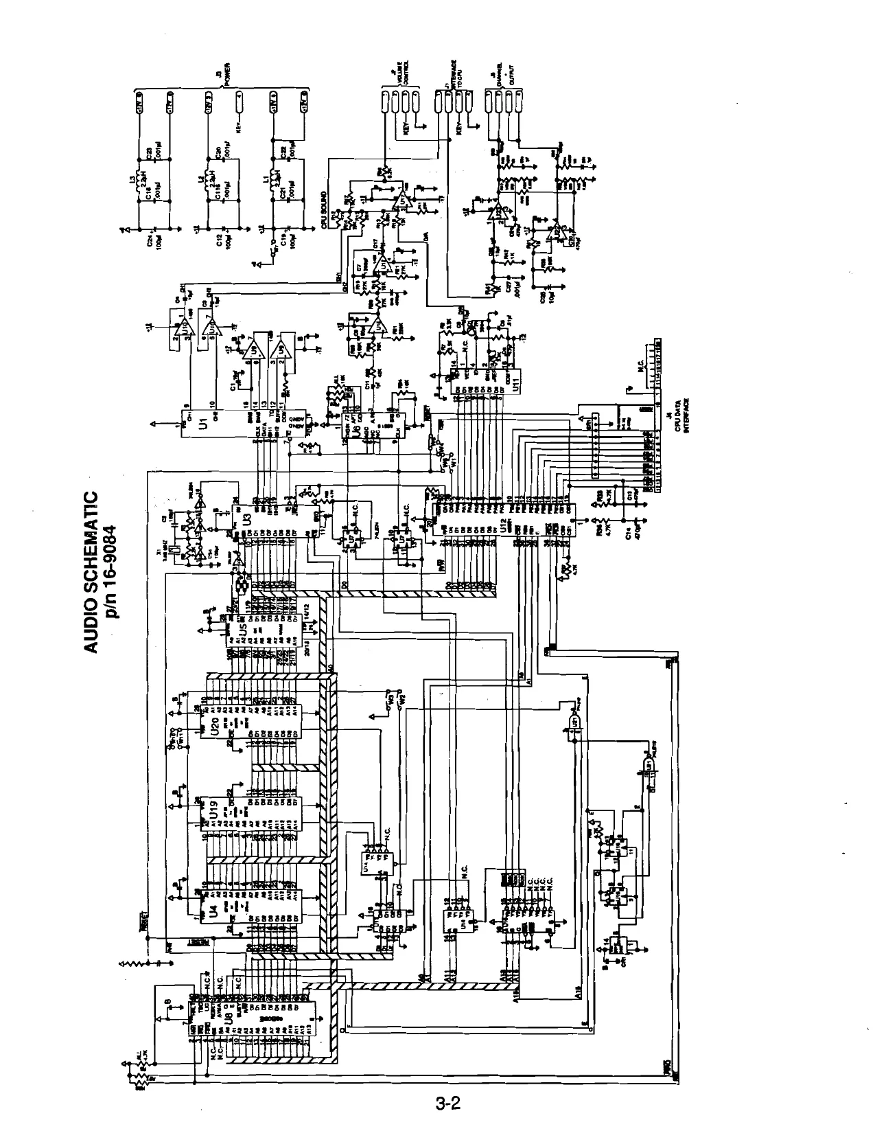
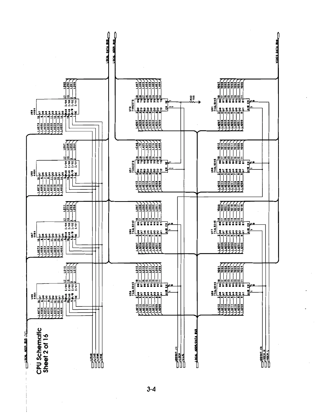
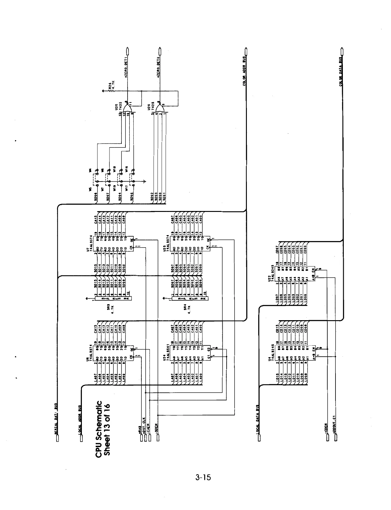
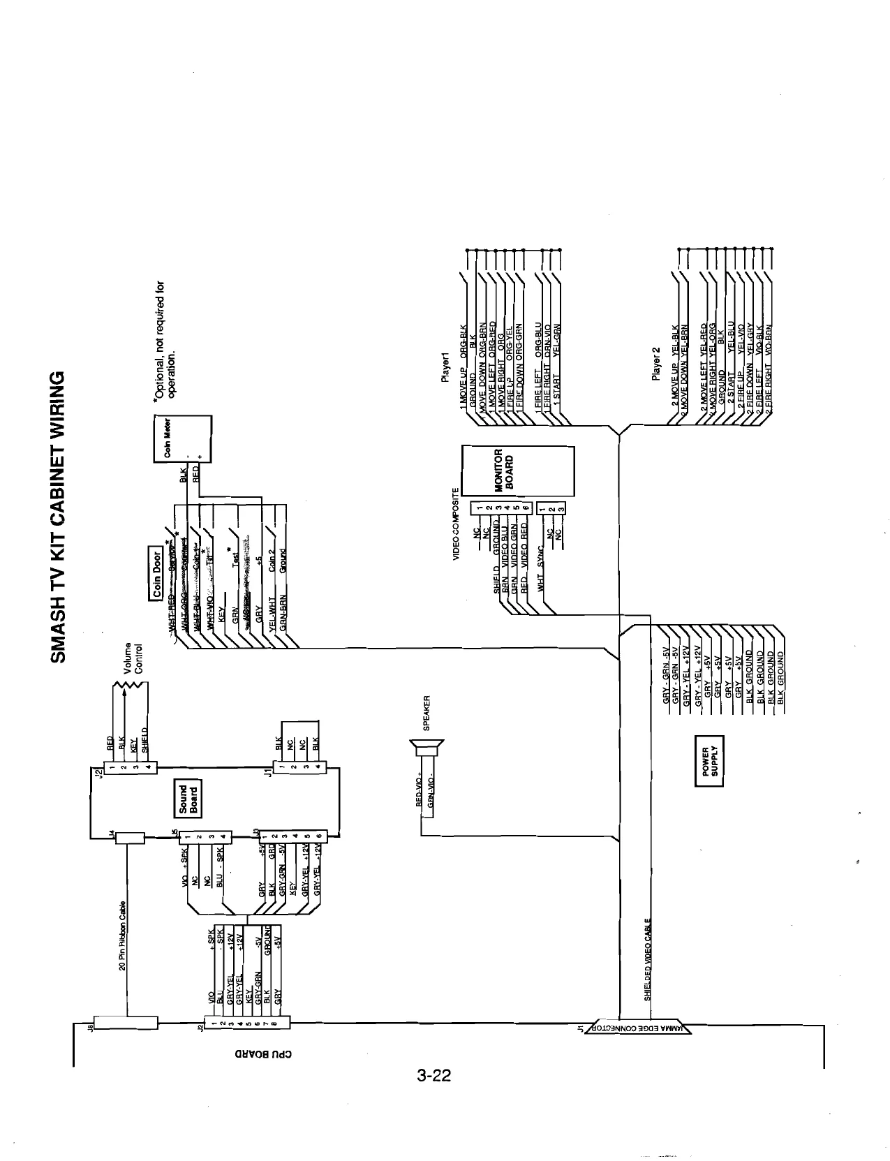
Audio Board Schematic. CPU Schematic......... Coin Switch & Meter Wiring. Interboard Wiring JAMMA Chart.. Cabinet Wiring Diagram Optional Rotary Joystick Wiring & Control Panel Information.
COPYRIGHT © 1990 WILLIAMS ELECTRONICS GAMES, INC. ALL RIGHTS RESERVED
SMASH TV
SECTION one
Operation and Troubleshooting
Safety Notices
The following safety hints apply to all kit operators and service personnel. Specific warnings and cautions will be found throughout this manual where they apply. We recommend that you read this page, and also all of Section 1, before preparing your kit for play.
NOTICE: SALVAGED PARTS Parts salvaged from old games are required to complete your kit. These salvaged parts must operate perfectly: otherwise, the converted game cannot perform properly or safely. Always repair circuit board malfunctions and cabinet damage before conversion is attempted.
NOTICE: POWER SUPPLY Be sure the power supply from your old game is capable of +5V dc at 5A ,-5V de at 1A and +12V at 1A. These operating voltages are necessary for your kit. Your power supply must be FCC approved.
NOTICE: MONITOR This kit is not intended for use with X-Y monitors. Suitable monitors have horizontally mounted CRTs and raster electronics with inputs for red, green and blue video, as well as separate horizontal and vertical Negative Sync inputs,
NOTICE: COIN MECHANISM Be sure to clean and lubricate your old coin mechanisms. Servicing them Is crucial to your game's eaming potential and operation.
NOTICE: COIN METERS Coin meters are not provided with this kit. Wiring information is provided as a convenience to the operator.
NOTICE: SERVICING, INSTALLING Always tum your game OFF and unplug it before attempting to service or install your kit.
PROPERLY ATTACH ALL CONNECTORS. Be sure that the connectors on each printed circuit board (PCB) are properly connected. If they do not slip on easily, do not force them. A reversed connector may damage your kit and void the warranty. All connectors are keyed to fit specific pins on each board.
Conversion Procedure
Inspection Unpack the materials from the carton and inspect for obvious signs of damage. Use this checklist to be sure your kit is complete.
Part No. Item Quantity
| () C-9214-5 | Button Assy Wht | 2 |
| () C-13234-3044 | CPU Assy Y-Unit | 1 |
| () D-11581-3044 | Audio Sound Brd Assy | 1 |
| () D-13604 | Sound Brd & Plate Assy | 1 |
| () H-8866 | Volume Control Cable | 1 |
| () H-12758 | Sound Board Jumper | 1 |
| () H-13257 | Sound Pwr/ Spker Cable | 1 |
| () H-13411 | JAMMA Main Hamess | 1 |
| () 03-8338-1 | 1/4 PC Spacer | 7 |
| () 16-3044-k-101 | Manual | 1 |
| () 16-8850-289 | PCB Assy Label | 1 |
| ©) 16-8587-795 | FCC Label | 1 |
| ©) 16-8587-825 | FBI Label | ] |
| () 16-8587-892-1 | Williams Kit S/N Label | 1 |
| () 16-8903 | Game Registration Card | 1 |
| () 20-9222 | 5/8 Palnut | 2 |
| () 20-9319-1 | 8 Way Joystick! | 4 |
| () 20-9457 | Button Holder with switch | 2 |
() 31-1564-3044-K ~ Screened Cnirl. Panel 1
| () 31-1565-3044-K | Marquee-Kit | 1 |
| © 31-1566-3044-K | Decal Set | 2 |
| Q 31-1596-3044-K | Screened CRT | 2 |
| () 4106-011 15-12 | SMS #6 x 3/4 PL-HWH | 6 (4 USED IN MOUNTING SOUND BOARD PLATE) |
(2 USED IN MOUNTING VOLUME CONTROL POT)
| () 4106-01115-16 | SMS #6 x 7 PL-HWH-A | 7 | (FOR MOUNTING CPU BOARD) |
| () 4308-01123-16B | BOLT 8-32x1-CB | 16 (FOR MOUNTING JOYSTICKS) | |
| () 4408-01119-00 | Nut | 16 | |
| () 5795-10937-18 | 20-pin Ribbon Cable | 1 | |
| () 5014-12363-00 | Volume Control Pot | 1 |
Recommended Tools and Supplies () black semi-gloss paint Q electric drill ( electric screwdriver Q grease pencil or marker Q hex driver () 180 grit sandpaper or electric sander © pliers () razor knife () soldering iron and solder © wire cutters () black electrical tape () quick-hardening wood putty
LI 4-broe NO aasn STOULNOD - ALVIdWAL pSL6-91 SHIOH (8) -- . . i ca ouaivia 21
wo
1-4 SHIOH-€ <P |
+ w2/T 9
Cabinet Modifications
1. Fill in gouges with a good quick-hardening wood putty. Sand cabinet and wipe it clean.
Repaint the cabinet with black semi-gloss paint (Games wood grain sides: remove the old decals and clean the glue residue from the old decal before painting). Allow paint to dry completely.
Pencila line roughly at the top of the old graphic. Lightly moisten the cabinet with soapy water. Apply the decal starting at the top and working down. After the decal is in place, use a piece of the foam packaging as a squee gee and smooth the decal down, taking care to squeeze out the air bubbles. If you miss an air bubble, pop it with arazor blade or a pin and burnish it down. Allow 12 hours for the adhesive in the decals to set. Remove masking.
Check the SMASH TV Kit for an FCC sticker and apply it over the existing sticker on the cabinet.
When Williams ships a game, it is in compliance with FCC regulations. Your sticker is proof. If the sticker is missing or damaged, legal repercussions to the owner or distributor of the game may resuit, If your game kit does not contain an FCC sticker, call Williams Electronics immediately.
Apply the Instructions (Card or Decals) to the CRT viewing glass.
Control Pane! Modifications
1, Remove the control panel buttons and joysticks and remove the old vinyl covering.
Place the template onthe control panel and use it to help you design your controi panel. You will need to use the Mounting Template twice, once forthe left side and once for the right side of the control panel. OPTIMAL CONTROL PANEL LAYOUT
One Player Two Player Credit Bution Credit Button
Move Fire Move Fire
- Drill holes as needed for the joysticks and buttons. Plug previous holes with wood blocks, putty, cardboard or epoxy. File the new holes smooth.
- Carefully remove the backing on the vinyl control panel overlay. Place the overlay on top of the control panel. Prevent air bubbles from getting under the vinyl overlay.
- a) After the overlay is on securely , use a razor knife to cut holes for the buttons and joysticks.
- Position the stickers around the appropriate button locations. Refer to the Typical Control Panel Layout diagram on the previous page for suggested button and joystick locations. (NOTE: Layout Diagram Must Be Used Twice, One For Each Player.)
- Peel the backing from the adhesive on the clear protective overlay. Position the overlay so that it covers the stickers and press it into place. Use a razor knife to cut holes for the joystick and buttons.
- To mount the pushbuttons and button-holder/switch to the control panel, push the threaded end of the pushbutton through the control panel from the top so that the threads extend through the back of the control panel. Then, take the white plastic button holder/ switch and place it over the pushbutton threads so that the threads extend through the hole in the holder. The blade switch must point toward the back of the cabinet and face you. Secure into place with a palnut. Repeat for all of the pusbutton switches.
- The joystick must be disassembled before mounting it to the control panel. Remove the 4 screws from the back of the slide assembly. Remove the slide assem bly, the PC Board, and the stop assembly. Take off the *E* ring and the white plastic spacer. Slide the knob out of the base . Mount the base to the back of the control panel. Insert the knob through the base from the front of the contro! panel. Replace the white Plastic spacer and the "E" ring. Slip the stop assembly over the knob shaft so the the legs fit into the base (do not force). Replace the PC Board component side facing you; BE SURE THAT THE CONNECTOR FACES THE RIGHT SIDE OF THE CONTROL PANEL, Install the slide as sembly so that the holes in both slides fit over the knob shaft and replace the 4 screws.
'f you choose to use your own JAMMA Cable and not the one providedin the kit, be sure to check the JAMMA Cable Connector Chart to verify that it is compatible.
Properly insulate any unused wires within the JAMMA Cable, especially the gray, gray-green and gray-yellow wires. This is a fully wired JAMMA Cable. Many of the wires will not be used for this kit, These wires have been installed so that you can use this cable for future kits,
The Ribbon Cable may need to be twisted in order to connect it properly. Installing the PC Boards and Wiring into a JAMMA Game Cabinet
- Disconnect and remove the existing video board in the JYAMMA Game Cabinet.
- Mount the SMASH TV video board inside the JAMMA Game Cabinet where the old video board was located Mount the sound board next to the video board using the stand-off and screws provided.
- If you choose to use the JAMMA Cable provided with the kit, unsolder your old JAMMA cable from the speaker, power supply, control panel switches (which may already be disconnected) and coin door. Remove the cable from the game. if you are not going to use the JAMMA Cable provided with the kit, check the JAMMA Cable Connector Chart to be sure your cable is compatibie. Leave your power supply chassis as is.
- Connect the JAMMA Cable to J1 on the SMASH TV video board. Using the JAMMA Cable Connector Chart for teference, solder the correct JAMMA Cable wires to the speaker, power supply, control panel switches and coin door.
- Connect the ribbon cable from J4 onthe sound board to J8 on the video board. Be sure that the red line goes to the same pin on both boards. Connect the wire harness cable from J5 (speaken, and J3 (bowen, on the sound board to J2 (sound power speaker connector on the video board.
- Connect the video signal cable from JP6 on the video board to your monitor. Be sure that pin 1 on the monitor is connected to pin 1 on the video board and so on.
. Connect the joystick harness from the video board to the Joystick opto boards. The player 1 connector has red wires and is connected from JP4 on the video board to the opto board on the player 1 joystick. The player 2 connector has blue wires and Is connected from JP5 on the video board to the opto board for the player 2 Joystick. The power connector has 4 wires and Is connected to JP8 on the video board.
8, JP3 on the video board is not used.
- Place the FBI Warnng Label on the inside of the cabinet next to the PC boards. Be sure the label is completely visible.
Installing the PC Boards and Wiring into a NON-JAMMA Game Cabinet.
1, Disconnect and remove the existing video board in the game cabinet.
Mount theSMASH TV video board inside the Game Cabi net where the old video board was removed. Mount the sound board next to the video board using the stand-offs and screws provided.
Leaving several inches of wire, cut the wires at the coin door, control panel switches (which may already be disconnected) speaker and power supply.
Connect JAMMA Cable to video board at J1. Follow the JAMMA Cable Connector Chart and splice the wires of the JAMMA Cable to the existing wires for the coin door, power supply, speaker and control panel. Be sure all of the spliced wires are well insulated with black electrical tape.
Connect the ribbon cable from J4 on the sound board to J8 on the video board. Be sure that the red line goes to the same pin on both boards. Connect the wire harness cable from J5 (speaker), and J3 (power) on the sound board to J2 (sound power speaker connector on the video board.
Connect the video signal cable from the JAMMA HAR NESS on the video board to your monitor.
Connect the joystick harness from the video board to the joystick opto boards... The player 1 connector has red wires and is connected from J4 on the video board to the opto board on the player 1 joystick. The player 2 connector has blue wires and is connected from J5 on the video board to the opto board on the player 2 Joystick. The power connector has 4 wires and is connected to J8 on the video board.
J3 on the video board, is not connected.
Place the FBI Warning Label on the inside of the cabinet next to the PC boards. Be sure the label is completely visible.
1-8 Be sure alll spliced wires are well insulated with black electricaltape.
Properly insulate any unused wires within the JAMMA Cable, especially the gray, gray-green and gray-yellow wires. This is a fully wired JAMMA Cable. Many of the wires will not be used for this kit. These wires have been installed so that you can use this cable for future kits.
The Ribbon Cable may need to be twisted in order to connect it properly.
1, Installing the Volume Control
Mount the volume control, using screws provided, where itis easily accessible. On top of the cash box, or on the wall near sound board are two possible locations.
The volume control cable attaches the volume controlto the sound board at connector J2. When viewed with the white plastic knob facing you. the shield wire should be soldered to the right lug, the red wire should be soldered to the middie lug, andthe black wire should be soldered to the left lug. Refer to Volume Control Diagram.
Volume Control Wiring Diagram Red Black Shield
Game Features
Starting Up
Switch on powertothe game. A “rug” patiem appears onthe crt screen. When the ‘rug" pattem ends, the screen shows CHECKING SCRATCH RAMS, and then CHECKING ROMS. The next screen shows SMASH TV REVISION LEVEL, CMOS TEST OK and the COIN SETTING. The game then moves to the attract mode. After the proper Coinage has been inserted, the game exits the attract mode and enters the play mode.
Piayer Controls
Each Credit button allows (1 or 2) players to begin play or continue play.
{Left Joysticks enable players to move through arenas.
Right Joysticks enable players to fire on enemies in arenas. SMASH TV isa one or wo player game.
SMASH TV will operate in the Test Mode, when the DIP Switch Bank #2 Switch #1 is toggled.
When an error is detected during Start-up Tests, game start-up does not progress, and an error message appears on the screen.
SMASH TV Kit will support a Test Switch (ocated on the cash box coven), if available, it can be used,
Game Operation
SMASH TV is a one or two player video game with a color monitor. From the player's perspective. the game has two modes of operation: Ready-to-Play and Play. Forthe owner/ operator, the game has an additional mode of operation called Game Diagnostics and Adjustments.
Control Switches
The COIN DOOR SLAM TILT SWITCH detects any forceful vibrations against the Coin Door. This eliminates pounding for free games. This switch is optional, the game operates without it.
{The VOLUME CONTROL cilows increasirig or decreasing the volume level of the game music and speech. For greater profits, set your game's volume level at its maximum.
The TEST/DIAGNOSTICS SWITCH allows you to enter into the game's Diagnostic mode. Move the Test Switch to the left, then back to the right to enter the Diagnostics Mode. To exit this mode, select EXITTO GAME OVER from the Diagnostics main menu. This is an optional switch. Game diagnostics can also be reached through the Dip Switch Bank 2, Switch #1,
The SERVICE CREDIT SWITCH is a special feature switch that allots credit without affecting the game's bookkeeping total. This switch is optional. the game operates without it.
Game Audits, Adjustments &
Diagnostics
Operation
AIlSMASH TV Game Audits, Adjustments, and Diagnostics are options of the Main Test Menu. Each option, in turn, has its own menu . listing several choices that you may act upon as desired.
Activate the Test Mode through the Dip Switch Table (#2) or move the Test Switch (on the cashbox lid panel) from the OFF Position to the ON position to activate the Smash TV Kit Diagnostics. Main Test Menu (shown below) then appears. Game adjustments, bookkeeping, and diagnostics are all accessible from this menu.
Move the left joystick up or down to cycle through the menu options. Notice that the options are highlighted in sequence. Selecting a desired option requires itto be highlighted. To activate the selected option, press any button.
The Main Test Menu lists six options.
SELECT WITH LEFT STICK
ACTIVATE WITH ANY BUTION
>)
f DIAGNOSTIC TESTS
COIN BOOKKEEPING
GAME AUDITS GAME ADJUSTMENT
UTILITIES
\ EXIT TO GAME OVER y
Main Test Menu
1-12
DIAGNOSTIC TESTS To enter the Diagnostic Tests from the Main Test Menu, move the left joystick to select (highlight) the Diagnostic Test option, and move the tight joystick to activate the option. The Diagnostic Tests Menu lists seven options.
“SELECT WITH LEFT STICK
ACTIVATE WITH ANY BUTTON |
SWITCHTEST
ROM BOARD TEST
__CPU BOARD TEST _ SOUND BOARD TEST _ MONITOR PATTERNS
RUN BURN-IN TEST
__ RETURN TO MAIN MENU
Diagnostic Test Menu
Switch Test The Switch Test allows the operator to test the switches on the contro! pane! and the coin door.
Select the Switch Test by using the leftjoystick to highlight the Switch Test option; then, move the right joystick to activate it. The top of the screen shows a layout of the control panel and the bottom of the screen lists the coin door switches. Pressing a switch causes the corresponding switch location on the screen to light. Release the switch and the screen returns to normal.
Select the RETURN TO MAIN MENU option to retum to the Diagnostic Test Menu.
DIP Switch Test The DIP Switch Test allows the operator to check the position of the two 8-position DIP switches on the CPU Board. The operator can also change the setting of each position of each DIP switch during this mode.
Select the DIP Switch Test by moving the left joystick to highlight the DIP Switch Test option; then, press any button to activate the test. The upper portion of the screen displays a layout of the DIPswitches and their current settings. The lower portion of the screen shows all of the possible settings for Coinage, Country, and Number of Players. OFF (0) indicates that a switch is open. ON (1) indicates that a switch is closed.
To change the setting of either DIP switch, press the switch position (SW1 - SW8) to the desired setting (ON from OFF (1 from 0), or vice versa). Check the upper portion of the screen to verify that the switch now shows the setting desired.
Press any control pane! buitonto return tothe Diagnostic Test Menu. The numbers preceding Coinage (643) (on DIP #1) and, on DIP #2, Country (21),and Number of Players (65) are the position numbers on the DIP that must be used tomake that setting.
SMASH Tv DIP SWITCH SETTINGS
DS1 (1st bank)
| COUNTRY COIN MODE SW3 SW4 SW5 SW6 SW7 SWS
| USA1 | L=1/.25 R=1/.25 | OFF OFF OFF OFF OFF OFF; |
| USA 2 | L-1/2X.25 R=1/2X.25 | OFF OFF OFF OFF OFF ON |
| USA3 | L, R=1/2X.25; 2/3X.25, 3/4X.25 | OFF OFF OFF OFF ON OFF |
| GERMANY 1 | L=1/1DM, R=6/5DM, (3)=2/2DM | OFF OFF OFF OFF ON ON |
| GERMANY 2 | L=1/1DM, R=7/5DM, (3)=2/2DM | OFF OFF OFF ON OFF OFF |
| GERMANY 3 | L=6/5DM, R=2/2DM, (3)=1/1DM | OFF OFF OFF ON OFF ON |
| FRENCH 1 | L=2/5F, R=5/10F | OFF OFF OFF ON ON OFF |
| FRENCH 2 | L=2/5F, R=4/10F | OFF OFF OFF ON ON ON |
| FRENCH 3 | L=1/3X1F, R=2/5F, (3)=5/10F | OFF OFF ON OFF OFFOFF |
| SWISS 1 | L=1/1F, R=6/5F | OFF OFF ON OFF OFF ON |
| ITALY | L, R=1/500 LIRE | OFF OFF ON OFF ON OFF |
| UK 1 | L=1/20P, R=3/50P | OFF OFF ON OFF ON ON |
| UK2 | L=2/20P, R=5/50P | OFF OFF ON ON OFF OFF |
| UK ELEC. | L=4/L1.00, R=2/50P, (3)=1/30P, (4)=1/3X10P. | OFF OFF ON ON OFF ON |
| SPAIN 1 | L=1/25 PESETA, R=5/100 PESETA | OFF OFF ON ON ON OFF |
| AUSTRALIA 1 | L=1/3X.20, R=2/1.00 | OFF OFF ON ON ON ON |
| JAPAN 1 | L, R, (3)=1/100 YEN | OFF ON OFF OFF OFF OFF |
| JAPAN 2 | L, R, (3)=2/100 YEN | OFF ON OFF OFF OFF ON |
| AUSTRIA 1 | L=1/2X5 SCHILLING, R=3/2X10 SCHILLING | OFF ON OFF OFF ON OFF |
| BELGIUM 1 | L=7/50F, R=3/20F, (3)=1/2X5F | OFF ON OFF OFF ON ON |
| BELGIUM 2. | L=3/20F, R=3/20F | OFF ON OFF ON OFF OFF |
| SWEDEN | L=1/8X1 KRONA, R=2/5 KRONA | OFF ON OFF ON OFF ON |
| NEW ZEALAND | L, R=1/3X.20 | OFF ON OFF ON ON OFF |
| NETHERLANDS | L=1/1HFL, R=3/2.5HFL | OFF ON OFF ON ON ON |
| FINLAND | L=1/2X1 MARKKA, 3/5X1 MARKKA | OFF ON ON OFF OFF OFF |
| NORWAY | L=1/2X1 KRONE, R=3/5X1 KRONE | OFF ON ON OFF OFF ON |
| DENMARK | L=1/2X1 KRONE, R=3/5X1 KRONE, 7/2X5 KRONE | OFF ON ON OFF ON OFF |
DS2 (2nd bank)
Switch 1 Toggle To Activate Kit Test Mode Switch 2 Close Switch To Enable Rotary Joystick Option
As soon as a faulty chip is detected, the CPU Test stops. The remaining chips are not tested. CPU Board Test The CPU Board Test (much like the Start-up Test) allows the operator to check the RAMs and ROMs.
Move any joystick to select the CPU Board Test; then, press any control panel button to activate the automatic test of the CPU Board's RAMs and ROMs. When this test is activated, a “rug" pattern appears on the screen. The screen then changes to show the layout of the RAMs, and ROMs on the CPU. Any chip that is shown as black with a white outline is part of the CPU and should turn either red or green during the CPU Test. Any chip that is shown as gray with a white outline is not installed in the game. During the test, chips are good, if they tum green; they are faulty, if they turn red.
Press any control panel button to retum tothe Diagnostic Test Menu.
Sound Board Test The Sound Test allows listening to some of the sounds that SMASH TV is capable of producing. This test also emits atone for each fault that is detected.
Move any joystick to select the Sound Board Test; then, press any-control panel button to activate the test.
Monitor Patterns The Monitor Patterns Test provides a menu for testing the monitor.
Move the left joystick to select a test; move the right Joystick to activate the test. (SELECT WITH LEFT STICK \ AGIA WITH RIGHT STICK )
RED SCREEN
GREEN SCREEN
|BLUESCREEN COLOR BARS CROSSHATCH PATTERNS — BACK TO DIAGNOSTICS MENU
RETURN TO MAIN MENU
\ i Z
Monitor Pattern Menu
The RED, GREEN, and BLUE SCREEN tests fill the screen with either red, green or blue. The COLOR BARS fest fills the screen with several gradiated colors to help with red, green and, blue level adjustments. Each color should appear sharp and clear. The CROSSHATCH PATTERNS test fills the screen with a grid and a series of dots. The grid and the dots should be clear. The dots should appear round.
'f any of the Monitor Pattern Tests shows a need for adjustment, use the proper white knobs on the Monitor Board.
Move right joystick to return to the Monitor Pattems Menu. From this menu, select RETURN TO MAIN MENU with left joystick and activate with right joystick.
Burn-in Test The Burn-in Test continually repeats the CPU Board Test. Move any joystick to select the Burn-in Test; then, press any button to activate the test. When the Bum-in Test detects an error, the test stops and displays an error message on the screen. The third page of the Audit Table specifies the number of Bum-in cycles successfully completed. Use this test to find intermittent CPU problems.
To exit this test, switch off the game; then, switch it on again.
1-17
COIN BOOKKEEPING To enter the Coin Bookkeeping from the Main Test Menu, move the left joystickto select the Coin Bookkeeping option; then, move the right joystick to activate it.
The Coin Bookkeeping Table records the coinbox totals and game play counters. The left side of the table names the bookkeeping Item; the right side shows the number of coins, credits, or plays for each item.
-LEFTSLOTCOINS _RIGHTSLOT COINS ___ CENTER SLOT G) COINS _ EXTRA SLOT @) COINS PAIDCREDIS TOTAL COLLECTION | pee ceece
- PLAYS UNTIL HIGH SCORE RESET “S000
_-RETURNTO MAIN MENU
Coin Bookkeeping Table
To exit Coin Bookkeeping, move the left joystick to select RETURN TO MAIN MENU; then, press any button to activate it.
GAME AUDITS To enter Game Audits from the Main Test Menu, move the left joystick to select the Game Audits option; then. press any button to activate it. To advance to the next (or return to the previous) page of the Game Audit Table, move any joystick to select either "Next Audit Page”, or "Previous Audit Page"; then, press any control panel button to change the page.
The Game Audits Table records the game play statistics. The left side of the table names the Audit item; the right side shows the amount of play. 1-18
> GAMES STARTED | (FROM ANYWHERE) oO. a) GAMESCONTINUED om MEN COLECTED EARNED HOURS OF SINGLE PLAY. co
TOTAL HOURS OF PLAY
NG. "PLAYER" GAME TIME in) o
as Bt 0 _ HOURS OF DUAL PLAY oo
‘AVG. ELAPSED TIME/PLAY LL Se | RETURN TO MAIN MENU PAGE 1 OF AUDIT TABLE GAMES: STARTED (ALWAYS FROM wave » | ‘REACHED WAVE: 2. 4 REACHED MUTOID MAN
REACHED ‘CIRCUIT. 2WAVE 1
REACHED SCAR FACE REACHED TEMPLE WAVES REACHED END OF GAME,
REACHED CIRCUIT 3 WAVE 1
REACHED BOSS SNAKES o
| LockuPs e@ cee coco eo eae
_RETURN TO MAIN MENU S f PREVIOUS AUDIT PAGE |
PAGE 2 OF AUDIT TABLE
To exit the Game Audit Table , move the left joystick to select RETURN TO MAIN MENU; then, press any button to activate it.
GAME ADJUSTMENTS Move the left joystick fo select the Game Adjustment option on the Main Test Menu; then, press any button to activate it.
The Game Adjustments option allows the owner/operator to change the Game Pricing and Game Difficulty.
The Game Adjustment Menu offers several choices. Each choice hasits own menu. Move the left joystick to select your choice to be changed from the Game Adjustments Menu: then, press any button to activate that choice. On the next menuscreen, move the leftjoystickto select the item you wish to modify; then, press any button to activate that item. If the activated Item only provides a setting choice, move the left joystick to change the current setting to the desired value; then, press any button to lock in the desired value. Moving the joystick up increases the setting value shown on the screen. Moving the joystick down causes the value shown on the screen to decrease.
\ Ree RIGHT STICK TO MODIFY >)
SELECT WITH LEFT STICK )
(canDaRO PRICING
CUSTOM PRICING
COIN COUNTER MODE @ | choices)
GAME DIFFICULTY LIVES PER PLAY
ATTRACT-| -MODE SOUND
AUTO HIGH SCORE RESET
VIDIENCE LEVEL {eetuew To MAIN MENU. Game Adjustment Menu
1-20
Standard Pricing
Standard Pricing allows the operator to choose any of the “Standard” selections for the Standard Pricing Table. Standard Pricing cannot be installed when either Custom or DIP Switch Pricing is in effect.
(NOTE )
The SMASH TV Standard Pricing Table is on page 1-19.
Press any button to return to the Game Adjustments Menu.
Custom Pricing
Custom Pricing allows the operator to install pricing other than that of the Standard Pricing Table. Custom Pricing also allows the operator to select the maximum amount of credits per game. the amount of credits required to start a game, and the amount or credits required to continue a game. Custom Pricing cannot be installed when DIP Switch Pricing is in effect.
Press any button to return to the Game Adjustments Menu,
Coin Counter Mode Coin Counter Mode allows the operator to select the appropriate counter mode. The three choices are:
- Proportional Count
- One count per coin
- Two coin Counter(s) a. right b. left
Game Difficulty
Game Difficulty allows the operator to select the difficulty level of the game. The range of this setting Is Easiest (1) to Hardest (10).
Press any buttion to return to the Game Adjustments Menu.
Lives per Play Lives perPlay allows the operatorto select the numberoflives a player receives each time a game Is started or continued.
Press any button fo return to the Game Adjustments Menu.
1-21
SMASH TV STANDARD PRICING TABLE
SETTING LEFT | CENTER| RIGHT NAME _Credit/coin cHuTe_| cHuTE | CHUTE
| USA1 | 11256 | 25¢ | 25¢ | |
| USA 2 | 1/50¢ | 25¢ | 25¢ | |
| USA3 | 1/50¢, 2/75¢, 3/61 | 25¢ | 25¢ | |
| GERMANY1 | | 1/1 DM, 6/5 DM, (3) = 2/2 DM | 10M | 2pm | 5DM | |
| GERMANY 2 | | 1/1 DM, 7/5 DM, (8) = 22 DM | 1DM | 2DM | | 5DM |
| GERMANY3 | 6/5 DM. 2/2 DM, (8) = 1/1 DM | 5DM | 1DM | 2DM | | | |
| FRENCH 1 | 2/5 F, 5/10 F | 5F | 10F | |
| FRENCH 2 | 2/5 F, 4N0F | 5F | 10F | |
| FRENCH 3 | 1/3X 1 F, 25 F, (3) = 510 F | 1F | 1F | 5F |
| Swiss 1 | 1H F, 6/5 F | 1F | 5F | |
| ITALY | 1/500 LIRE | 500 LIRE | 500 LIRE | |
| UK 1 | 1/20 P, 3/50 P | ‘| | 20P | 50P |
| UK2 | 2/20 P, 5/50 P | 20P | 50P | |
| UK ELEC. | 4/L 1.00, 2/50 P, (3) = 1/30 P, (4)=1/3X10P | L1.00 | j|30P,10P| | 50P |
‘| 100
| SPAIN 1 | 1/25 PESETA, 5/100 PESETA | 25 PESETA | en |
| AUSTRALIA 1 | 1/3X .20¢, 2/81.00 | 20¢ | $1.00 | |
| JAPAN 1 | (8) = 1/100 YEN | 100 YEN | 100 YEN |
| JAPAN 2 | (3) =2/100 YEN | 100 YEN | 400 YEN |
’ 5 10
| AUSTRIA 1 | 1/2 X 5 SCHILLING, 9/2 X 10 SCHILLING | SCHIELING | koHiLLinc | |
| BELGIUM 1 | 7/50 F, 3/20 F, (3) = 1/2X5F | 50F | 5F | 20F |
| BELGIUM2 | | 320F,3/20F | 20F | 20F | |
| SWEDEN | 1/3 X 1 KRONA, 2/5 KRONA | 1 KRONA | 5 KRONA | |
| NEW ZEALAND | 1/3 X .20¢ | 20¢ | 20¢ | ||
| NETHERLANDS | 1/1 HFL, 9/2.5 HFL | [ 1 HFL | 2.5 HEL | ||
| FINLAND | 1/2 X 1 MARKKA, 3/5 X 1 MARKKA | 1 MARKKA | 1 MARKKA | |
| NORWAY | 4/2 X 1 KRONE, 3/5 X 1 KRONE | 1 KRONE | 1 KRONE |
DENMARK 1/2 X1 KRONE, 3/5 X 1 KRONE, 7/2 X5KRONE) 1 KRONE | 5 KRONE] 1 KRONE
1-22
Attract Mode Sound Attract Mode Sounds allows the operator to determine if the game has sound during the Attract Mode.
Press any button to return to the Game Adjustments Menu.
Auto High Score Reset
Auto High Score Reset allows the operator to determine how many plays must occur before the all time high scores are automatically reset to faciory settings.
Press any button to return to the Game Adjustments Menu.
Violence Level Allows the operator to determine the Volence Level of the game.
Press any button to return to the Game Adjustments Menu.
To return to the Main Test Menu, move the left Joystick to select RETURN TO MAIN MENU; then, press any button to activate.
1-23
UTILITIES On the MainTest Menu, move the left joystick to select the Utilities option: then. press any button to activate it.
The Utilities option allows the owner/operator to clear the game's bookkeeping memory and to install a custom message. ~ SELECT WITH LEFT STICK ACTIV. \ WITH ANY BUTTON
CLEAR CREDITS — CLEAR com COUNTERS
CLEAR GAME avons:
RESET HIGH SCORES
DEFAU LT ADJUSTMENTS
FULL FACTORY RESTORE
RETURN TO. \ All MENU
Utilities Menu
Move the left joystick toselectan item fromthe Utilities Menu; then, press any button to activate that item. Afteranitem has been activated, youare giventhe option of resetting the item ornot. For example;
CLEAR CREDITS
ARE YOU SURE ?
YES
Move the left joystick to choose YES or NO; then, press any button to lock in your choice and to retum to the Utilities Menu.
To exit Utilities. move the left Joystick to select RETURNTO MAIN MENU: then, press any button to activate it.
1-24
Troubleshooting
Problem Possible Solution
NO PICTURE Check for faulty video board or OR DISTORTED monitor. Check for disconnected PICTURE. video signal cable.
TURN GAME ON & Check line fuse. Check for +5V de NOTHING HAPPENS _ at pins C, D, 3, and 4 of the JAMMA Connector.
NO SOUND Check the speaker and speaker connection to pins L and 10 on JAMMA Connector. Check volume control setting. Check for +12V de at pins F and 6 on the JAMMA Connector. Check interboard wiring from CPU Board to Sound Board,
MOVE JOYSTICK, Check for open wires between BUT PLAYER DOES Joystick and CPU Board. Check for NOT MOVE OR FIRE — contamination on joystick switch contacts and CPU Board pins. SEE NOTE
Check for proper ground.
PRESS START Check for open wires between BUTTON AND button and CPU Board. Check for NOTHING. contamination on CPU Board pins HAPPENS or button switch blade contacts. Check for proper ground.
NO CREDIT GIVEN Check DIP switch coin setting. WHEN COINS ARE Check for contamination on coin INSERTED switch contacts. Check for an open wire between Coin Switch 1 and pin 16 on JAMMA Connector or Coin Switch 2 and pin T of JAMMA Connector.
TOO MANY CREDITS Check Game Pricing setting. Check FOR NUMBER OF for a short between pins T & 16 on COINS INSERTED JAMMA Connector.
GAME STAYS INTHE — Check that the Test Switch in the coin TEST MODE. door and the Test Switch (Position 6) | on DIP Switch 2 are set to Off.
1-25
NOTES
SMASH TV
Parts Information
Audio Board Assembly p/n D-11581-3044 Pert Number Cit Designetor Description 5766-12190-00 Bare P. C. Board
| §971-11087-00 | Ut | 16, D/A Conv, YM3012 |
‘8) §700-09008-00 Socket, IC, 16-pin (U1)
| 8370-11086-00 | U3 | 16, Sound Processor, YM2151 |
¢) 5700-09004.00 Socket, IC, 24-pin (US)
| 5400-10320-00 | Us | 1G, pProcessor, MC88BO0E |
‘8) 5700-08085-00 Socket, 1C, 40-pin (U8)
| A5349-9044-3 | U4 | 6, Audio ROM 1 |
A6349-9044-4 | U19 IG, Audio ROM 2
| A-6349-9044-5 | U20 | 1G, Audio ROM 3. |
) 700-101 76-00 Socket, IC, 28-pin (U4, U19)
| 8871-00152-00 | U1 | 16, D/A Convtr, MC1408 |
| 5430-10322-00 | U12 | {C, PIA, MCssB21 |
| 5340-10139-00 | U6 | 1G, RAM/S 6516-2 2x8 |
| 5281-00487-00 | U168 | 1C, Dual D Fipfop, 741874 |
| 5281-10043-00 | U13 | 16, 748175 |
| §281-00235-00 | U21 | {C,Triple NAND, 74.810 |
§970-00321-00 UP, U10, U17, U18 IC, Op Amp, MC1458
| 8281-00216-00 | UZ | 1G, Hex Inv, 74.804 |
| 5281-00240-00 | U14 | 1G, 2-4 Deo, 7415139 |
| 5281-09745-00 | U16 | 1G, Dual Mux, 7418138 |
8370-00166-00 U22, U23 AG, Audio Amp, TDA2002 ‘8) 6705-00199-00 Heatsink, #60308
- 4008-01003-06 Mach. Sorew, 6-32 x 9/8 ¢) 4408-01117-00 (Nut, 6-32 Hex, @) 4703-00007-00 Lockwasher, #6 Ext.
| 5160-10280-00 | Q1 | ‘Transistor, 2N3904, NPN |
| 5080-10398-00 | SP1 | SIP 4.7K & 470pid, BRBC |
5010-00181-00 Ras, RAB Resistor, 1.00, 1/2W, 5%
| 6010-00181-00 | R35, RAS | Resistor, 2.20, 1/4w, 5% |
6010-09981.00 R43, F48, R47 Resistor, 2200, 1/2w, 5% 6010-00968-00 Rat, RA2 Resistor, 1K, 1/4w, 8%
| 5010-08098-00 | 2, R3, | Resistor, 2.2K, 1/4w, 5% |
| 8010-08083-00 | A7-RO | Resistor, 3.9K, 1/4w, 5% |
| 6010-08001.00 | RI, R4, RE, AI1, | Resletor, 4.7K, 1/4, 6% |
R25 - R28, R33, R36, R37, R49, R50 *17 capacttors (shown on diagram with “B" symbol) provide +5VDC fitering for ICs. All capacttors are ceramic, 50v, axlal, unless otherwise noted. ‘All resistors are 5%, 1/4w, Carbon Flim, unless otherwise noted, Notes:
2-2 Peri tumber Ckt Designator 5010-10085-00 R14, RIS 5010-00034-00 R22-R24, R17, R34 5010-09324-00 Fé, R19, R20, R21 5010-00162-00 R30 010-08331.00 R16 6010-08772.00 R18 6010-08824-00 R32 5010-08848-00 R31 6010-08991-00 R12 6010-08219-00 R38 6010-10258-00 R40 5010-00179-00 R10 6010-08333-00 R29 6010-08342-00 R30 010-09634-00 WO 15040-09343-00 C1, C3, C4, C8 B040-10974-00 C12, C19, C24 5040-09776-00 C26, C30 5040-12008-00 629, C32 6041-00243-00 C25, C28 6043-08980-00 C5, B (17)* 6043-08996-00 C31, C33 §043-00085-00 €13- C15 6043-09492-00 C2, C34 043-09844.00 C8 5043-09645-00 C18, C18, C20- 8520-00020-00 X1 8521-10991-00 CRI 6551-00822-00 L1-L3 8791-00437-00 J4 8791-10862-04 J1, J2, U5 5761-10862.06 JS 16-8850-260 20-9220 Resistor, 13K, 1/4W, 6% Resistor, 15KQ, 1/4W, 6% Resistor, 43K2, 1/4W, 6% Resistor, 220K, 1/4W, 5% Resistor, 4.7K0, 1/4W, 6% Resistor, 8.2K, 14W, 5% Resistor, 1M, 1/4w, 6% Resistor, 5.9M, 1/4w, 6% Resistor, 180K0, 1/4W, 5% Resistor, S6KA, 1/4W, 6%
Capacitor, 470ufd, 16¥; +60, 10% Capacitor, 1000ufd, 16v, 20% Capacitor, 10ukd, 10¥,£10% Capacitor, 0.01pAd, 60v,+80, -20% ‘Capacitor, 0.1p1fd, 60v, 220%
Capacitor, 47 pid, 60v, 220% C23, C27 Crystal, 9.68 MHz Orctiator, 8 MHz Inductor, ul, SA ‘Connector, 20 pin, (Har), Rib. Cbt : pin, (Her), ‘Connector, 8 pin (Hdr) P.CB.1.D. Label ‘Thermal Compound
This page reads as a drawing: its text was drawn rather than typeset, and comes out in fragments. See the original scan.
Part No.
5770-12585-00
5281-09737-00 5317-12211-00
5317-12212-00
5317-12208-00
5340-12242-00 5700-12047-00 5340-12213-00 §521-12604-00 5521-10318-00 5283-10468-00
5019-10849-00 5317-12305-00 5700-12253-00 5280-09309-00 5281-09487-00
5434-12255-00 5700-09915-00 5311-12287-00
5700-10176-00 5311-12285-00 5340-12014-00 5283-10552-00 5370-12602-00 5317-12023-00 5700-12088-00
§700-12254-00 5317-12024-00 5700-08985-00 5010--08991-00 5010-10204-00 5010-10205-00 5010-10000-00 5010-09219-00 5010-08772-00 5010-09001-00 5010-09036-00 5010-094 16-00 5010-08997-00 5010-09534-00
5043-08980-00 5040-08986-00 5043-09845-00 5041-09243-00 5043-8996-00 5019-12611-00 Y-UNIT CPU ASSEMBLY p/n C-13234-3044-K
Ckt.Designator Description
Bare PC Brd. ut IC, 74LS 86 U2, U20, U24, U43 U6t, Ué2, U70 KC, 74ALS541 U3, U6, U7, U21,U25 74ALS574 U50, U58, U63, U64 U71, U72, U74, U79, Us4, U85. U4, U22, US4-U57 TAALS245 US9, Uso, U75-U78 Uso, U81, U4, U110 U5, U23 {C, 8K x8 S RAM U8, U52, U3, USS 24 pin Socket Ut0, U11, U28-U33 IC, 4461 VRAM ute 40 MHZ Xtal ui7 24 MHZ Xtal U19, U45 IC, 74774
U27, U34, U4, U48 1000 DIP Res. ss IC, 74ALS00 36 68 pin Socket u37 Ic, 7407 38 Ic, 74/874
39 (C, MAX691 U40-U42 20 pin Socket 47, Ude, U87,U100 IC, 740541 Ut01, U103, U104 u49 28 pin Socket 51, U73, U82 IC, 74HC573 Us6-Ue9 IC, 4464 DRAM us3 IC, 74F04 UB6 Ic, ULN20648, uss IC, 74AL8138 U89-U93, U95-U98 32 pin Socket U105-U109, U111-U114 use 144 pin Socket u102z IC, 74AL8139 unis 40 pin Socket R1,R24,R27 Res. 4.7K 5% 1/4W R2,R7, R12 Res. 10.2% 1/4W R3, Ra, R13 Res. 2KQ 2% 1/4W R4,R9, R14 Res. 3.9KQ 5% 1/4W RS, R10, R15 Res. 8.2KQ 5% 1/4W Re, Rit, R16 Res. 15KA 5%1/4W R23, R25 Res. 3300 5% 1/4W R26, R29-R34 Res. 1000 5% 1/4W R35-R37, R4G-R4S Res. 4700 5% 1/4W R38-R45 Res. 2.70 5% 1/4W we, Wa, W11, Wi2 Res. 00 W14, W20, W22, W24 we27, W28, W31, W32, W35, W39, W41, W43 W4d, W46, W48, W50, W52, W54, W56, W58 W60, W62, W66, W68, Ws9, W72, W74, W76 W78, W80 B Cap. 01 pid 10V C1,C2,C5,C10 Cap *00nfd 10V 3,04 Cap. .001pfd 10V cé-Co Cap. 10yfd 10V cn Cap. Apt SR1, SR2, SRE SIP, 47002 5 Res. SR9, SR12, SR13, SR1B Part No.
5019-09362-00
5019-10143-00 5060-10396-00
5671-09019-00 5551-09822-00 5645-09025-00 5641-12551-00 5881-12315-00 '5791-10862-00 5791-12461-00 5791-10850-00 5791-09437-00 5791-12461-10
Part No. 13235-41
A-5343-3044-22 A-5343-3044-23 A-5343-3044-11 A-5343-3044-12 A-5343-3044-13. NOT USED A5343-3044-15. A-5343-3044-16 A-5343-3044-17 NOT USED. NOT USED NOT USED NOT USED NOT USED A-5343-3044-6 A-5343-3044-7 A-5343-3044-8 NOT USED A-5346-3044-1 A-5346-3044-2 A-5346-3044-3 A-5346-3044-4 A-5346-3044-5 A-5346-3044-6 A-5346-3044-7 A-5346-3044-8 5340-12558-00 5400-12220-00 5410-12239-00 5880-11056-00
2-4 Ckt.Designator
‘SR3, SR4, SRE-
SR7,SR11, SR15 SR17, SR19-SR24 SRC1-SRC3 SR5 SRC4, SRC5- SRC10, SRC14 ‘SRCI6 LED1, LED2 u Ds1, DS2 Swi BI J2
6, U7 J8
Ckt. Designator Description
SIP, 4.7K.
SIP, 4700 9 Res. SIP. 4.7KQ 470pt
LED, Red Inductor, 4.7UH DIP. Sw. 16 pin Pushbutton Sw. Battory Holder 8 pin Connector 42 pin Connector 26 pin Ribbon Connector 20 pin Ribbon Connector 10 pin Connector
Description CPU Subassembly (includes all parts except the following list)
\C, Game EPROM IC, Game EPROM IC, Game EPROM IC, Game EPROM IC, Game EPROM IC, Game EPROM IC, Game EPROM IC, Game EPROM \C, Game EPROM IC, Game EPROM IC, Game EPROM \C, Game EPROM \C, Game EPROM IC, Game EPROM IC, Game EPROM IC, Game EPROM IC; Game EPROM IC, Game EPROM IC, PLD Color RAM Control IC, PLD Address Decode 1C, PLD Video RAM Controt IC, PLD Local Control IC, PLD Video RAM Sequencer IC, PLD Image ROM Control IC, PLD Misceilaneous Control IC, PLD Autoerase Controller IC, 8K x 8 Static RAM 150ns Low Power IC, TMS34010-50 GSP IC, Custom Asic Battery, Lithium 9V
SMASH TV
SECTION
THREE
Diagrams & Schematics
3-1
This page is a drawing, shown as the original scan.
This page carries no recoverable text. It is a drawing or a photograph. See the original scan.
This page is a drawing, shown as the original scan.
This page reads as a drawing: its text was drawn rather than typeset, and comes out in fragments. See the original scan.
This page carries no recoverable text. It is a drawing or a photograph. See the original scan.
Avot wnwoud 9130s aeUS
SHOWSYS Add
3-8
CPU Schematic
Sheet 6 of 16
TI av ay cr -
RS we or OT RR TE ‘sna wadv a9vnr ¢ er cm a7 av
tne voor WooT
- rd yet 9L JO 2 OUS x SyOWEYIS Ndd ‘tne vive Woot
3-9
This page carries no recoverable text. It is a drawing or a photograph. See the original scan.
ene vivd 39MmI saws
x
" T wre or eer
+0 ” Mt var $0aT zi tor t eal + ez0t
c
ni UTS Cres Tis a 3055 ot wor ote te Mie + 9801 he 5 voor Tear : ie soar a0 ze ¥ 20T soa fea te i sat re s2 azar oh . ‘zar 4 ie 7 ‘ezt
rf t azar
= z a eae evi
Tiere ten
‘ona BSauday som 9b IO 6 190US Avewrre 2901 SHDWSYSS dD
3-11
teas T0oK, ‘Cron W008 ‘o108 1406 $500, ‘€000 “or 00" T1400
XT vA XzovA XROVA ECLIN ECLA KL¥A Kova 9L JO OL J9eUS DyoWISUdS Ndd
3-12
This page reads as a drawing: its text was drawn rather than typeset, and comes out in fragments. See the original scan.
of rw ——oor WS IO ined A 7a he te rs00 zy 7 zoo el zea ‘toa 4 +007 7 ses $1001] (Ti a a rrr aun 1 oo Fa T= | zs
ee oon ers
CETEFD Tw se iow a
Te Te 9L JO Z1 JOEUS 7 | _—- = S00" a 1067
coed E
PECCeGGEES
Er Srecereny
This page is a drawing, shown as the original scan.
3-16
CPU Schematic
Sheet 14 of 16 SV. SYNC, Sacsme COLOR DATA BUS w T4aLssas Ret useo) a
CPU Schematic
Sheet 15 of 16 SS REESE a7 4.7K ASIF AES 3n | id Ee vied . T4eHCS41 2 coo rr Coon ,
coro . 003 ty 7 h C-—————] D [aI 1 tee q
This page carries no recoverable text. It is a drawing or a photograph. See the original scan.
COIN SWITCH AND METER WIRING
®@ Option 1
Coin Sw 1 +5V
' Meter JAMMA Pin 16
JAMMA Pins
@ Option 2
Coin Sw 1
JAMMA Pin 16
Coin Sw 2 > ‘ JAMMA Pin T JAMMA
Pins
Wrong Way !
GoinSwi__y JAMMA Pin T
Coin Sw2 I. JAMMA Pin 16
Gnd
Do NOT connect the coin switches this way. This Circuit is INCORRECT and will cause twice as many credits per coin.
3-19
MdO UO Zr OL, cb Lzer eg | i ayvog GNNOS
a. [2 gs te er vez veel rT aa BERR gab E jedunp eg Jonvog ewin}oA OL
Peer On 2571108 a PesniON sr a gr esr ver
pilog punos Uo rr Wald GuVOd Ndd LINN-A 5 Es
"EE a vir siosrezt lt ry Pan oN BREREP LuvHo WANE
99s Jo}euUOD eBpz YW? Bh £5 \g_2 231] er pieog Sf preg ONIYIM GYyvOdHALNI LIM AL HSVNS
3-20
SMASH TV
Jamma Chart
Function Wire Color Pin Pin Wire Color Function
Ss oo
- Optional functions, Game will funtion without these.
3-21
This page is a drawing, shown as the original scan.
Optional
Rotary Joystick Wiring Diagram
JAMMA PIN NUMBER
Switch GND « —_ PUSH 1
| + | oO | 22 |
To Rotary Switch FIRE BUTTON Player 1 Player 1
| lay | PUSH2 | 93 |
. PUSHS 54 SPARE 95
| HEADER 13, | re | oO | ee |
MOVE UP
| + | oO | ° | ps | 19 |
Joystick __. MOVE DOWN Player 1 _
| y | ¢ | Oo | ° | LEFT | 20 |
MOVE LEFT
| it | = | RIGHT | 9, |
MOVE RIGHT
- PUSHi To Roary Switch FIRE BUTTON yer cl ____PUSH2 a
PUSH3 4 SPARE
HEADER 13 vr
| ¢ | Oo | o | v |
MOVE UP
| + | oO | ° | a | A |
Joystick MOVE DOWN
Player 2 LEFT x
| + | Oo | ° |
MOVE LEFT —_ RIGHT oO oO MOVE RIGHT “Note: To make software work, Dip Switch Bank #2, Switch #2 must be in the CLOSED position.
Please find below, a suggested example of a Rotary joystick control panel layout.
© Fire
Joystick © Joystick
3-23
NOTES
Smash TV Inserted Jumpers
AUDIO BOARD P/N D-11581-3044
CPU.BOARD P/N C-13234-3044-K
+2 DIA. THRU
! 16 3:HOLES
iz DIA. THRU
- Hoves 16-9154
TEMPLATE-CONTROLS
USED ON 3044-K KIT
WARNINGS & NOTICES
- For safety and reliability, substitute parts and modifications are not recommended.
- Substitute parts or modifications may void FCC type acceptance.
- This game is protected by Federal copyright, trademark and patent laws. Unauthorized modifications may be illegal under Federal law. This also applies to Williams’ logos, designs, publications and assemblies. Moreover, facsimiles of Williams’ equipment (or any feature thereof) may be illegal under federal law, regardless of whether or not such facsimiles are manufactured with Williams’ components.
Notice When Williams ships a game, it is in compliance with FCC regulations. Your sticker is proof. If the sticker is missing or damaged, legal repercussions to the owner or distributor of the game may result. If your
game kit does not contain an FCC Sticker, call Williams Electronics
immediately.
Notice No part of this publication may be reproduced by any mechanical , photographic, or electronic process, or in the form of a phonographic recording, nor may be transmitted, or otherwise copied for public or private use, without permission from the publisher.
WILLIAMS ELECTRONICS GAMES, INC. 3401 NORTH CALIFORNIA AVENUE CHICAGO, ILLINOIS 60618